

Exar SP338, XR34350IL, SP339, SP339EER1-L, SP338EER1-L User Manual
...
REV. 2.0.1 SP338/SP339/XR34350 EVALUATION BOARD USER’S MANUAL
Evaluation Board User’s Manual
SP338/SP339/XR34350EVB
1

XR21B1411
SP338
SP339
XR34350
SW3 SW4
USB
Connector
DB9
Connector
SP338/SP339/XR34350 EVALUATION BOARD USER’S MANUAL REV. 2.0.1
1.0 INTRODUCTION
This user’s manual is for the SP338/SP339/XR34350 evaluation board. The SP338, SP339 and XR34350 are
pin compatible devices and are all offered in the 40-pin QFN package. The primary difference is that the SP339
and XR34350 only have 4 modes of operation (2 mode control pins) while the SP338 has 8 modes of operation
(3 mode control pins). Table 1 shows the different devices and packages that this evaluation board supports,
and the corresponding ordering part numbers for each.
ABLE 1: PACKAGE LIST
T
DEVICE
RDERING PART NUMBER
O
XR34350IL XR34350ILEVB 40-pin QFN U3
SP338EER1-L SP338EER1-0A-EB 40-pin QFN U3
SP339EER1-L SP339EER1-0A-EB 40-pin QFN U3
EVALUATION BOARD
ORDERING PART NUMBER
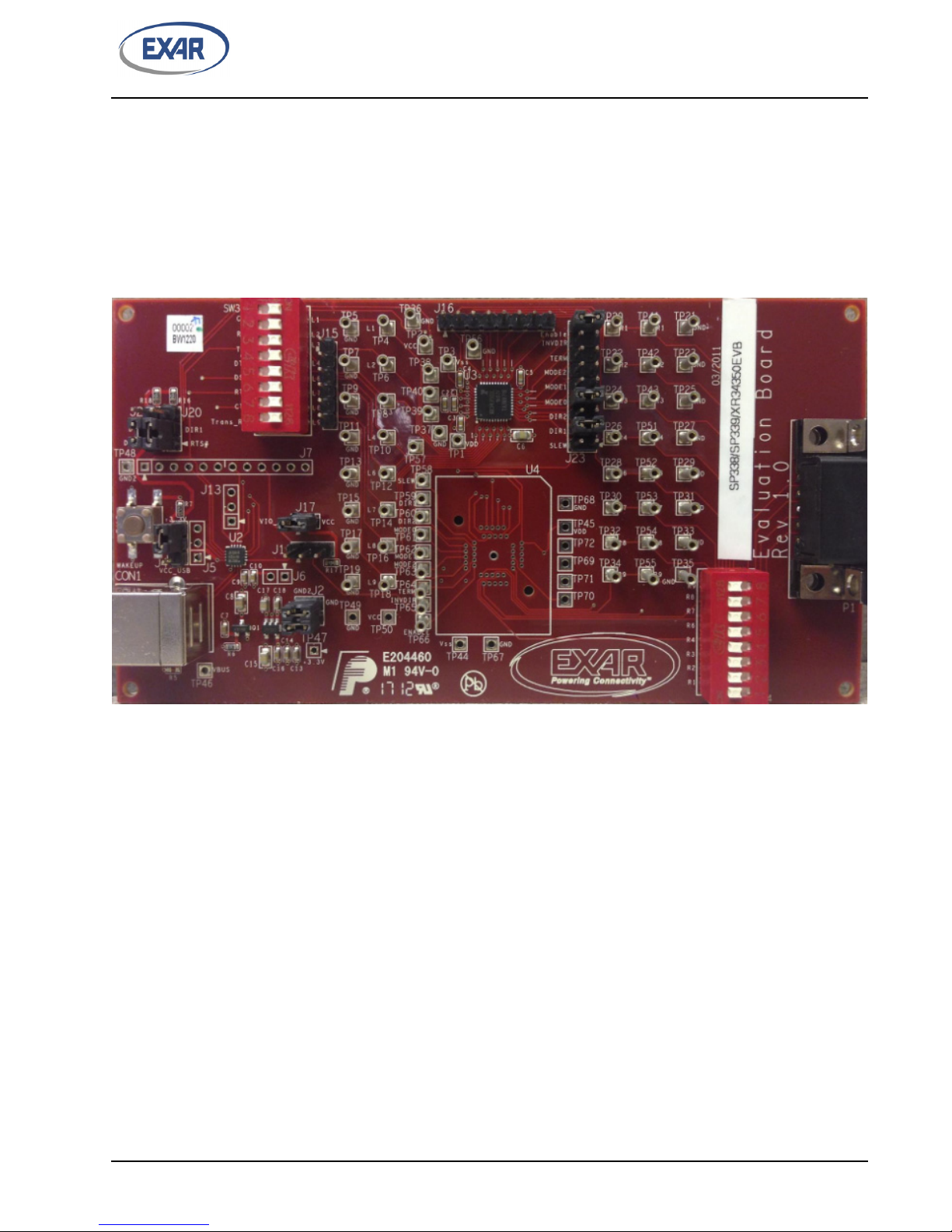
2.0 EVALUATION BOARD OVERVIEW
A block diagram of the evaluation board is shown in
F
IGURE 1. EVALUATION BOARD BLOCK DIAGRAM
PACKAGE
Figure 1 below..
DEVICE
DEVICE
LOCATION
In addition to the DUT (SP338/SP339/XR34350), there is an Exar XR21B1411 1-ch USB UART on this
evaluation board. When shipped from the factory, the SW3 and SW4 switches are off. Therefore, the SP338/
339/XR34350 is isolated from both the XR21B1411 and the DB9 connector. To enable the connections
between the XR21B1411 and the SP338/339/XR34350, place all switches on SW3 in the ON position. To
enable the connections between the SP338/339/XR34350 and the DB9 connector, place all switches on SW4
to the ON position. All SP338/339/XR34350 signals are accessible from the test points on the board. The test
points are shown in each figure showing the modes.
2.1 Mode Selection
The modes of the SP338 are selected
? Pins 7 & 8 - labeled MODE0 on the board
? Pins 9 & 10 - labeled MODE1 on the board
? Pins 11 & 12 - labeled MODE2 on the board
Note that the SP339 does not have a MODE2 pin, so the SP3
MODE0 pins.
using the following pins at J23:
39 modes are only controlled via the MODE1 and
2
TP4
TP6
TP8
TP10
TP12
TP14
TP16
TP18
Mode0 = 0
Mode1 = 0
Mode2 = 0
Enable = 1
Vcc
L1
L2
L3
L4
L6
L7
L8
L9
Vcc
11 12 13 14 15 16 17 18 19 20
40 39 38 37 36 35 34 33 32 31
1
2
3
4
5
6
7
8
9
10
30
29
28
27
26
25
24
23
22
21
All pull-downs 330kO
V+
C2+
Vcc
C1+
C1-
C2-
V-
Vcc
C3
0.1µF
C2
0.1µF
C1
0.1µF
C4
0.1µF
Cc
1.0µF
R3
R4
T3
R5
T2
T1
R2
R1
REV. 2.0.1 SP338/SP339/XR34350 EVALUATION BOARD USER’S MANUAL
The SP338/339/XR34350 have internal pull-down resistors on these pins. So the corresponding MODE pins
will be ’0’ unless a jumper is installed on the J23 pins listed above to change the MODE bit to ’1’.
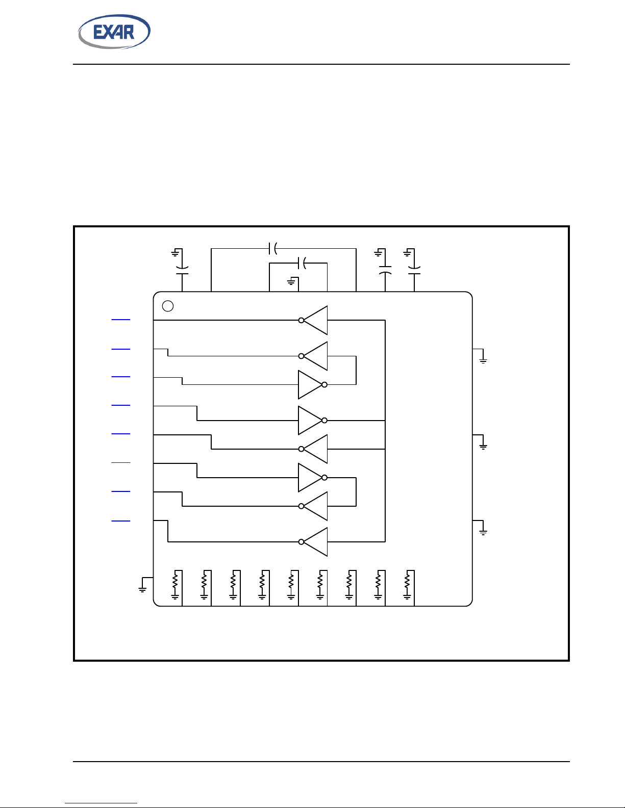
2.1.1 Loopback Mode
Figure 2 below shows the SP338/339/XR34350 configured in the Loopback mode.
? J23 Pins 7 & 8 (MODE0) - ’0’
? J23 Pins 9 & 10 (MODE1) - ’0’
? J23 Pins 11 & 12 (MODE2) - ’0’
This mode can be used for diagnostic purposes.
F
IGURE 2. LOOPBACK MODE
3
L1
L2
L3
L4
L6
L7
L8
L9
Vcc
R2
R3
R4
R6
R7
R8
R9
11 12 13 14 15 16 17 18 19 20
40 39 38 37 36 35 34 33 32 31
1
2
3
4
5
6
7
8
9
10
30
29
28
27
26
25
24
23
22
21
All pull-downs 330kO
R1
V+
C2+
Vcc
C1+
C1-
C2-
V-
Vcc
C3
0.1µF
C2
0.1µF
C1
0.1µF
C4
0.1µF
Cc
1.0µF
R3
R4
T3
R5
T2
T1
R2
R1
5kO
5kO
5kO
5kO
5kO
TP4
TP6
TP8
TP10
TP12
TP14
TP16
TP18
TP34, TP55
TP32, TP54
TP30, TP53
TP28, TP52
TP26, TP51
TP24, TP43
TP22, TP42
TP20, TP41
Slew
Mode0 = 1
Mode1 = 0
Mode2 = 0
Enable = 1
Vcc
11 12 13 14 15 16 17 18 19 20
SP338/SP339/XR34350 EVALUATION BOARD USER’S MANUAL REV. 2.0.1
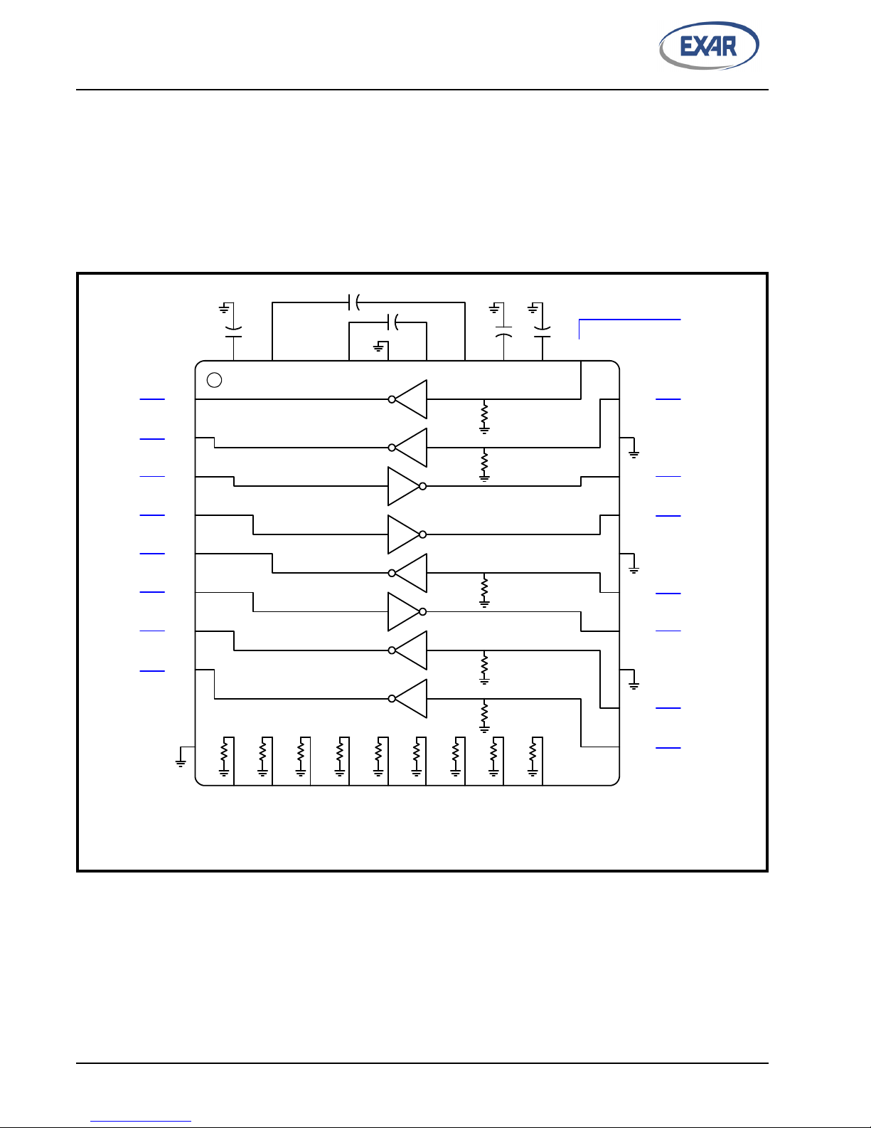
2.1.2 RS-232 Mode
Figure 3 below shows the SP338/339/XR34350 configured in the RS-232 mode.
? J23 Pins 7 & 8 (MODE0) - ’1’ (jumper installed between these pins)
? J23 Pins 9 & 10 (MODE1) - ’0’
? J23 Pins 11 & 12 (MODE2) - ’0’
This is the default setting on the evaluation
F
IGURE 3. RS-232 MODE
board when shipped from the factory.
4
 Loading...