

EXAR SP481R, SP485R Service Manual
®
1/10th Unit Load RS-485 Transceiver
FEATURES
■ Allows Over 400 Transceivers On A
Transmission Line (1/10th Unit Load)
■ High Impedance on Receiver Inputs
(RIN = 150kΩ typical)
■ Half-Duplex Configuration Consistent
With Industry Standard Pinout
■ –7V to +12V Common Mode Input
Voltage Range
■ Includes Shutdown Mode (I
(For SP481R Only)
■ Low Power Consumption (250mW)
■ Separate Driver and Receiver Enable
< 10µA)
CC
SP481R/SP485R
Now Available in Lead Free Packaging
DESCRIPTION
The SP481R and SP485R are pin-to-pin equivalent with our existing SP485 product and contain
enhancements such as higher ESD tolerance and high receiver input impedance. The higher
receiver input impedance allows for connecting over 400 transceivers on a single transmission
line without degrading the RS-485 driver signal. Each device is packaged in an 8-pin plastic DIP
or 8-pin narrow SOIC package. The SP481R offers a shutdown feature via the enable pins which
will reduce the supply current (ICC) below 0.5µA typical.
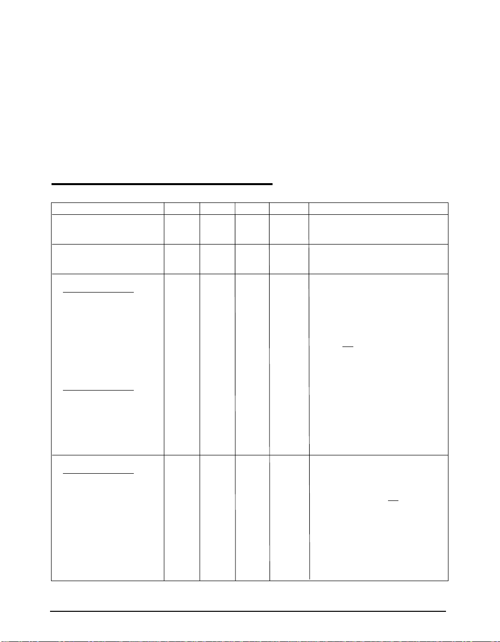
TYPICAL APPLICATION CIRCUIT
RO 1
RE 2
DE 3
R
8 V
7 B
6 A
CC
D
DI 4
SP485
Top View
5 GND
Date: 6/21/04 SP485R RS-485 Serial Transceiver © Copyright 2004 Sipex Corporation
1
ABSOLUTE MAXIMUM RATINGS
These are stress ratings only and functional operation
of the device at these ratings or any other above those
indicated in the operation sections of the specifications
below is not implied. Exposure to absolute maximum
rating conditions for extended periods of time may
affect reliability.
...........................................................................+7V
V
CC
Storage Temperature..........................-65˚C to +150˚C
Power Dissipation
8-pin Plastic DIP...........................1000mW
8-pin Plastic N-SOIC.......................1000mW
Package Derating:
8-pin Plastic DIP
ø
....................................................62 °C/W
8-pin Plastic N-SOIC
JA
øJA....................................................62 °C/W
ELECTRICAL CHARACTERISTICS
Typically 25°C @ Vcc = +5V unless otherwise noted.
MIN. TYP. MAX. UNITS CONDITIONS
LOGIC INPUTS
V
IL
V
IH
2.0 Volts
LOGIC OUTPUTS
V
OL
V
OH
2.4 Volts I
RS-485 DRIVER
DC Characteristics
TTL Input Levels
V
IL
V
IH
Outputs
2.0 Volts
Open Circuit Voltage 6.0 Volts
Differential Output 1.5 5.0 Volts RL=54Ω, CL=50pF
Balance ±0.2 Volts |VT| - |VT|
Common-Mode Output 3.0 Volts
Output Current 28.0 mA RL=54Ω
Short Circuit Current ±250 mA Terminated in –7V to +12V
AC Characteristics
Maximum Data Rate 5 Mbps RL=54Ω
Output Transition Time 30 ns Rise/fall time, 10%–90%
Propagation Delay See Figures 3 and 5
t
PHL
t
PLH
Driver Output Skew 5 15 ns see Figure 3 and 5,
60 100 ns R
60 100 ns R
RS-485 RECEIVER
DC Characteristics
TTL Output Levels
V
OL
V
OH
Tri-State Output Current ±1 µA 0.4V≤V
2.4 Volts
Inputs
Common Mode Range –7.0 +12.0 Volts
Receiver Sensitivity ±0.2 Volts –7V ≤ V
Input Impedance 120 150 kΩ –7V ≤ V
0.8 Volts
0.4 Volts I
0.8 Volts
0.4 Volts
= -3.2mA
OUT
= 1.0mA
OUT
=54Ω, CL1=CL2=100pF
DIFF
=54Ω, CL1=CL2=100pF
DIFF
t
SKEW
= | t
- t
DPLH
≤2.4V; RE = V
OUT
≤ +12V
CM
≤ +12V
CM
DPHL
|
CC
Date: 6/21/04 SP485R RS-485 Serial Transceiver © Copyright 2004 Sipex Corporation
2
ELECTRICAL CHARACTERISTICS
Typically 25°C @ Vcc = +5V unless otherwise noted.
MIN. TYP. MAX. UNITS CONDITIONS
AC Characteristics
Maximum Data Rate 1 Mbps
Propagation Delay See Figures 3 and 7
t
PHL
t
PLH
Differential Receiver Skew 60 ns | t
SHUTDOWN TIMING (SP481R)
Time to Shutdown 50 600 ns RE = VCC, DE = 0V
RS-485 Driver
Enable Time See Figures 4 and 6
Enable to Low 40 500 ns CL=15pF, S1 Closed
Enable to High 40 500 ns CL=15pF, S2 Closed
Disable Time See Figures 4 and 6
Disable From Low 40 500 ns CL=15pF, S1 Closed
Disable From High 40 500 ns CL=15pF, S2 Closed
RS-485 Receiver
Enable Time See Figures 2 and 8
Enable to Low 40 500 ns CL=15pF, S1 Closed
Enable to High 40 500 ns CL=15pF, S2 Closed
Disable Time See Figures 2 and 8
Disable From Low 40 500 ns CL=15pF, S1 Closed
Disable From High 40 500 ns CL=15pF, S2 Closed
POWER REQUIREMENTS
Supply Voltage V
Supply Current I
No Load 300 500 µA RE = VCC or 0V, DE = 0V
CC
CC
+4.75 +5.25 Volts
No Load 500 900 µA RE = VCC or 0V, DE = V
Supply Current in Shutdown 0.5 10 µA RE = VCC, DE = OV
1200 ns R
1200 ns R
=54Ω, CL1=CL2=100pF
DIFF
=54Ω, CL1=CL2=100pF
DIFF
– t
PHL
|; R
PLH
CL1=CL2=100pF, see Figures 3 and 7
DIFF
=54Ω,
CC
ENVIRONMENTAL
Operating Temperature
Commercial (..C..) 0 +70 °C
Industrial (..E..) –40 +85 °C
Storage Temperature –65 +150 °C
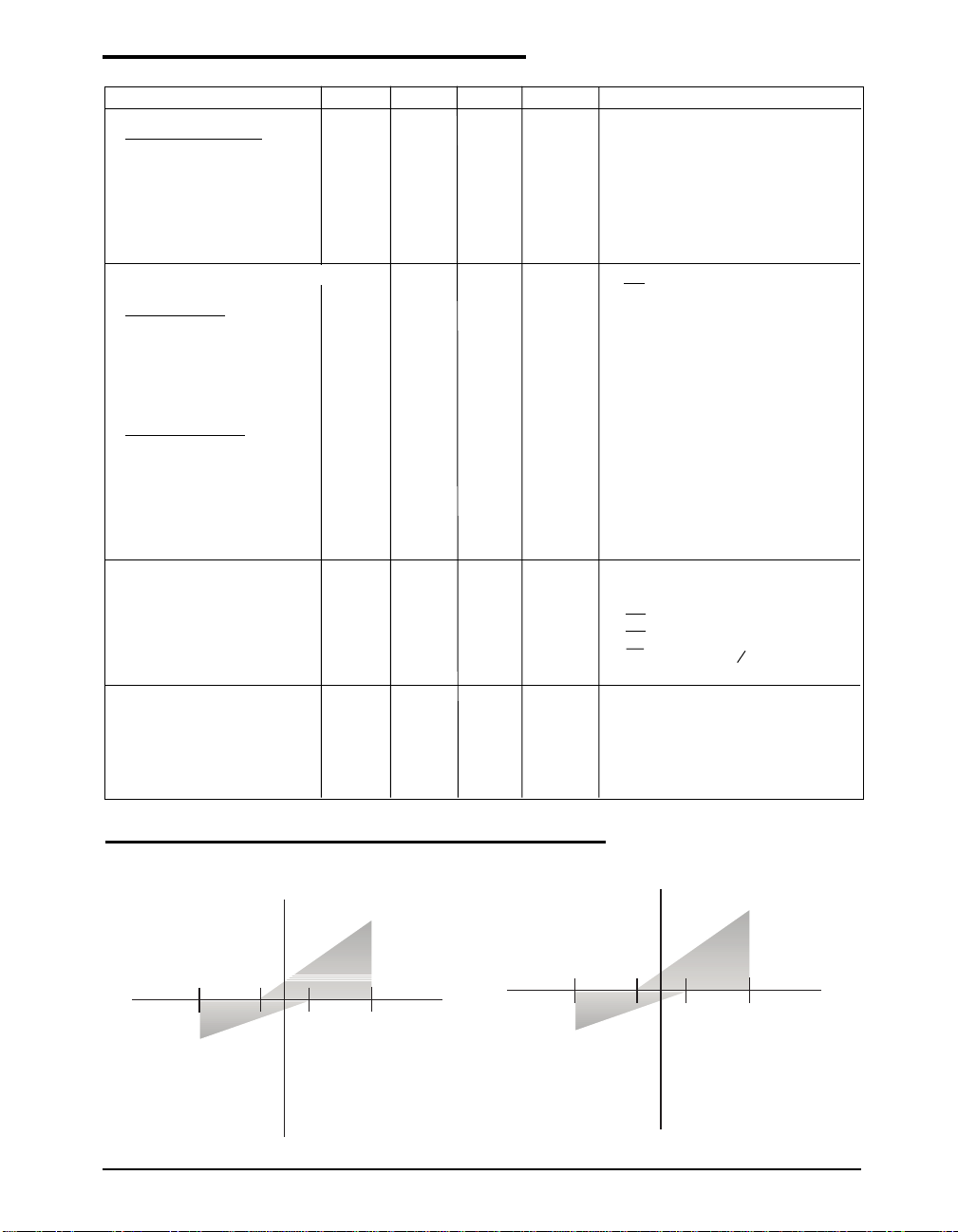
RECEIVER INPUT GRAPH
-7V
-60µA
SP485R Reciever
-3V
+6V
1/10 Unit Load
Maximum Input Current
versus voltage.
(Shaded region)
+100µA
+12V
Standard SP485R Reciever
+1.0mA
-7V
-0.6 mA
Date: 6/21/04 SP485R RS-485 Serial Transceiver © Copyright 2004 Sipex Corporation
-3V
+6V
1 Unit Load
Maximum Input Current
versus voltage.
(Shaded region)
+12V
3
 Loading...