

Exakt SP-180 Original Instructions Manual

EXAKT SP-180
1 – 5 Original Instructions
6 – 10 Übersetzte Anweisungen
10 – 15 Des Instructions Traduites
EXAKT Precision Tools Ltd.
Midmill Business Park
Tumulus Way
Kintore, AB51 0TG
United Kingdom
Designation: SP is an Exakt Sander
Planer
Tel: + 44 (0) 1467 633 800
0800 180 7063 (D)
0800 916 696 (F)
800 930 019 (I)
Fax: + 44 (0) 1467 633 900
E-mail: info@exaktpt.com
Web: www.exakt.eu
Patents Apply
Registered Design
® Registered Trade Mark
Made in PRC
94-0309_03

1 Precision Tools Ltd. 2010
English
WARNING! Never use the power tool for any purpose
other than that shown in the instruction manual.
WARNING! Keep well clear of all moving parts once
plugged in!
Safety Warnings – Instructions for
Putting Into Use
Setting up the Planer / Sander for Use
After unpacking check that there are no parts missing or
damaged. If there are, contact supplier and do not operate.
Information on Power Supply
This equipment should be connected to a normal domestic
socket outlet with a voltage rating between 210 and 250 V and
a current rating of between 13 and 16A.
Illustrated Description of Functions
1. Indicator pointer
17. Rear base plate
2. Planer depth scale
18. Front base plate
3. Depth knob
19. Fence guide
4. Sander depth scale
20. Sanding drum
5. Dust extraction duct
21. End cap removal key
6. Vacuum adapter
22. Sanding drum assembly
7. Variable hose coupling
23. Drum locking nut
8. Main handle
24. Planer drum assembly
9. Power flex
25. Planing blade cartridge
10. Start switch
26. Blade setting gauge
11. Main body
27. Drum removal tool
12. End cap screw (1 of 2)
13. End cap
14. End cap screw (2 of 2)
15. Fence guide hole
16. Fence guide clamp
28. Worktop stand
29. Shaft lock spanner
30. Locking nut spanner
31. Blade setting Allen key
32. Sanding tube
2 Precision Tools Ltd. 2010
Safety Warnings – Operating
Instructions
The Planer / Sander is designed to be used either as a
conventional hand held powered planer, or as a hand held
powered drum sander. These instructions give details on how
to set the tool for both functions.
As with all power tools this tool is powered by electricity, has
exposed rotating parts, makes noise and creates dust. To
ensure personal safety and the safety of others it is essential
that the user reads and fully understands these instructions
and then considers and assesses the dangers carefully before
use. If the user does not fully understand how to use the tool,
or does not feel confident, they should seek instruction from a
suitably trained professional before use.
WARNING ! Wait for the cutter to stop before setting
the tool down. An exposed cuttermay engage the surface
leading to possible loss of control and serious injury. Use the
workstand provided.
Setting the Sanding Cutting Depth
The sanding depth can be set to anywhere up to a maximum
indicated setting (approx. 0.5mm). When using the tool as a
sander it is not recommended to set the depth greater than the
maximum indication on the top of the sander depth scale. For
a high quality finish using less effort, make several shallow
passes. Use a lower cutting depth when working with harder
materials.
a) Identify the sanding depth scale (See Illustrated
Description of Functions)
b) Turn the depth adjuster knob fully anticlockwise until
the arrow lines up with indicator pointer
c) Turn the knob clockwise until the required depth is
achieved
WARNING! In sanding mode the drum will always
remain slightly proud of the base plate even when the arrow
indicates a minimum setting.
Changing Sanding tubes
Sanding tubes are supplied (depending on kit) with varying
grit finishes. These can be changed depending on the
amount of sanding to be carried out & level of surface finish
required. Tubes can be changed by following the
procedure.
a) Unplug the tool from the electricity supply.
b) Remove the end cap screws using the Torx key
provided
c) Pull end cap away from side of machine to expose
the tube
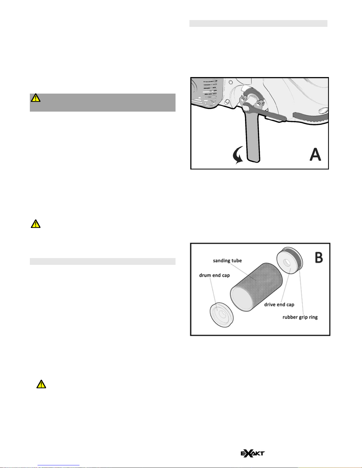
d) Using the small spanner to hold the shaft, place the C
spanner into the slots and release (Diagram A)
e) Remove the locking nut and tube assembly
f) Remove the drum end cap which should come away
from the assembly without resistance
g) Remove the drive end cap by pushing it through the
middle of the sanding tube. This part is held in-situ by
a rubber grip ring (Diagram B)
h) Replace with another tube and re-assemble
List of contents
1 x Planing / Sander
1 x Fence guide
2 x Keys
1 x Vacuum adapter
1 x Removal tool
1 x Dust bag
Spare sanding tubes
(dependant on kit)
1 x Blade setting gauge
1 x Ear plugs
1 x Instruction manual
1 x Case
2 x Spanners
1 x Dust mask
3 Precision Tools Ltd. 2010
Changing Functions
To change functions from sanding to planing follow the
instructions below. The procedure is reversed to change from
sanding to planing.
a) Follow steps a) to f) of the previous section to remove
the sanding assembly
WARNING! Do not touch exposed blades on planing
drum!
b) Using the handling tool provided, remove the planing
drum from its holder in the case
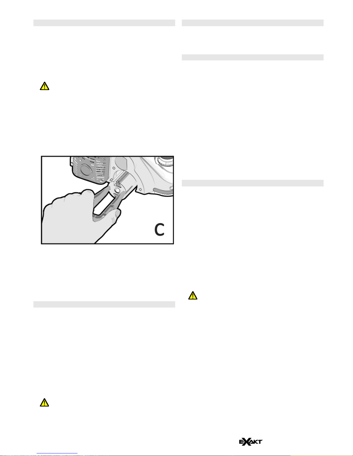
c) Replace the sanding assembly with the planing drum
assembly ensuring that it is introduced onto the shaft
drive slot first and that it is properly seated onto the
drive shaft (Diagram C)
d) Replace the drum locking nut and tighten using the
spanner provided
e) Replace the end cap ensuring it is properly seated
and flush with the side casting. Tighten the Torx
screws using the key provided
Setting the Planing Cutting Depth
The planing depth can be set to anywhere up to a maximum of
2.0mm. For a high quality finish using less effort, make several
shallow passes. Use a lower cutting depth when working with
harder materials.
a) Identify the planing depth scale (See Illustrated
Description of Functions)
b) Turn the depth adjuster knob fully anticlockwise until
the start of the scale lines up with indicator pointer
c) Turn the knob clockwise until the required depth is
achieved
WARNING! Ensure that the planing drum blades have
been set up in accordance with the instructions issued
below before using the product.
Clamping
Ensure work piece is properly supported and cannot move.
Use clamps if required.
Dust Extraction
N.B. For health reasons always use with suitable dust
extraction. The dust bag is only recommended for light use,
and should not be allowed to overfill. A suitable dust extractor
or vacuum should be attached for heavy use.
Always take appropriate precautions to avoid breathing in
dust. A dust bag is provided to avoid excess mess, but may
not provide sufficient filtration to prevent breathing in fine dust.
A dust extractor or vacuum cleaner can be used instead of the
dust bag for improved dust extraction. A suitable dust mask
(such as the one provided) should always be worn in addition,
especially if sanding harmful materials such as MDF or Glass
fibre. Never plane or sand toxic materials such as
asbestos. If in doubt consult the manufacturer of the material
before sanding or planing.
Instructions for Use
a) Wear appropriate Personal Protective Equipment
(PPE) and ensure you are not wearing any loose
items of clothing or jewellery
b) Hold the tool securely with one hand on the main
handle and the other on the depth knob
c) Always hold the tool a minimum of 15 cm from your
body and plane or sand away from your body
d) Use the worktop stand to rest the tool on when not in
use
e) To start using the tool, either as a planer or sander,
first set to the required depth
f) Place the front plate flat on the work piece. The
planing/ sanding drum and the rear plate should
overhang the rear of the work piece
WARNING! Never start up the tool with the drum in
contact with the work piece!
g) Depress the start button, start lever, and allow the
tool to run up to speed
h) Applying light force push the tool forwards, until the
planing/ sanding drum clears the work piece. It is
important not to force the tool forward as this
seriously affects its lifespan.
i) Practice points a, b, c and d. before plugging in for
the first time
N.B. Better and often quicker results are achieved by
performing several shallow passes, rather than one deep
one. Harder materials require a slower feed speed and a
reduced cutting depth.
N.B. It is advisable to test a spare sample of the material
first. If you are not experienced in the use of this type of
tool, start with very shallow cuts.
4 Precision Tools Ltd. 2010
Functions
Planer: When used as a planer, this tool should only be used
for planing along the grain of wood. It is not suitable for
planing across the grain of wood or on different materials. The
surface to be planed should be checked to ensure it contains
no screws, nails or other metallic objects. Planing is generally
quicker than sanding.
Sander: When used as a sander this tool is suitable for
sanding woods, both along and across the grain, painted
surfaces, some plastics and composites. It is better to sand
materials that splinter or chip easily.
Various grit sanding tubes are available.
Safety Warnings – Maintenance and
Servicing
Cleaning
To ensure operator safety, quality of work, and the life of the
tool, it is important to ensure this tool is properly maintained
and cleaned.
a) Before using the tool inspect for damage including
damage to plug, cable, handles, main case, switch,
planer blades, and sanding drum. Sanding drums,
planer cartridges, and blades are the only serviceable
parts of this tool. If the tool is damaged it must not be
used until it has been repaired by EXAKT Precision
Tools Ltd. or its authorised agents
b) Ensure the tool is always kept clean and free from
excessive build up of planing / sanding waste. To
clean first unplug the tool, remove the end cap and
clean with a soft brush, such as a paint brush
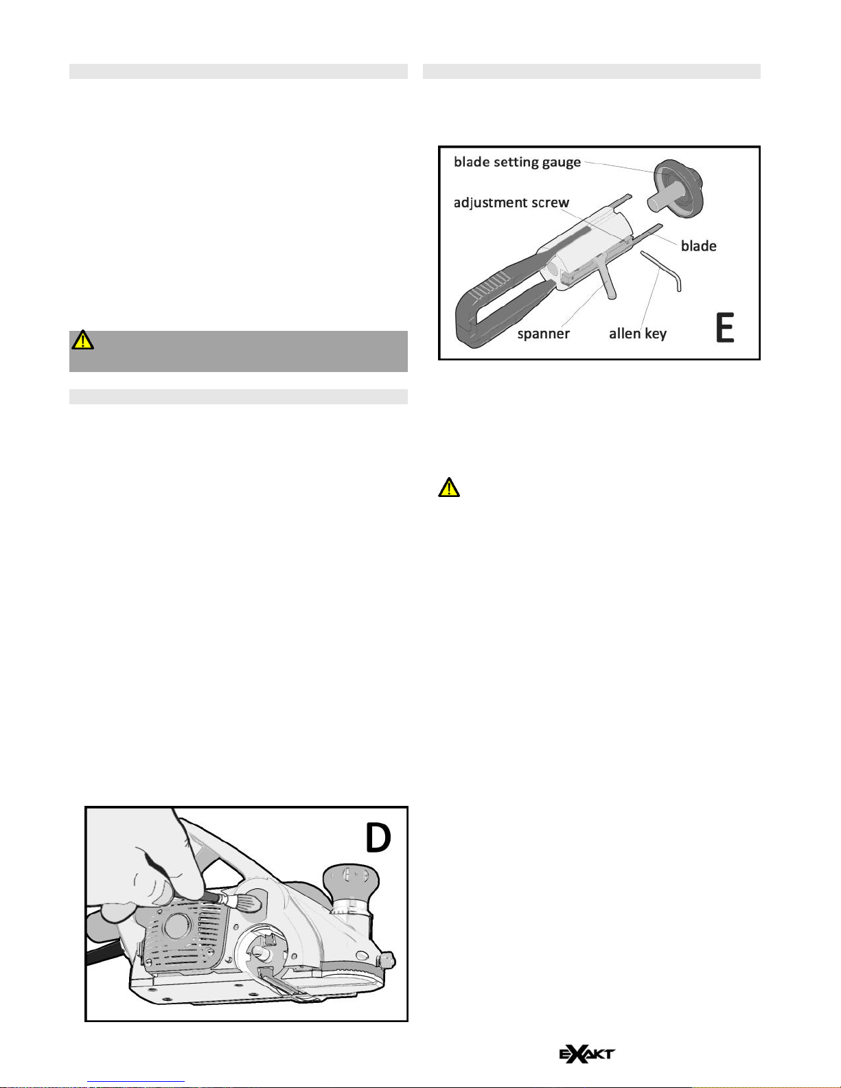
c) If the planing/ sanding waste is ejected around the
working area, rather than through the dust nozzle, it is
likely that the dust bag is full, or the extract fan has
become blocked. To clear the fan, first unplug the tool
and then remove the end cap. Insert a long narrow
brush, such as an artist paint brush, all the way into
the fan to clean (Diagram D)
Changing and setting Planing blades
a) Remove the planing drum from the machine as
described in the Changing Functions section
b) (Refer to diagram E) Loosen the 3 bolts holding the
blade cartridge in place slightly using the spanner to
allow the blade to be slid out (it is not necessary to
remove the cartridge from the drum)
c) Reverse (blade is double sided) or replace the blade
back into the cartridge
WARNING! Use care in handling the blades as they
are very sharp!
d) Introduce the blade setting gauge into one end of the
drum, if required, to help set the blades to the correct
dimension
e) Use the adjustment screws to position the blade
f) Re-tighten the 3 cartridge bolts and remove the blade
setting gauge
g) Replace the drum back into the machine and
withdraw the removal tool
h) Replace and tighten the drum locking nut and end
cap respectively
5 Precision Tools Ltd. 2010
Servicing
EXAKT Precision Tools Ltd.
Tel: +44 (0)1467 633800
Midmill Business Park
Fax: +44 (0)1467 633900
Tumulus Way
Freephone numbers:
Kintore, Inverurie AB51 0TG
D: 0800 180 7063
Scotland, UK
F: 0800 916696
E-mail: info@exaktpt.com
I: 800 930 019
User-replaceable parts
Consumable Items
Part No.
40 grit sanding tube
50 grit sanding tube
60 grit sanding tube
34-0322
34-0321
34-0352
Set of 2 planer blades
34-0323
Dust bag
34-0324
Spare Parts
Part No.
Set of 2 planer cartridges
34-0325
Drum locking nut
44-0168
Set of keys and spanners
34-0326
Fence guide
44-0044
Vacuum adapter
Variable hose coupling
44-0085
44-0213
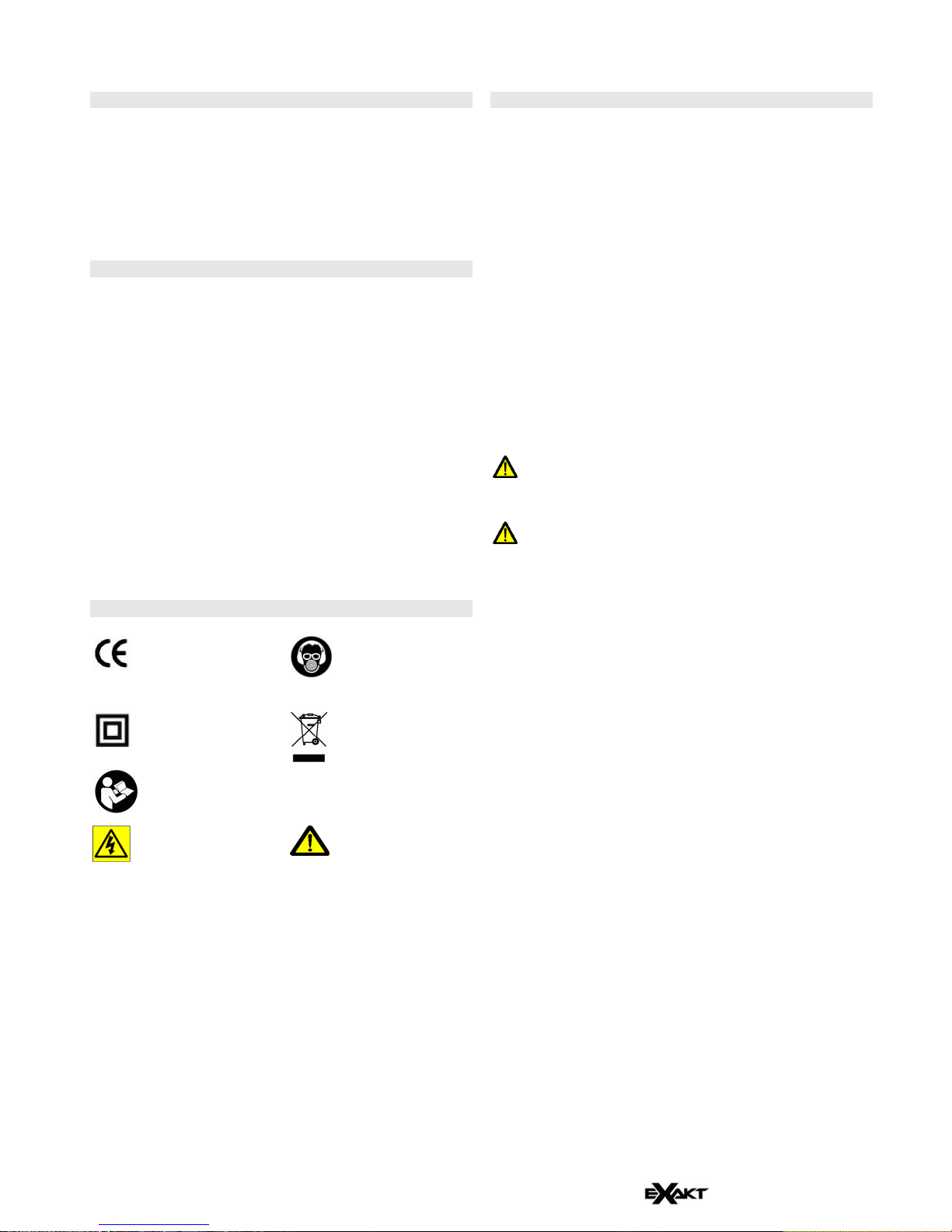
Explanation of Symbols:
Conforms to
European
directives
Wear face mask,
eye protection and
ear protection
Double insulated
appliance
Discard at
recognised
collection point
Read instructions
before use
Product reg. No.
WEE/BH0080UV
Risk of electric
shock
Risk of injury
when instructions
are not followed
Specifications
Motor input power
1200W
Voltage
230v
Current
5.2A
Weight
4.4Kg
Sound pressure level under load
Uncertainty (k)
92.5dB(A)
3dB
Sound power level Lwa under Load
Uncertainty (k)
103.5dB(A)
3dB
Hand arm vibration value
Uncertainty (k)
5.5m/s2
1.5m/s2
The declared vibration total value has been measured in
accordance with a standard test method and may be used
for comparing one tool with another.
The declared vibration total value may also be used in a
preliminary assessment of exposure
WARNING! The vibration emission during actual use
of the power tool can differ from the declared total value
depending on the ways in which the tool is used.
WARNING! There is a need to identify safety
measures to protect the operator that are based on an
estimation of exposure in the actual conditions of use
(taking account of all parts of the operating cycle such as
the times when the tool is switched off and when it is
running idle in addition to trigger time)
 Loading...