

exacqVision LC Series Quick Start Manual

LC-Series Quick Start Guide
www.exacq.com 1 of 2 March 12, 2017, Rev A
Introduction
The LC-Series is part of exacqVision’s series of network video recorders (NVR). The server is pre -installed with exacqVision’s video
management software, and can connect both IP and analog cameras. The server can con nect up to 16 IP cameras and 16 analog
cameras.
Note: You can not replace analog cameras with IP cameras.
Installation
Before turning on the exacqVision LC-Series server, ensure that you meet the following requ irements:
Mounting and operating environment requirements
Mount the exacqVision server in a dust-free, and climate controlled location where the temperature is le ss than 70°F, and the
humidity level is less than 80% non-condensing.
Note: Dust can cause components of the server to overheat, and elevated temperatures can c ontribute to premature hard drive
failures.
You can place a surge suppressor between the camera and the recorder of all outdoor cameras.
If you use an outdoor camera, the server must connect permanently to the ground wire. Ensure that you u se an 18 AWG wire
or larger to make the connection. Label the grounding screw near the power connector w ith the image in Figure 1.
Electrical requirements
For maximum reliability, connect the exacqVision server to an online UPS.
Note: An online UPS filters power surges and dips that can damage the server.
Connect a monitor, a mouse, and a keyboard to the exacqVision server.
Connect the exacqVision server’s Network Interface Card (NIC) to the appropriate network switch ports.
Network connection requirements
If the Video Surveillance System does not have a physically isolated network, connect all the IP cameras and one server NIC to a
dedicated camera VLAN.
Install the cameras manufacturer’s software on a computer, or configure the router so that the exacqVision client can
communicate with the camera subnet. For information on how to configure the network, see Configuring the server.
Camera connections
To connect cameras to the system, complete the following steps:
Connect the analog cameras, PTZ serial cables, or alarm I/O. For more information, see Connections.
Note: Connections vary by model.
Using the camera manufacturer’s software, configure the IP addresses for all the cameras, and rec ord this configuration
information for future reference.
Note: Do not change the username and password until after the server connectivity establishes.
For additional information, see the camera manufacturer’s website, or the
exacqVision IP Camera Quick Start Guide
at
http://www.exacq.com/downloads/ev-ip-quickstart-0311.pdf.
Use the following link to determine the compatibility of a particular camera model and firmware combination wit h exacqVision
servers:
http://www.exacq.com/support/ipcams.php
To test the connectivity between the camera and the server, complete the following step s:
a. Log off of the operating system user account, and log on to the administrator account.
Note: Use the following default username and password:
Username: admin
Password: admin256
b. In the address bar on your i nternet browser, type the camera’s IP address.
c. Press Enter.
Note: If the browser does not display an introductory or logon window, the ca mera is not establishing a connection with the
server. Check the
exacqVision User Manual
, and www.exacq.com/kb for a solution if the problem persists.
Repeat steps one to four for all other camera connections.
Configuration
After you turn on the exacqVision LC-Series Server, the system automatically logs on using the user ac count, and opens the
exacqVision client. If necessary, log on to the administration account using the following de fault credentials:
Username: admin
Password: admin256
Configuring the server
To configure the exacqVision LC-Series server, complete the following steps:
Turn on the server.
Open the exacqVision client application.
From the navigation tree, select System Setup, and select the Net work tab.
Choose one of the following options:
If you install the server on a network that uses static IP addressing, select Static and enter the IP address.
If you install the server on a network using DHCP, select Dynamic . If the information does not automatically configure,
contact your network administrator.
Click Apply.
Repeat this procedure for any additional network ports. For more information on configuring the serve r, see the
exacqVision Start
User Manual
.
Figure 1. Grounding wire
LC-Series Quick Start Guide
www.exacq.com 2 of 2 March 12, 2017, Rev A
Remote access for administrative support
For remote administrative support access to the server, configure Remote Desktop (Windows) or SSH (L inux) on your computer. For
more information, see the following Exacq Knowledge Base articles:
Using remote desktop to manage Windows-based exacqVision servers:
https://www.exacq.com/kb/?kbid=61687
Using Secure Shell (SSH) to manage Linux-based exacqVision servers:
https://www.exacq.com/kb/?kbid=6186
Setting up remote access to the servers
To configure the server through a remote exacqVision client, complete the following steps:
Download the latest exacqVision client software from the Exacq website at: https://www. exacq.com/support/downloads.php
Install the client software on a system administrator computer.
Confirm the connectivity with the server using the ping command and the server IP addres s. If the client PC can not
communicate with the server, contact your network administrator.
Configuring the client
To configure the exacqVision LC-Series client, complete the following steps:
Start the exacqVision client application.
Click the Config (Setup) page icon.
From the navigation tree, select Add System.
Click New, and enter the IP address or hostname of the exacqVision server.
Enter the following username and password:
Username: admin
Password: admin256
Select a connection speed.
Click Apply.
Verify that the server appears in the Systems list, with a status showing Co nnected.
Note: If the server does not connect, but the server connectivity is confirmed, check for anti -virus software on the remote client
machine that may be blocking the communication between the server IP addresses and por ts.
Change the default operating system administration and user accounts. For more information, see the
exacqVision User
Manual
, and www.exacq.com/kb
Configure the system using the
exacqVision User Manual
at http://www.exacq.com/support/specsheets.html
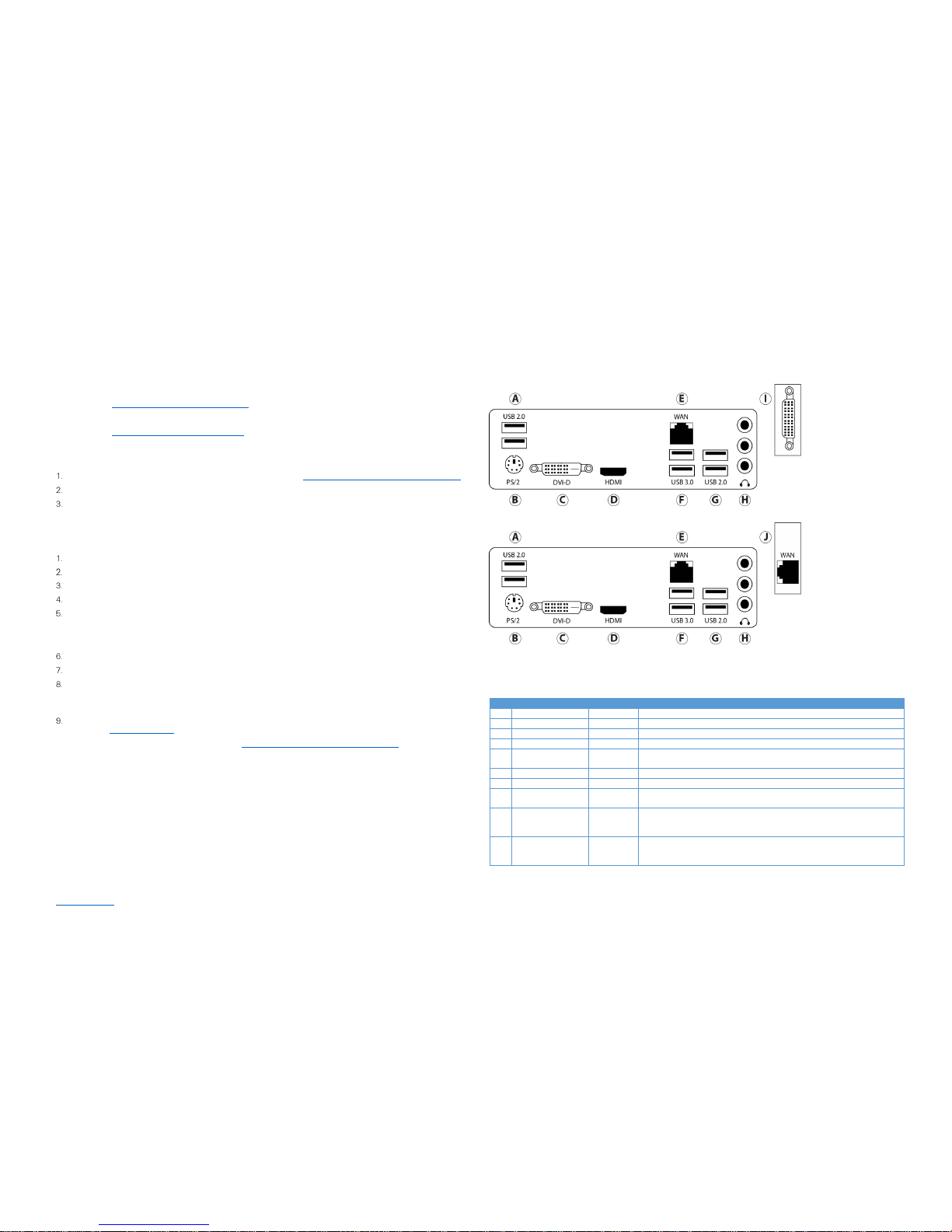
Connections
For information on the exacqVision LC-Series server’s Hybrid Only and IP Only back panels, see F igure 2, Figure 3, and Table 1.
Figure 2. LC-Series Hybrid Only System back panel
Figure 3. LC-Series IP Only System back panel
Note: The cable with the yellow connector, that is included with the system, is for the Vide o out port. For sixteen input systems,
the cable with the yellow connector does not work with the port for inputs 9-16.
Name
No. of Ports
Description
A
USB 2.0
2
USB for use with keyboard, mouse, memory device, or DVD burner
B
PS/2 1 PS/2 for use with keyboard or mouse
C
DVI-D 1 D HDMI 1
E
10/100/1000
Ethernet
1
LAN RJ-45
F
USB 3.0
2
USB3_34, USB keyboard, mouse, memory device, or DVD burner
G
USB 2.0
2
USB_56, USB keyboard, mouse, memory device, or DVD burner
H
Audio In/Out
3
Blue is the line in connection, green is the line out connection, and pink is
the microphone connection.
I
Video In, Video Out*
Audio In for Hybrid
systems
1
8 or 16 video inputs, audio inputs, or video output(s)
J
Secondary
10/100/1000
Ethernet interface
1
For IP only systems
Table 1. LC-Series server back panel
 Loading...