


EWM
HIGHTEC WELDING GmbH
Dr. Günter-Henle-Straße 8 • D-56271 Mündersbach
Fon +49 2680 181-0 • Fax +49 2680 181-244
www.ewm.de • info@ewm.de
GB
Operating instructions
Machines for MIG/MAG welding
WEGA 351, 401, 451, 501, 601
WEGA DRIVE 41, 41L
N. B. These operating instructions must be read before commissioning.
Failure to do so may be dangerous.
Machines may only be operated by personnel who are familiar with the appropriate safety
regulations.
The machines bear the conformity mark and thus comply with the
• EC Low Voltage Directive (2006/95/ EG)
• EC EMC Directive (2004/108/ EG)
In compliance with IEC 60974, EN 60974, VDE 0544 the machines can be used in environments
with an increased electrical hazard.
©
The content of the operating instructions does not constitute grounds for any claims on the part
of the buyer.
The copyright to these operating instructions remains with the manufacturer.
Reprinting, including extracts, only with written approval.
© 2009 Subject to alteration.
Item No.: 099-004934-EWM01
Revised: 21.07.2009

Mündersbach, 25 February 2009
Dear customer,
Thank you for your order.
Premium quality – made in Germany and with a three-year warranty.
The machines from EWM are impressive, with innovative technology, exceptional user-friendliness and
the most up to date inverter and control systems. This makes welding possible that is simple, efficient
and resource-saving as well as being highly economical!
Perfection doesn't happen by coincidence: Every single component is 100% tested and the machine is
“free welded” before it is delivered.
Our comprehensive service offer and the highly de veloped modern EWM quality management system
guarantee worldwide premium quality “Made in Germany” and a three-year warranty.
Continual further development and optimisation has made us Germany’s market leader in the
manufacture of light arc welding machines. We have manufacturing, training and service locations
throughout the world to advise you and provide you with a comprehensi ve range of services.
The accompanying operating instructions contain everything about commi ssioning the machine, notes
regarding safety, maintenance and care, technical data as well as information regarding the warranty. It
is very important to observe all our instructions in order to achieve optimal welding results with the
machine and to ensure many years of safe operation.
Thank you for the trust that you have placed in us. We look forward to a long-term and, above all,
successful partnership with you.
Yours faithfully
EWM HIGHTEC WELDING GmbH
Bernd Szczesny
Executive management

Machine and Company Data
Please enter the EWM machine data and your company’s data in the appropriate fields.
CE
EWM HIGHTEC WELDING GMBH
D-56271 MÜNDERSBACH
TYP:
ART:
SNR:
PROJ:
GEPRÜFT/CONTROL:
Name of Customer / company
Adress
Post code / Place
Country
Stamp / Signature of EWM-distibutor
Date of purchase
Name of Customer / company
Adress
Post code / Place
Country
Stamp / Signature of EWM-distibutor
Date of purchase
3

Contents
Notes on the use of these operating instructions
4 Item No.: 099-004934-EWM01
1 Contents
1 Contents..................................................................................................................................................4
2 Safety instructions.................................................................................................................................8
2.1 Notes on the use of these operating instructions...........................................................................8
2.2 General.........................................................................................................................................10
2.3 Transport and installation.............................................................................................................12
2.3.1 Lifting by crane .............................................................................................................13
2.4 Ambient conditions.......................................................................................................................14
2.4.1 In operation...................................................................................................................14
2.4.2 Transport and storage ..................................................................................................14
3 Technical data.......................................................................................................................................15
3.1 WEGA 351, 401, 451...................................................................................................................15
3.2 WEGA 501, 601...........................................................................................................................16
3.3 WEGA DRIVE 41 L......................................................................................................................17
3.4 WEGA DRIVE 41.........................................................................................................................17
4 Machine description.............................................................................................................................18
4.1 WEGA 351, 401, 451K.................................................................................................................18
4.1.1 Front view.....................................................................................................................18
4.1.2 Rear view......................................................................................................................20
4.2 WEGA 351, 401, 451, 501, 601 D ...............................................................................................22
4.2.1 Front view.....................................................................................................................22
4.2.2 Rear view......................................................................................................................24
4.3 WEGA DRIVE 41 L......................................................................................................................26
4.3.1 Front view.....................................................................................................................26
4.3.2 Rear view......................................................................................................................27
4.4 WEGA DRIVE 41.........................................................................................................................28
4.4.1 Front view.....................................................................................................................28
4.4.2 Inside view....................................................................................................................29
5 Functional characteristics...................................................................................................................30
5.1 Machine control – Operating elements........................................................................................30
5.1.1 Welding machine control M1.02...................................................................................30
5.1.1.1 Internal operating elements...........................................................................31
5.1.1.2 Setting the operating point (welding output) .................................................32
5.1.1.3 Welding parameter ignition time "tZn" diagram.............................................32
5.1.2 M2.20 welding machine control....................................................................................33
5.1.2.1 Setting the operating point (welding output) .................................................35
5.1.2.2 Setting the operating mode and runtime parameters....................................35
5.1.2.3 Setting the expert parameters.......................................................................36
5.1.2.4 Welding parameter ignition time "tZn" diagram.............................................36
5.1.3 M2.40 welding machine control....................................................................................37
5.1.3.1 Select JOB number (welding task)................................................................39
5.1.3.2 Setting the operating point (welding output) .................................................40
5.1.3.3 Setting the wire correction.............................................................................40
5.1.3.4 Setting the operating mode and runtime parameters....................................41
5.1.3.5 Setting the expert parameters.......................................................................42
5.1.3.6 Welding parameter ignition time "tZn" diagram.............................................42
5.1.3.7 Reset to factory settings................................................................................43
5.1.3.8 Check the machine type setting....................................................................43
5.1.3.9 Setting the machine type...............................................................................43
5.1.3.10 Explanation of symbols ...............................................................................44

Contents
Notes on the use of these operating instructions
Item No.: 099-004934-EWM01 5
5.2
MIG/MAG functional sequences / operating modes....................................................................45
5.2.1 Explanation of signs and functions...............................................................................45
5.2.2 Non-latched operation..................................................................................................46
5.2.3 Latched operation.........................................................................................................47
5.2.4 Spots ............................................................................................................................48
5.2.5 Interval..........................................................................................................................49
5.2.6 MIG/MAG automatic cut-out.........................................................................................49
6 Commissioning ....................................................................................................................................50
6.1 General........................................................................................................................................50
6.2 Area of application – proper usage..............................................................................................50
6.3 Installation....................................................................................................................................51
6.4 Mains connection.........................................................................................................................51
6.5 Machine cooling...........................................................................................................................51
6.6 Coolant.........................................................................................................................................52
6.6.1 List of coolants..............................................................................................................52
6.6.2 Adding coolant..............................................................................................................52
6.7 Workpiece lead, general..............................................................................................................53
6.8 Welding torch and workpiece line connection .............................................................................53
6.8.1 Intermediate tube package connection........................................................................56
6.8.1.1 Wire feed unit................................................................................................56
6.8.1.2 Welding machine...........................................................................................58
6.9 Shielding gas supply....................................................................................................................59
6.9.1 Connecting the shielding gas supply............................................................................59
6.9.2 Gas test or "rinse tube package"..................................................................................60
6.9.3 Setting the shielding gas quantity.................................................................................60
6.10 Inserting the wire electrode..........................................................................................................61
6.10.1 Fixing the wire spool retainer (pre-tension adjustment) ...............................................61
6.10.2 Spool brake setting.......................................................................................................62
6.10.3 Inserting the wire spool ................................................................................................63
6.10.4 Changing the wire feed rollers......................................................................................64
6.10.5 Inching the wire electrode ............................................................................................65
7 Maintenance and testing.....................................................................................................................66
7.1 General........................................................................................................................................66
7.2 Cleaning.......................................................................................................................................66
7.3 Test..............................................................................................................................................67
7.3.1 Test equipment.............................................................................................................67
7.3.2 Scope of the test...........................................................................................................68
7.3.3 Visual inspection...........................................................................................................68
7.3.4 Measuring the open circuit voltage...............................................................................68
7.3.5 Measurement of insulation resistance..........................................................................68
7.3.6 Measuring the leakage current (protective conductor and contact current).................69
7.3.7 Measurement of protective conductor resistance ........................................................69
7.3.8 Functional test of the welding machine........................................................................69
7.3.9 Documentation of the test ............................................................................................69
7.4 Repair Work.................................................................................................................................70
7.5 Disposing of equipment...............................................................................................................71
7.5.1 Manufacturer's declaration to the end user..................................................................71
7.6 Meeting the requirements of RoHS.............................................................................................71
8 Warranty................................................................................................................................................72
8.1 General Validity............................................................................................................................72
8.2 Warranty Declaration...................................................................................................................73

Contents
Notes on the use of these operating instructions
6 Item No.: 099-004934-EWM01
9
Operating problems, causes and remedies.......................................................................................74
9.1 Customer checklist.......................................................................................................................74
9.2 Resetting the control (Reset all)...................................................................................................74
9.3 Check the machine type setting...................................................................................................75
9.4 Setting the machine type..............................................................................................................75
10 Accessories, options ...........................................................................................................................76
10.1 General accessories ....................................................................................................................76
10.2 Options.........................................................................................................................................77
10.3 Wire feed rollers...........................................................................................................................78
10.3.1 Wire feed rollers for aluminium wire.............................................................................78
10.3.2 Wire feed rollers for cored wire.....................................................................................78
10.3.3 Conversion sets............................................................................................................78
11 Circuit diagrams...................................................................................................................................79
11.1 WEGA KG, KW (M1.02)...............................................................................................................79
11.2 WEGA KG, KW (M2.20/M2.40)....................................................................................................80
11.3 WEGA DW, DG............................................................................................................................81
11.4 WEGA DRIVE 41 (L) M1.02.........................................................................................................82
11.5 WEGA DRIVE 41 (L) M220/M2.40...............................................................................................83
12 Appendix A............................................................................................................................................84
12.1 Declaration of Conformity.............................................................................................................84
13 Appendix B............................................................................................................................................85
13.1 Recommended settings ...............................................................................................................85

Contents
Notes on the use of these operating instructions
Item No.: 099-004934-EWM01 7

Safety instructions
Notes on the use of these operating instructions
8 Item No.: 099-004934-EWM01
2 Safety instructions
2.1 Notes on the use of these operating instructions
NOTE
Special technical points which users must observe.
• Notes include the "NOTE" keyword in the heading without a general warning symbol.
• Notes are highlighted using a "hand" symbol at the edge of the page.
CAUTION
Working and operating procedures which must be followed precisely to avoid damaging
or destroying the product.
• The safety information includes the "CAUTION" keyword in its heading without a general
warning symbol.
• The hazard is explained using a symbol at the edge of the page.
CAUTION
Working or operating procedures which must be closely observed to prevent possible
minor personal injury.
• The safety information includes the "CAUTION" keyword in its heading with a general
warning symbol.
• The risk is explained using a symbol on the edge of the page.
WARNING
Working or operating procedures which must be closely observed to prevent serious
and even fatal injuries.
• Safety notes include the "WARNING" keyword in the heading with a general warning
symbol.
• The hazard is also highlighted using a symbol on the edge of the page.
DANGER
Working or operating procedures which must be closely observed to prevent imminent
serious and even fatal injuries.
• Safety notes include the "DANGER" keyword in the heading with a general warning symbol.
• The hazard is also highlighted using a symbol on the edge of the page.

Safety instructions
Notes on the use of these operating instructions
Item No.: 099-004934-EWM01 9
Instructions and lists detailing step-by-step actions in given situatio ns can be recognised by bullet points,
e.g.:
• Insert the welding current lead socket into the relevant socket and lock.
Symbol Description
Press
Do not press
Turn
Switch

Safety instructions
General
10 Item No.: 099-004934-EWM01
2.2 General
WARNING
Risk of accidents if these safety instructions are not observed!
Non-observance of these safety instructions is potentially fatal!
• Carefully read the safety information in this manual!
• Observe the accident prevention regulations in your country.
• Inform persons in the working area that they must observe the regulations!
CAUTION
Obligations of the operator!
In the European Economic Area (EEA), the relevant national version of the basic
guidelines must be followed and observed!
• National version of the basic guidelines (89/391/EEC) as well as the relevant individual
guidelines.
• In particular the Directive (89/655/EEC) on the minimum regulations for safety and health
protection when staff members are using equipment during work.
• The accident prevention regulations of the relevant country (e.g. in Germany, BGV D 1).
• Check at regular intervals that users are working in a safety-conscious wa y!
Damage due to the use of non-genuine parts!
The manufacturer's warranty becomes void if non-genuine parts are used!
• Only use system components and options (power sources, welding torches, electrode
holders, remote controls, spare parts and replacement parts, etc.) from our range of
products!
• Only insert and lock accessory components into the relevant connection socket when the
machine is switched off.
CAUTION
Noise exposure!
Noise exceeding 70 dBA can cause permanent hearing damage!
• Wear suitable ear protection!
• Persons located within the working area must wear suitable ear protection!
DANGER
Electric shock!
Welding machines use high voltages which can result in potentially fatal electric shocks
and burns on contact. Even low voltages can cause you to get a shock and lead to
accidents.
• Do not touch any live parts in or on the machine!
• Connection cables and leads must be free of faults!
• Switching off alone is not sufficient! Wait for 2 minutes until the capacitors have discharged.
• Place welding torch and stick electrode holder on an insulated surf ace!
• The unit should only be opened by specialist staff after the mains plug has been unplugged!
• Only wear dry protective clothing!

Safety instructions
General
Item No.: 099-004934-EWM01 11
DANGER
Electromagnetic fields!
The power source may cause electrical or electromagnetic fields to be produced which
could affect the correct functioning of electronic equipment such as IT or CNC devices,
telecommunication lines, power cables, signal lines and pacemakers.
• Observe the maintenance instructions! (see Maintenance and Testing chapter)
• Unwind welding lines completely!
• Shield devices or equipment sensitive to radiation accordingly!
• The correct functioning of pacemakers may be affected (obtain advice from a doctor if
necessary).
Do not carry out any unauthorised repairs or modifications!
To avoid injury and equipment damage, the unit must only be repaired or modified by
specialist, skilled persons!
The warranty becomes null and void in the event of unauthorised interference.
• Appoint only skilled persons for repair work (trained service personnel)!
WARNING
Risk of injury due to radiation or heat!
Arc radiation results in injury to skin and eyes.
Contact with hot workpieces and sparks results in burns.
• Wear dry protective clothing (e.g. welding shield, gloves, etc.) according to the relevant
regulations in the country in question!
• Protect persons not involved in the work against arc beams and the risk of glare using safety
curtains!
Explosion risk!
Apparently harmless substances in closed containers may generate excessive pressur e
when heated.
• Move containers with inflammable or explosive liquids away from the working area!
• Never heat explosive liquids, dusts or gases by weldi ng or cutting!
Smoke and gases!
Smoke and gases can lead to breathing difficulties and poisoning. In addition, solvent
vapour (chlorinated hydrocarbon) may be converted into poisonous phosgene due to the
ultraviolet radiation of the arc!
• Ensure that there is sufficient fresh air!
• Keep solvent vapour away from the arc beam field!
• Wear suitable breathing apparatus if appropriate!
Fire hazard!
Flames may arise as a result of the high temperatures, stray sparks, glowing-hot parts
and hot slag produced during the welding process.
Stray welding currents can also result in flames forming!
• Check for fire hazards in the working area!
• Do not carry any easily flammable objects such as matches or lighters.
• Keep appropriate fire extinguishing equipment to hand in the working area!
• Thoroughly remove any residue of flammable substances from the workpiece before starting
welding.
• Only continue work on welded workpieces once they have cooled down.
Do not allow to come into contact with flammable material!
• Connect welding leads correctly!

Safety instructions
Transport and installation
12 Item No.: 099-004934-EWM01
2.3 Transport and installation
CAUTION
Equipment damage when not operated in an upright position!
The units are designed for operation in an upright position!
Operation in non-permissible positions can cause equipment damage.
• Only transport and operate in an upright position!
CAUTION
Risk of tipping!
There is a risk of the machine tipping over and injuring persons or being damaged itself
during movement and set up. Tilt resistance is guaranteed up to an angle of 10°
(according to IEC 60974-1, -3, -10).
• Set up and transport the machine on level, solid ground.
• Secure add-on parts using suitable equipment.
Damage due to supply lines not being disconnected!
During transport, supply lines which have not been disconnected (mains supply leads,
control leads, etc.) may cause hazards such as connected equipment tipping over and
injuring persons!
• Disconnect supply lines!
WARNING
Incorrect handling of shielding gas cylinders!
Incorrect handling of shielding gas cylinders can result in serious and even fatal injury.
• Observe the instructions from the gas manufacturer and in any relevant regulations
concerning the use of compressed air!
• Place shielding gas cylinders in the holders provided for them and secure with fixing
devices.
• Avoid heating the shielding gas cylinder!

Safety instructions
Transport and installation
Item No.: 099-004934-EWM01 13
2.3.1 Lifting by crane
DANGER
Risk of injury during lifting by crane!
When lifting the equipment by crane, serious injuries can be inflicted by falling
equipment or add-on units.
• Transport on all lifting lugs at the same time
(see Fig. Lifting principle)!
• Ensure that there is an even load distribution! Only use ring
chains or suspension ropes of the same length!
• Observe the lifting principle (see Fig.)!
• Remove all accessory components before lifting
(e.g. shielding gas cylinders, tool boxes, wire feed units, etc.)!
• Avoid jerky movements when raising or lowering!
• Use shackles and load hooks of the appropriate size!
min. 1 m
75 °
Fig. Lifting principle
Risk of injury due to unsuitable ring screws!
In case of improper use of ring screws or the use of unsuitable ring screws, persons can
be seriously damaged by falling equipment or add-on components!
• The ring screw must be completely screwed in!
• The ring screw must be positioned flat onto and in full contact with the supporting surfaces!
• Check that the ring screws are securely fastened before use and check for any damag e
(corrosion, deformation)!
• Do not use or screw in damaged ring screws!
• Avoid lateral loading of the ring screws!
Safety instructions
Ambient conditions
14 Item No.: 099-004934-EWM01
2.4 Ambient conditions
CAUTION
Equipment damage due to dirt accumulation!
Unusually high quantities of dust, acid, corrosive gases or substances may damage the
equipment.
• Avoid high volumes of smoke, vapour, oil vapour and grinding dust!
• Avoid ambient air containing salt (sea air)!
Non-permissible ambient conditions!
Insufficient ventilation results in a reduction in performance and equipment damage.
• Observe the ambient conditions!
• Keep the cooling air inlet and outlet clear!
• Observe the minimum distance of 0.5 m from obstacles!
Installation site!
The machine must not be operated in the open air and must only be set up and operated
on a suitable, stable and level base!
• The operator must ensure that the ground is non-slip and level, and provide sufficient
lighting for the place of work.
• Safe operation of the machine must be guaranteed at all times.
2.4.1 In operation
Temperature range of the ambient air:
• -20 °C to +40 °C
Relative air humidity:
• Up to 50% at 40 °C
• Up to 90% at 20 °C
2.4.2 Transport and storage
Storage in an enclosed space, temperature range of the ambient air:
• -25 °C to +55 °C
Relative air humidity
• Up to 90% at 20 °C

Technical data
WEGA 351, 401, 451
Item No.: 099-004934-EWM01 15
3 Technical data
3.1 WEGA 351, 401, 451
WEGA series 351 401 451
Switching steps
16 24 (2x12) 24 (2x12)
Welding current setting range
30 A–350 A 30 A–400 A 30 A–450 A
Duty cycle at 40°C ambient temperature
45% DC
350 A 400 A 450 A
60% DC
300 A 330 A 400 A
100% DC
230 A 255 A 310 A
Duty cycle at 20°C ambient temperature
52.5% DC
350 A 400 A 450 A
70% DC
300 A 330 A 400 A
100% DC
250 A 275 A 335 A
Open circuit voltage
15.5-41 V 15.5-45 V 16.5-45 V
Mains connection lead
H07RN-F4G4
Mains voltage (tolerances)
3 x 400 V (+/- 15%)
Frequency
50/60 Hz
Mains fuse (slow-blow safety
fuse)
3 x 25 A
Max. connected power
16.0 kVA 19.2 kVA 23.2 kVA
Workpiece lead
50 mm² 70 mm² 70 mm²
Recommended generator
power
21.5 kVA 26 kVA 32 kVA
Cosϕ
0.95
Weight KG
130 kg 145 kg 150 kg
Weight KW
150 kg 165 kg 170 kg
Weight DG
125 kg 139 kg 144 kg
Weight DW
145 kg 159 kg 164 kg
Dimensions (L x W x H in mm)
1100 x 550 x 940
Insulation class/protection
classification
H/IP 23
Ambient temperature
-20°C to +40°C
Machine/torch cooling
Fan, gas or water, depending on type
Constructed to standards
IEC 60974-1, -5, -10 /
/
Specifications of internal wire-feed unit (only KG, KW):
WF speed
0.5–24 m/min
Standard WF rollers
1.0 + 1.2 mm (for steel wire)
Drive
4-roller (37mm)
Torch connection
Welding torch central connection (Euro)
Specifications of internal cooling unit (only KW, DW):
Max. tank capacity
9 l
Flow rate (max.)
5 l/min 5 l/min 5 l/min
Initial pressure (max.)
3.5 bar 3.5 bar 3.5 bar

Technical data
WEGA 501, 601
16 Item No.: 099-004934-EWM01
3.2 WEGA 501, 601
WEGA series 501DW 601DW
Switching steps
36 (3x12)
Welding current setting range
50 - 500 A 50 - 600A
Duty cycle at 40C ambient temperature
45% DC
500 A 600 A
60% DC
435 A 520 A
100% DC
335 A 400 A
Duty cycle at 20C ambient temperature
52,5% DC
500 A 600 A
70% DC
435 A 520 A
100% DC
365 A 440 A
Open circuit voltage
16,5 - 49,5 V 16,5 - 57,5 V
Mains voltage (tolerances)
3 x 400V (+/- 15%)
Frequency
50/60Hz
Mains fuse
(safety fuse, slow-blow)
3x32A
Max. connected power
27,5 kVA 36,7 kVA
Workpiece lead
95 mm
2
95 mm2
Recommended generator
power
32 kVa 50 kVA
Cosϕ
0,95
Weight
200 kg 228 kg
Dimensions (L/W/H in mm)
960 x560 x 1010
Insulation class/protection
classification
H/IP 23
Ambient temperature
-20°C to +40°C
Machine/torch cooling
Fan/water
Constructed to standards
IEC 60974-1, -5, -10 /
/
Internal cooling unit data
Max. tank capacity
9 l
Flow rate (max.)
5l/min
Initial pressure (max.)
3.5bar

Technical data
WEGA DRIVE 41 L
Item No.: 099-004934-EWM01 17
3.3 WEGA DRIVE 41 L
WEGA DRIVE 41 L
Supply voltage
42 V AC
Max. welding current at 60% DC
520 A
Wire-feed speed
0.5 m/min to 24 m/min
Standard WF roller fitting
1.0 + 1.2 mm (for steel wire)
Drive
4-roller (37mm)
Torch connection
Welding torch central connection (Euro)
Protection classification
IP 23
Ambient temperature
-20°C to +40°C
Dimensions (L x W x H) [mm]
690 x 300 x 410
Weight
approx. 18 kg
Constructed to standards
IEC 60974-1, -5, -10 /
3.4 WEGA DRIVE 41
WEGA DRIVE 41
Supply voltage
42 V AC
Max. welding current at 60% DC
520 A
Wire-feed speed
0.5 m/min to 24 m/min
Standard WF roller fitting
1.0 + 1.2 mm (for steel wire)
Drive
4-roller (37 mm)
Torch connection
Welding torch central connection (Euro)
Protection classification
IP 23
Ambient temperature
-20°C to +40°C
Dimensions (L x W x H) [mm]
680 x 460 x 265
Weight
approx. 24 kg
Constructed to standards
IEC 60974-1, -5, -10 /

Machine description
WEGA 351, 401, 451K
18 Item No.: 099-004934-EWM01
4 Machine description
4.1 WEGA 351, 401, 451K
4.1.1 Front view
Figure 4-1

Machine description
WEGA 351, 401, 451K
Item No.: 099-004934-EWM01 19
Item Symbol Description 0
1
Main switch, machine on/off
2
Step switch, welding voltage "coarse"
3
Step switch, welding voltage
4 Operating elements (see chapter Function specification)
5
Central connection for welding torch (Euro)
Integrated welding current, shielding gas and torch trigger
6
Connection socket, workpiece lead
"Hard" choke tapping
7
Connection socket, workpiece lead
"Medium" choke tapping
8
Connection socket, workpiece lead
Choke tapping "soft"
9
Key button, automatic cut-out of coolant pump
Press to reset a triggered fuse
10
Rapid-action closure coupling, red (coolant return)
11
Rapid-action closure coupling, blue (coolant supply)
12 Coolant tank
13 Transport bar
14 Cooling air inlet
15 Conveyor rolls, guide castors
16
Lifting lug
17 Conveyor rolls, fixed castors
NOTE
Step switch, "coarse" welding voltage not applicable with WEGA 351

Machine description
WEGA 351, 401, 451K
20 Item No.: 099-004934-EWM01
4.1.2 Rear view
Figure 4-2

Machine description
WEGA 351, 401, 451K
Item No.: 099-004934-EWM01 21
Item Symbol Description 0
1 Wire feed unit cover lock
2 Mains connection lead
3 Safety chain
4
42V/4A
Key button, automatic cutout
Wire feed motor supply voltage fuse
(press to reset a triggered fuse)
5
Button, Automatic cut-out of fan motor
Press to reset tripped circuit breaker
6
Connecting nipple G¼, shielding gas connection
7 Bracket for shielding gas cylinder
8 Cooling air outlet

Machine description
WEGA 351, 401, 451, 501, 601 D
22 Item No.: 099-004934-EWM01
4.2 WEGA 351, 401, 451, 501, 601 D
4.2.1 Front view
Figure 4-3

Machine description
WEGA 351, 401, 451, 501, 601 D
Item No.: 099-004934-EWM01 23
Item Symbol Description 0
1
Wire feed unit
2
Lifting lug
3 Carrying handle
4
Main switch, machine on/off
5
Step switch, welding voltage "coarse"
6
Step switch, welding voltage
7
Connection socket, workpiece lead
"Hard" choke tapping
8
Connection socket, workpiece lead
"Medium" choke tapping
9
Connection socket, workpiece lead
Choke tapping "soft"
10 Conveyor rolls, fixed castors
11 Conveyor rolls, guide castors
12 Cooling air inlet
13
Signal light, Functional error
On when excess temperature detected
14
Key button, automatic cut-out of coolant pump
Press to reset a triggered fuse
15
Coolant tank cap
16 Coolant tank
NOTE
Step switch, "coarse" welding voltage not applicable with WEGA 351
Coolant tank only for machines fitted with water cooling (DW)

Machine description
WEGA 351, 401, 451, 501, 601 D
24 Item No.: 099-004934-EWM01
4.2.2 Rear view
6
6
7
7
4
4
3
3
2
2
1
1
10
10
5
5
9
9
14
11
11
12
12
8
8
13
Figure 4-4

Machine description
WEGA 351, 401, 451, 501, 601 D
Item No.: 099-004934-EWM01 25
Item Symbol Description 0
1
42V/4A
Key button, automatic cutout
Wire feed motor supply voltage fuse
(press to reset a triggered fuse)
2
7-pole connection socket
Wire feed unit control lead
3 Mains connection cable
4
Button, Automatic cut-out of fan motor
Press to reset tripped circuit breaker
5
Earth cable connecting nipple
Connection of green-yellow earth cable from the intermediate tube package
6
Rapid-action closure coupling, red (coolant return)
7
Rapid-action closure coupling, blue (coolant supply)
8
Connector plug, welding current "+"
Welding current connection on wire feed unit
9
Intermediate tube package strain relief
10 Safety chain
11 Cooling air outlet
12 Bracket for shielding gas cylinder
13
Coolant tank cap
14 Coolant tank
NOTE
Coolant tank only for machines fitted with water cooling (DW)
Machine description
WEGA DRIVE 41 L
26 Item No.: 099-004934-EWM01
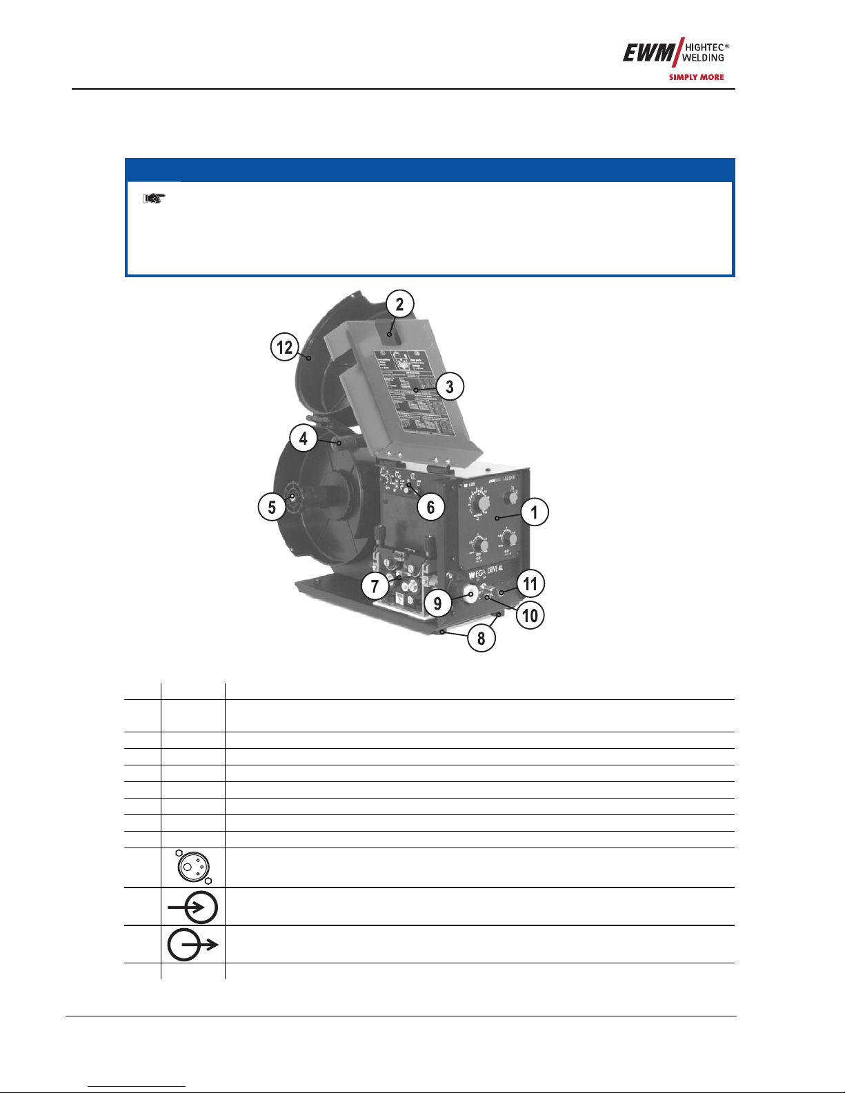
4.3 WEGA DRIVE 41 L
4.3.1 Front view
NOTE
Internal operating elements for gas test, current test and wire inching are only present in
machines with M1.02 control.
In machines with M2.20 and M2.40 control, these operating elements are integrated into the
machine control. Only machines with M2.40 control possess a JOB-List and therefore have the
appropriate sticker attached.
Figure 4-5
Item Symbol Description 0
1 Machine control
See Machine control – operating elements chapter
2 Wire feed unit cover lock
3 Label, Wire feed parts subject to wear
4 Carrying handle
5 Spool holder
6 Operating elements (see chapter Function specification)
7 Wire delivery unit
8
Rubber feet
9
Central connection for welding torch (Euro)
Integrated welding current, shielding gas and torch trigger
10
Rapid-action closure coupling, red (coolant return)
11
Rapid-action closure coupling, blue (coolant supply)
12 Cover of the wire spool

Machine description
WEGA DRIVE 41 L
Item No.: 099-004934-EWM01 27
4.3.2 Rear view
Figure 4-6
Item Symbol Description 0
1
7-pole connection socket
Wire feed unit control lead
2
Earth cable connecting nipple
Connection of green-yellow earth cable from the intermediate tube package
3
Connecting nipple G¼, shielding gas connection
4
Connector plug, welding current "+"
Welding current connection on wire feed unit
5
Rapid-action closure coupling, blue (coolant supply)
6
Rapid-action closure coupling, red (coolant return)
7
Intermediate tube package strain relief
8
Rubber feet

Machine description
WEGA DRIVE 41
28 Item No.: 099-004934-EWM01
4.4 WEGA DRIVE 41
4.4.1 Front view
Figure 4-7
Item Symbol Description 0
1 Slide latch, lock for the protective cap
2 Recessed grip for opening the cap
3 Label, Wire feed parts subject to wear
4 Damper/support for the cover
5 Carrying handle
6 Machine control
See Machine control – operating elements chapter
7 Spool holder
8
Rubber feet
9
Central connection for welding torch (Euro)
Integrated welding current, shielding gas and torch trigger
10
Rapid-action closure coupling, red (coolant return)
11
Rapid-action closure coupling, blue (coolant supply)

Machine description
WEGA DRIVE 41
Item No.: 099-004934-EWM01 29
4.4.2 Inside view
NOTE
Internal operating elements for gas test, current test and wire inching are only present in
machines with M1.02 control.
In machines with M2.20 and M2.40 control, these operating elements are integrated into the
machine control. Only machines with M2.40 control possess a JOB-List and therefore have the
appropriate sticker attached.
Figure 4-8
Item Symbol Description 0
1 Spool holder
2 Sticker, JOB List
3 Wire delivery unit
4
Connecting nipple G¼, shielding gas connection
5
7-pole connection socket
Wire feed unit control lead
6
Earth cable connecting nipple
Connection of green-yellow earth cable from the intermediate tube package
7
Rapid-action closure coupling, blue (coolant supply)
8
Connector plug, welding current "+"
Welding current connection on wire feed unit
9
Rapid-action closure coupling, red (coolant return)
10 Intermediate tube package strain relief
11 Operating elements (see chapter Function specifi cation)
Functional characteristics
Machine control – Operating elements
30 Item No.: 099-004934-EWM01
5 Functional characteristics
5.1 Machine control – Operating elements
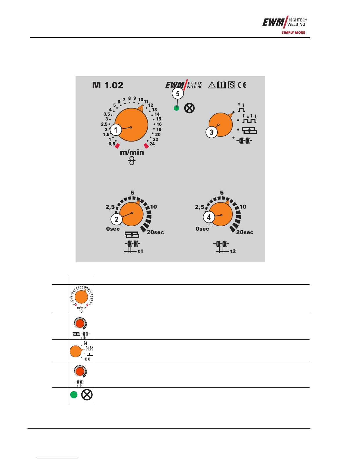
5.1.1 Welding machine control M1.02
Figure 5-1
Item Symbol Description 0
1
Rotary dial, Wire speed setting
Infinite adjustment of the wire speed.
2
0sec
5
10
20sec
2,5
t1
Rotary dial, Spot and interval times
Infinite adjustment of the welding time (0-20s) in "Spots and interval" operating mode
3
"Operating mode" selector switch
Changeover between non-latched, latched, spot, interval
4
0sec
5
10
20sec
2,5
t2
0sec
5
10
20sec
2,5
t2
Rotary dial, Pause time
Infinite adjustment of the pause time (0–20s) in "Interval" operating mode
5
Ready for operation signal light
Signal light on when the machine is switched on and ready for operation

Functional characteristics
Machine control – Operating elements
Item No.: 099-004934-EWM01 31
5.1.1.1 Internal operating elements
NOTE
In decompact machines in combination with M1.02 (& M1.01), the internal operating
elements are located in the wire feed unit.
(see the chapter "Machine description" )
CAUTION
For the following processes the cover must be removed; to protect the machine it is
essential that the cover is fitted back into position afterwards.
• Unlock the right-hand cover on the machine.
• Tilt the cover forwards, then remove upwards.
There are other operating elements for parameter setting on the machine.
Figure 5-2
All details in percent relate to the values stored in the characteristics.
Item Symbol Description 0
1
0
-15
-30
+15
+30
Rotary dial, Wire creep (optional)
+/- 30%
2
Key Button, Wire inching
Currentless wire inching
3
Trimmer, Wire burn-back
+/- 50%
4
"Gas post-flow time" trimmer
Setting range 0.2-10 s
5
Key button, Gas test
Currentless gas test

Functional characteristics
Machine control – Operating elements
32 Item No.: 099-004934-EWM01
5.1.1.2 Setting the operating point (welding output)
This control works according to the twin-knob operation principle. To set the operating point, only the wire
speed and the welding voltage need to be set according to the material and the electrode diameter.
Operating
element
Action Result
Wire speed setting
Welding voltage setting
5.1.1.3 Welding parameter ignition time "tZn" diagram
NOTE
In the ignition time, the wire feed continues to run at creep speed after the arc is ignited;
the ignition behaviour is improved with the optimum setting.
The process described below is always used if there is a pause between welding processes of
not less than 1.5 seconds.
Figure 5-3
Legend with an explanation of symbols can be found in the MIG/MAG function sequences /
operating modes chapter.

Functional characteristics
Machine control – Operating elements
Item No.: 099-004934-EWM01 33
5.1.2 M2.20 welding machine control
Figure 5-4
Item Symbol Description 0
1
Button, Wire inching
For inching the wire electrode when changing the wire spool
(speed = 6.0 m/min, constant).
The welding wire is inched into the tube package with the current off and without gas
being expelled.
This ensures a high degree of safety for the welder by preventing accidental ignition of
the arc.
2
Button, Gas test
The welding voltage and wire feed remain off when testing and setting the gas flow.
Pressing the key button once causes shielding gas to flow for approx. 25 second s. The
button can be pressed again at any time to cancel the process.
3
Signal light, Wire speed
Lights when the wire speed is shown on the display.
4
Current signal light
Lights when the current is shown on the display.
5
Rotary dial, Wire speed/welding parameter setting
Continuous adjustment of the wire speed or welding current and setting of runtime
parameters such as gas post-flows, wire burn-back, etc.
Key button, Operating mode
Non-latched
6
Latched

Functional characteristics
Machine control – Operating elements
34 Item No.: 099-004934-EWM01
Item Symbol Description 0
MIG spots (parameter selection t1 is carried out using the "Runtime
parameters" button, setting on the "Rotary transducer".
Interval (parameter selection, t1 = pulse time, t2 = pulse pause, carried out
using "Runtime parameter" button, setting on the "Rotary transducer".
"Runtime parameters" button
The parameters are set on the rotary transducer
Gas post-flow time (0.0 s to 10.0 s)
Wire burn-back (-50% to +50%)
Spot time / pulse time (0.1 s to 5.0 s)
7
Pulse pause (0.1 s to 2.0 s)
8
Display, Top
Displays welding voltage or person who designated the runtime parameters
9
Display, Down
Display of wire feed speed, welding current and runtime parameters.
10
Signal light, HOLD
Lit: Display shows the last parameters used for welding.
Not lit: Display shows the setpoint values or current values during welding.

Functional characteristics
Machine control – Operating elements
Item No.: 099-004934-EWM01 35
5.1.2.1 Setting the operating point (welding output)
This control works according to the twin-knob operation principle. To set the operating point, only the wire
speed and the welding voltage need to be set according to the material and the electrode diameter.
Operating
element
Action Result
Wire speed setting
Welding voltage setting
5.1.2.2 Setting the operating mode and runtime parameters
NOTE
The parameter values set are preset in the JOB and can be modified if necessary.
Operating
element
Action Result
Select operating mode:
Non-latched
Latched
Spots
n x
Interval
Select welding parameter:
Set gas post-flow time "GnS"
(0.0 s to 10.0 s)
Set wire burn-back time "drb" (-50% to 50%)
Spot/interval time "t1" (0.1 s to 5.0 s)
Interval/pause "t2" (0.1 s to 2.0 s)
n x
The selected parameter is shown on the display
Set the parameter chosen

Functional characteristics
Machine control – Operating elements
36 Item No.: 099-004934-EWM01
5.1.2.3 Setting the expert parameters
NOTE
The parameter values set are preset in the JOB and can be modified if necessary.
Operating
element
Action Result
1 x
1 x
2 x
Select expert parameters.
The key combination must be pressed within 3 seconds.
Select expert parameters:
Gas pre-flow time "GvS" (0 s to 10 s)
Wire creep speed "On" 0.5 – 24 m/min
Ignition time "tZn" (0 ms to 500 ms)
n x
The selected parameter is shown on the display.
Set the parameter chosen.
5.1.2.4 Welding parameter ignition time "tZn" diagram
NOTE
In the ignition time, the wire feed continues to run at creep speed after the arc is ignited;
the ignition behaviour is improved with the optimum setting.
The process described below is always used if there is a pause between welding processes of
not less than 1.5 seconds.
Figure 5-5
Legend with an explanation of symbols can be found in the MIG/MAG function sequences /
operating modes chapter.

Functional characteristics
Machine control – Operating elements
Item No.: 099-004934-EWM01 37
5.1.3 M2.40 welding machine control
Figure 5-6
Item Symbol Description 0
1
Button, Wire inching
For inching the wire electrode when changing the wire spool
(speed = 6.0 m/min, constant).
The welding wire is inched into the tube package with the current off and without gas
being expelled.
This ensures a high degree of safety for the welder by preventing accidental ignition of
the arc.
2
Button, Gas test
The welding voltage and wire feed remain off when testing and setting the gas flow.
Pressing the key button once causes shielding gas to flow for approx. 25 second s. The
button can be pressed again at any time to cancel the process.
Button, Welding task / operating point
The parameters are set on the rotary transducer
Wire speed display (m/min)
Welding current display (A)
Sheet metal thickness display (mm)
3
Display and select the jobs (welding tasks, selection via job list). Change
the JOBs by holding down the button (approx. 3 sec), LED flashes.

Functional characteristics
Machine control – Operating elements
38 Item No.: 099-004934-EWM01
Item Symbol Description 0
4
Button, Test welding parameters
Press the button and set the required welding voltage on the step switch at the same
time (the open-circuit voltage will be shown in the upper display; the wire speed,
welding current or panel thickness in the lower display).
5
Rotary dial, Wire speed / welding parameter setting
Infinite adjustment of the wire speed or welding current, sheet metal thickness, JOB
and runtime parameters such as gas post-flows, wire burn-back, etc.
Key button, Operating mode
Non-latched
Latched
MIG spots (parameter selection t1 is carried out using the "Runtime
parameters" button, setting on the "Rotary transducer".
6
Interval (parameter selection, t1 = pulse time, t2 = pulse pause, carried out
using "Runtime parameter" button, setting on the "Rotary transducer".
"Runtime parameters" button
The parameters are set on the rotary transducer
Gas post-flow time (0.0 s to 10.0 s)
Wire burn-back (-50% to +50%)
Spot time / pulse time (0.1 s to 5.0 s)
7
Pulse pause (0.1 s to 2.0 s)
8
Display, Top
Display of the welding voltage, correction value for the wire speed or parameter
designations for runtime parameters.
9
Display, Down
Display of wire feed speed, welding current, sheet metal thickness, JOB number and
runtime parameters.
10
Signal light Voltage
On when the welding voltage or open circuit voltage is displayed.
11
Signal light, Wire correction
On when the correction value of the wire speed is being displayed.
12
Signal light, HOLD
Lit: Display shows the last parameters used for welding.
Not lit: Display shows the setpoint values or current values during welding.
13
Signal light, MANUAL
Signal light is on when the machine is not in JOB mode. All parameter settings are
carried out "manually" by the user (JOB 0).
Signal light, Choke tappings
Depending on the machine design, there are two or three workpiece connection
sockets on the welding machine (choke tappings). The machine displays the
recommended workpiece connection in JOB mode (see relevant images on the
connection sockets).
Choke tapping 1 (hard), workpiece lead connection socket
Choke tapping 2 (medium), workpiece lead connection socket
14
Choke tapping 3 (soft), workpiece lead connection socket

Functional characteristics
Machine control – Operating elements
Item No.: 099-004934-EWM01 39
5.1.3.1 Select JOB number (welding task)
This microprocessor-controlled control works according to the one-dial operation principle.
Only the gas type, material type and wire electrode diameter shoul d be set as the JOB number on the
control, as well as welding output via the step switch. This defines the welding task and the system
specifies the optimum wire feed speed for the required operating point after the "Test button" is pressed.
These settings are retained after the machine is switched off. After switching on again, the parameters
previously set can be used to continue welding.
The user has the option to correct the wire feed speed according to the welding task or individual
requirements.
The welding task setting can also be made using the two-dial operation principle, however. To do this, set
the "JOB 0" (manual / no program) from the JOB list, the welding voltage on the step switch, and the wire
speed on the rotary dial. Other parameters are set as described under "Using synergic mode".
Operating
element
Action Result
X x
Select "JOB". When the " J OB" LED lights, press and hold
down the button.
2 sec.
"JOB" LED flashes.
The welder uses the filler material inserted and the connected shielding gas to select the JOB number
according to the "JOB-LIST". The "JOB-LIST" is a sticker fixed near the wire feed drive unit.
Set JOB number (0-24).
1 x
Confirm selection.
Figure 5-7

Functional characteristics
Machine control – Operating elements
40 Item No.: 099-004934-EWM01
5.1.3.2 Setting the operating point (welding output)
NOTE
The operating point setting in JOB "0" (manual) is carried out as described in the chapter
of the same name for control M2.20. The following settings are therefore only intended
for work in JOBs 1-24.
Operating
element
Action Result
n x
Select the parameter via which the welding output is to be set:
using the panel thickness
using the wire speed
using the welding current
+
+
Hold down the "TEST" button and at the same time set the operating
point on the step switch.
The display shows the required parameters and the open circuit
voltage.
If the "Volt" and "Wire feed correction" diodes are flashing, this indicates
an error (e.g. short circuit between torch and workpiece, inductivity
error, etc). To correct the error, press "TEST" again.
If the operating mode has already been selected, all the necessary settings will have been
activated and welding can be started.
5.1.3.3 Setting the wire correction
The wire speed (arc length) can be modified using the wire correction if required.
Operating
element
Action Result
Set the wire correction value

Functional characteristics
Machine control – Operating elements
Item No.: 099-004934-EWM01 41
5.1.3.4 Setting the operating mode and runtime parameters
NOTE
The parameter values set are preset in the JOB and can be modified if necessary.
Operating
element
Action Result
Select operating mode:
Non-latched
Latched
Spots
n x
Interval
Select welding parameter:
Set gas post-flow time "GnS"
(0.0 s to 10.0 s)
Set wire burn-back time "drb" (-50% to 50%)
Spot/interval time "t1" (0.1 s to 5.0 s)
Interval/pause "t2" (0.1 s to 2.0 s)
n x
The selected parameter is shown on the display
Set the parameter chosen

Functional characteristics
Machine control – Operating elements
42 Item No.: 099-004934-EWM01
5.1.3.5 Setting the expert parameters
NOTE
The parameter values set are preset in the JOB and can be modified if necessary.
Operating
element
Action Result
1 x
1 x
2 x
Select expert parameters.
The key combination must be pressed within 3 seconds.
Select expert parameters:
Gas pre-flow time "GvS" (0 s to 10 s)
Wire creep speed "On" 0.5 – 24 m/min
Ignition time "tZn" (0 ms to 500 ms)
n x
The selected parameter is shown on the display.
Set the parameter chosen.
5.1.3.6 Welding parameter ignition time "tZn" diagram
NOTE
In the ignition time, the wire feed continues to run at creep speed after the arc is ignited;
the ignition behaviour is improved with the optimum setting.
The factory setting is that the ignition time is already optimally preset for various materials. The
process described below is always used if there is a pause between welding processes of not
less than 1.5 seconds.
Figure 5-8
Legend with an explanation of symbols can be found in the MIG/MAG function sequences /
operating modes chapter.

Functional characteristics
Machine control – Operating elements
Item No.: 099-004934-EWM01 43
5.1.3.7 Reset to factory settings
NOTE
All user settings will be overwritten with factory settings and must therefore be checked
afterwards, or set up again!
After resetting the machine control to the factory settings, it is essential that the machine
type used is checked and reset if necessary.
Operating
element
Action Result
1 x
Switch off the welding machine.
+
Press and hold both buttons.
1 x
Switch on the welding machine, "rES" is shown briefly on the display.
5.1.3.8 Check the machine type setting
NOTE
When first switching on after resetting to the factory settings, the machine type is
displayed under the designation "tyP".
If an incorrect machine type is shown, it must be reset.
„tyP 00“ SATURN 251
„tyP 01“ SATURN 301
„tyP 02“ SATURN 351
„tyP d02“ WEGA 351, SATURN 351 DG
„tyP d03” WEGA 401,451
„tyP d04” WEGA 501,601
5.1.3.9 Setting the machine type
Operating
element
Action Result
1 x
Switch off the welding machine.
+
+
Press and hold both buttons.
1 x
Switch on the welding machine, "Anl" is shown on the display.
Whilst "Anl" is being displayed, set the machine type:
0 - SATURN 251 2 - SATURN 351
1 - SATURN 301 3 - WEGA (all)
Functional characteristics
Machine control – Operating elements
44 Item No.: 099-004934-EWM01
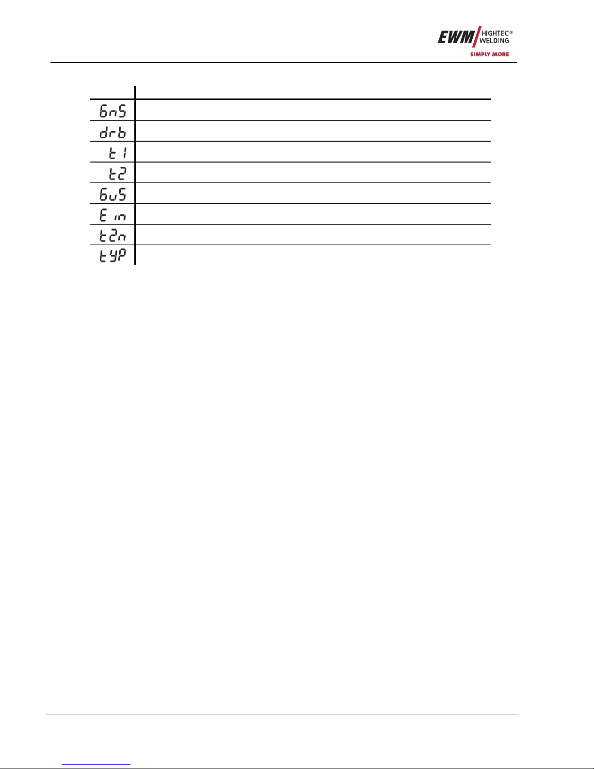
5.1.3.10 Explanation of symbols
Symbol Meaning
"GnS" - Gas post-flows
"drb" - Wire burn-back
"t1" - Spot time
"t2" - Interval time
"GvS" - Gas pre-flows
"On" - Wire creep
"tZn" - Ignition time
"tyP" - Machine type (type table, see chapter "Reset to factory settings")

Functional characteristics
MIG/MAG functional sequences / operating modes
Item No.: 099-004934-EWM01 45
5.2 MIG/MAG functional sequences / operating modes
NOTE
There are optimum pre-sets for welding parameters such as gas pre-flow and free-burn,
etc. for numerous applications (although these can also be changed if required).
5.2.1 Explanation of signs and functions
Symbol Meaning
Press torch trigger
Release torch trigger
Tap torch trigger (press briefly and release)
Shielding gas flowing
I
Welding output
Wire electrode is being conveyed
Wire creep
Wire burn-back
Gas pre-flows
Gas post-flows
Non-latched
Latched
t
Time
t1
Spot time
t2
Interval pause
tZn
Ignition time

Functional characteristics
MIG/MAG functional sequences / operating modes
46 Item No.: 099-004934-EWM01
5.2.2 Non-latched operation
Figure 5-9
Step 1
• Press and hold torch trigger.
• Shielding gas is expelled (gas pre-flows).
• Wire feed motor runs at "creep speed".
• Arc ignites after the wire electrode makes contact with the workpiece; welding current flows.
• Changeover to the pre-selected wire speed after the set ignition time (tZn).
Step 2
• Release torch trigger.
• WF motor stops.
• Arc is extinguished after the pre-selected wire burn-back time elapses.
• Gas post-flow time elapses.

Functional characteristics
MIG/MAG functional sequences / operating modes
Item No.: 099-004934-EWM01 47
5.2.3 Latched operation
Figure 5-10
Step 1
• Press and hold torch trigger.
• Shielding gas is expelled (gas pre-flows).
• Wire feed motor runs at "creep speed".
• Arc ignites when the wire electrode makes contact with the workpiece; welding cu rrent flows.
• Changeover to the pre-selected wire speed after the set ignition time (tZn).
Step 2
• Release torch trigger (no effect).
Step 3
• Press torch trigger (no effect).
Step 4
• Release torch trigger.
• WF motor stops.
• Arc is extinguished after the pre-selected wire burn-back time elapses.
• Gas post-flow time elapses.

Functional characteristics
MIG/MAG functional sequences / operating modes
48 Item No.: 099-004934-EWM01
5.2.4 Spots
Figure 5-11
1. Start
• Press and hold torch trigger.
• Shielding gas is expelled (gas pre-flows).
• Wire feed motor runs at "creep speed".
• Arc ignites after the wire electrode makes contact with the workpiece; welding current flows.
• Changeover to the pre-selected wire speed after the set ignition time (tZn).
• The WF stops after the set spot time elapses.
• Arc is extinguished after the pre-selected wire burn-back time elapses.
• Gas post-flow time elapses.
2. End
• Release torch trigger.
NOTE
When the torch trigger is released, the welding process is also interrupted even before
the spot time elapses.
With fast tacking (time between two welding process under approx. 1.5 seconds) the gas
pre-flow, the creep process and also the ignition time (tZn) are not required.

Functional characteristics
MIG/MAG functional sequences / operating modes
Item No.: 099-004934-EWM01 49
5.2.5 Interval
Figure 5-12
1. Start
• Press and hold torch trigger.
• Shielding gas is expelled (gas pre-flows).
• Wire-feed motor runs at "creep-start speed".
• Arc ignites after the wire electrode makes contact with the workpiece; welding current flows.
• Changeover to the pre-selected wire speed after the set ignition time (tZn).
• The wire feed stops after the pulse time expires.
• Arc is extinguished after the wire burn-back time elapses.
• The process is repeated after the pause time elapses.
2. End
• Release torch trigger.
• Wire feed stops.
• Arc is extinguished after the wire burn-back time elapses.
• Gas post-flow time elapses.
NOTE
When the torch trigger is released, the welding process is also interrupted even before
the spot time elapses.
With fast tacking (time between two welding process under approx. 1.5 seconds) the gas
pre-flow, the creep process and also the ignition time (tZn) are not required.
5.2.6 MIG/MAG automatic cut-out
NOTE
The welding machine ends the ignition process or the welding process with an
• Ignition fault (no welding current flows within 5 s after the start signal).
• Arc interruption (arc is intrerupted for longer than 3 s).

Commissioning
General
50 Item No.: 099-004934-EWM01
6 Commissioning
6.1 General
DANGER
Risk of injury from electric shock!
Contact with live parts, e.g. welding current sockets, is potentially fatal!
• Follow safety instructions on the opening pages of the operating instructions.
• Commissioning may only be carried out by persons who have the relevant expertise of
working with arc welding machines!
• Connection and welding leads (e.g. electrode holder, welding torch, workpiece lead,
interfaces) may only be connected when the machine is switched off!
CAUTION
Risk of burns on the welding current connection!
If the welding current connections are not locked, connections and leads heat up and can
cause burns, if touched!
• Check the welding current connections every day and lock by turning in clockwise direction, if
necessary.
CAUTION
Using protective dust caps!
Protective dust caps protect the connection sockets and ther efore the machine against
dirt and damage.
• The protective dust cap must be fitted if there is no accessory component being operated on
that connection.
• The cap must be replaced if faulty or if lost!
6.2 Area of application – proper usage
WARNING
Hazards due to improper usage!
Hazards may arise for persons, animals and material objects if the equipment is not used
correctly. No liability is accepted for any damages arising from improper usage!
• The equipment must only be used in line with proper usage and by trained or expert staff!
• Do not modify or convert the equipment improperly!
These welding machines are only suitable for GMAW welding and GMAW brazing.
CAUTION
Damage due to the use of non-genuine parts!
The manufacturer's warranty becomes void if non-genuine parts are used!
• Only use system components and options (power sources, welding torches, electrode
holders, remote controls, spare parts and replacement parts, etc.) from our range of
products!
• Only insert and lock accessory components into the relevant connection socket when the
machine is switched off.

Commissioning
Installation
Item No.: 099-004934-EWM01 51
6.3 Installation
CAUTION
Installation site!
The machine must not be operated in the open air and must only be set up and operated
on a suitable, stable and level base!
• The operator must ensure that the ground is non-slip and level, and provide sufficient
lighting for the place of work.
• Safe operation of the machine must be guaranteed at all times.
6.4 Mains connection
DANGER
Hazard caused by improper mains connection!
An improper mains connection can cause injuries or damage property!
• Only use machine with a plug socket that has a correctly fitted protective conductor.
• If a mains plug must be fitted, this may only be carried out by an electrician in accordance
with the relevant national provisions or regulations (any phase sequence for three-phase
machines)!
• Mains plug, socket and lead must be checked regularly by an electrician!
CAUTION
Operating voltage - mains voltage!
The operating voltage shown on the rating plate must be consistent with the mains
voltage, in order to avoid damage to the machine!
• For mains fuse protection, please refer to the “Technical data” chapter!
• Insert mains plug of the switched-off machine into the appropriate socket.
6.5 Machine cooling
NOTE
In this machine series, the machine and torch cooling are temperature controlled. Fans
and coolant pump are therefore only switched on if required, or during the welding
process.
When the torch trigger is pressed and held down, the fans and the pump always run. If the torch
trigger is not being pressed, the fans and pump only run when the temperature exceeds a set
limit value.
To obtain an optimal duty cycle from the power components, the following precautions should be
observed:
• Ensure that the working area is adequately ventilated.
• Do not obstruct the air inlets and outlets of the machine.
• Do not allow metal parts, dust or other objects to get into the machine.

Commissioning
Coolant
52 Item No.: 099-004934-EWM01
6.6 Coolant
CAUTION
Coolant mixtures!
Mixtures with other liquids or the use of unsuitable coolants result in material damage
and renders the manufacturer's warranty void!
• Only use the coolant described in this manual (overview of coolants).
• Do not mix different coolants.
• When changing the coolant, the entire volume of liquid must be changed.
6.6.1 List of coolants
The following coolants may be used (for item nos., please see the Accessories chapter):
Coolant Temperature range
KF 23E (Standard) -10°C to +40°C
KF 37E -20°C to +10°C
DKF 23E (for plasma machines) 0°C to +40°C
NOTE
The disposal of coolant must be carried out according to official regulations and
observing the relevant safety data sheets (German waste code number: 70104)!
• Coolant must not be disposed of together with household waste.
• Coolant must not be discharged into the sewerage system.
• Recommended cleaning agent: water, if necessary with cleaning agent added.
6.6.2 Adding coolant
The unit is supplied ex works with a minimum level of coolant.
max
min
Figure 6-1
• Fill the cooling unit with coolant up to the “max” mark (see sticker).
• Each time the unit is commissioned or re-connected, leave the unit running for a short time until all
torch or extension hoses are full of coolant.
Then check the coolant level and top up if necessary.
• The filter sieve must always be inserted in the filling pipe during filling!
NOTE
The level of coolant must never fall below the “min” mark.

Commissioning
Workpiece lead, general
Item No.: 099-004934-EWM01 53
6.7 Workpiece lead, general
CAUTION
Risk of burns due to incorrect connection of the workpiece lead!
Paint, rust and dirt on the connection restrict the power flow and may lead to stray
welding currents.
Stray welding currents may cause fires and injuries!
• Clean the connections!
• Fix the workpiece lead securely!
• Do not use structural parts of the workpiece as a return lead for the welding current!
• Take care to ensure faultless power connections!
6.8 Welding torch and workpiece line connection
Depending on the wire electrode diameter and wire electrode type, either a spiral guide or a
plastic core with the appropriate interior diameter must be inserted into the welding torch!
Recommendation:
• Use a spiral guide for welding hard wire electrodes (steel).
• Use a plastic core for welding or brazing soft wire electrodes.
NOTE
Fault with the wire guide!
On delivery, the central connector (Euro) is fitted with a capillary tube for welding torches
with spiral guides. Conversion is necessary if a welding torch with a plastic core is used!
Welding torch with plastic core:
• use with guide tube!
Welding torch with spiral guide:
• use with capillary tube!
Preparation for connecting welding torches with a plastic core:
• Push forward the capillary tube on the wire feed side in the direction of the central connector and
remove it there.
• Slide plastic core guide tube off the central connector.
• Carefully insert the central plug for the welding torch, with the still oversized plastic core, into the
central connector and screw together with crown nut.
• Use a suitable tool to cut off the plastic core just before the wire feed roller, making sure not to pinch it.
• Unfasten and remove the central plug on the welding torch.
• Cleanly remove the burr from the separated end of the plastic core!
Preparation for connecting welding torches with a spiral guide:
• Check that the capillary tube is correctly positioned in relation to the central connector!

Commissioning
Welding torch and workpiece line connection
54 Item No.: 099-004934-EWM01
Figure 6-2

Commissioning
Welding torch and workpiece line connection
Item No.: 099-004934-EWM01 55
Item Symbol Description 0
1
Central connection for welding torch (Euro)
Integrated welding current, shielding gas and torch trigger
2
Rapid-action closure coupling, red (coolant return)
3
Rapid-action closure coupling, blue (coolant supply)
4
Connection socket, workpiece lead
"Hard" choke tapping
5
Connection socket, workpiece lead
"Medium" choke tapping
6
Connection socket, workpiece lead
Choke tapping "soft"
• Insert central plug of the welding torch into the central connector and screw together with crown nut.
• Insert the cable plug of the workpiece lead into the connection socket for workpiece lead 1, 2 or 3
(depending on the application or shielding gas used) and lock by turning to the right.
• Lock connecting nipples of the cooling water tubes into the correspondin g rapid-action closure
couplings:
Return line red to rapid-action closure coupling, red (coolant return) and
supply line blue to rapid-action closure coupling, blue (coolant supply).

Commissioning
Welding torch and workpiece line connection
56 Item No.: 099-004934-EWM01
6.8.1 Intermediate tube package connection
NOTE
The following section of the document applies only to decompact welding machines.
6.8.1.1 Wire feed unit
Figure 6-3
Item Symbol Description 0
1
7-pole connection socket
Wire feed unit control lead
2
Connecting nipple G¼, shielding gas connection
3
Connector plug, welding current "+"
Welding current connection on wire feed unit
4
Rapid-action closure coupling, blue (coolant supply)
5
Rapid-action closure coupling, red (coolant return)
6
Intermediate tube package strain relief
7
Earth cable connecting nipple
Connection of green-yellow earth cable from the intermediate tube package
• Insert the end of the tube package through the strain relief of the tube package and lock by turning to
the right.
• Insert the plug on the welding current lead into the welding current connection socket "+" and lock.
• Lock connecting nipples of the cooling water tubes into the correspondin g rapid-action closure
couplings:

Commissioning
Welding torch and workpiece line connection
Item No.: 099-004934-EWM01 57
Return line red to rapid-action closure coupling, red (coolant return) and
supply line blue to rapid-action closure coupling, blue (coolant supply).
• Insert cable plug on the control lead into the 7-pole connection socket and secure with crown nut (the
plug can only be inserted into the connection socket in one position).
• Connect crown nut of the shielding gas line to the G¼“ connecting nipple.
• Screw the eyelet of the earth lead on to the connecting nipple of the earth lead.
NOTE
A pilot static tube for a gas flow of 0-16 l/min is fitted on each wire feed unit as standard.
For applications where a higher gas flow rate is required (e.g. for aluminium), a pilot
static tube of 0-25 l/min (see accessories) should be installed.
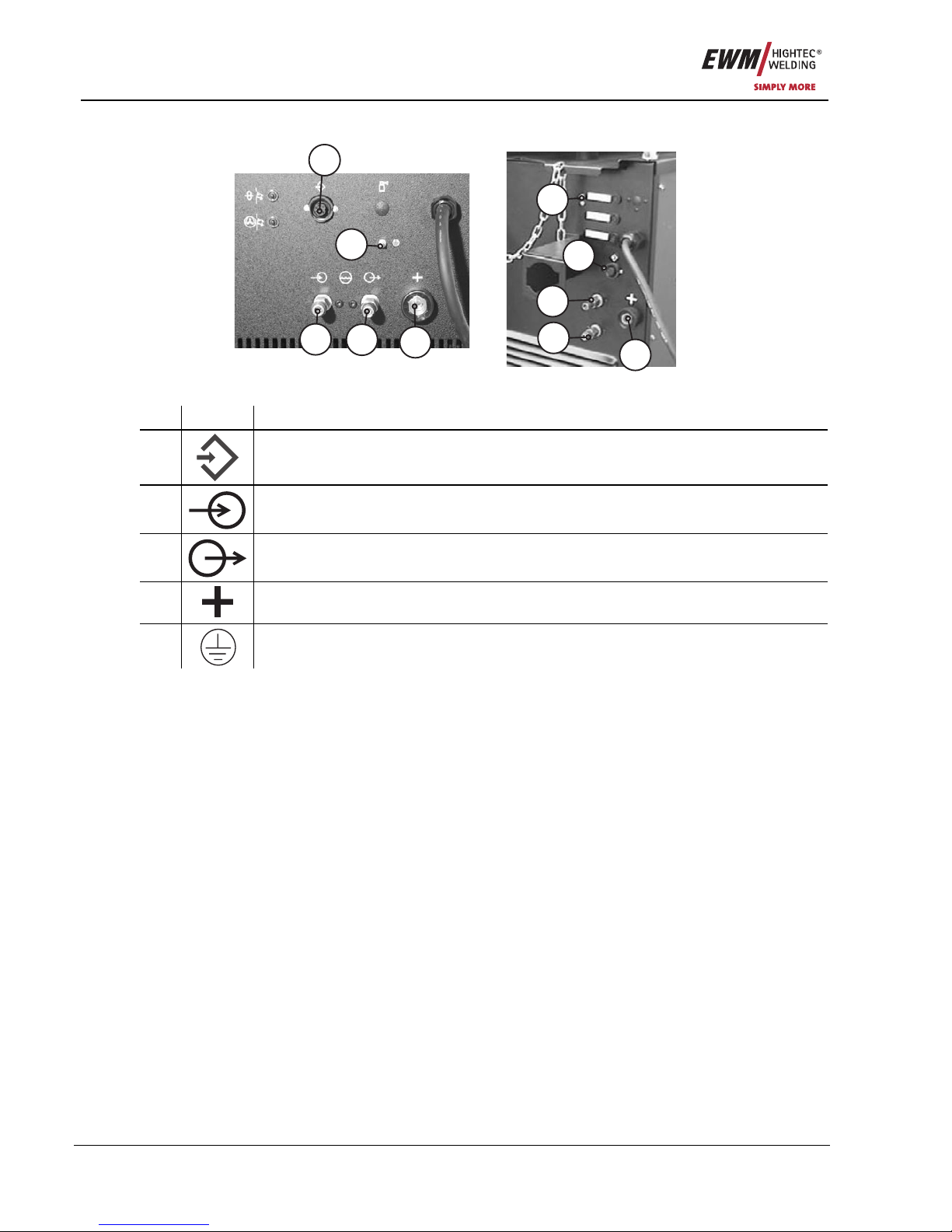
Commissioning
Welding torch and workpiece line connection
58 Item No.: 099-004934-EWM01
6.8.1.2 Welding machine
4
4
3
3
2
2
1
1
5
5
Figure 6-4
Item Symbol Description 0
1
7-pole connection socket
Wire feed unit control lead
2
Rapid-action closure coupling, red (coolant return)
3
Rapid-action closure coupling, blue (coolant supply)
4
Connector plug, welding current "+"
Welding current connection on wire feed unit
5
Earth cable connecting nipple
Connection of green-yellow earth cable from the intermediate tube package
• Insert the end of the tube package through the intermediate tube package strain relief and lock by
turning to the right.
• Insert the plug on the welding current lead into the connection socket "+" and lock.
• Lock connecting nipples of the cooling water tubes into place in the corresponding rapid-action closure
couplings:
Return, red, to rapid-action closure coupling, red (coolant return) and
Return, blue, to rapid-action closure coupling, blue (coolant supply).
• Insert the plug of the control cable into the 7-pole connection socket (digital) and secure with the
crown nut (the plug can only be inserted in one position into the connection socket).
• Connect the crown nut on the shielding gas lead to the G¼" connecting nipple, connect the shielding
gas.
• Screw the eyelet of the earth lead on to the connecting nipple of the earth lead.

Commissioning
Shielding gas supply
Item No.: 099-004934-EWM01 59
6.9 Shielding gas supply
6.9.1 Connecting the shielding gas supply
NOTE
With compact machines, the shielding gas connection is made on the machine itself;
with decompact machines, on the intermediate tube package of the wire feed (see
"Intermediate tube package connection").
Figure 6-5
Item Symbol Description 0
1
G¼” connecting nipple
Shielding gas connection on the pressure reducer
2 Safety chain
3 Cylinder bracket
4 Cylinder valve
5 Output side of the pressure reducer
6 Pressure reducer
7 Shielding gas cylinder
• Before connecting the pressure reducer to the gas cylinder, open the cylinder valve briefly to blow out
any dirt.
• Place the shielding gas cylinder into the relevant cylinder bra cket.
• Secure the shielding gas cylinder using a securing chain.
CAUTION
Faults in the shielding gas supply.
An unhindered shielding gas supply from the shielding gas cylinder to the welding torch
is a fundamental requirement for optimum welding results. In addition, a blocked
shielding gas supply may result in the welding torch being destroyed.
• Always re-fit the yellow protective cap when not using the shielding gas connection.
• All shielding gas connections must be gas tight.
• Tighten gas hose on pressure reducer to be gas tight.

Commissioning
Shielding gas supply
60 Item No.: 099-004934-EWM01
6.9.2 Gas test or "rinse tube package"
NOTE
For machines with M2.40 or M2.20 control, the gas test is carried out by pressing the
appropriate button on the control; for machines with M1.02 control, the gas test is made
on the internal operating elements (see "Machine description") of the compact welding
machine or on the internal operating elements of the wire feed.
• Slowly open the gas cylinder valve.
• Open the pressure reducer.
• Switch on the power source at the main switch.
• Initiate gas test function on the machine control.
• Set the relevant gas quantity for the application on the pressure reducer.
• Press
button. Gas flows for a maximum of 25 seconds or until button is pressed again.
6.9.3 Setting the shielding gas quantity
Welding process Recommended shielding gas quantity
MAG welding Wire diameter x 11.5 = l/min
MIG brazing Wire diameter x 11.5 = l/min
MIG welding (aluminium) Wire diameter x 13.5 = l/min (100 % argon)
TIG Gas nozzle diameter in mm corresponds to l/min gas throughput
Helium-rich gas mixtures require a higher gas volume!
The table below can be used to correct the gas volume calculated where necessary:
Shielding gas Factor
75% Ar/25% He 1.14
50% Ar/50% He 1.35
25% Ar/75% He 1.75
100% He 3.16
NOTE
Incorrect shielding gas setting!
If the shielding gas setting is too low or too high, this can introduce air to the weld pool
and may cause pores to form.
• Adjust the shielding gas quantity to suit the welding task!

Commissioning
Inserting the wire electrode
Item No.: 099-004934-EWM01 61
6.10 Inserting the wire electrode
6.10.1 Fixing the wire spool retainer (pre-tension adjustment)
NOTE
Because the spool brake also secures the wire spool retainer, the following steps are to
be carried out for every spool change and before every adjustment of the spool brake.
Figure 6-6
Item Symbol Description 0
1 Securing and braking unit
2 Allen screw
Securing the wire spool retainer and adjustment of the spool brake
3 Wire spool retainer
• Loosen the hexagonal socket screw of the securing and braking unit until the screw is free of the
thread in the wire spool retainer (do not remove it completely to prevent losing the small parts).
• Pre-tension the securing and braking unit in the wire spool retainer by screwing the hexagonal socket
screw clockwise, making at least 4 complete turns (4 x 360°).

Commissioning
Inserting the wire electrode
62 Item No.: 099-004934-EWM01
6.10.2 Spool brake setting
Figure 6-7
Item Symbol Description 0
1 Allen screw
Securing the wire spool retainer and adjustment of the spool brake
• Tighten the Allen screw (8 mm) in the clockwise direction to increase the braking effect.
NOTE
Do not jam the wire spool!
Tighten the spool brake until the wire spool no longer turns when the wire feed motor stops but
without it jamming during operation!
The fixing of the pin reel must be checked if the hexagonal socket screw is released.
See chapter “Fixing of the pin reel (adjustment of the pre-tensioning)”

Commissioning
Inserting the wire electrode
Item No.: 099-004934-EWM01 63
6.10.3 Inserting the wire spool
NOTE
Standard D300 pin reels can be used. Adapters (see accessories) are required when
using standardised basket coils (DIN 8559).
Figure 6-8
Item Symbol Description 0
1 Carrier pin
For fixing the wire spool
2 Knurled nut
For fixing the wire spool
• Loosen knurled nut from spool holder.
• Fix welding wire reel onto the spool holder so that the carrier pin locks into the spool bore.
• Fasten wire spool using knurled nut.

Commissioning
Inserting the wire electrode
64 Item No.: 099-004934-EWM01
6.10.4 Changing the wire feed rollers
NOTE
Unsatisfactory welding results due to faulty wire feeding!
Wire feed rollers must be suitable for the diameter of the wire and the material.
• Check the roller label to verify that the rollers are suitable for the wire diameter.
Turn or change if necessary!
• use V-Nut rollers with for steel wires and other hard wires,
• use U-Nut rollers for aluminium wires and other soft, alloyed wires.
• Slide new drive rollers into place so that the diameter of the wire used is visible on the drive rol ler.
• Screw the drive rollers in place with knurled screws.
Figure 6-9

Commissioning
Inserting the wire electrode
Item No.: 099-004934-EWM01 65
6.10.5 Inching the wire electrode
WARNING
Risk of injury due to inadequate wire feeding!
In the event of inadequate wire guidance, the welding wire can be ejected in an
uncontrolled way and cause serious injury.
• No wire feed with inadequate wire guidance!
• Check the wire guidance at regular intervals!
4 4
3
3
2 2
1 1
5
5
Figure 6-10
Item Symbol Description 0
1 Pressure units
2 Clamping units
3 Wire feed nipple
4 Guide tube
5 Capillary tube or plastic core with support tube, depending on the torch
equipment
• Extend and lay out the torch tube package.
• Unfasten pressure units and fold out (clamping units and counter-pressure rollers will automatically flip
upwards).
• Unwind welding wire carefully from the wire spool and insert through the wi re inlet nipple over the drive
roller grooves and the guide pipe into the capillary tube and Teflon core using guide pipe.
• Press the clamping element with the counter pressure roller back downwards and fold the wire unit s
back up again (wire electrode should be in the groove on the drive roller).
The clamping pressure must be set on the adjusting nuts of the pressure units so that
the wire electrode is conveyed but will still slip through if the wire spool jams.
The clamping pressure for the front rollers (viewed from the direction of the feed) should always
be slightly higher than that of the rear rollers.
• Press the wire inching button until the wire electrode projects out of the welding torch.

Maintenance and testing
General
66 Item No.: 099-004934-EWM01
7 Maintenance and testing
NOTE
The maintenance, cleaning and testing work described below must be conducted
correctly and on an annual basis in order qualify for claims under the EWM warranty.
7.1 General
When used in the specified environmental conditions and under normal operating condition s, this
machine is largely maintenance-free and requires a minimum of care.
There are some points, which should be observed, to guarantee fault-free operation of your welding
machine. Among these are regular cleaning and checking as descri bed below, depending on the pollution
level of the environment and the length of time the unit is in use.
NOTE
The welding machine may only be cleaned, tested and repairied by competent, capable
personsl.
A capable person is one who, because of his training, knowledge and experience, is able
to recognise the dangers that can occur while testing welding power sources as well as
possible subsequent damage and who is able to implement the required safety
procedures.
In the event of failure to comply with any one of the following tests, the machine must not
be operated again until it has been repaired and a new test has been carried out!
7.2 Cleaning
DANGER
Electric shocks!
Cleaning machines that are not disconnected from the mains can lead to serious injuries!
• Disconnect the machine completely from the mains.
• Remove the mains plug!
• Wait for 2 minutes until the capacitors have discharged.
The individual components should be handled as follows:
Power source:
Depending on the amount of dust, blow out using oil- and moisture-free compressed air.
Electronics: Do not blast electronic components or circuit boards with compressed air but clean them
with a vacuum cleaner instead.
Coolant:
Check for impurities and replace if necessary.
NOTE
Mixing coolants with other liquids or the use of other coolants voids our manufacturer's
guarantee.

Maintenance and testing
Test
Item No.: 099-004934-EWM01 67
7.3 Test
NOTE
Additional machines and add-on parts (e.g. cooling units, wire feed devices, welding
torches,...) should be tested together with the welding power source.
Some points, such as: insulation and protective conductor resistance, can be tested directly at the same
time and it can be ensured that the total leakage current from the welding power source, additional
machines and add-on parts does not exceed the limits.
For this reason, the full process of testing the welding power source is described below. If additional
machines or add-on parts are tested individually, the test points are to be adjusted if necessary (e.g. no
open circuit voltage measurement).
The test should be conducted in accordance with IEC/DIN EN 60974-4 “Arc welding equipment –
Inspection and testing during operation” in accordance with the German Ordinance of Operational Safety.
This standard is not only an international standard but is also specific to arc welding equi pment.
NOTE
The former term of repetition test has been replaced due to a change in the
corresponding standard with “Inspection and testing during operation”.
In addition to the regulations on the test given here, the relevant local laws and
regulations must also be observed.
7.3.1 Test equipment
NOTE
Due to the special conditions of inverter arc welding equipment, not all test equipment is
suitable for testing in accordance with VDE 0702 to the full extent!
EWM as a manufacturer offers all appropriately trained and authorised EWM sales partners the
appropriate test equipment and measuring devices conforming to VDE 0404-2, which eval uate the
frequency response conforming to DIN EN 61010-1 Appendix A – Measuring Circuit A1.
You as the user are tasked with ensuring that your EWM machines conform to the standard IEC/DIN EN
60974-4 and are tested with the relevant test equipment and measuring devices given above.
NOTE
The following description of the test is only a brief overview of the points to be tested.
For details about the test points or in the event of any queries, please refer to
IEC/DIN EN 60974-4.
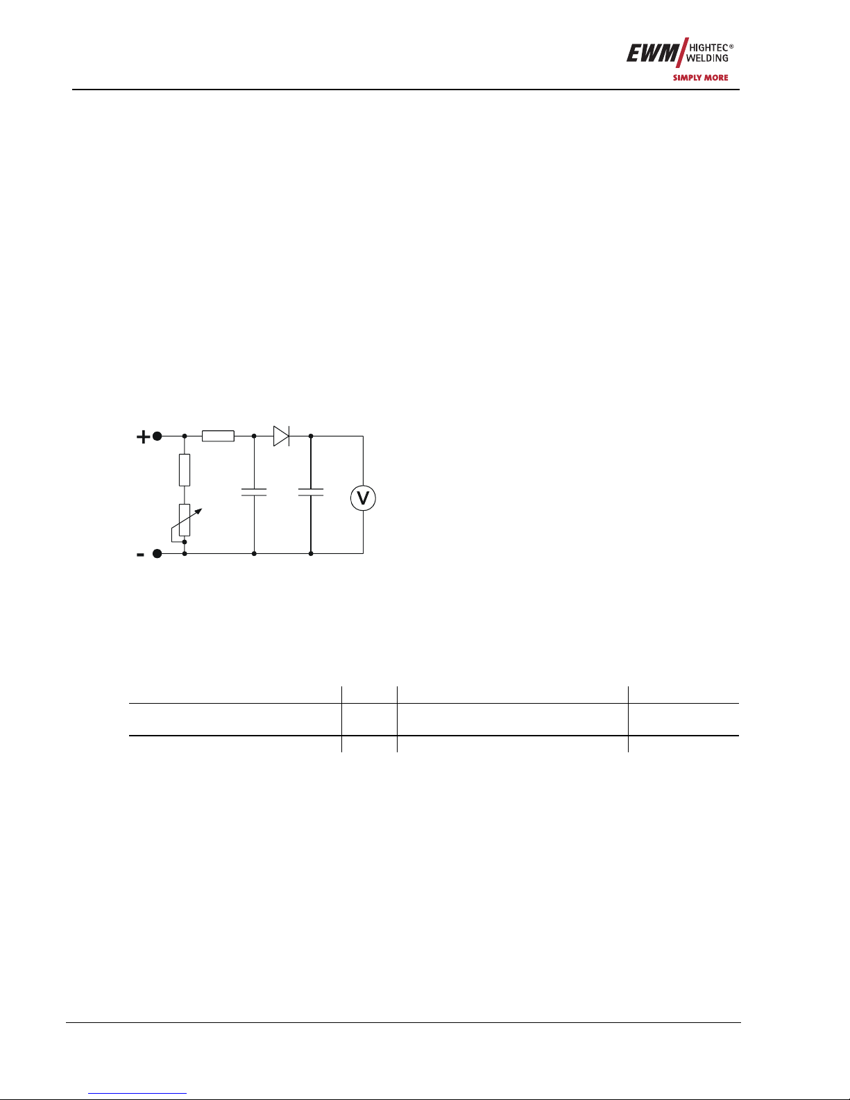
Maintenance and testing
Test
68 Item No.: 099-004934-EWM01
7.3.2 Scope of the test
a) Visual inspection
b) Electrical test: measurement of
• open circuit voltage
• insulation resistance, or alternatively
• leakage currents
• protective conductor resistance
c) Functional test
d) Documentation
7.3.3 Visual inspection
The key areas in the test are:
1. Torch/stick electrode holder, welding current return lead clamp
2. Power supply: leads including plugs and strain relief
3. Welding current circuit: leads, plugs and couplings, strain relief
4. Casing
5. Operating, message, safety and adjustment devices
6. Other, general condition
7.3.4 Measuring the open circuit voltage
6u8F
10nF
0...5k
0k2
1k0
1N 4007
Measuring circuit according to DIN EN
60974-1
Connect the measuring circuit to the welding current
sockets. The voltmeter must display mean values and
have an internal resistance ≥ 1 MΩ. In the case of step
switch controlled devices, set the maximum output voltage
(step switch). Adjust the potentiometer from 0 kΩ to 5 kΩ
during the measurement. The measured voltage should
not deviate from that specified on the rating plate by more
than +/- 5% and may be no greater than 113 V (for devices
with VRD: 35 V).
7.3.5 Measurement of insulation resistance
The mains switch must be on so that the insulation in the interior of the machine can also be checked
through to the transformer. If a mains contactor is fitted, this should be bridged or the measurement must
be carried out on both sides.
The insulation resistance must not be less than:
Mains current circuit against Welding current circuit and electroni cs
5 MΩ
Welding current circuit and
electronics
against Protective conductor circuit (PE)
2.5 MΩ
Mains current circuit against Protective conductor circuit (PE)
2.5 MΩ

Maintenance and testing
Test
Item No.: 099-004934-EWM01 69
7.3.6 Measuring the leakage current (protective conductor and contact current)
Note: Even if the leakage current measurement according to the standard is only an alternative to the
insulation resistance measurement, EWM recommends always performing both measurements,
especially following repair work. The leakage current is based for the greater part on a physical effect
other than the insulation resistance. For this reason, it may not be possible to uncover a dangerous
leakage current using the insulation resistance measurement.
These measurements cannot be performed with a normal multimeter. Even test devices for VDE 0702
(especially older devices) are generally only intended for 50/60 Hz. With inverter welding machines,
however, significantly higher frequencies occur, which can interfere with some measuring devices, and
result in others measuring the frequency incorrectly.
A test device must meet the requirements of VDE 0404-2. For the frequency response measurement,
please refer to DIN EN 61010-1 Appendix A – Measuring circuit A1.
NOTE
For these measurements, the welding machine must be switched on and supplying open
circuit voltage!
1. Protective conductor current: < 5 mA
2. Leakage current from the welding sockets separately to PE: < 10 mA
7.3.7 Measurement of protective conductor resistance
Measure between the plug earthed contact and accessible live parts, e.g. casing screws.
During the measurement, the connection lead must be moved across the entire length, especially near
the casing and plug inlet points. This should uncover any interruptions in the pro tective conductor. All
conductive parts of the casing accessible from outside should also be tested to ensure a correct PE
connection for safety class I.
The resistance must not exceed a mains connection lead 0.3Ω up to 5m in length. For longer leads, the
permissible value increases by 0.1Ω per 7.5m of lead. The maximum permissible value is 1Ω.
7.3.8 Functional test of the welding machine
Safety devices, selector switches and command units (if fitted) and the entire machine or the entire
system for arc welding, must be functioning perfectly.
1. Main switch
2. Emergency stop devices
3. Voltage reducing device
4. Gas solenoid valve
5. Message and control lamps
7.3.9 Documentation of the test
The test report must contain:
• the designation of the tested welding equipment,
• the date of the test,
• the test results,
• the signature, name of technician and the relevant institution,
• the name of the test equipment.
A label with the date of the test must be affixed to the welding machine to show that the test has been
passed.

Maintenance and testing
Repair Work
70 Item No.: 099-004934-EWM01
7.4 Repair Work
Repair and maintenance work may only be performed by qualified authorised personnel; otherwise the
right to claim under the warranty is void. In all service matters, please contact your EMW sales partner.
Returns of defective equipment subject to warranty may only be made through your EWM sales partner.
In the event of problems or queries, please contact the EWM Service Department directly (+49 (0) 2680
181 0). Use only genuine spare parts and replacement parts when replacing. When placing an order,
please quote the type designation and item number, as well as the type, serial number and item number
of the relevant equipment.
We hereby confirm that the servicing and maintenance instructions given above and the test described above have
been completed correctly.
Date/Stamp/Signature of EWM sales partner
Date/Stamp/Signature of EWM sales partner
Date of next maintenance work and test
Date of next maintenance work and test
Date/Stamp/Signature of EWM sales partner
Date/Stamp/Signature of EWM sales partner
Date of next maintenance work and test
Date of next maintenance work and test
Date/Stamp/Signature of EWM sales partner
Date/Stamp/Signature of EWM sales partner
Date of next maintenance work and test
Date of next maintenance work and test

Maintenance and testing
Disposing of equipment
Item No.: 099-004934-EWM01 71
7.5 Disposing of equipment
NOTE
Disposal!
In Germany, waste equipment from private households can be disposed of free of charge
at local community collection points. Your local administration point can provide
information on the options available. EWM participates in an approved waste disposal
and recycling system and is registered in the Used Electrical Equipment Register (EAR)
under number WEEE DE 57686922.
• This equipment must be disposed of in accordance with official regulations.
7.5.1 Manufacturer's declaration to the end user
• According to European provisions (guideline 2002/96/EG of the European Parliament and the Council
of January, 27th 2003), used electric and electronic equipment may no longer be placed in u nsorted
municipal waste. It must be collected separately. The symbol depicting a waste container on wheels
indicates that the equipment must be collected separately.
This machine is to be placed for disposal or recycling in the waste separation system s provided for this
purpose.
• According to German law (law governing the distribution, taking ba ck and environmentally correct
disposal of electric and electronic equipment (ElektroG) from 16.03.2005), used machines are to be
placed in a collection system separate from unsorted municipal waste. The publi c waste management
utilities (communities) have created collection points at which used equipment from private households
can be disposed of free of charge.
• Information about giving back used equipment or about collections can be obtained from the
respective municipal administration office.
• EWM participates in an approved waste disposal and recycling system and is registered in the Used
Electrical Equipment Register (EAR) under number WEEE DE 57686922.
• In addition to this, returns are also possible throughout Europe via EWM sales partners.
7.6 Meeting the requirements of RoHS
We, EWM HIGHTEC Welding GmbH Mündersbach, hereby co nfirm that all products supplied by us which
are affected by the RoHS Directive, meet the requirements of the RoHS (Directive 2002/95/EC).

Warranty
General Validity
72 Item No.: 099-004934-EWM01
8 Warranty
8.1 General Validity
3-year warranty
on all new EWM machines*:
• Power sources
• Wire feeds
• Cooling units
• Trolleys
* If these are operated with genuine EWM accessories (such as intermediate tube package, remote
control, remote control extension cable, coolant, etc.).
1-year warranty on:
• Used EWM machines
• Automation and mechanisation components
• Remote control
• Inverters
• Intermediate tube packages
6-month warranty on:
• Spare parts supplied separately (such as circuit boards, ignition units)
Manufacturer/supplier warranty on:
• All additional parts used by EWM, but manufactured by other companies (e.g. motors, pumps, fans,
torches, etc.)
Non-reproducible software errors and parts subject to mechanical ageing are excluded from the warranty
(e.g. wire feed unit, wire feed rollers, replacement and spare wire feed parts, wheels, solenoid valves,
workpiece leads, electrode holders, connection tubes, replacement torches and spare torch parts, mains
and control leads, etc.).
These terms shall apply without affecting the customer’s legal righ ts to a warranty and subject to our
General Terms and Conditions of Business and our terms on the warranty de claration. Agreements to the
contrary must be confirmed by EWM in writing.
Our General Terms and Conditions of Business are available for access anytim e online at
www.ewm.de
.

Warranty
Warranty Declaration
Item No.: 099-004934-EWM01 73
8.2 Warranty Declaration
Your 3-year warranty
Regardless of statutory warranty rights and based on our General Terms and Conditions, EWM
HIGHTEC WELDING GmbH provides a 3-year warranty for its welding products starting on the date of
purchase. Different warranty periods apply to accessories and spare parts; please see the “General
Validity” section for these periods. Parts subject to wear are naturally exempt from the warranty.
EWM guarantees the error-free condition of the products in terms of materials and processing. If the
product proves to be defective in terms of materials or processing within the warranty period, you are
entitled to free repair or to replacement with an appropriate product, at our discretion. On receipt by EWM
the returned product becomes the property of EWM.
Condition
The prerequisite for receiving the full 3-year warranty is simply to operate the products in accordance with
the EWM operating instructions observing the relevant legal recommend ations and guidelines and having
annual maintenance work and testing conducted by an EWM sales partner (see “Maintenance and
testing” chapter). This is because only machines that are maintained regularly function correctly in the
long term.
Making a claim
When making a claim under the warranty, please contact your EWM authorised sales pa rtner only.
Warranty exclusions
No warranty claims can be accepted if the EWM products in question are not operated using genuine
EWM accessories (such as intermediate tube package, remote control, remote control extension cable,
coolant, etc.). The warranty does not apply to products that are damaged due to accidents, misuse,
improper operation, incorrect installation, use of force, disregard of the specifications and operating
instructions, inadequate maintenance (see chapter “Maintenance and testing”), exte rior influences, acts of
God or personal misfortunes. Furthermore, it is not valid in the case of improper changes, repairs or
modifications. In addition, a claim for warranty does not exist in the case of partially or completely
dismantled products and interventions by persons who are not authori sed by EWM, as well as in the case
of normal wear.
Limitation
All claims regarding fulfilment or non-fulfilment on the part of EWM from this declaration in connection
with this product are limited as follows to the replacement of the actual damages. EWM’s liability
stemming from this declaration in connection with this product is fundamentally limited to the amount that
the purchaser originally paid for the original purchase. This limitation does not apply to personal injuries
or damage to property caused by negligent behaviour on the part of EWM. In no way will EWM be
responsible for lost profits, indirect or subsequent damage. EWM is not liable for damages based on the
claims of third parties.
Place of jurisdiction
If the person making the claim is a business person, the sole place of jurisdiction for all disputes resulting
directly or indirectly from the contractual relationship shall be the headquarters or the branch office of the
supplier, at the discretion of the supplier. The purchaser gains ownership of the products supplied as
replacements within the framework of the warranty adjustment at the time of the exchange.

Operating problems, causes and remedies
Customer checklist
74 Item No.: 099-004934-EWM01
9 Operating problems, causes and remedies
9.1 Customer checklist
Error Possible cause Remedy
Spatter has blocked the
contact nozzle
Clean nozzle, spray on separating agent
Feed roller is slipping Check contact pressure roller. Check for
wear and tear and replace if necessary
Wire feed motor is not turning
over
Check automatic cut-out on the wire feed
motor
Wire bent Unfasten contact nozzle, cut off wire after
bent section
Wire coil brake too strong Set coil brake correctly
No wire feed
Torch defective Replace
Core or nozzle blocked Clean, replace if necessary Loop in wire
Tube package bent too much Stretch out tube package
Wire feed coils blocked or
damaged
Clean, replace if necessary
Wire coil brake too strong Set coil brake correctly
Wire feed irregular
Contact nozzle too small Check, replace if necessary
Incorrect shielding gas setting Correct: Rule of thumb "Wire diameter *10 =
flow in l/min"
Gas cylinder empty Change
Electrode is projecting too far
forwards
Move torch closer to weld seam
Air current Shield welding area
Poor wire quality Use high quality wire, store in a dry and
clean location.
Very dirty workpiece Clean workpiece first
Local overheating of the
workpiece
Include occasional pauses in welding to
allow the workpiece to cool down.
Weld seam porous
Gas line is drawing in air Check seal tightness on lines, seal / replace
if necessary.
No mains voltage Check the mains fuses, replace as
necessary
Machine will not switch
on
Power source faulty Contact service
Blow effect Connect workpiece line more appropriately Strong spatter
No gas Set gas quantity to match the application
Workpiece line has no or poor
contact
Check connection No welding current
Power source overheating Allow machine to cool down
Wire feed or gas valve
faulty
Electronic control Check line connections, replace electronics
if necessary. Contact service
9.2 Resetting the control (Reset all)
NOTE
M2.40 control
The first action should always be to check and if necessary correct the machine type setting.

Operating problems, causes and remedies
Check the machine type setting
Item No.: 099-004934-EWM01 75
NOTE
All user settings will be overwritten with factory settings and must therefore be checked
afterwards, or set up again!
After resetting the machine control to the factory settings, it is essential that the machine
type used is checked and reset if necessary.
Operating
element
Action Result
1 x
Switch off the welding machine.
+
Press and hold both buttons.
1 x
Switch on the welding machine, "rES" is shown briefly on the display.
9.3 Check the machine type setting
NOTE
When first switching on after resetting to the factory settings, the machine type is
displayed under the designation "tyP".
If an incorrect machine type is shown, it must be reset.
„tyP 00“ SATURN 251
„tyP 01“ SATURN 301
„tyP 02“ SATURN 351
„tyP d02“ WEGA 351, SATURN 351 DG
„tyP d03” WEGA 401,451
„tyP d04” WEGA 501,601
9.4 Setting the machine type
Operating
element
Action Result
1 x
Switch off the welding machine.
+
+
Press and hold both buttons.
1 x
Switch on the welding machine, "Anl" is shown on the display.
Whilst "Anl" is being displayed, set the machine type:
0 - SATURN 251 2 - SATURN 351
1 - SATURN 301 3 - WEGA (all)

Accessories, options
General accessories
76 Item No.: 099-004934-EWM01
10 Accessories, options
10.1 General accessories
Type Designation Item no.
KF 23E-10 Coolant (-10 °C), 9.3 l 094-000530-00000
KF 37E-10 Coolant (-20 °C), 9.3 l 094-006256-00000
TYP 1 Frost protection tester 094-01 449 9-00000
AK300 Adapter for K300 basket coil 094-001803-00001
DM1 32L/MIN Manometer pressure reducer 094-000009-00000
G1 2M G1/4 R 2M Gas hose 094-000010-00001
GS16L G1/4" SW 17 Pilot static tube 094-000914-00000
GS25L G1/4" SW 17 Pilot static tube 094-001100-00000
5POLE/CEE/32A/M Machine plug 094-000207-00000
WEGA DRIVE 41 M1.02 WE Wire feed unit, water, Euro/central connector 090-004962-00102
WEGA DRIVE 41 M2.20 WE Wire feed unit, water, Euro/central connector 090-004963-00102
WEGA DRIVE 41 M2.40 WE Wire feed unit, water, Euro/central connector 090-004964-00102
WEGA DRIVE 41L M1.01 WE Wire feed unit, water, Euro/central connector 090-004965-00102
WEGA DRIVE 41L M2.20 WE Wire feed unit, water, Euro/central connector 090-004966-00102
WEGA DRIVE 41L M2.40 WE Wire feed unit, water, Euro/central connector 090-004967-00102
WEGA 351 KG
MT300G 3M EZA MIG welding torch, gas cooled 094-013428-00000
WK50QMM 4M KL Workpiece cable, clamp 092-000003-00000
WEGA 351 DG
MT300G 3M EZA MIG welding torch, gas cooled 094-013428-00000
WK50QMM 4M KL Workpiece cable, clamp 092-000003-00000
50QMM MIG G 1M Intermediate hose package, gas 094-000579-00000
50QMM MIG G 5M Intermediate hose package, gas 094-000579-00001
50QMM MIG G 10M Intermediate hose package, gas 094-000579-00002
WEGA 351 KW
MT350W 3M EZA MIG welding torch, water cooled 094-013642-00000
WK50QMM 4M KL Workpiece cable, clamp 092-000003-00000
WEGA 351 DW
MT350W 3M EZA MIG welding torch, water cooled 094-013642-00000
WK50QMM 4M KL Workpiece cable, clamp 092-000003-00000
ZWIPA 50QMM MIG W 1M Intermediate hose package, water
094-000405-00000
ZWIPA 50QMM MIG W 5M Intermediate hose package, water 094-000405-00001
ZWIPA 50QMM MIG W 10M Intermediate hose package, water 094-000405-00002
WEGA 401, 451 KG
MIG SB 400G G 3M MIG welding torch, gas 094-003413-00000
WK70QMM 4M Z Workpiece cable, grip 092-000013-00000
WEGA 401 DG
MIG SB 400G G 3M MIG welding torch, gas 094-003413-00000
WK70QMM 4M Z Workpiece cable, grip 092-000013-00000
70QMM MIG G 1M Intermediate hose package, gas 094-000580-00000
70QMM MIG G 5M Intermediate hose package, gas 094-000580-00001
70QMM MIG G 10M Intermediate hose package, gas 094-000580-00002

Accessories, options
Options
Item No.: 099-004934-EWM01 77
WEGA 401, 451 KW
MT500W 3M EZA MIG welding torch, water cooled 094-013429-00000
WK70QMM 4M Z Workpiece cable, grip 092-000013-00000
WEGA 401, 451, 501 DW
MT500W 3M EZA MIG welding torch, water cooled 094-013429-00000
WK70QMM 4M Z Workpiece cable, grip 092-000013-00000
ZWIPA 70QMM MIG W 1M Intermediate hose package, water 094-000406-00000
ZWIPA 70QMM MIG W 5M Intermediate hose package, water 094-000406-00001
ZWIPA 70QMM MIG W 10M Intermediate hose package, water 094-000406-00002
WEGA 601 DW
MT500W 3M EZA MIG welding torch, water cooled 094-013429-00000
WK95QMM 4M Z Workpiece lead, tongs 092-000171-00000
ZWIPA 95QMM MIG W 1M Intermediate hose package, water 094-000407-00000
ZWIPA 95QMM MIG W 5M Intermediate hose package, water 094-000407-00001
ZWIPA 95QMM MIG W 10M Intermediate hose package, water 094-000407-00002
10.2 Options
Type Designation Item no.
ON RMSDDV1 Optional wheel assembly retrofit kit Drive4/4S 090-008035-00000
ON RMSDV2 Optional wheel assembly retrofit kit for DRIVE4L 090-008151-00000
ON WIRE CREEP POTI
M1.02
Retrofit option, wire creep rotary dial 092-001102-00000
ON FSB WHEELS W/T/P Retrofit option for locking brake for machine wheels 092-002110-00000
WEGA 351, 401, 451
ON FILTER W Retrofit option contamination filter for air inlet 092-002091-00000
ON HOSE/FR MOUNT Optional holder for tubes and remote control for
machines without star handle
092-002116-00000
ON HOSE/FR MOUNT DK Optional holder for tubes and remote control for
machines with star handle
092-002117-00000
ON TOOL BOX Retrofit option tool box 092-002138-00000
ON HOLDER GAS BOTTLE
<50L
Retrofit option holding plate for gas bottle <50 L 092-002151-00000

Accessories, options
Wire feed rollers
78 Item No.: 099-004934-EWM01
10.3 Wire feed rollers
1.1.1 Wire feed rollers for steel wire
Type Designation Item no.
FE 2DR4R 0,6+0,8 Drive rollers, 37 mm, steel 092-000839-00000
FE 2DR4R 0,8+1,0 Drive rollers, 37 mm, steel 092-000840-00000
FE 2DR4R 0,9+1,2 Drive rollers, 37 mm, steel 092-000841-00000
FE 2DR4R 1,0+1,2 Drive rollers, 37 mm, steel 092-000842-00000
FE 2DR4R 1,2+1,6 Drive rollers, 37 mm, steel 092-000843-00000
FE/AL 2GR4R Counterpressure rollers, smooth, 37mm 092-000844-00000
10.3.1 Wire feed rollers for aluminium wire
Type Designation Item no.
AL 4ZR4R 0,8+1,0 Twin rollers, 37 mm, for aluminium 092-000869-00000
AL 4ZR4R 1,0+1,2 Twin rollers, 37 mm, for aluminium 092-000848-00000
AL 4ZR4R 1,2+1,6 Twin rollers, 37 mm, for aluminium 092-000849-00000
AL 4ZR4R 2,4+3,2 Twin rollers, 37 mm, for aluminium 092-000870-00000
10.3.2 Wire feed rollers for cored wire
Type Designation Item no.
ROE 2DR4R 0,8/0,9+0,8/0,9 Drive rollers, 37 mm, cored wire 092-000834-00000
ROE 2DR4R 1,0/1,2+1,4/1,6 Drive rollers, 37 mm, cored wire 092-000835-00000
ROE 2DR4R 1,4/1,6+2,0/2,4 Drive rollers, 37 mm, cored wire 092-000836-00000
ROE 2DR4R 2,8+3,2 Drive rollers, 37 mm, cored wire 092-000837-00000
ROE 2GR4R Counterpressure rollers, knurled, 37mm 092-000838-00000
10.3.3 Conversion sets
Type Designation Item no.
URUE VERZ>UNVERZ FE/AL
4R
Conversion kit, 37mm, 4-roller drive on non-toothed
rollers (steel/aluminium)
092-000845-00000
URUE AL 4ZR4R 0,8+1,0 Conversion kit, 37mm, 4-roller drive for aluminium 092-000867-00000
URUE AL 4ZR4R 1,0+1,2 Conversion kit, 37mm, 4-roller drive for aluminium 092-000846-00000
URUE AL 4ZR4R 1,2+1,6 Conversion kit, 37mm, 4-roller drive for aluminium 092-000847-00000
URUE AL 4ZR4R 2,4+3,2 Conversion kit, 37mm, 4-roller drive for aluminium 092-000868-00000
URUE ROE 2DR4R
0,8/0,9+0,8/0,9
Conversion kit, 37mm, 4-roller drive for cored wire 092-000830-00000
URUE ROE 2DR4R
1,0/1,2+1,4/1,6
Conversion kit, 37mm, 4-roller drive for cored wire 092-000831-00000
URUE ROE 2DR4R
1,4/1,6+2,0/2,4
Conversion kit, 37mm, 4-roller drive for cored wire 092-000832-00000
URUE ROE 2DR4R 2,8+3,2 Conversion kit, 37mm, 4-roller drive for cored wire 092-000833-00000

Circuit diagrams
WEGA KG, KW (M1.02)
Item No.: 099-004934-EWM01 79
11 Circuit diagrams
NOTE
Original format circuit diagrams are located inside the machine.
11.1 WEGA KG, KW (M1.02)
L1
L1
Xx-L2L2L3L3
PE
PE
S1-
U V
L2L1
K1-1
K1-3
K1-5
1534
6
2
K1-
L1
L2
L3
S2- S3-
T1-
2u2F
2u2F
V1-
~
~
~
-
+
123
4
Res.
C02
Mix hart
Argon
Mix
3
2
1
Drosselanschlüsse
432
1
Res
50C°
Gleichrichter
F6-
3 4
90C°
Gleichrichter
F7-
1 2
BT
Zentralanschluß
X6-
1
2
2x2n2F
PE
2x2n2F
1?T2?T3
-
W
PEPE
4x2n2F
1
PE-
PE
K1-1
K1-3
4
400V
1?T2?T1?T2
?T
1
230VAC
S4-
?T
3
4
S5-
?T
3
4
1
Schütz
2
Schütz
3
Temp. Trafo
4
Temp. Trafo
5
Temp. Gleichrichter
6
Temp. Gleichrichter
7
Temp. Trafo
8
Temp. Trafo
9
Temp. Gleichrichter
10
Temp. Gleichrichter
11
Druckwächter
K
A
H1-
LED gelb
+
V1-
-
V1-
X5-
1 2
?T?T?T
?T
1
0VAC
2
Schütz
3
US-
4
42VAC
4
Gas
5
Einfädeln6Einfädeln
7
42VAC
9
SäWa
8
1
BRT2BRT
X1/1
X1/2
X1/3
X1/4
X1/5
X1/6
X5/1
X5/2
X5/3
X5/4
X5/5
X5/6
X5/7
X5/8
X5/9
X5/10
X5/12
X5/11
X5
X2/1
X2/2
X2/3
X2/4
X3/2
X3/1
X4/2
X4/1
X6/1
X6/2
X6/3
X6/4
X2
X3
X6
X4
42VAC1
Gas
Schütz
0VAC
X1
42VAC
M 1 0 2
A2-
1
Druckwächter
1
0VAC
3
Gas
1
2
PE
Y1-
Gas
1
PE2-
PE
7
42VAC
1
+12V2T-Gasnach4T_Rückb
DRB
GNS
132
1E2S3
A
P1-
Einschleichen
2
1
3
-
M
+ -
Drahtvorschub
M6-
1?T2
?T
?C°
?T?T
?T?T
?T?T
?T?T
?C°
Trafo Trafo
F4- F5-
1 2 3 4
X2-
Temp
105°C
864
2
161415
11
9
T2-
10
20V3
230V
1
2
4A
F2-
Rückseite
1
2
4A
F3-
1
2
Gasgekühlt
4?T3
Wassergekühlt
3
4
Druckwächter
F8-
7
0VAC100VAC
13
230VAC14230VAC
16
0VAC170VAC
18
230VAC
1?T2
?T
schwarzrot
2-Rollen Antrieb
schwarz
4-Rollen Antrieb
rot
Anschluß 2Rollen/4Rollenantrieb
Stecker X4 X4/2X4/1
1
2
2.5A
F1-
Frontseite
123
4
X3-
bl
sw
gnge
?T
?T?T?T
?T
1
42VAC
3
0VAC
2
H1-A
6
0VAC
1
Schütz3Schütz4Schütz
K1-
A1 A2
5?T6?T7
H1-A
8?T10
?T
8
?T
10
?T
3
PE
Pumpe
1~
M
M5-
Gastest
Einfädeln
123
4
X1-
?T?T?T
?T
?T?T?T
?T
1~ 1~1~
M1-M4
Lüfter
1~ 1~1~
nur bei 500-600A Anlagen!
M7-M8
Lüfter
Optional:
V M 2 / 1
A3-
1413
14K1-K1-13
15
42V
14
0V
K
A
LED grün
H2-
Frontseite
K1-
14
K1-
13
14K1-1K1-113
5857
X5/1
X5/2
X5/3
X5/4
X5/5
X5/6X5X5/7
X5/8
X5/9
X5/10
X5/11
X5/12
1
K1
X1
X1/1
X1/2
X1/3
X1/4
X1/5
X1/6
X1/7
X1/8
X1/9
X1/10
X1/11
X1/12
X2
X2/1
X2/2
X2/3
X2/4
X2/5
X2/6
24
0R
K4K2
JP10
K3
+30V
1
4
24
5
3
1
2
JP9
X3/10
X3/11
X3/12
X3/1
X3/2
X3/3
X3/4
X3/5
X3/6
X3/7
X3/8
X3/9
X3
X4/10
X4/11
X4/12
X4/1
X4/2
X4/3
X4/4
X4/5
X4/6
X4/7
X4/8
X4/9
X4
A1-
W K - 5
Zeitstufe
JP11
8
Datum: Name:
gezeichnet:
geprüft:
Freigabe:
14.02.2007
21.06.2007
06.07.2006
NIEDENTHAL
NIEDENTHAL
NIEDENTHAL
12.11.2007 NIEDENTHAL
Blatt: /1
This drawing is protected by copyright.
It may not be reproduced or utilised in any way
or communicated or forwarded to third parties
without our express permission!
1
WEGA 351-601 MIG M1.02
4243-03
Zeichnungsnummer:
MIG-GERAET, FAHR. GAS./WASS.
Änderung-
Änderung-
Änderung-
Änderung-
010203
Figure 11-1

Circuit diagrams
WEGA KG, KW (M2.20/M2.40)
80 Item No.: 099-004934-EWM01
11.2 WEGA KG, KW (M2.20/M2.40)
BT
Zentralanschluß
X6-
1
2
4x2n2F
1?T2?T3
-
W
PEPE
4x2n2F
X4-
+
-
R1-
+
-
1 2
2
BRT
1
BRT
3
US-
4
42VAC
2
Schütz
1
0VAC
5
20VAC
6
20VAC
K
A
H1-
LED gelb
PE
+
V1-
123
4
Res.
C02
Mix hart
Argon
Mix
3
2
1
Drosselanschlüsse
432
1
Res
S1-
U V
L2L1
50C°
Gleichrichter
F6-
3 4
90C°
Gleichrichter
F7-
1 2
4
400V
3
230V
1?T2
?T
1
230VAC
7
0VAC100VAC
14
230VAC
1
Schütz
2
Schütz
3
Temp. Trafo
4
Temp. Trafo
5
Temp.Gleichrichter
6
Temp. Gleichrichter
7
Temp.Trafo
8
Temp. Trafo
9
Temp. Gleichrichter
10
Temp.Gleichrichter
11
Druckwächter
4
V1+
8
20V90V
L1
L2
L3
T1-
2u2F
2u2F
V1-
~
~
~
-
+
?T?T
?T?T
?T?T
?T?T
Temp.-Trafo Temp.-Trafo
F4- F5-
1 2 3 4
X2-
4?T3
Wassergekühlt
1
Druckwächter
7
42VAC
-
V1-
PE
PE3-
1
Motor +/-2Motor -/+
M 2 2 0 / 1
A2-
X2/9
X2/8
X2/7
X2/6
X2/5
X2/4
X2/3
X2/2
X2/1
X2/16
X2/15
X2/14
X2/13
X2/12
X2/11
X2/10
X2
X1/2
X1/3
X1/4
X1/1
X1/5
X1/6
X1
X3/2
X3/1
X3
XPE
+15V
X1/16
X1/15
X1/14
X1/13
X1/12
X1/11
X1/10
X1/9
X1/8
X1/7
X1/6
X1/5
X1/4
X1/3
X1/2
X1/1
CS2
CS1
RD1
WR1
+5V
CLK1
0V1
Drehg. A
Drehg. A
(nb)
10V Uref
/OE
NC
NC
X1
0VANG
X5/4
X5/3
X5/2
X5/1
X5/6
X5/5
X5/8
X5/7
X5
+15V
X6/16
X6/15
X6/14
X6/13
X6/12
X6/11
X6/10
X6/9
X6/8
X6/7
X6/6
X6/5
X6/4
X6/3
X6/2
X6/1
CS2
CS1
RD1
WR1
+5V
CLK1
0V1
Drehg. A
Drehg. A
(nb)
10V Uref
/OE
NC
NC
X6
0VANG
X4/2
X4/1
X10/4
X10/3
X10/2
X10/1
X4
X10
X8/2
X8/1
X8
M 2 2 0 / 2
A3-
1
Gas2Gas4IGR05Iist+6Iist-8IGR0
123456789
101112
A2-X5
GasNCGas
IGR0NCNCNCIist+
Iist-
IGR0NCNC
1
2
PE
Y1-
Gas
1
PE2-
PE
S2- S3-
Temp
105°C
864
2
161415
11
9
T2-
10
2
0V
1
2
4A
F2-
Rückseite
1?T2
?T
1
2
4A
F3-
1
2
Gasgekühlt
M
Drahtvorschub
M6-
rt sw
schwarzrot2-Rollen Antrieb
schwarz4-Rollen Antrieb rot
Anschluß 2Rollen/4Rollenantrieb
Stecker X4 X4/2X4/1
1
2
2.5A
F1-
1?T2
?T
Frontseite
1
Schütz
123
4
X3-
bl
sw
gnge
?T
?T?T?T
?T
Pumpe
1~
M
M5-
3
PE
18
230VAC
16
0VAC
13
230VAC
6
0VAC
1
42VAC
2
H1-A
6
0VAC
5
0VAC
3
4
Druckwächter
F8-
2
V1-
8
10
K1-
A1
A2
1
Schütz4Schütz7H1-K
8
10
123
4
X1-
?T?T?T
?T
?T?T?T
?T
1~ 1~1~
M1-M4
Lüfter
nur bei 500-600A Anlagen!
M7-M8
Lüfter
1~ 1~1~
L1
L1
Xx-
L2L2L3
L3
PE
PE
K1-1
K1-3
K1-5
1534
6
2
1413
K1-
14K1-
1PE-
PE
K1-1
K1-3
A4-
V M 2 / 1
K1-1
14
K1-1
13
14
K1-2
K1-213
5857
15
42V
14
0V
K
A
LED grün
H2-
Frontseite
X5/1
X5/2
X5/3
X5/4
X5/5
X5/6X5X5/7
X5/8
X5/9
X5/10
X5/11
X5/12
1
K1
X1
X1/1
X1/2
X1/3
X1/4
X1/5
X1/6
X1/7
X1/8
X1/9
X1/10
X1/11
X1/12
X2
X2/1
X2/2
X2/3
X2/4
X2/5
X2/6
24
0R
K4K2
JP10
K3
+30V
1
4
24
5
3
1
2
JP9
X3/10
X3/11
X3/12
X3/1
X3/2
X3/3
X3/4
X3/5
X3/6
X3/7
X3/8
X3/9
X3
X4/10
X4/11
X4/12
X4/1
X4/2
X4/3
X4/4
X4/5
X4/6
X4/7
X4/8
X4/9
X4
A1-
W K - 5
Zeitstufe
JP11
8
Datum: Name:
gezeichnet:
geprüft:
Freigabe:
14.02.2007
12.11.2007
15.11.2006
NIEDENTHAL
NIEDENTHAL
NIEDENTHAL
Blatt: /1
This drawing is protected by copyright.
It may not be reproduced or utilised in any way
or communicated or forwarded to third parties
without our express permission!
1
WEGA 351-651 M2.40 K
4242-02
Zeichnungsnummer:
MIG-GERAET, FAHR. GAS./WASS.
Änderung-
Änderung-
Änderung-
Änderung-
01
02
Figure 11-2

Circuit diagrams
WEGA DW, DG
Item No.: 099-004934-EWM01 81
11.3 WEGA DW, DG
L1
L2
L3
S2- S3-
T1-
2u2F
2u2F
V1-
~
~
~
-
+
123
4
Res.
C02
Mix hart
Argon
Mix
3
2
1
Drosselanschlüsse
432
1
Res
50C°
Gleichrichter
F6-
3 4
90C°
Gleichrichter
F7-
1 2
4
400V
3
230V
2?T1?T2
?T
1?T2
?T
1
Schütz
2
Schütz
3
Temp. Trafo
4
Temp. Trafo
5
Temp. Gleichrichter
6
Temp. Gleichrichter
7
Temp. Trafo
8
Temp. Trafo
9
Temp. Gleichrichter
10
Temp. Gleichrichter
11
Druckwächter
4
V1+
+
V1-
-
V1-
2?T3
-
W
PEPE
4x2n2F
1234567
42VAC
Schütz
US-
20VAC
20VAC
0VAC
PE
X5-
1
PE2-
T?
K
A
H1-
LED gelb
8
20V90V
1
?T
+
7
42VAC
1
Druckwächter
?C°
?T?T
?T?T
?T?T
?T?T
?C°
Temp.Trafo Temp.Trafo
F4- F5-
1 2 3 4
X2-
3
4
Druckwächter
F8-
3?T4
?T
2
0V
Wassergekühlt
X6-
1
230VAC
7
0VAC100VAC
13
230VAC14230VAC
16
0VAC170VAC
18
230VAC
Pumpe
1~
M
M5-
123
4
X3-
bl
sw
gnge
?T
?T?T?T
?T
1
2
Gasgekühlt
3
PE
1
42VAC
2
H1-A
6
V1-
5
0VAC
5
0VAC
K1-
A1 A2
3
Schütz4Schütz1Schütz ein8H1-K
8
?T
10
?T
8?T10
?T
123
4
X1-
?T?T?T
?T
?T?T?T
?T
1~ 1~1~
M1-M4
Lüfter
1~ 1~1~
nur bei 500-600A Anlagen!
M7-M8
Lüfter
15
42V
14
0V
K
A
LED grün
H2-
L1
L1
Xx-1
L2L2L3
L3
PE
PE
S1-
U V
L2L1
K1-11
K1-13
K1-15
1534
6
2
K1-
1
PE-1
PE
K1-11
K1-13
V M 2 / 1
A3-
1413
14K1-1K1-113
K1-1
14
K1-1
13
14K1-2K1-213
5857
Temp
105°C
864
2
161415
11
9
T2-
10
Frontseite
1
2
4A
F2-
1
?T
Rückseite
1
2
2.5A
F1-
Frontseite
1
2
4A
F3-
X5/1
X5/2
X5/3
X5/4
X5/5
X5/6X5X5/7
X5/8
X5/9
X5/10
X5/11
X5/12
1
K1
X1
X1/1
X1/2
X1/3
X1/4
X1/5
X1/6
X1/7
X1/8
X1/9
X1/10
X1/11
X1/12
X2
X2/1
X2/2
X2/3
X2/4
X2/5
X2/6
24
0R
K4K2
JP10
K3
+30V
1
4
24
5
3
1
2
JP9
X3/10
X3/11
X3/12
X3/1
X3/2
X3/3
X3/4
X3/5
X3/6
X3/7
X3/8
X3/9
X3
X4/10
X4/11
X4/12
X4/1
X4/2
X4/3
X4/4
X4/5
X4/6
X4/7
X4/8
X4/9
X4
A1-
W K - 5
Zeitstufe
JP11
8
Datum: Name:
gezeichnet:
geprüft:
Freigabe:
25.10.2006
13.11.2007
18.04.2006
NIEDENTHAL
NIEDENTHAL
NIEDENTHAL
Blatt: /1
This drawing is protected by copyright.
It may not be reproduced or utilised in any way
or communicated or forwarded to third parties
without our express permission!
1
WEGA 351-601 MIG
3631-02
Zeichnungsnummer:
MIG-GERAET, FAHR. GAS./WASS.
Änderung-
Änderung-
Änderung-
Änderung-
01
02
Figure 11-3

Circuit diagrams
WEGA DRIVE 41 (L) M1.02
82 Item No.: 099-004934-EWM01
11.4 WEGA DRIVE 41 (L) M1.02
X1/1
X1/2
X1/3
X1/4
X1/5
X1/6
X5/1
X5/2
X5/3
X5/4
X5/5
X5/6
X5/7
X5/8
X5/9
X5/10
X5/12
X5/11
X5
X2/1
X2/2
X2/3
X2/4
X3/2
X3/1
X4/2
X4/1
X6/1
X6/2
X6/3
X6/4
X2
X3
X6
X4
42VAC1
Gas
Schütz
0VAC
X1
42VAC
M 1 0 2
A2-
1
0VAC
2
Schütz
3
US-
4
42VAC518VAC618VAC
1
0VAC
3
Gas4Gas
5
Einfädeln6Einfädeln
7
42VAC
8
SäWa
9
?T
1
+10V2T-Gasnachströmen4T-Rückbrand1BRT2BRT1E2S3A
1+2
-
-
M
+ -
Drahtvorschub
M1-
2x2n2F
BT
X6-
Zentralanschluß
1
2
DRB
GNS
132
P2-1
P2-3
P2-2
P1-
Einschleichen
E
S
A
4x2n2F
PE_Dyn
42VAC
Schütz
US-
18VAC
18VAC
0VAC
NC
1234567
X5-
Y1-
Gas
1
2
PE
X4-
1 2
?T?T?T
?T
S4-
?T
3
4
S5-
?T
3
4
Ringkern
n=?Wdg.
1
PE_Dyn
Rückseite Frontseite
Innenblech
Innenblech
Gastest
Einfädeln
1
?T
PE_Dyn
1
PE_Dyn
PE-Schlauchpaket
2x2n2F
C1-
1
schwarzrot
2-Rollen Antrieb
schwarz
4-Rollen Antrieb
rot
WEGADRIVE 41
Stecker X4 X4/2X4/1
rotschwarz
2-Rollen Antrieb
rot
4-Rollen Antrieb
schwarz
WEGADRIVE 41L
Stecker X4 X4/2X4/1
XPE-
?T
1
XPE
2
XPE-
PE_Dyn
Optional:
Datum: Name:
gezeichnet:
geprüft:
Freigabe:
26.04.2007 NIEDENTHAL
Blatt: /
1
This drawing is protected by copyright.
It may not be reproduced or utilised in any way
or communicated or forwarded to third parties
without our express permission!
1
WEGADRIVE 41/41L (M1.02)
4799-00
Zeichnungsnummer:
MIG-DV GERAET
Änderung-
Änderung-
Änderung-
Änderung-
Figure 11-4

Circuit diagrams
WEGA DRIVE 41 (L) M220/M2.40
Item No.: 099-004934-EWM01 83
11.5 WEGA DRIVE 41 (L) M220/M2.40
4x2n2F
BT
X6-
Zentralanschluß
1
2
1
Motor+
2
Motor-
1
0VAC
2
Schütz
3
US-
4
42VAC
5
18VAC
6
18VAC
42VAC
Schütz
US-
18VAC
18VAC
0VAC
NC
1234567
X5-
1
Gas2Gas5Iist+6Iist-
X4-
21
?T?T?T
?T
12PE
Y1-
Gas
PE_Dyn
PE--4
PE_Dyn
PE2-4
1
BRT
2
BRT
R1-
500A/60mV
2x2n2F
PE-Schlauchpaket
M 2 2 0 / 1
A2-
+10V
FR-DV
GND
+10V
X2/9
X2/8
X2/7
X2/6
X2/5
X2/4
X2/3
X2/2
X2/1
X2/16
X2/15
X2/14
X2/13
X2/12
X2/11
X2/10
X2
X8/2
X8/1
X4/2
X4/1
X10/4
X10/3
X10/2
X10/1
X8
X4
X10
X1/2
X1/3
X1/4
X1/1
X1/5
X1/6
X1
X3/2
X3/1
X3
XPE
X5/4
X5/3
X5/2
X5/1
X5/6
X5/5
X5/8
X5/7
X5
+15V
X6/16
X6/15
X6/14
X6/13
X6/12
X6/11
X6/10
X6/9
X6/8
X6/7
X6/6
X6/5
X6/4
X6/3
X6/2
X6/1
CS2
CS1
RD1
WR1
+5V
CLK1
0V1
Drehg. A
Drehg. A
(nb)
10V Uref
/OE
NC
NC
X6
+15V
X1/16
X1/15
X1/14
X1/13
X1/12
X1/11
X1/10
X1/9
X1/8
X1/7
X1/6
X1/5
X1/4
X1/3
X1/2
X1/1
CS2
CS1
RD1
WR1
+5V
CLK1
0V1
Drehg. A
Drehg. A
(nb)
10V Uref
/OE
NC
NC
X1
M 2 2 0 / 2
A1-
0VANG 0VANG
NC
GND
BRT
BRT
Code
NC
Code DV
Einfädeln
NC
NC
NC
NC
Rückseite
PE_Dyn
+
Frontseite
M
Drahtvorschub
M1-
Ringkern
n=?Wdg.
schwarzrot
2-Rollen Antrieb
schwarz4-Rollen Antrieb rot
WEGADRIVE 41
Stecker X4 X4/2X4/1
rotschwarz
2-Rollen Antrieb
rot4-Rollen Antrieb schwarz
WEGADRIVE 41L
Stecker X4 X4/2X4/1
2
?T
1
PE_Dyn
1
X3-
2
X3-
rt sw
PE_Dyn
Datum: Name:
gezeichnet:
geprüft:
Freigabe:
24.08.2006 NIEDENTHAL
Blatt: / 1
This drawing is protected by copyright.
It may not be reproduced or utilised in any way
or communicated or forwarded to third parties
without our express permission!
1
WEGADRIVE 41/ 41L M2.20
4326-00
Zeichnungsnummer:
MIG-DV GERAET
Änderung-
Änderung-
Änderung-
Änderung-
Figure 11-5
Appendix A
Declaration of Conformity
84 Item No.: 099-004934-EWM01
12 Appendix A
12.1 Declaration of Conformity
Originaldokument
liegt jedem Gerät bei!
Original document
is enclosed with each machine!
Document original
est joint à toute machine!
EG - Konformitätserklärung
EC – Declaration of Conformity
Déclaration de Conformité CE
Name des Herstellers:
Name of manufacturer:
Nom du fabricant:
EWM HIGHTEC WELDING GmbH
(nachfolgend EWM genannt)
(In the following called EWM)
(nommé par la suite EWM)
Anschrift des Herstellers:
Address of manufacturer:
Adresse du fabricant:
Dr.- Günter - Henle - Straße 8
D - 56271 Mündersbach – Germany
info@ewm.de
Hiermit erklären wir, daß das bezeichnete Gerät in seiner Konzeption und Bauart sowie in der von uns in Verkehr
gebrachten Ausführung den grundlegenden Sicherheits-anforderungen der
unten genannten EG- Richtlinien entspricht. Im Falle von unbefugten Veränderungen, unsachgemäßen Reparaturen
Nichteinhaltung der Fristen zur Wiederholungsprüfung und / oder unerlaubten
Umbauten, die nicht ausdrücklich von
EWM autorisiert sind, verliert diese
Erklärung ihre Gültigkeit.
We hereby declare that the machine below
conforms to the basic safety requirements
of the EC Directives cited both in its design
and construction, and in the version released by us. This declaration shall become null and void in the event of unauthorised modifications, improperly conducted repairs, non-observance of the
deadlines for the repetition test and/or nonpermitted conversion work not specifically
authorised by EWM.
Par la présente, nous déclarons que le
poste, dans sa conception et sa construction, ainsi que dans le modèle mis sur le
marché par nos services ci-dessous, correspondent aux directives fondamentales
de sécurité énoncées par l´CE et mentionnées ci-dessous. En cas de changements
non autorisés, de réparations inadéquates,
de non-respect des délais de contrôle en
exploitation et/ou de modifications prohibées n’ayant pas été autorisés expressément par EWM, cette déclaration devient
caduque.
Gerätebezeichnung:
Description of the machine:
Déscription de la machine:
Gerätetyp:
Type of machine:
Type de machine:
Artikelnummer EWM:
Article number:
Numéro d´article
Seriennummer:
Serial number:
Numéro de série:
Optionen:
Options:
Options:
keine
none
aucune
Zutreffende EG - Richtlinien:
Applicable EU - guidelines:
Directives de la CE applicables:
EG - Niederspannungsrichtlinie (2006/95/EG)
EC – Low Voltage Directive (2006/95/EG)
Directive CE pour basses tensions (2006/95/EG)
EG- EMV- Richtlinie (2004/108/EG)
EC – EMC Directive (2004/108/ EG)
Directive CE EMV (2004/108/EG)
Angewandte harmonisierte Normen:
Used co-ordinated norms:
Normes harmonisées appliquées:
EN 60974 / IEC 60974 / VDE 0544
EN 50199 / VDE 0544 part 206
GOST-R
Hersteller - Unterschrift:
Manufacturer's signature:
Signature du fabricant:
Michael Szczesny , Geschäftsführer
managing director
gérant
01.2007

Appendix B
Recommended settings
Item No.: 099-004934-EWM01 85
13 Appendix B
13.1 Recommended settings
WEGA 351
mm mm
SG2/3 G3/4 Si1 Ar 82/18
SG2/3 G3/4 Si1 CO
2
100
CrNi Ar 98/2 AlMg Ar 100
m/min m/min m/min m/min
0,8
0,8 1,6 0 1 1 1,3 0 1 1 1,7 0 1 1 7,2 0 1 2
1,0 1,5 0 1 1 1,0 0 1 1 1,3 0 1 1 6,7 0 1 2
1,0
0,8 2,2 0 2 1 1,3 0 1 1 2,7 0 2 1 8,1 0 2 2
1,0 2,0 0 2 1 1,0 0 1 1 1,8 0 2 1 7,5 0 2 2
1,2 1,7 0 2 1 0,4 0 1 1 1,3 0 1 1 5,6 0 2 2
1,5
0,8 2,6 0 3 1 2,7 0 6 1 5,5 0 5 1 8,7 0 3 2
1,0 2,0 0 2 1 2,1 0 6 1 2,2 0 3 1 8,1 0 3 2
1,2
1,7 0 2 1 1,3 0 5 1 1,8 0 2 1 6,1 0 3 2
2,0
0,8 3,6 0 5 2 3,7 0 7 1 7,8 0 7 1 10,6 0 5 2
1,0 2,3 0 3 1 3,0 0 7 1 3,9 0 5 1 9,7 0 5 2
1,2 1,9 0 3 1 1,8 0 6 1 2,1 0 3 1 6,6 0 4 2
1,6 1,4 0 3 1 1,7 0 8 1 1,7 0 3 1 6,1 0 4 2
3,0
0,8 5,2 0 7 2 6,2 0 9 1 11,3 0 9 1 12,8 0 7 2
1,0 2,6 0 4 1 3,9 0 8 1 6,2 0 7 1 11,4 0 7 2
1,2 2,7 0 5 1 3,2 0 8 1 3,5 0 6 1 7,9 062
1,6 1,7 0 5 1 2,0 0 9 1 2,4 0 5 1 7,5 0 6 2
4,0
0,8 8,0 0 9 2 7,9 0 10 1 14,2 0 11 2 15,5 0 9 2
1,0 2,9 0 5 1 4,6 0 9 1 8,7 0 9 1 14,0 0 9 2
1,2 3,9 0 7 2 4,7 0 10 2 4,8 0 8 1 9,4 0 8 2
1,6 1,9 0 6 1 2,3 0 10 1 3,1 0 7 1 8,4 0 7 2
5,0
0,8 12,3 0 12 2 9,4 0 11 2 15,5 0 12 2 17,4 0 10 2
1,0 4,4 0 7 2 5,6 0 10 1 10,9 0 11 2 15,7 0 10 2
1,2 4,9 0 8 2 5,4 0 11 2 5,4 0 9 1 10,4 0 9 2
1,6 2,4 0 7 1 3,2 0 12 2 3,8 0 9 1 9,1 0 8 2
6,0
0,8 23,2 0 16 2 10,6 0 12 2 20,5 0 13 2 19,2 0 11 2
1,0 6,2 0 9 2 7,7 0 12 2 11,9 0 12 2 17,4 0 11 2
1,2 5,8 0 9 2 6,3 0 12 2 6,8 0 11 2 11,7 0 10 2
1,6 4,0 0 9 1 3,2 0 12 2 4,8 0 11 2 9,6 0 9 2
8,0
0,8 23,2 0 16 2 12,8 0 13 2 23,6 0 16 2 21,3 0 12 2
1,0 7,1 0 10 2 8,9 0 13 2 18,6 0 14 2 19,2 0 12 2
1,2 8,0 0 12 2 8,9
0 14 2 7,4 0 12 2 13,2 0 11 2
1,6 4,9 0 12 2 5,0 0 14 2 5,2 0 12 2 10,6 0 11 2
10,0
0,8 23,2 0 16 2 18,6 0 16 2 23,6 0 16 2 22,6 0 13 2
1,0 7,9 0 11 2 13,1 0 16 2 22,6 0 16 2 20,6 0 13 2
1,2 9,3 0 13 2 10,3 0 16 2 12,8 0 14 2 14,8 0 12 2
1,6 5,1 0 13 2 5,4 0 15 2 6,8 0 13 2 11,0 0 12 2
12,0
1,0 10,8 0 13 2 13,1 0 16 2 22,6 0 16 2 21,4 0 14 2
1,2 10,9 0 14 2 10,3 0 16 2 15,9 0 16 2 17,4 0 13 2
1,6 5,4 0 14 2 5,9 0 16 2 9,0 0 14 2 11,9 0 13 2
14,0
1,0 14,9 0 15 2 13,1 0 16 2 22,6 0 16 2 21,8 0 15 2
1,2 12,4 0 16 2 10,3 0 16 2 15,9 0 16 2 20,1 0 14 2
1,6 5,6 0 16 2 5,9 0 16 2 10,0 0 15 2 12,9 0 14 2
16,0
1,0 16,4 0 16 2 13,1 0 16 2 22,6 0 16 2 22,3 0 16 2
1,2 12,4 0 16 2 10,3 0 16 2 15,9 0 16 2 21,5 0 15 2
1,6 5,6 0 16 2 5,9 0 16 2 10,8 0 16 2 13,5 0 15 2
20,0
1,0 16,4 0 16 2 13,1 0 16 2 22,6 0 16 2 22,3
0162
1,2 12,4 0 16 2 10,3 0 16 2 15,9 0 16 2 23,0 0 16 2
1,6 5,6 0 16 2 5,9 0 16 2 10,8 0 16 2 14,0 0 16 2
Figure 13-1

Appendix B
Recommended settings
86 Item No.: 099-004934-EWM01
WEGA 401
mm mm
SG2/3 G3/4 Si1 Ar 82/18
SG2/3 G3/4 Si1 CO
2
100
CrNi Ar 98/2 AlMg Ar 100
m/min m/min m/min m/min
0,8
0,8 1,6 1 1 1 1,3 1 1 1 2,2 1 1 1 6,8 1 1 3
1,0 0,9 1 1 1 1,1 1 1 1 1,2 1 1 1 6,8 1 1 3
1,0
0,8 1,8 1 2 1 1,3 1 1 1 2,6 1 2 1 7,3 1 2 3
1,0 1,3 1 2 1 1,1 1 1 1 1,6 1 2 1 7,3 1 2 3
1,2 1,1 1 2 1 0,5 1 2 1 1,5 1 2 1 5,0 1 2 3
1,5
0,8 4,3 1 10 1 3,0 1 9 1 5,6 1 8 2 8,8 1 5 3
1,0 1,6 1 3 1 2,5 1 9 1 4,5 1 8 1 8,8 1 5 3
1,2
2,4 1 7 1 1,6 1 8 1 2,0 1 4 1 6,2 1 5 3
2,0
0,8 5,9 1 12 2 3,6 1 11 1 6,6 1 9 2 10,5 1 8 3
1,0 2,3 1 5 1 3,1 1 11 1 5,3 1 9 1 10,5 1 8 3
1,2 3,9 1 11 2 2,2 1 9 1 2,6 1 6 1 6,7 1 6 3
1,6 1,7 1 8 1 1,4 1 9 1 1,8 1 5 1 5,0 1 5 3
3,0
0,8 7,4 2 2 2 6,0 2 1 1 8,6 1 11 2 13,6 1 12 3
1,0 4,0 1 10 1 5,9 2 2 1 7,0 1 11 1 13,6 1 12 3
1,2 6,7 2 4 3 2,8 1 11 1 4,0 1 9 1 8,1 193
1,6 2,3 1 11 2 3,0 2 1 1 2,1 1 7 1 5,6 1 8 3
4,0
0,8 11,8 2 5 2 8,5 2 3 1 10,8 2 1 2 15,5 2 2 3
1,0 7,2 2 3 2 9,1 2 5 2 7,9 1 12 1 15,5 2 2 3
1,2 7,7 2 6 3 3,9 2 2 1 5,4 1 11 1 9,8 1 12 3
1,6 2,7 1 12 2 3,6 2 4 1 2,5 1 9 1 6,4 1 11 3
5,0
0,8 15,7 2 8 2 11,1 2 5 2 11,6 2 2 2 16,6 2 3 3
1,0 9,4 2 7 3 11,2 2 7 2 9,9 2 2 1 16,6 2 3 3
1,2 8,2 2 7 3 4,4 2 3 1 5,9 1 12 1 11,2 2 2 3
1,6 3,6 2 2 2 4,1 2 6 1 3,0 1 11 1 7,3 2 2 3
6,0
0,8 21,2 2 10 2 12,8 2 7 2 13,5 2 5 2 19,0 2 5 3
1,0 13,4 2 10 3 12,5 2 8 2 10,6 2 3 1 19,0 2 5 3
1,2 8,9 2 8 3 5,4 2 5 2 6,4 2 1 1 11,9 2 3 3
1,6 5,0 2 7 2 4,7 2 8 2 3,4 1 12 1 7,7 2 3 3
8,0
0,8 24,0 2 12 2 18,3 2 11 2 16,6 2 7 2 23,9 2 9 3
1,0 16,6 2 11 3 15,5 2 10 2 12,5 2 6 2 23,9 2 9 3
1,2 10,7 2 10 3 9,0
2 8 2 7,7 2 3 1 15,7 2 7 3
1,6 6,1 2 10 3 4,9 2 9 2 4,3 2 2 1 8,6 2 5 3
10,0
0,8 24,0 2 12 2 21,3 2 12 2 20,5 2 9 2 23,9 2 9 3
1,0 16,6 2 11 3 19,6 2 12 2 13,9 2 8 2 23,9 2 9 3
1,2 12,4 2 11 3 11,2 2 10 2 9,1 2 5 1 19,3 2 10 3
1,6 6,8 2 11 3 5,7 2 11 2 5,0 2 4 1 9,7 2 7 3
12,0
1,0 20,8 2 12 3 19,6 2 12 2 17,0 2 9 2 23,9 2 9 3
1,2 12,4 2 11 3 12,8 2 11 2 10,7 2 8 1 22,1 2 12 3
1,6 6,8 2 11 3 5,7 2 11 2 5,3 2 5 1 10,3 2 8 3
14,0
1,0 20,8 2 12 3 19,6 2 12 2 20,5 2 10 2 23,9 2 9 3
1,2 14,4 2 12 3 14,9 2 12 2 13,4 2 10 1 22,1 2 12 3
1,6 7,6 2 12 3 6,7 2 12 2 6,2 2 7 1 11,1 2 9 3
16,0
1,0 20,8 2 12 3 19,6 2 12 2 22,5 2 11 2 23,9 2 9 3
1,2 14,4 2 12 3 14,9 2 12 2 16,6 2 11 1 22,1 2 12 3
1,6 7,6 2 12 3 6,7 2 12 2 7,8 2 9 1 11,9 2 10 3
20,0
1,0 20,8 2 12 3 19,6 2 12 2 22,5 2 11 2 23,9
293
1,2 14,4 2 12 3 14,9 2 12 2 21,2 2 12 1 22,1 2 12 3
1,6 7,6 2 12 3 6,7 2 12 2 12,2 2 12 1 13,9 2 12 3
Figure 13-2

Appendix B
Recommended settings
Item No.: 099-004934-EWM01 87
WEGA 451
mm mm
SG2/3 G3/4 Si1 Ar 82/18
SG2/3 G3/4 Si1 CO
2
100
CrNi Ar 98/2 AlMg Ar 100
m/min m/min m/min m/min
0,8
0,8 2,0 1 1 1 1,6 1 1 1 2,9 1 1 1 7,7 1 1 3
1,0 1,6 1 1 1 1,3 1 1 1 1,9 1 1 1 7,7 1 1 3
1,0
0,8 2,0 1 1 1 1,6 1 1 1 2,9 1 1 1 7,7 1 1 3
1,0 1,6 1 1 1 1,3 1 1 1 1,9 1 1 1 7,7 1 1 3
1,2 1,3 1 1 1 0,6 1 1 1 1,7 1 1 1 5,3 1 1 3
1,5
0,8 4,3 1 9 1 3,0 1 8 1 5,2 1 6 1 8,5 1 3 3
1,0 1,8 1 2 1 2,5 1 8 1 4,1 1 6 1 8,5 1 3 3
1,2
2,5 1 6 1 1,7 1 7 1 2,1 1 3 1 6,0 1 3 3
2,0
0,8 6,6 1 12 2 3,6 1 10 1 6,6 1 8 2 10,6 1 7 3
1,0 2,2 1 3 1 3,1 1 10 1 5,3 1 8 1 10,6 1 7 3
1,2 3,9 1 10 2 2,2 1 8 1 2,7 1 5 1 6,8 1 5 3
1,6 1,7 1 7 2 1,4 1 8 1 1,7 1 3 1 4,9 1 3 3
3,0
0,8 7,3 2 1 2 5,8 1 12 1 8,6 1 10 2 13,4 1 11 3
1,0 4,0 1 9 1 5,8 2 1 1 7,0 1 10 1 13,4 1 11 3
1,2 6,9 2 4 3 3,1 1 11 1 4,0 1 8 1 8,1 183
1,6 2,3 1 10 2 3,0 1 12 1 2,2 1 6 1 5,6 1 7 3
4,0
0,8 11,4 2 4 2 8,2 2 2 1 10,7 1 12 2 15,4 2 1 3
1,0 7,0 2 2 2 8,7 2 4 1 8,7 1 12 1 15,4 2 1 3
1,2 7,9 2 6 3 3,9 2 1 1 5,4 1 10 1 9,7 1 11 3
1,6 2,6 1 11 2 3,5 2 3 1 2,5 1 8 1 6,4 1 10 3
5,0
0,8 14,3 2 7 2 10,6 2 4 1 11,5 2 1 2 16,3 2 2 3
1,0 9,5 2 7 3 10,6 2 6 2 9,9 2 1 1 16,3 2 2 3
1,2 8,4 2 7 3 4,7 2 3 1 5,8 1 11 1 11,1 2 1 3
1,6 3,5 2 1 2 4,2 2 6 1 3,0 1 10 1 7,3 2 1 3
6,0
0,8 21,4 2 10 2 13,2 2 7 2 13,1 2 4 2 18,6 2 4 3
1,0 13,5 2 10 3 12,8 2 8 2 11,1 2 3 1 18,6 2 4 3
1,2 9,1 2 8 3 5,1 2 4 1 6,3 1 12 1 11,8 2 2 3
1,6 5,2 2 7 2 4,5 2 7 1 3,3 1 11 1 7,6 2 2 3
8,0
0,8 24,0 2 12 2 18,1 2 11 2 17,2 2 7 2 23,9 2 9 3
1,0 16,4 2 11 3 15,6 2 10 2 12,3 2 5 2 23,9 2 9 3
1,2 10,7 2 10 3 9,2
2 8 2 7,5 2 2 1 15,1 2 6 3
1,6 6,1 2 10 3 4,9 2 9 2 4,3 2 1 1 8,9 2 8 3
10,0
0,8 24,0 2 12 2 21,0 2 12 2 20,8 2 9 2 23,9 2 9 3
1,0 16,4 2 11 3 19,4 2 12 2 14,4 2 8 2 23,9 2 9 3
1,2 12,2 2 11 3 11,3 2 10 2 8,8 2 4 1 19,3 2 10 3
1,6 6,7 2 11 3 5,6 2 11 2 4,8 2 3 1 9,9 2 7 3
12,0
1,0 20,4 2 12 3 19,4 2 12 2 17,4 2 9 2 23,9 2 9 3
1,2 14,2 2 12 3 14,7 2 12 2 10,9 2 8 1 21,9 2 12 3
1,6 7,6 2 12 3 6,6 2 12 2 5,5 2 5 1 10,5 2 8 3
14,0
1,0 20,4 2 12 3 19,4 2 12 2 20,6 2 10 2 23,9 2 9 3
1,2 14,2 2 12 3 14,7 2 12 2 13,4 2 10 1 21,9 2 12 3
1,6 7,6 2 12 3 6,6 2 12 2 6,4 2 7 1 11,2 2 9 3
16,0
1,0 20,4 2 12 3 19,4 2 12 2 22,5 2 11 2 23,9 2 9 3
1,2 14,2 2 12 3 14,7 2 12 2 16,3 2 11 1 21,9 2 12 3
1,6 7,6 2 12 3 6,6 2 12 2 7,0 2 8 1 12,0 2 10 3
20,0
1,0 20,4 2 12 3 19,4 2 12 2 22,5 2 11 2 23,9
293
1,2 14,2 2 12 3 14,7 2 12 2 20,8 2 12 1 21,9 2 12 3
1,6 7,6 2 12 3 6,6 2 12 2 12,0 2 12 1 13,8 2 12 3
Figure 13-3

Appendix B
Recommended settings
88 Item No.: 099-004934-EWM01
WEGA 501
mm mm
SG2/3 G3/4 Si1 Ar 82/18
SG2/3 G3/4 Si1 CO
2
100
CrNi Ar 98/2 AlMg Ar 100
m/min m/min m/min m/min
0,8
0,8 1,1 1 1 1 1,1 1 1 2 1,6 1 1 2 6,8 1 2 3
1,0 1,0 1 1 2 0,4 1 1 2 1,5 1 2 2 6,2 1 1 2
1,0
0,8 1,3 1 2 1 1,2 1 2 2 2,1 1 3 2 7,4 1 4 3
1,0 1,2 1 2 2 0,5 1 2 2 1,7 1 3 2 6,4 1 2 2
1,2 0,7 1 2 2 0,5 1 2 2 1,3 1 3 2 5,4 1 2 2
1,5
0,8 5,8 2 5 2 2,9 2 2 2 3,5 1 8 2 8,5 1 7 3
1,0 3,2 1 10 2 2,5 2 5 2 2,7 1 7 2 7,0 1 5 2
1,2
1,8 1 7 2 1,4 2 2 2 2,4 1 8 2 5,9 1 4 2
2,0
0,8 6,8 2 7 2 3,5 2 4 2 4,6 1 10 2 10,5 1 12 3
1,0 3,7 2 1 2 3,4 2 7 2 3,6 1 10 2 7,4 1 7 2
1,2 2,4 1 11 2 1,9 2 5 2 3,2 1 11 2 6,6 1 6 2
1,6 1,6 1 10 3 1,3 2 4 2 1,4 1 7 2 3,9 1 2 2
3,0
0,8 8,9 2 10 2 5,7 2 8 2 7,2 2 2 3 13,3 2 5 3
1,0 5,4 2 6 2 5,5 2 11 2 5,4 2 3 2 9,6 1 11 3
1,2 3,5 2 4 3 2,6 2 8 2 5,2 2 5 3 7,9 1103
1,6 1,9 2 1 3 1,7 2 7 2 2,2 2 1 2 5,3 1 9 2
4,0
0,8 11,6 2 12 3 8,4 2 12 2 9,2 2 5 3 15,3 2 8 3
1,0 6,9 2 9 2 7,0 3 2 3 7,4 2 6 3 11,3 2 3 3
1,2 3,9 2 5 3 3,8 2 12 2 6,3 2 8 3 8,4 1 12 3
1,6 2,4 2 5 3 2,1 2 9 2 2,6 2 3 2 6,0 2 1 2
5,0
0,8 15,2 3 2 3 10,0 3 2 2 11,7 2 8 3 17,1 2 10 3
1,0 8,8 2 2 2 7,9 3 4 3 8,8 2 8 3 12,1 2 6 3
1,2 4,8 2 7 3 4,7 3 2 2 7,3 2 10 3 9,2 2 3 3
1,6 2,6 2 6 3 2,7 2 11 2 3,0 2 5 2 6,6 2 5 3
6,0
0,8 16,9 3 3 3 13,1 3 4 3 12,6 2 9 3 18,7 2 12 3
1,0 9,7 3 2 3 8,5 3 5 3 10,8 2 10 3 12,7 2 8 3
1,2 5,2 2 8 3 5,9 3 4 3 8,7 3 1 3 9,6 2 7 3
1,6 2,7 2 7 3 3,0 2 12 2 3,6 2 7 2 6,9 2 8 3
8,0
0,8 20,9 3 5 3 17,9 3 6 3 14,2 2 12 3 23,9 3 6 3
1,0 10,4 3 4 3 10,7 3 8 3 12,2 3 1 3 14,2 2 12 3
1,2 6,8 2 11 3 7,5
3 6 3 10,4 3 4 3 12,4 2 12 3
1,6 3,0 2 9 3 3,9 3 3 3 4,5 2 10 2 7,6 2 12 3
10,0
0,8 23,3 3 6 3 19,7 3 8 3 17,3 3 3 3 23,9 3 6 3
1,0 16,4 3 8 3 15,0 3 10 3 13,3 3 4 3 17,4 3 2 3
1,2 8,6 3 3 3 9,1 3 8 3 11,9 3 6 3 15,3 3 3 3
1,6 4,4 3 1 3 5,0 3 6 3 5,6 3 1 3 8,9 3 2 3
12,0
1,0 20,9 3 10 3 19,7 3 12 3 15,6 3 6 3 19,1 3 3 3
1,2 10,5 3 6 3 11,6 3 10 3 14,6 3 8 3 19,0 3 6 3
1,6 6,1 3 4 3 5,8 3 8 3 6,6 3 4 3 10,3 3 4 3
14,0
1,0 22,5 3 11 3 19,7 3 12 3 22,1 3 8 3 21,7 3 5 3
1,2 15,8 3 10 3 14,2 3 11 3 20,8 3 10 3 20,7 3 7 3
1,6 7,2 3 6 3 6,5 3 9 3 7,6 3 6 3 11,2 3 5 3
16,0
1,0 23,8 3 12 3 19,7 3 12 3 23,4 3 10 3 22,5 3 6 3
1,2 22,3 3 12 3 16,8 3 12 3 22,5 3 11 3 22,2 3 8 3
1,6 7,7 33 7 3 8,2 3 11 3 10,1 3 9 3 13,3 3 7 3
20,0
1,0 23,8 3 12 3 19,7 3 12 3 24,0 3 12 3 23,9
383
1,2 22,3 3 12 3 16,8 3 12 3 23,8 3 12 3 24,0 3 12 3
1,6 8,9 3 9 3 9,1 3 12 3 14,5 3 12 3 15,6 3 9 3
Figure 13-4

Appendix B
Recommended settings
Item No.: 099-004934-EWM01 89
WEGA 601
mm mm
SG2/3 G3/4 Si1 Ar 82/18
SG2/3 G3/4 Si1 CO
2
100
CrNi Ar 98/2 AlMg Ar 100
m/min m/min m/min m/min
0,8
0,8 2,1 1 1 1 1,4 1 1 2 2,7 1 1 2 7,9 1 1 3
1,0 2,0 1 1 2 0,7 1 1 2 2,3 1 1 2 7,1 1 1 2
1,0
0,8 2,1 1 1 1 1,4 1 1 2 2,7 1 1 2 7,9 1 1 3
1,0 2,0 1 1 2 0,7 1 1 2 2,3 1 1 2 7,1 1 1 2
1,2 1,4 1 1 2 0,6 1 1 2 1,8 1 1 2 6,4 1 1 2
1,5
0,8 5,7 2 1 2 2,9 1 10 2 3,6 1 4 2 8,7 1 3 3
1,0 3,2 1 6 2 2,5 2 1 2 2,9 1 3 2 7,1 1 1 2
1,2
1,7 1 2 2 1,4 1 10 2 2,3 1 3 2 6,4 1 1 2
2,0
0,8 6,7 2 3 2 3,8 2 1 2 4,7 1 6 2 10,6 1 8 3
1,0 3,7 1 9 2 3,3 2 3 2 3,7 1 6 2 7,6 1 3 3
1,2 2,3 1 6 2 1,9 2 1 2 3,3 1 7 2 6,8 1 2 2
1,6 1,5 1 5 3 1,3 1 12 2 1,5 1 3 2 4,5 1 1 2
3,0
0,8 9,1 2 7 2 6,3 2 5 2 7,2 1 10 3 13,2 2 1 3
1,0 5,3 2 2 2 5,1 2 7 2 5,4 1 11 2 9,7 1 7 3
1,2 3,4 1 12 3 2,8 2 5 2 5,1 2 1 2 7,8
153
1,6 1,9 1 9 3 1,7 2 3 2 2,2 1 9 2 5,1 1 4 2
4,0
0,8 12,3 2 9 3 8,6 2 9 2 9,1 2 1 3 15,0 2 4 3
1,0 7,3 2 6 2 6,7 2 12 3 7,3 2 2 3 11,3 1 11 3
1,2 3,8 2 1 3 3,6 2 8 2 6,1 2 4 3 8,4 1 8 3
1,6 2,4 2 1 3 2,2 2 6 2 2,6 1 11 2 6,0 1 9 2
5,0
0,8 13,9 2 10 3 10,1 2 11 2 11,3 2 4 3 16,6 2 6 3
1,0 9,0 2 9 2 8,0 3 1 3 9,3 2 5 3 12,0 2 2 3
1,2 4,6 2 3 3 4,7 2 11 3 7,4 2 7 3 9,2 1 11 3
1,6 2,6 2 2 3 2,5 2 7 2 3,0 2 1 2 6,5 2 1 3
6,0
0,8 16,8 2 12 3 13,3 3 1 3 12,9 2 6 3 19,0 2 9 3
1,0 9,7 2 11 3 8,5 3 2 3 10,2 2 6 3 12,9 2 5 3
1,2 5,5 2 5 3 5,9 3 1 3 8,3 2 9 3 9,6 2 3 3
1,6 2,8 2 4 3 3,1 2 9 3 3,7 2 4 2 6,9 2 4 3
8,0
0,8 21,0 3 2 3 17,8 3 3 3 14,4 2 9 3 23,9 3 3 3
1,0 10,5 3 1 3 10,6 3 5 3 12,3 2 10 3 14,4 2 9 3
1,2 6,5 2 7 3 7,4
3 3 3 10,4 3 1 3 11,9 2 8 3
1,6 3,1 2 6 3 3,9 2 12 3 4,6 2 7 2 7,8 2 9 3
10,0
0,8 23,2 3 3 3 19,7 3 5 3 17,0 2 12 3 23,9 3 3 3
1,0 16,2 3 5 3 16,1 3 8 3 13,4 3 1 3 17,5 2 11 3
1,2 8,6 2 12 3 9,0 3 5 3 11,8 3 3 3 15,2 2 12 3
1,6 4,1 2 9 3 4,9 3 3 3 5,6 2 10 3 9,0 2 11 3
12,0
1,0 21,7 3 8 3 18,6 3 9 3 15,5 3 3 3 19,0 2 12 3
1,2 11,2 3 4 3 11,1 3 7 3 14,4 3 5 3 18,9 3 3 3
1,6 6,2 3 1 3 5,7 3 5 3 6,7 3 1 3 10,4 3 1 3
14,0
1,0 23,2 3 9 3 24,0 3 11 3 21,7 3 5 3 21,7 3 2 3
1,2 17,0 3 8 3 15,6 3 9 3 19,6 3 7 3 20,2 3 4 3
1,6 7,2 3 3 3 7,1 3 7 3 8,1 3 4 3 11,3 3 2 3
16,0
1,0 24,0 3 10 3 24,0 3 12 3 23,4 3 7 3 22,4 3 3 3
1,2 24,0 3 11 3 18,9 3 10 3 21,8 3 8 3 22,0 3 5 3
1,6 7,6 3 4 3 7,7 3 8 3 9,9 3 6 3 13,0 3 4 3
20,0
1,0 24,0 3 12 3 24,0 3 12 3 24,0 3 12 3 23,9
353
1,2 24,0 3 12 3 24,0 3 12 3 24,0 3 10 3 24,0 3 9 3
1,6 9,3 3 7 3 9,7 3 10 3 13,7 3 9 3 15,5 3 6 3
Figure 13-5
 Loading...