


Conversion instructions
GB
Retrofit option
ON NETSYNCHRON
Observe additional system documents!
099-008212-EW501 14.03.2011

General instructions
CAUTION
Read the operating instructions!
The operating instructions provide an introduction to the safe use of the products.
• Read the operating instructions for all system components!
• Observe accident prevention regulations!
• Observe all local regulations!
• Confirm with a signature where appropriate.
In the event of queries on installation, commissioning, operation or special conditions at the
installation site, or on usage, please contact your sales partner or our
customer service department on +49 2680 181-0.
Liability relating to the operation of this equipment is restricted solely to the function of the equipm ent. No other
form of liability, regardless of type, shall be accepted. This exclusion of liability shall be deemed accepted by the
user on commissioning the equipment.
The manufacturer is unable to monitor whether or not these instructions or the conditions and methods are
observed during installation, operation, usage and maintenance of the equipment.
An incorrectly performed installation can result in material damage and injure persons as a result. For this reason,
we do not accept any responsibility or liability for losses, damages or costs arising from incorrect installation,
improper operation or incorrect usage and maintenance or any actions connected to this in any way.
© EWM HIGHTEC WELDING GmbH · Dr. Günter-Henle-Str. 8 · D-56271 Mündersbach, Germany
The copyright to this document remains the property of the manufacturer.
Reprinting, including extracts, only permitted with written approval.
Subject to technical amendments.
A list of authorised sales partners can be found at www.ewm-group.com.
NOTE

1 Contents
1
Contents..................................................................................................................................................3
2 Overview .................................................................................................................................................4
2.1 For your safety...............................................................................................................................4
2.2 Proper usage .................................................................................................................................5
2.3 Short description of the working steps required ............................................................................5
3 Conversion .............................................................................................................................................6
3.1 Parts list.........................................................................................................................................7
3.2 Installing the PCB ..........................................................................................................................8
3.2.1 Tetrix 351 AC/DC ...........................................................................................................8
3.2.2 Tetrix 451, 551 AC/DC .................................................................................................11
3.3 Installing the rotary switch at the back of the machine................................................................13
4 Final inspection....................................................................................................................................14
5 Appendix...............................................................................................................................................15
5.1 Circuit diagram.............................................................................................................................15
Contents
For your safety
099-008212-EW501
14.03.2011
3

Overview
For your safety
2 Overview
2.1 For your safety
Do not carry out any unauthorised repairs or modifications!
To avoid injury and equipment damage, the unit must only be repaired or modified by
specialist, skilled persons!
The warranty becomes null and void in the event of unauthorised interference.
• Appoint only skilled persons for repair work (trained service person nel)!
Validity of this document!
This document is only valid in combination with the operating instructions for the
power source being used (welding machine)!
• Read the operating instructions, in particular the safety instructions for the power source
(welding machine)!
Risk of accidents if these safety instructions are not observed!
Non-observance of these safety instructions is potentially fatal!
• Carefully read the safety information in this manual!
• Observe the accident prevention regulations in your country.
• Inform persons in the working area that they must observe the regulations!
CAUTION
Obligations of the operator!
The respective national directives and laws must be observed for operation of the
machine!
• National implementation of the framework directive (89/391/EWG), as well as the
associated individual directives.
• In particular, directive (89/655/EWG), on the minimum regulations for safety and health
protection when staff members use equipment during work.
• The regulations regarding work safety and accident prevention for the re spective country.
• Setting up and operating the machine according to IEC 60974-9.
• Check at regular intervals that users are working in a safety-conscious wa y.
• Regular checks of the machine according to IEC 60974-4.
DANGER
WARNING
4
099-008212-EW501
14.03.2011

2.2 Proper usage
WARNING
Hazards due to improper usage!
Hazards may arise for persons, animals and material objects if the equipment is not
used correctly. No liability is accepted for any damages arising from improper usage!
• The equipment must only be used in line with proper usage and by trained or expert staff!
• Do not modify or convert the equipment improperly!
These instructions apply only for the conversion of the following machine s:
• Tetrix 351, 451, 551 AC/DC
2.3 Short description of the working steps required
• Integration of a 6-stage changeover switch in the rear panel of the casing.
• Integration and wiring of PCB TSYN1 in the machine on the intermediate panel.
Overview
Proper usage
099-008212-EW501
14.03.2011
5

Conversion
Short description of the working steps required
3 Conversion
Risk of injury from electric shock!
Servicing machines that are not disconnected from the mains can lead to serious
injuries!
• Disconnect the machine completely from the mains.
• Unplug the mains plug!
• Wait for 4 minutes until the capacitors have discharged!
Protective earth PE!
To protect persons and animals against dangerous live voltages and electric shocks in
the event of a fault, the casing panels on the unit are connected to a green/yellow
protective earth.
• After conversion, re-connect the protective earth to the casing panels!
CAUTION
Damage to the machine due to missing circuit diagrams when connecting the
accessories!
Wiring the accessories has to follow the machine's circuit diagrams at all times!
• The circuit diagrams can be found in the machine (document pouch on the casing cover)
and may also be included in these conversion instructions!
DANGER
6
099-008212-EW501
14.03.2011

3.1 Parts list
NOTE
Before conversion, check that the retrofit kit is complete (see parts list).
Tetrix 351 AC/DC as an example:
Conversion
Parts list
Figure 3-1
Item 0 Quantity Description Item number
1 1 PCB TSYN1 040-000676-00000
2 1 Flat band cable D-SUB 094-007494-00002
3 4 Thread bolt M4 x 8 mm 044-003002-00000
4 4 Spacer M4 x 35 mm 044-002151-00000
5 4 M4 expanding anchor 094-006502-00000
6 1 PCB holder 094-016978-00000
7 1 Adhesive base 074-000159-00000
8 1 Edge protection 094-007643-00000
9 1 Earthing cable (PE) 094-016979-00000
10 1 Toroidal ferrite core (interference suppression) 034-000157-00000
11 4 Cable binder 044-001275-00000
12 1 Flat band cable 094-000003-00000
13 1 Rotary switch (assembly) 092-008178-00000
14 1 Adhesive film (rotary switch) 094-009599-00000
15 4 Oval-head screw M3x10 044-001414-00001
none 1 Circuit diagram
099-008212-EW501
14.03.2011
7

Conversion
Installing the PCB
3.2 Installing the PCB
• Unscrew right-hand casing cover.
3.2.1 Tetrix 351 AC/DC
• Remove the earth cable from the cover plate.
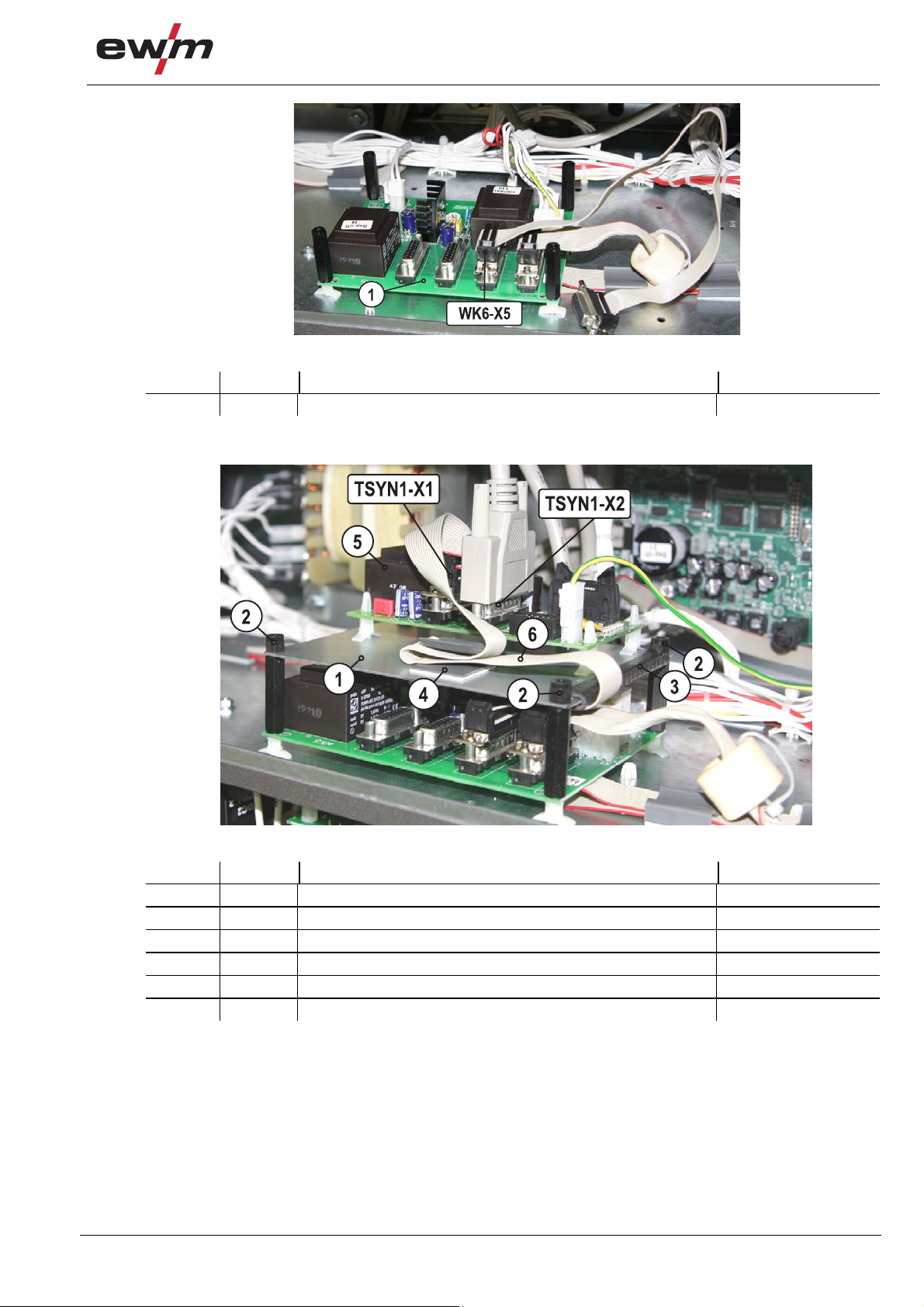
Figure 3-2
Item 0 Quantity Description Item number
1 1 PCB WK 6 2 1 D-SUB cable -
• Remove the D-SUB cable from the WK 6 PCB.
Figure 3-3
Item 0 Quantity Description Item number
1 1 PCB WK 6 2 4 M4 expanding anchor 094-006502-00000
3 4 Spacer M4 x 35 mm 044-002151-00000
• Unfasten the WK 6 PCB from the expanding anchors.
• Replace expanding anchor (without threaded end fitting) with M4 expanding anchor (with threaded end
fitting).
• Attach the WK 6 PCB to the M4 expanding anchors (with threaded end fitting).
• Secure the WK 6 PCB using M4 x 35 mm spacers.
8
099-008212-EW501
14.03.2011
Conversion
Figure 3-4
Item 0 Quantity Description Item number
1 1 PCB WK 6 -
• Attach the D-SUB connection of the flat band cable to the WK6-X5 PCB and screw tight.
Installing the PCB
Item 0 Quantity Description Item number
1 1 PCB holder 094-016978-00000
2 4 Thread bolt M4 x 8 mm 044-003002-00000
3 1 Edge protection 094-007643-00000
4 1 Adhesive base 074-000159-00000
5 1 PCB TSYN1 040-000676-00000
6 1 Flat band cable D-SUB 094-007494-00002
• Attach the PCB holder to the M4 x 35 mm spacers using M4 x 8 mm stud bolts.
• Attach the edge protection to the PCB holder.
• Attach the adhesive base to the PCB holder.
• Attach the D-SUB connection of the flat band cable to the TSYN1-X1 PCB and screw tight (secure the
cable in the adhesive base).
• Reattach the D-SUB cable of the WK 6 PCB to the TSYN1-X2 PCB and screw tight.
099-008212-EW501
14.03.2011
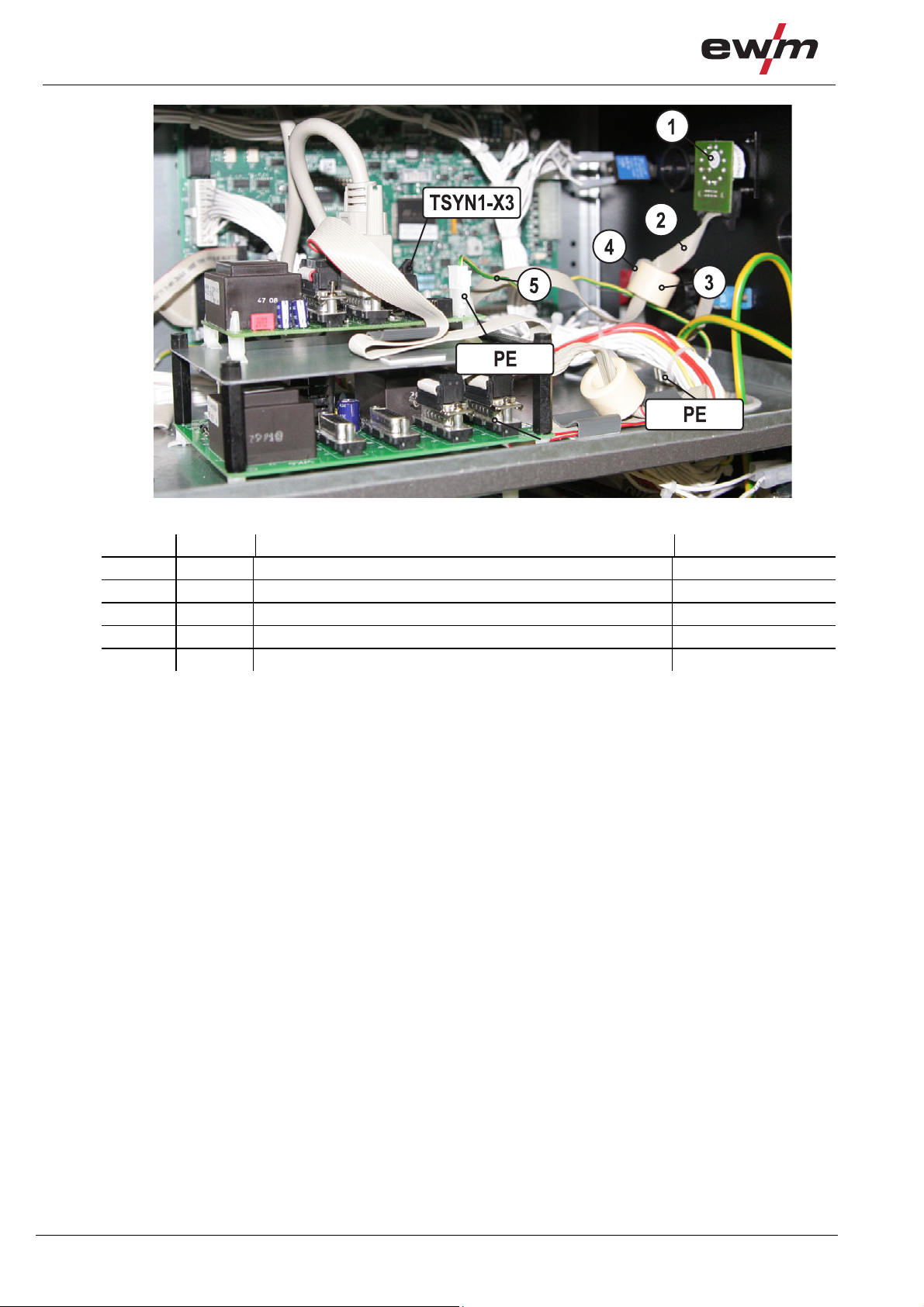
Figure 3-5
9
Conversion
Installing the PCB
Figure 3-6
Item 0 Quantity Description Item number
1 1 Rotary switch (assembly) 092-008178-00000
2 1 Flat band cable 094-000003-00000
3 1 Toroidal ferrite core (interference suppression) 034-000157-00000
4 4 Cable binder 044-001275-00000
5 1 Earthing cable (PE) 094-016979-00000
• Insert the flat band cable connector plug through the toroidal ferrite core and secure usin g a cable
binder.
• Lay the flat band cable to the TSYN1-X3 PCB, insert and lock.
• Connect the earthing cable of the TSYN1-PE PCB to the PE earthing contact on the intermediate
plate.
• Secure the harness using the cable binder supplied
10
099-008212-EW501
14.03.2011

3.2.2 Tetrix 451, 551 AC/DC
Conversion
Installing the PCB
7
6
4
3
2
TSYN1-X1
TSYN1-X2
5
1
Figure 3-7
Item 0 Quantity Description Item number
1 4 M4 expanding anchor 094-006502-00000
2 1 PCB holder 094-016978-00000
3 4 Spacer M4 x 35 mm 044-002151-00000
4 1 Edge protection 094-007643-00000
5 4 Spacer 064-000567-00000
6 1 PCB TSYN1 040-000676-00000
7 1 Flat band cable D-SUB 094-007494-00002
• Attach the M4 expanding anchor to the intermediate plate.
• Secure the PCB holder to the M4 expanding anchor using the M4 x 35 mm spacer.
• Insert the spacer into the PCB holder.
• Fit the TSYN1 PCB on the spacer.
• Attach the edge protection to the PCB holder.
• Attach the D-SUB connection of the flat band cable to the TSYN1-X2 PCB and screw tight.
• Attach the D-SUB connection of the flat band cable of the WK 6 PCB to the TSYN1-X1 PCB and
screw tight.
099-008212-EW501
14.03.2011
11
Conversion
Installing the PCB
1
2
4
5
3
TSYN1-X3
PE
TSYN1-PE
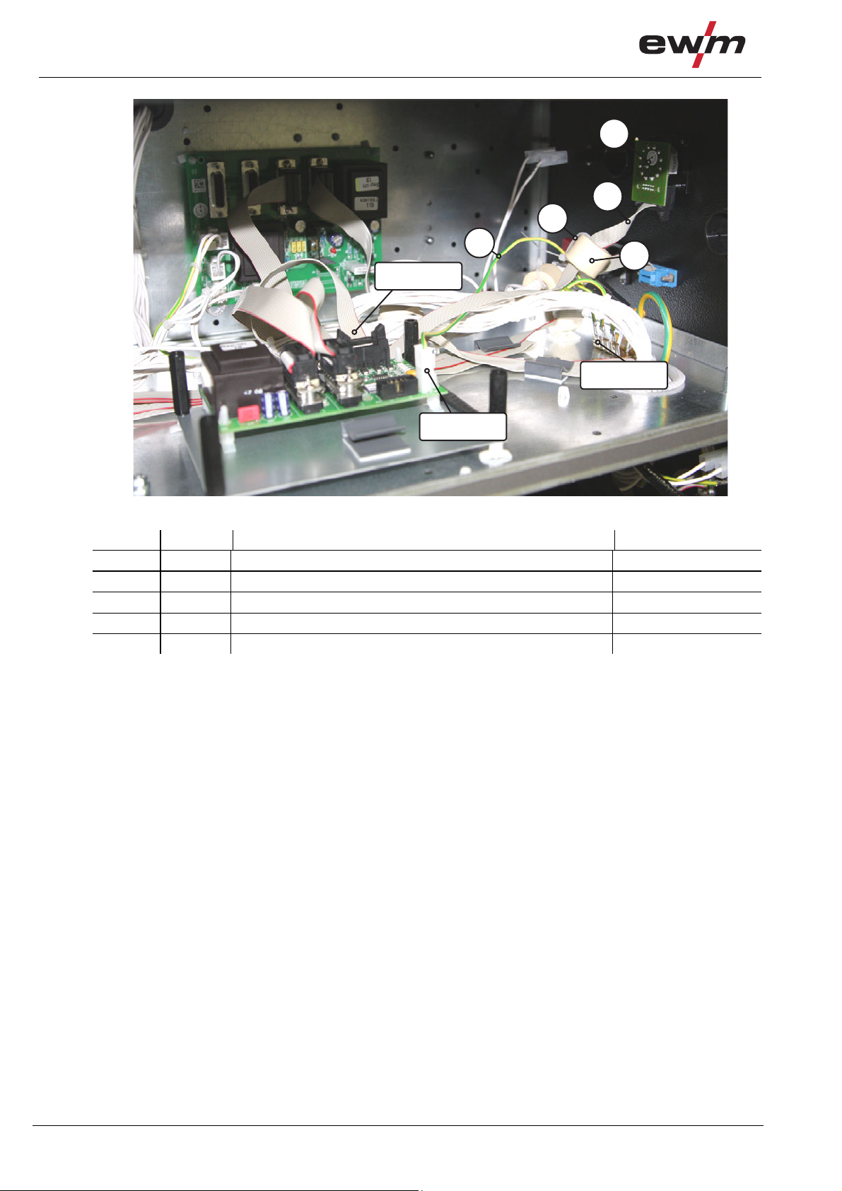
Figure 3-8
Item 0 Quantity Description Item number
1 1 Rotary switch (assembly) 092-008178-00000
2 1 Flat band cable 094-000003-00000
3 1 Toroidal ferrite core (interference suppression) 034-000157-00000
4 2 Cable binder 044-001275-00000
5 1 Earthing cable (PE) 094-016979-00000
• Insert the flat band cable connector plug through the toroidal ferrite core and secure usin g a cable
binder.
• Lay the flat band cable to the TSYN1-X3 PCB, insert and lock.
• Connect the earthing cable of the TSYN1-PE PCB to the PE earthing contact on the intermediate
plate.
• Secure the harness using the cable binder supplied
12
099-008212-EW501
14.03.2011
Installing the rotary switch at the back of the machine
3.3 Installing the rotary switch at the back of the machine
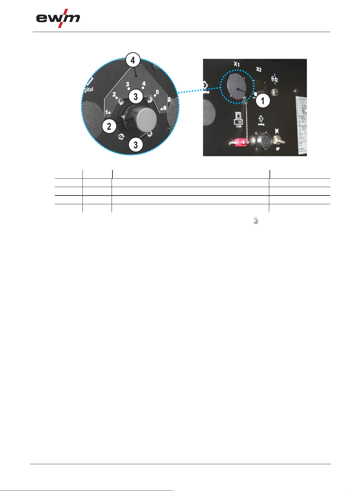
Figure 3-9
Item 0 Quantity Description Item number
1 1 Blind plug
2 1 Rotary switch (assembly) 092-008178-00000
3 4 Oval-head screw M3x10 044-001414-00001
4 1 Adhesive film (rotary switch) 094-009599-00000
• Remove the blind plug from the X1 connection (with older machines, the symbol may be shown
instead of X1).
• Remove the rotary dial cover and arrow indicator from the rotary switch.
• Insert the rotary switch from inside the casing rear panel and secure from the outside using the ovalhead screws.
The step switch is equipped with a switching stage limiter nipple, which has to point to the right
during installation.
• Attach the sticker above the rotary switch at the casing rear panel (see figure).
• Reattach the rotary dial and arrow indicator to the rotary switch.
To align the rotary dial with the sticker scale proceed as follows:
• Using a socket wrench, screw the rotary dial tight up to the point that the steps can be switched.
• Turn the rotary dial to the different switch positions to the left until it overwinds.
• Continue turning until the arrow indicator points to position 1 again.
• Screw the rotary dial tight.
• Fit on the rotary dial cover.
• Attach the flat band cable connector plug to the VP13-X1 PCB (rotary switch) and lock.
• Assemble the machine in the reverse order.
Conversion
099-008212-EW501
14.03.2011
13

Final inspection
Installing the rotary switch at the back of the machine
4 Final inspection
Protective earth PE!
To protect persons and animals against dangerous live voltages and electric shocks in
the event of a fault, the casing panels on the unit are connected to a green/yellow
protective earth.
• After conversion, re-connect the protective earth to the casing panels!
Danger due to failure to carry out the final inspection!
After installation or conversion, all mechanical and electrical connections must be
checked for correct installation to avoid any potential injuries.
• No leads or tubes should be squashed or laid on sharp ed ges.
• Check all mechanical connections to ensure that they are fitted correctly!
• Carry out the final inspection!
• Carry out the functional test!
CAUTION
Test!
Before re-commissioning, it is essential that an "inspection and test during operation"
is carried out conforming to IEC / DIN EN 60974-4 "Arc welding devices - inspection and
testing during operation"!
• For detailed instructions, please see the standard operating instruct ions for the welding
machine.
NOTE
• Keep the conversion instructions with the machine documentation!
• When ordering spare parts, ensure that the item number and serial number of the
machine are quoted!
DANGER
WARNING
14
099-008212-EW501
14.03.2011

5 Appendix
5.1 Circuit diagram
X8
X8/2
Appendix
Circuit diagram
7734-00
Zeichnungsnummer:
W K - 6
X4
D-Sub.
15polig
X5
D-Sub.
15polig
od.
X1
X4/10
X4/9
X4/8
X4/7
X4/6
X4/5
X4
X4/4
X4/3
X4/2
X4/1
X6
D-Sub.
15polig
od.
15polig
D-Sub.
Bus Eingang
A1-
Programmierstecker
T S Y N - 1
X7
X2
Bus Ausgang
X5
PE
D-Sub.
15polig
od.
15polig
D-Sub.
or communicated or forwarded to third parties
without our express permission!
NACHRUESTUNG NETSYNCHRON
It may not be reproduced or utilised in any way
This drawing is protected by copyright.
X11/26
-15V
X11/25
-15V
X11/24
+15V
X11/23
+15V
X11/22
+5V1
X11/21
+5V1
X11/20
0V1
X11/19
0V1
X11/18
+10V Uref.
X11/17
+10V Uref.
X11/16
0V-Ana.
X11/15
0V-Ana.
X11/14
OE
X11/13
Ana. C
Ana. B
Ana. A
A2
B2
A1
B1
CLK1
CLK1
A1-X5/
X5/2
X5/1
PE
CS2
CS1
RD1
WR1
X11/9
X11/8
X11/7
X11/6
X11/5
X11/4
X11/3
X11/2
X11/1
D-Sub.
15polig
X11
X11/12
X11/11
Frontplatte
X11/10
X8
Systembus
Datum: Name:
25.01.2011 NIEDENTHAL
11
Blatt: /
gezeichnet:
DETAILZEICHNUNG TETRIX 35X/45X/55X AC/DC
REIBEL
25.01.2011
Änderung-
Änderung-
Änderung-
Änderung-
geprüft von:
Wählschalter
X3
X3/1
X3/2
X3/3
X3/4
X3/5
0°
60°
120°
180°
240°
Ringkern
0°
60°
120°
180°
240°
X1/1
X1/2
X1/3
X1/4
X1/5
X1
1234567
A
X3/6
300°
300°
X1/6
X3/7
NC
NC
X1/7
X3/8
NC
NC
X1/8
8
X3/9
X3/10
+5V
+5V
+5V
+5V
X1/9
X1/10
S1
8pol. Umschalter
A2-
V P 1 3
X2/4
X2/3
X2/2
X2/1
X14/12
X14/11
X14/10
X14/9
X14/8
X14/7
X14/6
X14/5
X14/4
X14/3
X14/2
X14/1
T 3 2 0 / 1
X2
Lüfter
X14
Peripherie
Computer
X7
9polig
D-Sub.
099-008212-EW501
14.03.2011
15
 Loading...