

EWM PICO 162, PICO 162 MV, PICOTIG 230 AC/DC POWERSINUS TGD, PICOTIG 190 AC/DC TGD Operating Instructions Manual

EWM
HIGHTEC WELDING GmbH
Dr. Günter-Henle-Straße 8 D-56271 Mündersbach
Fon +49 2680 181-0 Fax +49 2680 181-244
www.ewm.de info@ewm.de
GB
Operating instructions
Welding machines for MMA welding
PICO 162
PICO 162 MV
N. B. These operating instructions must be read before commissioning.
Failure to do so may be dangerous.
Machines may only be operated by personnel who are familiar with the appropriate safety
regulations.
The machines bear the conformity mark and thus comply with the
• EC Low Voltage Directive (2006/95/ EG)
• EC EMC Directive (2004/108/ EG)
In compliance with IEC 60974, EN 60974, VDE 0544 the machines can be used in environments
with an increased electrical hazard.
©
The content of the operating instructions does not constitute grounds for any claims on the part
of the buyer.
The copyright to these operating instructions remains with the manufacturer.
Reprinting, including extracts, only with written approval.
© 2009 Subject to alteration.
Item No.: 099-002040-EWM01
Revised: 2009-03-10

Mündersbach, 25 February 2009
Dear customer,
Thank you for your order.
Premium quality – made in Germany and with a three-year warranty.
The machines from EWM are impressive, with innovative technology, exceptional user-friendliness an d
the most up to date inverter and control systems. This makes welding possible that is simple, efficient
and resource-saving as well as being highly economical!
Perfection doesn't happen by coincidence: Every single component is 100% tested and the machine is
“free welded” before it is delivered.
Our comprehensive service offer and the highly developed modern EWM quality management system
guarantee worldwide premium quality “Made in Germany” and a three-year warranty.
Continual further development and optimisation has made us Germany’s market leader in the
manufacture of light arc welding machines. We have manufacturing, training and service locations
throughout the world to advise you and provide you with a comprehensive range of services.
The accompanying operating instructions contain everything about commissionin g the machine, notes
regarding safety, maintenance and care, technical data as well as information regarding the warranty. It
is very important to observe all our instructions in order to achieve optimal welding results with the
machine and to ensure many years of safe operation.
Thank you for the trust that you have placed in us. We look forward to a long-term and, above all,
successful partnership with you.
Yours faithfully
EWM HIGHTEC WELDING GmbH
Bernd Szczesny
Executive management

Machine and Company Data
Please enter the EWM machine data and your company’s data in the appropriate fields.
CE
EWM HIGHTEC WELDING GMBH
D-56271 MÜNDERSBACH
TYP:
ART:
SNR:
PROJ:
GEPRÜFT/CONTROL:
Name of Customer / company
Adress
Post code / Place
Country
Stamp / Signature of EWM-distibutor
Date of purchase
Name of Customer / company
Adress
Post code / Place
Country
Stamp / Signature of EWM-distibutor
Date of purchase
3

Contents
Notes on the use of these operating instructions
4 Item No.: 099-002040-EWM01
1 Contents
1 Contents..................................................................................................................................................4
2 Safety instructions.................................................................................................................................6
2.1 Notes on the use of these operating instructions...........................................................................6
2.2 General...........................................................................................................................................8
2.3 Transport and installation.............................................................................................................11
2.4 Ambient conditions.......................................................................................................................12
2.4.1 In operation...................................................................................................................12
2.4.2 Transport and storage ..................................................................................................12
3 Technical data.......................................................................................................................................13
3.1 PICO 162, PICO 162 MV.............................................................................................................13
4 Machine description.............................................................................................................................14
4.1 PICO 162, PICO 162 MV.............................................................................................................14
4.1.1 Front view.....................................................................................................................14
4.1.2 Rear view......................................................................................................................15
5 Functional characteristics...................................................................................................................16
5.1 Machine control – Operating elements........................................................................................16
5.2 MMA welding................................................................................................................................16
5.2.1 Selecting MMA welding ................................................................................................16
5.2.2 Arcforcing......................................................................................................................16
5.2.3 Hotstart device..............................................................................................................16
5.2.4 Antistick.........................................................................................................................17
5.3 TIG welding..................................................................................................................................17
5.3.1 TIG welding selection ...................................................................................................17
5.3.2 TIG arc ignition .............................................................................................................17
6 Commissioning.....................................................................................................................................18
6.1 General.........................................................................................................................................18
6.2 Area of application – proper usage..............................................................................................18
6.3 Installation....................................................................................................................................19
6.4 Mains connection.........................................................................................................................19
6.4.1 PICO 162, PICO 162 MV..............................................................................................19
6.5 Machine cooling...........................................................................................................................19
6.5.1 Dirt filter.........................................................................................................................20
6.6 Workpiece lead, general ..............................................................................................................21
6.7 MMA welding................................................................................................................................21
6.7.1 PICO 162, PICO 162 MV..............................................................................................21
6.7.1.1 Electrode holder connection..........................................................................22
6.7.1.2 Connection for workpiece lead......................................................................22
6.8 TIG welding..................................................................................................................................23
6.8.1 PICO 162, PICO 162 MV..............................................................................................23
6.8.1.1 Connecting a TIG welding torch with rotating gas valve...............................23
6.8.1.2 Connection for workpiece lead......................................................................23
6.8.1.3 Shielding Gas Supply....................................................................................24

Contents
Notes on the use of these operating instructions
Item No.: 099-002040-EWM01 5
7
Maintenance and testing.....................................................................................................................25
7.1 General........................................................................................................................................25
7.2 Cleaning.......................................................................................................................................25
7.3 Test..............................................................................................................................................26
7.3.1 Test equipment.............................................................................................................26
7.3.2 Scope of the test...........................................................................................................27
7.3.3 Visual inspection...........................................................................................................27
7.3.4 Measuring the open circuit voltage...............................................................................27
7.3.5 Measurement of insulation resistance..........................................................................27
7.3.6 Measuring the leakage current (protective conductor and contact current).................28
7.3.7 Measurement of protective conductor resistance ........................................................28
7.3.8 Functional test of the welding machine........................................................................28
7.3.9 Documentation of the test ............................................................................................28
7.4 Repair Work.................................................................................................................................29
7.5 Disposing of equipment...............................................................................................................30
7.5.1 Manufacturer's declaration to the end user..................................................................30
7.6 Meeting the requirements of RoHS.............................................................................................30
8 Warranty................................................................................................................................................31
8.1 General Validity............................................................................................................................31
8.2 Warranty Declaration...................................................................................................................32
9 Operating problems, causes and remedies ......................................................................................33
9.1 General........................................................................................................................................33
9.2 Error messages (power source) ..................................................................................................33
9.3 Customer checklist.......................................................................................................................34
10 Accessories, options...........................................................................................................................35
10.1 MMA welding ...............................................................................................................................35
10.2 TIG welding..................................................................................................................................35
10.3 Options.........................................................................................................................................35
10.4 General accessories....................................................................................................................35
11 Circuit diagrams...................................................................................................................................36
11.1 PICO 162 .....................................................................................................................................36
11.2 PICO 162 MV...............................................................................................................................37
12 Appendix A ...........................................................................................................................................38
12.1 Declaration of Conformity ............................................................................................................38

Safety instructions
Notes on the use of these operating instructions
6 Item No.: 099-002040-EWM01
2 Safety instructions
2.1 Notes on the use of these operating instructions
NOTE
Special technical points which users must observe.
• Notes include the "NOTE" keyword in the heading without a general warning symbol.
• Notes are highlighted using a "hand" symbol at the edge of the page.
CAUTION
Working and operating procedures which must be followed precisely to avoid damaging
or destroying the product.
• The safety information includes the "CAUTION" keyword in its heading without a general
warning symbol.
• The hazard is explained using a symbol at the edge of the page.
CAUTION
Working or operating procedures which must be closely observed to prevent possible
minor personal injury.
• The safety information includes the "CAUTION" keyword in its heading with a general
warning symbol.
• The risk is explained using a symbol on the edge of the page.
CAUTION
Working or operating procedures which must be closely observed to prevent serious
and even fatal injuries.
• Safety notes include the "WARNING" keyword in the heading with a general warning
symbol.
• The hazard is also highlighted using a symbol on the edge of the page.
DANGER
Working or operating procedures which must be closely observed to prevent imminent
serious and even fatal injuries.
• Safety notes include the "DANGER" keyword in the heading with a general warning symbol.
• The hazard is also highlighted using a symbol on the edge of the page.

Safety instructions
Notes on the use of these operating instructions
Item No.: 099-002040-EWM01 7
Instructions and lists detailing step-by-step actions in given situations can be recogni sed by bullet points,
e.g.:
• Insert the welding current lead socket into the relevant socket and lock.
Symbol Description
Press
Do not press
Turn
Switch

Safety instructions
General
8 Item No.: 099-002040-EWM01
2.2 General
CAUTION
Risk of accidents if these safety instructions are not observed!
Non-observance of these safety instructions is potentially fatal!
• Carefully read the safety information in this manual!
• Observe the accident prevention regulations in your country.
• Inform persons in the working area that they must observe the regulations!
CAUTION
Obligations of the operator!
In the European Economic Area (EEA), the relevant national version of the basic
guidelines must be followed and observed!
• National version of the basic guidelines (89/391/EEC) as well as the relevant individual
guidelines.
• In particular the Directive (89/655/EEC) on the minimum regulations for safety and health
protection when staff members are using equipment during work.
• The accident prevention regulations of the relevant country (e.g. in Germany, BGV D 1).
• Check at regular intervals that users are working in a safety-conscious way!
Damage due to the use of non-genuine parts!
The manufacturer's warranty becomes void if non-genuine parts are used!
• Only use system components and options (power sources, welding torche s, electrode
holders, remote controls, spare parts and replacement parts, etc.) from our range of
products!
Electromagnetic interference!
The machines are intended to be used in industrial areas, according to IEC 60974-10. If
they are used in residential areas, for example, problems may occur with ensuring
electromagnetic compatibility.
• Check whether interference is caused to other machines!
CAUTION
Noise exposure!
Noise exceeding 70 dBA can cause permanent hearing damage!
• Wear suitable ear protection!
• Persons located within the working area must wear suitable ear protection!

Safety instructions
General
Item No.: 099-002040-EWM01 9
CAUTION
Risk of injury due to radiation or heat!
Arc radiation results in injury to skin and eyes.
Contact with hot workpieces and sparks results in burns.
• Wear dry protective clothing (e.g. welding shield, gloves, etc.) according to the relevant
regulations in the country in question!
• Protect persons not involved in the work against arc beams and the risk of glare using safety
curtains!
Explosion risk!
Apparently harmless substances in closed containers may generate exces sive pressure
when heated.
• Move containers with inflammable or explosive liquids away from the working area!
• Never heat explosive liquids, dusts or gases by welding or cutting!
Smoke and gases!
Smoke and gases can lead to breathing difficulties and poisoning. In addition, solvent
vapour (chlorinated hydrocarbon) may be converted into poisonous phosgene due to the
ultraviolet radiation of the arc!
• Ensure that there is sufficient fresh air!
• Keep solvent vapour away from the arc beam field!
• Wear suitable breathing apparatus if appropriate!
Fire hazard!
Flames may arise as a result of the high temperatures, stray sparks, glowing-hot parts
and hot slag produced during the welding process.
Stray welding currents can also result in flames forming!
• Check for fire hazards in the working area!
• Do not carry any easily flammable objects such as matches or lighters.
• Keep appropriate fire extinguishing equipment to hand in the working area!
• Thoroughly remove any residue of flammable substances from the workpiece before starting
welding.
• Only continue work on welded workpieces once they have cooled down.
Do not allow to come into contact with flammable material!
• Connect welding leads correctly!

Safety instructions
General
10 Item No.: 099-002040-EWM01
DANGER
Electromagnetic fields!
The power source may cause electrical or electromagnetic fields to be produced which
could affect the correct functioning of electronic equipment such as IT or CNC devices,
telecommunication lines, power cables, signal lines and pacemakers.
• Observe the maintenance instructions! (see Maintenance and Testing chapter)
• Unwind welding lines completely!
• Shield devices or equipment sensitive to radiation accordingly!
• The correct functioning of pacemakers may be affected (obtain advice from a doctor if
necessary).
Do not carry out any unauthorised repairs or modifications!
To avoid injury and equipment damage, the unit must only be repaired or modified by
specialist, skilled persons!
The warranty becomes null and void in the event of unauthorised interference.
• Appoint only skilled persons for repair work (trained service personnel)!
Electric shock!
Welding machines use high voltages which can result in potentially fatal electric shocks
and burns on contact. Even low voltages can cause you to get a shock and lead to
accidents.
• Do not touch any live parts in or on the machine!
• Connection cables and leads must be free of faults!
• Switching off alone is not sufficient! Wait for 2 minutes until the capacitors have discharged.
• Place welding torch and stick electrode holder on an insulated surf ace!
• The unit should only be opened by specialist staff after the mains plug has been unplugged!
• Only wear dry protective clothing!

Safety instructions
Transport and installation
Item No.: 099-002040-EWM01 11
2.3 Transport and installation
CAUTION
Equipment damage when not operated in an upright position!
The units are designed for operation in an upright position!
Operation in non-permissible positions can cause equipment damage.
• Only transport and operate in an upright position!
CAUTION
Risk of tipping!
There is a risk of the machine tipping over and injuring persons or being damaged itself
during movement and set up. Tilt resistance is guaranteed up to an angle of 10°
(according to IEC 60974-1, -3, -10).
• Set up and transport the machine on level, solid ground.
• Secure add-on parts using suitable equipment.
Damage due to supply lines not being disconnected!
During transport, supply lines which have not been disconnected (mains supply leads,
control leads, etc.) may cause hazards such as connected equipment tipping over and
injuring persons!
• Disconnect supply lines!
CAUTION
Incorrect handling of shielding gas cylinders!
Incorrect handling of shielding gas cylinders can result in serious and even fatal injury.
• Observe the instructions from the gas manufacturer and in any relevant regulations
concerning the use of compressed air!
• Place shielding gas cylinders in the holders provided for them and secure with fixing
devices.
• Avoid heating the shielding gas cylinder!
Safety instructions
Ambient conditions
12 Item No.: 099-002040-EWM01
2.4 Ambient conditions
CAUTION
Equipment damage due to dirt accumulation!
Unusually high quantities of dust, acid, corrosive gases or substances may damage the
equipment.
• Avoid high volumes of smoke, vapour, oil vapour and grinding dust!
• Avoid ambient air containing salt (sea air)!
Non-permissible ambient conditions!
Insufficient ventilation results in a reduction in performance and equipment damage.
• Observe the ambient conditions!
• Keep the cooling air inlet and outlet clear!
• Observe the minimum distance of 0.5 m from obstacles!
Installation site!
The machine must not be operated in the open air and must only be set up and operated
on a suitable, stable and level base!
• The operator must ensure that the ground is non-slip and level, and provide sufficient
lighting for the place of work.
• Safe operation of the machine must be guaranteed at all times.
2.4.1 In operation
Temperature range of the ambient air:
• -20 °C to +40 °C
Relative air humidity:
• Up to 50% at 40 °C
• Up to 90% at 20 °C
2.4.2 Transport and storage
Storage in an enclosed space, temperature range of the ambient air:
• -25 °C to +55 °C
Relative air humidity
• Up to 90% at 20 °C

Technical data
PICO 162, PICO 162 MV
Item No.: 099-002040-EWM01 13
3 Technical data
3.1 PICO 162, PICO 162 MV
PICO range PICO 162
PICO 162 MV (230 V)
PICO 162 MV (115 V)
Setting range:
TIG Welding current
Welding voltage
MMA Welding current
Welding voltage
10 A to 160 A
10.4 V to 16.4 V
10 A to 150 A
20.4 V to 26.0 V
10 A to 120 A
10.4 V to 14.8 V
10 A to 110 A
20.4 V to 24.4 V
Duty cycle at 20 °C
40 %
45 %
50 %
60 %
100 %
TIG
-
160 A
-
-
120 A
MMA
-
-
150 A
-
120 A
TIG
-
-
120 A
100 A
MMA
110 A
-
90 A
80 A
Duty cycle at 40 °C
30 %
35 %
60 %
100 %
160 A
130 A
100 A
150 A
120 A
100 A
-
120 A
100 A
-
110 A
90 A
80 A
Load alternation
10 min (60% DC
∧
6 min welding, 4 min idle)
Open circuit voltage
105 V
Mains voltage (tolerances)
1 x 230 V
(-40% to +15%)
(162 mV: -20% to +15%)
1 x 240 V
(-40% to +10%)
(162 mV: -20% to +10%)
1 x 115 V
(-15% to +15%)
1 x 110 V
(-15% to +20%)
Frequency
50/60 Hz
Mains fuse (safety fuse, slow-blow)
16 A 25 A
Mains connection lead
H07RN-F3G2.5
Max. connected power
6 kVA
Recommended generator rating
8.1 kVA
cosϕ at Imax / efficiency
0.99 / 88%
Insulation class / protection classification
H / IP 23
Ambient temperature
-20°C to +40°C
Machine cooling / torch cooling
Fan / Gas
Workpiece lead
16 qmm
Dimensions L/W/H
430 x 116 x 224 mm
Weight
4.8 kg (PICO 162 MV: 5.1 kg)
Constructed to standards
IEC 60974-1, -3, -10
/

Machine description
PICO 162, PICO 162 MV
14 Item No.: 099-002040-EWM01
4 Machine description
4.1 PICO 162, PICO 162 MV
4.1.1 Front view
2
3
4
5
6
1
Figure 4-1
Item Symbol Description 0
1
Carrying strap
2
Machine control
See Machine control – operating elements chapter
3
Connection socket, "+" welding current
• TIG: Connection for workpiece lead
• MMA: Electrode holder or workpiece lead connection
4
Cooling air outlet
5
Machine feet
6
Connection socket, "-" welding current
• MMA welding: Electrode holder or workpiece lead connection
• TIG welding: Welding current lead connection for TIG welding torch

Machine description
PICO 162, PICO 162 MV
Item No.: 099-002040-EWM01 15
4.1.2 Rear view
2
3
1
Figure 4-2
Item Symbol Description 0
1
Strain relief with mains connection cable
2
Cooling air inlet
3
Main switch, machine on/off

Functional characteristics
Machine control – Operating elements
16 Item No.: 099-002040-EWM01
5 Functional characteristics
5.1 Machine control – Operating elements
20
40
60
80
10 0
120
140
160
S
AMP
2
3
4
1
Figure 5-1
Item Symbol Description 0
1
20
40
60
80
100
120
140
160
AMP
Welding current rotary dial
Infinite adjustment of the welding current from 10A to maximum current
2
Welding process changeover switch
•
= MMA welding
•
= TIG welding
3
Ready for operation signal light
Signal light on when the machine is switched on and ready for operation
4
“Functional error” signal light
For error messages, see chapter on Troubleshooting, causes and remedies
5.2 MMA welding
5.2.1 Selecting MMA welding
Operating
element
Action Result
MMA
welding process selected
20
40
60
80
100
120
140
160
AMP
Main current setting
5.2.2 Arcforcing
During the welding process, arcforce prevents the electrode sticking in the weld pool with increases in
current. This makes it easier to weld large-drop melting electrode types at low current strengths with a
short arc in particular.
5.2.3 Hotstart device
The hotstart device uses an increased ignition current to improve arc ignition. There are presets
for the optimum hotstart current and hotstart time parameters on the machine.
After striking the stick electrode, the arc will ignite with the hotstart current and will then drop to the main
current setting.
Functional characteristics
TIG welding
Item No.: 099-002040-EWM01 17
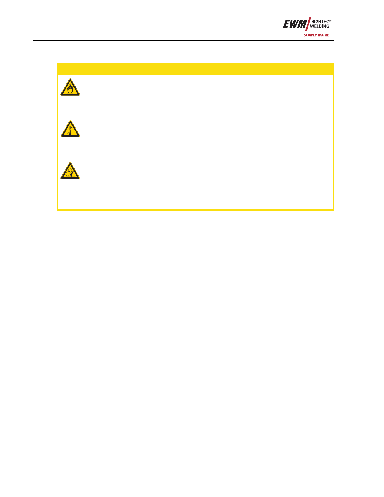
5.2.4 Antistick
Anti-stick prevents the electrode from annealing.
If the electrode sticks in spite of the Arcforce device, the
machine automatically switches over to the minimum
current within about 1 second to prevent the electrode
from overheating. Check the welding current setting
and correct according to the welding task!
Figure 5-2
5.3 TIG welding
5.3.1 TIG welding selection
Operating
Element
Action Result
TIG
welding process selected
20
40
60
80
100
120
140
160
AMP
Main current setting
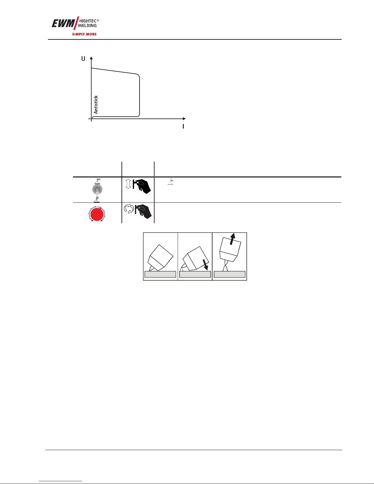
5.3.2 TIG arc ignition
a) b) c)
Figure 5-3
The arc is ignited on contact with the workpiece:
a) Carefully place the torch gas nozzle and tungsten electrode tip onto the workpiece (liftarc current
flowing, regardless of the main current set).
b) Incline the torch towards the torch gas nozzle until there is a gap of approx. 2-3mm between the tip of
the electrode and the workpiece (arc ignites, current increases to the main current set).
c) Lift off the torch and swivel to the normal position.
Ending the welding process: Remove the torch from the workpiece until the arc goes out.

Commissioning
General
18 Item No.: 099-002040-EWM01
6 Commissioning
6.1 General
DANGER
Risk of injury from electric shock!
Contact with live parts, e.g. welding current sockets, is potentially fatal!
• Follow safety instructions on the opening pages of the operating instructions.
• Commissioning may only be carried out by persons who have the relevant expertise of
working with arc welding machines!
• Connection and welding leads (e.g. electrode holder, welding torch, workpiece lead,
interfaces) may only be connected when the machine is switched off!
CAUTION
Risk of burns on the welding current connection!
If the welding current connections are not locked, connections and leads heat up and can
cause burns, if touched!
• Check the welding current connections every day and lock by turning in clockwise direction, if
necessary.
CAUTION
Damage due to the use of non-genuine parts!
The manufacturer's warranty becomes void if non-genuine parts are used!
• Only use system components and options (power sources, welding torche s, electrode
holders, remote controls, spare parts and replacement parts, etc.) from our range of
products!
Using protective dust caps!
Protective dust caps protect the connection sockets and therefore the machine against
dirt and damage.
• The protective dust cap must be fitted if there is no accessory component being operated on
that connection.
• The cap must be replaced if faulty or if lost!
6.2 Area of application – proper usage
CAUTION
Hazards due to improper usage!
Hazards may arise for persons, animals and material objects if the equipment is not used
correctly. No liability is accepted for any damages arising from improper usage!
• The equipment must only be used in line with proper usage and by trained or expert staff!
• Do not modify or convert the equipment improperly!
This welding machine is suitable only for MMA and TIG welding with liftarc.
• MMA direct current welding for rutile, rutile/basic, basic and rutile/cellulose electrode types.

Commissioning
Installation
Item No.: 099-002040-EWM01 19
6.3 Installation
CAUTION
Installation site!
The machine must not be operated in the open air and must only be set up and operated
on a suitable, stable and level base!
• The operator must ensure that the ground is non-slip and level, and provide sufficient
lighting for the place of work.
• Safe operation of the machine must be guaranteed at all times.
6.4 Mains connection
CAUTION
Operating voltage - mains voltage!
The operating voltage shown on the rating plate must be consistent with the mains
voltage, in order to avoid damage to the machine!
• For mains fuse protection, please refer to the “Technical data” chapter!
• Insert mains plug of the switched-off machine into the appropriate socket.
6.4.1 PICO 162, PICO 162 MV
CAUTION
Connect a suitable mains plug!
A suitable mains plug must be connected to the mains supply lead to avoid damage!
• The connection must be made by a qualified electrician in compliance with the laws and
regulations applying in that country.
• Any phase sequence is possible with these three-phase machines.
6.5 Machine cooling
To obtain an optimal duty cycle from the power components, the following precautions should be
observed:
• Ensure that the working area is adequately ventilated.
• Do not obstruct the air inlets and outlets of the machine.
• Do not allow metal parts, dust or other objects to get into the machine.

Commissioning
Machine cooling
20 Item No.: 099-002040-EWM01
6.5.1 Dirt filter
NOTE
These accessory components can be retrofitted as an option, see Accessories chapter.
The dirt filter can be used in places with unusually high levels of dirt and dust in the ambient air.
The filter reduces the duty cycle of the welding machine via the reduced flow of cooling air. The
filter must be disassembled and cleaned regularly depending on the level of dirt (blow out with
compressed air).
2
3
1
Figure 6-1
• As shown in the diagram, insert the dirt filter into the rear of the machine, above the air inlet, using
both clips (1).
• Fold down the dirt filter (2).
• Fasten the dirt filter to the underside of the machine (3) using fixing screws.

Commissioning
Workpiece lead, general
Item No.: 099-002040-EWM01 21
6.6 Workpiece lead, general
CAUTION
Risk of burns due to incorrect connection of the workpiece lead!
Paint, rust and dirt on the connection restrict the power flow and may lead to stray
welding currents.
Stray welding currents may cause fires and injuries!
• Clean the connections!
• Fix the workpiece lead securely!
• Do not use structural parts of the workpiece as a return lead for the welding current!
• Take care to ensure faultless power connections!
6.7 MMA welding
6.7.1 PICO 162, PICO 162 MV
1
2
Figure 6-2
Item Symbol Description 0
1
Connection socket, "+" welding current
• TIG: Connection for workpiece lead
• MMA: Electrode holder or workpiece lead connection
2
“-” Welding current connection socket
Electrode holder or workpiece lead connection

Commissioning
MMA welding
22 Item No.: 099-002040-EWM01
6.7.1.1 Electrode holder connection
CAUTION
Risk of being crushed or burnt.
When replacing spent or new stick electrodes
• Switch off machine at the main switch
• Wear appropriate safety gloves
• Use insulated tongs to remove spent stick electrodes or to move welded workpieces and
• Always put the electrode holder down on an insulated surface.
• Insert cable plug of the electrode holder into either the "+" or "-" welding current connection socket and
lock by turning to the right.
NOTE
Polarity depends on the instructions from the electrode manufacturer given on the
electrode packaging.
6.7.1.2 Connection for workpiece lead
• Insert cable plug of the workpiece lead into either the "+" or "-" welding current connection socket and
lock by turning to the right.
NOTE
Polarity depends on the instructions from the electrode manufacturer given on the
electrode packaging.

Commissioning
TIG welding
Item No.: 099-002040-EWM01 23
6.8 TIG welding
6.8.1 PICO 162, PICO 162 MV
1
2
Figure 6-3
Item Symbol Description 0
1
Connection socket, “+” welding current
Connection for workpiece lead
2
“-” Welding current connection socket
TIG welding torch welding current lead connection
6.8.1.1 Connecting a TIG welding torch with rotating gas valve
When pausing work, always place the welding torch on an insulated surface.
Prepare the welding torch according to the welding task in hand (see torch operating
instructions).
The welding torch shielding gas is supplied directly from the shielding gas cylinder.
• Fit the tungsten electrode and gas nozzle onto the welding torch (observe current load, see torch
operating instructions).
• Insert the welding current plug into the “-” welding current connection socket and lock by turning to the
right.
6.8.1.2 Connection for workpiece lead
• Insert cable p
lug of the workpiece lead into the "+" or "-" welding current socket and lock by turning to
the right.
Polarity depends on the instructions from the electrode manufacturer given on the electrode
packaging.

Commissioning
TIG welding
24 Item No.: 099-002040-EWM01
6.8.1.3 Shielding Gas Supply
CAUTION
Incorrect handling of shielding gas cylinders!
Incorrect handling of shielding gas cylinders can result in serious and even fatal injury.
• Observe the instructions from the gas manufacturer and in any relevant regulations
concerning the use of compressed air!
• Place shielding gas cylinders in the holders provided for them and secure with fixing
devices.
• Avoid heating the shielding gas cylinder!
NOTE
Before connecting the pressure reducer to the gas cylinder, open the cylinder valve
briefly to expel any dirt.
• Tighten the pressure reducer screw connection on the gas bottle valve to be gas-tight.
• Tighten gas hose on pressure reducer to be gas tight.
• Slowly open the gas cylinder valve.
• Open the rotating valve on the welding torch
Before each welding process, the rotating valve must be opened; after the welding process, it
must be closed.
• Set the required amount of shielding gas on the pressure reducer, about 4 - 15 l/min depending on the
current strength and the material.
Rule of thumb for gas flow rate:
Diameter of gas nozzle in mm corresponds to gas flow in l/min.
Example: 7 mm gas nozzle corresponds to 7 l/min gas flow

Maintenance and testing
General
Item No.: 099-002040-EWM01 25
7 Maintenance and testing
NOTE
The maintenance, cleaning and testing work described below must be conducted
correctly and on an annual basis in order qualify for claims under the EWM warranty.
7.1 General
When used in the specified environmental conditions and under normal operating conditions, this
machine is largely maintenance-free and requires a minimum of care.
There are some points, which should be observed, to guarantee fault-free operation of your welding
machine. Among these are regular cleaning and checking as descri bed below, depending on the pollution
level of the environment and the length of time the unit is in use.
NOTE
The welding machine may only be cleaned, tested and repairied by competent, capable
personsl.
A capable person is one who, because of his training, knowledge and experience, is able
to recognise the dangers that can occur while testing welding power sources as well as
possible subsequent damage and who is able to implement the required safety
procedures.
In the event of failure to comply with any one of the following tests, the machine must not
be operated again until it has been repaired and a new test has been carried out!
7.2 Cleaning
DANGER
Electric shocks!
Cleaning machines that are not disconnected from the mains can lead to serious injuries!
• Disconnect the machine completely from the mains.
• Remove the mains plug!
• Wait for 2 minutes until the capacitors have discharged.
The individual components should be handled as follows:
Power source:
Depending on the amount of dust, blow out using oil- and moisture-free compressed air.
Electronics: Do not blast electronic components or circuit boards with compressed air but clean them
with a vacuum cleaner instead.
Coolant:
Check for impurities and replace if necessary.
NOTE
Mixing coolants with other liquids or the use of other coolants voids our manufacturer's
guarantee.

Maintenance and testing
Test
26 Item No.: 099-002040-EWM01
7.3 Test
NOTE
Additional machines and add-on parts (e.g. cooling units, wire feed devices, welding
torches,...) should be tested together with the welding power source.
Some points, such as: insulation and protective conductor resistance, can be tested directly at the same
time and it can be ensured that the total leakage current from the welding power source, additional
machines and add-on parts does not exceed the limits.
For this reason, the full process of testing the welding power source is described below. If additional
machines or add-on parts are tested individually, the test points are to be adjusted if necessary (e.g. no
open circuit voltage measurement).
The test should be conducted in accordance with IEC/DIN EN 60974-4 “Arc welding equipment –
Inspection and testing during operation” in accordance with the German Ordinance of Operational Safety.
This standard is not only an international standard but is also specific to arc welding equi pment.
NOTE
The former term of repetition test has been replaced due to a change in the
corresponding standard with “Inspection and testing during operation”.
In addition to the regulations on the test given here, the relevant local laws and
regulations must also be observed.
7.3.1 Test equipment
NOTE
Due to the special conditions of inverter arc welding equipment, not all test equipment is
suitable for testing in accordance with VDE 0702 to the full extent!
EWM as a manufacturer offers all appropriately trained and authorised EWM sales pa rtners the
appropriate test equipment and measuring devices conforming to VDE 0404-2, which evaluate the
frequency response conforming to DIN EN 61010-1 Appendix A – Measuring Circuit A1.
You as the user are tasked with ensuring that your EWM machines conform to the standard IEC/DIN EN
60974-4 and are tested with the relevant test equipment and measuring devices given above.
NOTE
The following description of the test is only a brief overview of the points to be tested.
For details about the test points or in the event of any queries, please refer to
IEC/DIN EN 60974-4.

Maintenance and testing
Test
Item No.: 099-002040-EWM01 27
7.3.2 Scope of the test
a) Visual inspection
b) Electrical test: measurement of
• open circuit voltage
• insulation resistance, or alternatively
• leakage currents
• protective conductor resistance
c) Functional test
d) Documentation
7.3.3 Visual inspection
The key areas in the test are:
1. Torch/stick electrode holder, welding current return lead clamp
2. Power supply: leads including plugs and strain relief
3. Welding current circuit: leads, plugs and couplings, strain relief
4. Casing
5. Operating, message, safety and adjustment devices
6. Other, general condition
7.3.4 Measuring the open circuit voltage
6u8F
10nF
0...5k
0k2
1k0
1N 4007
Measuring circuit according to DIN EN
60974-1
Connect the measuring circuit to the welding current
sockets. The voltmeter must display mean values and
have an internal resistance ≥ 1 MΩ. In the case of step
switch controlled devices, set the maximum output voltage
(step switch). Adjust the potentiometer from 0 kΩ to 5 kΩ
during the measurement. The measured voltage should
not deviate from that specified on the rating plate by more
than +/- 5% and may be no greater than 113 V (for devices
with VRD: 35 V).
7.3.5 Measurement of insulation resistance
The mains switch must be on so that the insulation in the interior of the machine can also be checked
through to the transformer. If a mains contactor is fitted, this should be bridged or the measurement must
be carried out on both sides.
The insulation resistance must not be less than:
Mains current circuit against Welding current circuit and electronics
5 MΩ
Welding current circuit and
electronics
against Protective conductor circui t (PE)
2.5 MΩ
Mains current circuit against Protective conductor circui t (PE)
2.5 MΩ

Maintenance and testing
Test
28 Item No.: 099-002040-EWM01
7.3.6 Measuring the leakage current (protective conductor and contact current)
Note: Even if the leakage current measurement according to the standard is only an alternative to the
insulation resistance measurement, EWM recommends always performing both measurements,
especially following repair work. The leakage current is based for the greater part on a physical effect
other than the insulation resistance. For this reason, it may not be possible to uncover a dangerous
leakage current using the insulation resistance measurement.
These measurements cannot be performed with a normal multimeter. Even test devices for VDE 0702
(especially older devices) are generally only intended for 50/60 Hz. With inverter welding machine s,
however, significantly higher frequencies occur, which can interfere with some measuring devices, and
result in others measuring the frequency incorrectly.
A test device must meet the requirements of VDE 0404-2. For the frequency response measurement,
please refer to DIN EN 61010-1 Appendix A – Measuring circuit A1.
NOTE
For these measurements, the welding machine must be switched on and supplying open
circuit voltage!
1. Protective conductor current: < 5 mA
2. Leakage current from the welding sockets separately to PE: < 10 mA
7.3.7 Measurement of protective conductor resistance
Measure between the plug earthed contact and accessible live parts, e.g. casing screws.
During the measurement, the connection lead must be moved across the entire length, especi ally near
the casing and plug inlet points. This should uncover any interruptions in the protective conductor. All
conductive parts of the casing accessible from outside should also be tested to ensure a correct PE
connection for safety class I.
The resistance must not exceed a mains connection lead 0.3Ω up to 5m in length. For longer leads, the
permissible value increases by 0.1Ω per 7.5m of lead. The maximum permissible value is 1Ω.
7.3.8 Functional test of the welding machine
Safety devices, selector switches and command units (if fitted) and the entire machine or the entire
system for arc welding, must be functioning perfectly.
1. Main switch
2. Emergency stop devices
3. Voltage reducing device
4. Gas solenoid valve
5. Message and control lamps
7.3.9 Documentation of the test
The test report must contain:
• the designation of the tested welding equipment,
• the date of the test,
• the test results,
• the signature, name of technician and the relevant institution,
• the name of the test equipment.
A label with the date of the test must be affixed to the welding machine to show that the test has been
passed.

Maintenance and testing
Repair Work
Item No.: 099-002040-EWM01 29
7.4 Repair Work
Repair and maintenance work may only be performed by qualified authorised personnel; otherwise the
right to claim under the warranty is void. In all service matters, please contact your EMW sales partner.
Returns of defective equipment subject to warranty may only be made through your EWM sales partner.
In the event of problems or queries, please contact the EWM Service Department directly (+49 (0) 2680
181 0). Use only genuine spare parts and replacement parts when replacing. When placing an order,
please quote the type designation and item number, as well as the type, serial number and item number
of the relevant equipment.
We hereby confirm that the servicing and maintenanc e instructions g iven above and the test describe d above have
been completed correctly.
Date/Stamp/Signature of EWM sales partner
Date/Stamp/Signature of EWM sales partner
Date of next maintenance work and test
Date of next maintenance work and test
Date/Stamp/Signature of EWM sales partner
Date/Stamp/Signature of EWM sales partner
Date of next maintenance work and test
Date of next maintenance work and test
Date/Stamp/Signature of EWM sales partner
Date/Stamp/Signature of EWM sales partner
Date of next maintenance work and test
Date of next maintenance work and test

Maintenance and testing
Disposing of equipment
30 Item No.: 099-002040-EWM01
7.5 Disposing of equipment
NOTE
Disposal!
In Germany, waste equipment from private households can be disposed of free of charge
at local community collection points. Your local administration point can provide
information on the options available. EWM participates in an approved waste disposal
and recycling system and is registered in the Used Electrical Equipment Register (EAR)
under number WEEE DE 57686922.
• This equipment must be disposed of in accordance with official regulations.
7.5.1 Manufacturer's declaration to the end user
• According to European provisions (guideline 2002/96/EG of the European Parliament and the Council
of January, 27th 2003), used electric and electronic equipment may no longer be placed in unso rted
municipal waste. It must be collected separately. The symbol depicting a waste container on wheels
indicates that the equipment must be collected separately.
This machine is to be placed for disposal or recycling in the waste separation systems provided for this
purpose.
• According to German law (law governing the distribution, taking back and enviro nmentally corre ct
disposal of electric and electronic equipment (ElektroG) from 16.03.2005), used machines are to be
placed in a collection system separate from unsorted municipal waste. The public waste ma nagement
utilities (communities) have created collection points at which used equipment from private households
can be disposed of free of charge.
• Information about giving back used equipment or about collections can be obtained from the
respective municipal administration office.
• EWM participates in an approved waste disposal and recycling system and is registered in the Used
Electrical Equipment Register (EAR) under number WEEE DE 57686922.
• In addition to this, returns are also possible throughout Europe via EWM sales partners.
7.6 Meeting the requirements of RoHS
We, EWM HIGHTEC Welding GmbH Mündersbach, hereby confirm that all product s su pplied by us which
are affected by the RoHS Directive, meet the requirements of the RoHS (Directive 2002/95/EC).

Warranty
General Validity
Item No.: 099-002040-EWM01 31
8 Warranty
8.1 General Validity
3-year warranty
on all new EWM machines*:
• Power sources
• Wire feeds
• Cooling units
• Trolleys
* If these are operated with genuine EWM accessories (such as intermediate tube package, remote
control, remote control extension cable, coolant, etc.).
1-year warranty on:
• Used EWM machines
• Automation and mechanisation components
• Remote control
• Inverters
• Intermediate tube packages
6-month warranty on:
• Spare parts supplied separately (such as circuit boards, ignition units)
Manufacturer/supplier warranty on:
• All additional parts used by EWM, but manufactured by other companies (e.g. motors, pumps, fans,
torches, etc.)
Non-reproducible software errors and parts subject to mechanical ageing are excluded from the warranty
(e.g. wire feed unit, wire feed rollers, replacement and spare wire feed parts, wheels, solenoid valves,
workpiece leads, electrode holders, connection tubes, replacement torche s and spare torch parts, mains
and control leads, etc.).
These terms shall apply without affecting the customer’s legal rights to a warranty and subject to our
General Terms and Conditions of Business and our terms on the warranty decl aration. Agreements to the
contrary must be confirmed by EWM in writing.
Our General Terms and Conditions of Business are available for access anytime online at www.ewm.de
.

Warranty
Warranty Declaration
32 Item No.: 099-002040-EWM01
8.2 Warranty Declaration
Your 3-year warranty
Regardless of statutory warranty rights and based on our General Terms and Conditions, EWM
HIGHTEC WELDING GmbH provides a 3-year warranty for its welding products starting on the date of
purchase. Different warranty periods apply to accessories and spare parts; please see the “General
Validity” section for these periods. Parts subject to wear are naturally exempt from the warranty.
EWM guarantees the error-free condition of the products in terms of materials and processing. If the
product proves to be defective in terms of materials or processing within the warranty period, you are
entitled to free repair or to replacement with an appropriate product, at our discretion. On receipt by EWM
the returned product becomes the property of EWM.
Condition
The prerequisite for receiving the full 3-year warranty is simply to operate the products in accordance with
the EWM operating instructions observing the relevant legal recommendations and guideline s and having
annual maintenance work and testing conducted by an EWM sales partner (see “Maintenance and
testing” chapter). This is because only machines that are maintained regularly function correctly in the
long term.
Making a claim
When making a claim under the warranty, please contact your EWM authorised sales partner only.
Warranty exclusions
No warranty claims can be accepted if the EWM products in question are not operated using genuine
EWM accessories (such as intermediate tube package, remote control, remote control extension cable,
coolant, etc.). The warranty does not apply to products that are damaged due to accidents, misuse,
improper operation, incorrect installation, use of force, disregard of the specifications and operating
instructions, inadequate maintenance (see chapter “Maintenance and testing”), exterior influences, acts of
God or personal misfortunes. Furthermore, it is not valid in the case of improper changes, repairs or
modifications. In addition, a claim for warranty does not exist in the case of partially or completely
dismantled products and interventions by persons who are not authorised by EWM, as well as in the case
of normal wear.
Limitation
All claims regarding fulfilment or non-fulfilment on the part of EWM from this declaration in connection
with this product are limited as follows to the replacement of the actual damages. EWM’s liability
stemming from this declaration in connection with this product is fundamentally limited to the amount that
the purchaser originally paid for the original purchase. This limitation does not apply to personal injuries
or damage to property caused by negligent behaviour on the part of EWM. In no way will EWM be
responsible for lost profits, indirect or subsequent damage. EWM is not liable for dama ges based on the
claims of third parties.
Place of jurisdiction
If the person making the claim is a business person, the sole place of jurisdiction for all disputes resulting
directly or indirectly from the contractual relationship shall be the headquarters or the branch of fice of the
supplier, at the discretion of the supplier. The purchaser gains ownership of the products supplied as
replacements within the framework of the warranty adjustment at the time of the exchange.

Operating problems, causes and remedies
General
Item No.: 099-002040-EWM01 33
9 Operating problems, causes and remedies
9.1 General
All machines are subject to rigorous production checks and final checks. If despite this, anything fails to
work at any time, please check the machine using the following chart. If none of the fault rectification
procedures described leads to the correct functioning of the machine, please inf orm your authorised
dealer.
9.2 Error messages (power source)
Item Description
1
"Ready for operation" signal light
2
Functional error” signal light
20
40
60
80
10 0
120
140
160
S
AMP
1
2
Figure 9-1
The following functional errors are indicated:
Error display Meaning Possible cause Fault elimination
on
Excess
temperature
Duty cycle of the machine
has been exceeded.
Allow the machine to cool down
whilst still switched on.
flashing
Overvoltage
(primary)
Main supply voltage too
high (e.g. during generator
operation).
Check mains supply voltage and
correct as necessary (replace
generator if necessary).

Operating problems, causes and remedies
Customer checklist
34 Item No.: 099-002040-EWM01
9.3 Customer checklist
Switch on machine at the mains
switch
Yes
Machine ready for operation
("Ready for operation" signal light is on,
fan is running)
No
• Mains plug not inserted
• Mains fuse faulty
• Mains supply interrupted
Yes
Welding current flowing
No
• Electrode holder or workpiece lead not
connected
• Functional error (see chap. Error
messages)
Yes
Good welding properties
No
• Incorrect material composition / electrode
type
• Electrodes and workpiece leads wrongly
connected (follow manufacturer’s
instructions for electrodes)
• Electrode dirty
• Insufficient electrical contact of the
workpiece connection
• Excess temperature (see chap. Error
messages)

Accessories, options
MMA welding
Item No.: 099-002040-EWM01 35
10 Accessories, options
10.1 MMA welding
Type Description / Name Item number
EH16 QMM 4M Electrode holder 094-005313-00000
10.2 TIG welding
Type Description / Name Item number
TIG 17 GDV 4M TIG welding torch, rotary gas valve, gas, decentral 094-007866-00000
DM1 32L/MIN Manometer pressure reducer 094-000009-00000
10.3 Options
Type Description / Name Item number
ON FILTER Retrofit option, dirt filter for air inlet 092-002072-00000
10.4 General accessories
Type Description / Name Item number
ADAP 16/25-35 QMM Welding current socket adapter
from 16/25 to 30 QMM
094-001780-00000
ADAP SCHUKO/16ACEE Earth contact coupling on CEE16A plug 092-000812-00000
WK16QMM 4M KL Workpiece lead, clamp 094-005314-00000

Circuit diagrams
PICO 162
36 Item No.: 099-002040-EWM01
11 Circuit diagrams
NOTE
Original format circuit diagrams are located inside the machine.
11.1 PICO 162
L1
N
L1
N
50/60Hz
230/240V
S1-
L1
?T
N
?T
PE/1?TPE/1
?T
1
PE-
PE
Ringkern
1
+24V
2
0V
M
Lüfter
M1-
+
-
1
?T
Ringkern
A E
GL-Drossel
L1-
-
-
+
+
AC1
AC2
-
+
+
4x
PE/1
PE/1
L1
N
Ud+
Ud-
Ud+
Ud-
X1/1
X1/2
DW+GR
DW+FL
DW+
1234567
X2
X4/1
A1-
D C 1 6 2
DW-
1234567
X3-
L1
N
L1
N
50/60Hz
230/240V
S1-
L1
?T
N
?T
PE/1?TPE/1
?T
1
PE-
PE
Ringkern
1
+24V
2
0V
M
Lüfter
M1-
+
-
1
?T
Ringkern
A E
GL-Drossel
L1-
-
-
+
+
AC1
AC2
-
+
+
4x
PE/1
PE/1
L1
N
Ud+
Ud-
Ud+
Ud-
X1/1
X1/2
DW+GR
DW+FL
DW+
1234567
X2
X4/1
A1-
D C 1 6 2
DW-
1234567
X3-
Datum: Name:
gezeichnet:
geprüft:
Freigabe:
07.06.2005 NIEDENTHAL
Blatt: /
1
This drawing is protected by copyright.
It may not be reproduced or utilised in any way
or communicated or forwarded to third parties
without our express permission!
1
PICO 162
Z02149-00
Zeichnungsnummer:
ELEK-GERAET, 230V TRAGBAR
Änderung-
Änderung-
Änderung-
Änderung-
Figure 11-1

Circuit diagrams
PICO 162 MV
Item No.: 099-002040-EWM01 37
11.2 PICO 162 MV
S1-
1
2
2a1a1b
X5/2X5/1
X6/2X6/1
1 2 3 4 5 6 7
X2
A1/1
X1/1
X1/2
X4/1
X4/2
L1` A2/1 A1/2 A2/2 M1(+18V)
+
+
X1 X4
1 2 3 4 5 6 7
X3
A2-
1
2
2a
1b
1a
N E T Z 1 1 5
Ud+ Ud-
1
+40V
1
+40V
L1´
?T
L1´
A2-
C
2
6
+
A1-
C
7
+
A1-
C
2
6
-
A1-
C
7
-
A1-
A1/1
A2-
A2/1
A2-
A1/2
A2-
A2/2
A2-
M1
A2-
A2-1
A2-1a
A2-1b
A2-2a
A2-2
2b
L1
?TN?T
X5/2L1X6/2
N
PE/1?TPE/1
?T
X5/1L0X6/1
N0
230/240V
110/115V
50/60Hz
1
PE-
PE
Ringkern
1~
Lüfter
M1-
+
-
1
+24V
2
0V
A E
GL-Drossel
L1-
Ringkern
DW+
?T
1
+
1
-
1234567
X3
PE/1
PE/1
L1
N
Ud+
Ud-
Ud+
Ud-
X1/1
X1/2
DW+GR
DW+FL
DW+
X4/1
DW-
A1-
D C 1 6 2 M V
1234567
X2
X5/1
X5/2
C26-C7 -
C26-C7 +
C50 +
L1´
AC1
AC2
-
+
C50+
A1-
2
0V
2
0V
Datum: Name:
gezeichnet:
geprüft:
Freigabe:
16.08.2005 NIEDENTHAL
Blatt: /
1
This drawing is protected by copyright.
It may not be reproduced or utilised in any way
or communicated or forwarded to third parties
without our express permission!
1
PICO 162 MV
3634-00
Zeichnungsnummer:
ELEK-GERAET, 230V TRAGBAR
Änderung-
Änderung-
Änderung-
Änderung-
Figure 11-2

Appendix A
Declaration of Conformity
38 Item No.: 099-002040-EWM01
12 Appendix A
12.1 Declaration of Conformity
Originaldokumen
t
liegt jedem Gerät bei!
Original document
i
s enclosed with each machine
!
Document original
est joint à toute machine!
EG - Konformitätserklärung
EC – Declaration of Conformity
Déclaration de Conformité CE
Name des Herstellers:
Name of manufacturer:
Nom du fabricant:
EWM HIGHTEC WELDING GmbH
(nachfolgend EWM genannt)
(In the following called EWM)
(nommé par la suite EWM)
Anschrift des Herstellers:
Address of manufacturer:
Adresse du fabricant:
Dr.- Günter - Henle - Straße 8
D - 56271 Mündersbach – Germany
info@ewm.de
Hiermit erklären wir, daß das bezeichnete Gerät in seiner Konzeption und Bauart sowie in der von uns in Verkehr
gebrachten Ausführung den grundlegenden Sicherheits-anforderungen der
unten genannten EG- Richtlinien entspricht. Im Falle von unbefugten Veränderungen, unsachgemäßen Reparaturen
Nichteinhaltung der Fristen zur Wiederholungsprüfung und / oder unerlaubten
Umbauten, die nicht ausdrücklich von
EWM autorisiert sind, verliert diese
Erklärung ihre Gültigkeit.
We hereby declare that the machine below
conforms to the basic safety requirements
of the EC Directives cited both in its design
and construction, and in the version released by us. This declaration shall become null and void in the event of unauthorised modifications, improperly conducted repairs, non-observance of the
deadlines for the repetition test and/or nonpermitted conversion work not specifically
authorised by EWM.
Par la présente, nous déclarons que le
poste, dans sa conception et sa construction, ainsi que dans le modèle mis sur le
marché par nos services ci-dessous, correspondent aux directives fondamentales
de sécurité énoncées par l´CE et mentionnées ci-dessous. En cas de changements
non autorisés, de réparations inadéquates,
de non-respect des délais de contrôle en
exploitation et/ou de modifications prohibées n’ayant pas été autorisés expressément par EWM, cette déclaration devient
caduque.
Gerätebezeichnung:
Description of the machine:
Déscription de la machine:
Gerätetyp:
Type of machine:
Type de machine:
Artikelnummer EWM:
Article number:
Numéro d´article
Seriennummer:
Serial number:
Numéro de série:
Optionen:
Options:
Options:
keine
none
aucune
Zutreffende EG - Richtlinien:
Applicable EU - guidelines:
Directives de la CE applicables:
EG - Niederspannungsrichtlinie (2006/95/EG)
EC – Low Voltage Directive (2006/95/EG)
Directive CE pour basses tensions (2006/95/EG)
EG- EMV- Richtlinie (2004/108/EG)
EC – EMC Directive (2004/108/ EG)
Directive CE EMV (2004/108/EG)
Angewandte harmonisierte Normen:
Used co-ordinated norms:
Normes harmonisées appliquées:
EN 60974 / IEC 60974 / VDE 0544
EN 50199 / VDE 0544 part 206
GOST-R
Hersteller - Unterschrift:
Manufacturer's signature:
Signature du fabricant:
Michael Szczesny , Geschäftsführer
managing director
gérant
01.2007
 Loading...