


Operating instructions
Welding machine
Picomig 305 D2 puls
Picomig 305 D3 puls
099-005266-EW501 07.05.2014
Register now!
For your benefit
Jetzt Registrieren
und Profitieren!
www.ewm-group.com
*Details for ewm-warranty
www.ewm-group.com
*

General instructions
CAUTION
Read the operating instructions!
The operating instructions provide an introduction to the safe use of the products.
•
Read the operating instructions for all system com ponents!
•
Observe accident prevention regulations!
•
Observe all local regulations!
• Confirm with a signature where appropri ate.
NOTE
In the event of queries on installation, commissioning, operation or
special conditions at the
installation site, or on usage, please contact your sales partner or our
customer service department on +49 2680 181
-0.
A list of authorised sales partners can be found at www.ewm-group.com.
Liability relating to the operation of this equipm ent is restricted solely to the function of the equi pm ent. No other
form of liability, regardless of type, shall be ac cepted. This exclusion of liability shall be deem ed accepted by the
user on commissioning the equipment.
The manufacturer is unable to monitor whether or not these instructions or the conditions and methods are
observed during installation, operation, usag e and m aintenance of the equipment.
An incorrectly performed installation can result in material damage and injure persons as a result. For this reason,
we do not accept any responsibility or liability for losses, damages or costs arising from incorrect install ation,
improper operation or incorrect usage and maintenance or any actions connected to this in any way.
© EWM AG · Dr. Günter-Henle-Str. 8 · D-56271 Mündersbach, Germany
The copyright to this document remains the property of the manufacturer.
Reprinting, including extracts, only permitted with written approval.
Subject to technical amendments.

Contents
Notes on the use of these operating instructions
099-005266-EW501
07.05.2014
3
1 Contents
1
Contents .................................................................................................................................................. 3
2 Safety instructions ................................................................................................................................. 6
2.1 Notes on the use of these operating instructions .......................................................................... 6
2.2 Explanation of icons ....................................................................................................................... 7
2.3 General .......................................................................................................................................... 8
2.4 Transport and installation ............................................................................................................ 12
2.4.1 Ambient conditions ....................................................................................................... 13
2.4.1.1 In operation ................................................................................................... 13
2.4.1.2 Transport and storage ................................................................................... 13
3 Intended use ......................................................................................................................................... 14
3.1 Applications .................................................................................................................................. 14
3.1.1 MIG/MAG standard welding ......................................................................................... 14
3.1.2 MIG/MAG pulse welding ............................................................................................... 14
3.1.2.1 MIG/MAG cored wire welding ....................................................................... 14
3.1.2.2 rootArc ........................................................................................................... 14
3.1.3 MMA welding ................................................................................................................ 14
3.1.4 TIG (Liftarc) welding ..................................................................................................... 14
3.1.5 Picomig polarity setting ................................................................................................ 14
3.2 Documents which also apply ....................................................................................................... 15
3.2.1 Warranty ....................................................................................................................... 15
3.2.2 Declaration of Conformity ............................................................................................. 15
3.2.3 Welding in environments with increased electrical hazards ......................................... 15
3.2.4 Service documents (spare parts and circuit diagrams) ................................................ 15
3.2.5 Calibration/Validation ................................................................................................... 15
4 Machine description – quick overview .............................................................................................. 16
4.1 Front view .................................................................................................................................... 16
4.2 Rear view ..................................................................................................................................... 18
4.3 Inside view ................................................................................................................................... 19
4.4 Machine control – Operating elements ........................................................................................ 20
5 Design and function ............................................................................................................................. 22
5.1 Installation .................................................................................................................................... 23
5.2 Machine cooling ........................................................................................................................... 24
5.3 Workpiece lead, general .............................................................................................................. 24
5.4 Welding torch holder .................................................................................................................... 25
5.5 Notes on the installation of welding current l eads ....................................................................... 26
5.6 Mains connection ......................................................................................................................... 28
5.6.1 Mains configuration ...................................................................................................... 28
5.7 Shielding gas supply (shielding gas cylinder for weldi ng machine) ............................................. 29
5.7.1 Connection ................................................................................................................... 29
5.7.2 Gas test, rinse hose package ....................................................................................... 30
5.7.3 Setting the shielding gas quantity ................................................................................. 30
5.8 MIG/MAG welding ........................................................................................................................ 31
5.8.1 Welding torch and workpiece line connection .............................................................. 31
5.8.1.1 MIG/MAG standard welding .......................................................................... 32
5.8.1.2 MIG/MAG cored wire welding ....................................................................... 33
5.8.2 Wire feed ...................................................................................................................... 34
5.8.2.1 Open the protective flap of the wire feeder ................................................... 34
5.8.2.2 Inserting the wire spool ................................................................................. 34
5.8.2.3 Changing the wire feed rollers ...................................................................... 35
5.8.2.4 Inching the wire electrode ............................................................................. 36
5.8.2.5 Spool brake setting ....................................................................................... 38
5.8.3 Definition of MIG/MAG welding tasks ........................................................................... 38
5.8.4 Welding task selection .................................................................................................. 38
5.8.4.1 JOB selection ................................................................................................ 39
5.8.4.2 Operating mode ............................................................................................ 40
5.8.4.3 Welding type (MIG/MAG standard/pulse arc welding) .................................. 40

Contents
Notes on the use of these operating instructions
4
099-005266-EW501
07.05.2014
5.8.5 Welding data display ..................................................................................................... 41
5.8.5.1 Power-saving mode ....................................................................................... 41
5.8.6 MIG/MAG operating point ............................................................................................. 42
5.8.6.1 Selecting the welding parameter display mode ............................................ 42
5.8.6.2 Operating point setting using material thickness .......................................... 42
5.8.6.3 Arc length correction setting .......................................................................... 42
5.8.7 Further welding parameters .......................................................................................... 43
5.8.7.1 Choke effect / dynamics ................................................................................ 43
5.8.7.2 Gas post-flow time ......................................................................................... 43
5.8.7.3 Spot time ....................................................................................................... 44
5.8.7.4 Pause time (interval operation) ..................................................................... 44
5.8.7.5 Burn-back ...................................................................................................... 45
5.8.7.6 gas pre-flow time ........................................................................................... 45
5.8.8 MIG/MAG functional sequences / operating modes ..................................................... 46
5.8.9 Explanation of signs and functions ............................................................................... 46
5.8.10 Conventional MIG/MAG Welding (GMAW non synergi c) ............................................. 51
5.8.10.1 Operating mode ............................................................................................. 51
5.8.11 Welding data display ..................................................................................................... 51
5.8.11.1 Setting the operating point (welding output).................................................. 52
5.8.12 MIG/MAG automatic cut-out ......................................................................................... 52
5.9 MMA welding ................................................................................................................................ 53
5.9.1 Connecting the electrode holder and workpiece lea d .................................................. 53
5.9.2 Welding task selection .................................................................................................. 54
5.9.3 Welding current setting ................................................................................................. 55
5.9.4 MMA welding data display ............................................................................................ 55
5.9.4.1 Power-saving mode ....................................................................................... 55
5.9.5 Arcforce......................................................................................................................... 56
5.9.6 Hotstart ......................................................................................................................... 56
5.9.6.1 Hotstart settings ............................................................................................ 57
5.9.7 Antistick......................................................................................................................... 57
5.10 TIG welding .................................................................................................................................. 58
5.10.1 Preparing the TIG welding torch ................................................................................... 58
5.10.2 Welding torch and workpiece line connection .............................................................. 58
5.10.3 Welding task selection .................................................................................................. 59
5.10.4 Welding current setting ................................................................................................. 60
5.10.5 Adjusting the gas post-flow time ................................................................................... 60
5.10.6 Further welding parameters .......................................................................................... 61
5.10.7 TIG welding data display .............................................................................................. 62
5.10.7.1 Power-saving mode ....................................................................................... 62
5.10.8 TIG arc ignition ............................................................................................................. 62
5.10.8.1 Liftarc ignition ................................................................................................ 62
5.10.9 Function sequences/operating modes .......................................................................... 63
5.10.9.1 Legend........................................................................................................... 63
5.10.10 TIG automatic cut-out ................................................................................................... 65
5.11 Machine configuration menu ........................................................................................................ 66
5.11.1 Selecting, changing and saving parameters................................................................. 66
5.11.2 Matching the cable resistance ...................................................................................... 67
6 Maintenance, care and disposal ......................................................................................................... 69
6.1 General......................................................................................................................................... 69
6.2 Maintenance work, intervals ........................................................................................................ 69
6.2.1 Daily maintenance tasks ............................................................................................... 69
6.2.1.1 Visual inspection ........................................................................................... 69
6.2.1.2 Functional test ............................................................................................... 69
6.2.2 Monthly maintenance tasks .......................................................................................... 69
6.2.2.1 Visual inspection ........................................................................................... 69
6.2.2.2 Functional test ............................................................................................... 69
6.2.3 Annual test (inspection and testing during operati on) .................................................. 70
6.3 Maintenance work ........................................................................................................................ 70
6.4 Disposing of equipment ................................................................................................................ 71
6.4.1 Manufacturer's declaration to the end user .................................................................. 71

Contents
Notes on the use of these operating instructions
099-005266-EW501
07.05.2014
5
6.5 Meeting the requirements of RoHS ............................................................................................. 71
7 Rectifying faults ................................................................................................................................... 72
7.1 Checklist for rectifying faults ........................................................................................................ 72
7.2 Error messages (power source) .................................................................................................. 73
7.3 Resetting welding parameters to the factory set tings .................................................................. 75
7.4 Resetting JOBs (welding tasks) to the factory settings ............................................................... 76
7.4.1 Resetting a single JOB ................................................................................................. 76
7.4.2 Resetting all JOBs ........................................................................................................ 77
8 Technical data ...................................................................................................................................... 78
8.1 Picomig 305 puls D2 .................................................................................................................... 78
8.2 Picomig 305 puls D3 .................................................................................................................... 79
9 Accessories .......................................................................................................................................... 80
9.1 General accessories .................................................................................................................... 80
9.2 Options ......................................................................................................................................... 80
9.3 Transport systems ....................................................................................................................... 80
10 Replaceable parts ................................................................................................................................ 81
10.1 Wire feed rollers ........................................................................................................................... 81
10.1.1 Wire feed rollers for steel wire ...................................................................................... 81
10.1.2 Wire feed rollers for aluminium wire ............................................................................. 81
10.1.3 Wire feed rollers for cored wire .................................................................................... 81
10.1.4 Conversion sets ............................................................................................................ 82
11 Appendix A ........................................................................................................................................... 83
11.1 JOB-List ....................................................................................................................................... 83
12 Appendix B ........................................................................................................................................... 84
12.1 Overview of EWM branches ........................................................................................................ 84

Safety instructions
Notes on the use of these operating instructions
6
099-005266-EW501
07.05.2014
2 Safety instructions
2.1 Notes on the use of these operating instructions
DANGER
Working or operating procedures which must be closely observed to prevent imminent
serious and even fatal injuries.
•
Safety notes include the "DANGER" keyword in the heading with a general warning symbol.
• The hazard is also highlighted using a symbol on the edge of the page.
WARNING
Working or operating procedures which must be closely observed to prevent serious
and even fatal injuries.
• Safety notes include the "WARNING" keyword i n the heading with a general warning
symbol.
• The hazard is also highlighted using a symbol in t he page margin.
CAUTION
Working or operating procedures which must be closely observed to prevent possible
minor personal injury.
• The safety information includes the "CA UTION" keyword in its heading with a general
warning symbol.
• The risk is explained using a symbol on the edge of t he page.
CAUTION
Working and operating procedures which must be followed precisely to avoid dam agi ng
or destroying the product.
• The safety information includes the "CA UTION" keyword in its heading without a general
warning symbol.
• The hazard is explained using a symbol at the edge of the page.
NOTE
Special technical points which users must obs er ve.
• Notes include the "NOTE" keyword in the heading without a general warning symbol.
Instructions and lists detailing step-by-step actions for giv en sit uations can be recognised via bullet
points, e.g.:
• Insert the welding current lead socket into the relevant socket and lock.

Safety instructions
Explanation of icons
099-005266-EW501
07.05.2014
7
2.2 Explanation of icons
Symbol
Description
Press
Do not press
Turn
Switch
Switch off machine
Switch on machine
ENTER
ENTER
ENTER (enter the menu)
NAVIGATION
NAVIGATION (Navigating in the menu)
EXIT
EXIT (Exit the menu)
4 s
Time display (example: wait 4s/press)
Interruption in the menu display (other setting options possible)
Tool not required/do not use
Tool required/use

Safety instructions
General
8
099-005266-EW501
07.05.2014
2.3 General
DANGER
Electromagnetic fields!
The power source may cause electrical or electromagnetic fields to be produced which
could affect the correct functioning of electronic equipment such as IT or CNC devices,
telecommunication lines, power cables, signal lines and pacemakers.
• Observe the maintenance instructions! (see Maintenance and Testing chapter)
• Unwind welding leads completely!
• Shield devices or equipment sensitive to radiation accordingly!
• The correct functioning of pacemakers may be affected (obtain advice from a doctor if
necessary).
Do not carry out any unauthorised repairs or modifications!
To avoid injury and equipment damage, the unit must only be repaired or modified by
specialist, skilled persons!
The warranty becomes null and void in the event of unauthorised interference.
• Appoint only skilled persons for repair work (trained service personnel)!
Electric shock!
Welding machines use high voltages which can result in potentially fatal electric shocks
and burns on contact. Even low voltages can cause you to get a shock and lead to
accidents.
• Do not touch any live parts in or on the machine!
• Connection cables and leads must be free of faults!
• Switching off alone is not sufficient!
• Place welding torch and stick electrode holder on an insulated surface!
• The unit should only be opened by specialist staf f after the mains plug has been
unplugged!
• Only wear dry protective clothing!
• Wait for 4 minutes until the capacitors have di scharged!
WARNING
Risk of injury due to radiation or heat!
Arc radiation results in injury to skin and eyes.
Contact with hot workpieces and sparks results in burns.
• Use welding shield or welding helmet with the appr opriate safety level (depending on the
application)!
• Wear dry protective clothing (e.g. welding shield, gloves, etc.) according to the relevant
regulations in the country in question!
• Protect persons not involved in the work against arc beams and the risk of glare using
safety curtains!
Explosion risk!
Apparently harmless substances in closed con tainers may generate excessive pressure
when heated.
• Move containers with inflammable or explosiv e l i quids away from the working area!
• Never heat explosive liquids, dusts or gases by welding or cutting!

Safety i
nstructions
General
099-005266-EW501
07.05.2014
9
WARNING
Smoke and gases!
Smoke and gases can lead to breathing difficulties and poisoning. In addition, solvent
vapour (chlorinated hydrocarbon) may be converted into poisonous phosgene due to
the ultraviolet radiation of the arc!
• Ensure that there is sufficient fresh air!
• Keep solvent vapour away from the arc beam fi eld!
• Wear suitable breathing apparatus if appropriat e!
Fire hazard!
Flames may arise as a result of the high temperatures, stray sparks, glowing-hot parts
and hot slag produced during the welding process.
Stray welding currents can also result in flames forming!
• Check for fire hazards in the working area!
• Do not carry any easily flammable objects suc h as matches or lighters.
• Keep appropriate fire extinguishing equipment to hand in the working area!
• Thoroughly remove any residue of flammable subst ances from the workpiece before
starting welding.
• Only continue work on welded workpieces once t hey have cooled down.
Do not allow to come into contact with flammable mat erial!
• Connect welding leads correctly!
Risk of accidents if these safety instructions are not observed!
Non-observance of these safety instructions is potentially fatal!
• Carefully read the safety information in this manual!
• Observe the accident prevention regulat i ons in your country.
• Inform persons in the working area that they must observe the regulations!
Danger when coupling multiple power sources!
Coupling multiple power sources in parallel or in series has to be carried out by
qualified personnel and in accordance with the manufacturer's guidelines. Before
bringing the power sources
into service for arc welding operations, a test has to verify
that they cannot exceed the maximum allowed open circuit voltage.
• Connection of the machine
may be carried out by qualified personnel only!
• When decommissioning individual power
sources, all mains and welding current leads
have
to be safely disconnected from the welding system as a whole. (Danger due to inverse
voltages
!)
• Do not couple welding machines with pole reversing switch (PWS series) or machines for
AC welding, as a minor error in operation can cause the welding voltages to be combined.
CAUTION
Noise exposure!
Noise exceeding 70 dBA can cause permanent hearing damage!
• Wear suitable ear protection!
• Persons located within the working area must wear suitable ear protection!
Safety instructions
General
10
099-005266-EW501
07.05.2014
CAUTION
Obligations of the operator!
The respective national directives and laws must be observed for operation of the
machine!
• National implementation of the framework directive (89/391/EWG), as well as the
associated individual directives.
• In particular, directive (89/655/EWG), on the minimum regulations for safety and health
protection when staff members use equipment during work.
• The regulations regarding work safety and accident prevention for the respective country.
• Setting up and operating the machine according to IEC 60974-9.
• Check at regular intervals that users are wor king in a safety-conscious way.
• Regular checks of the machine according t o IEC 60974-4.
Damage due to the use of non-genuine parts!
The manufacturer's warranty becomes void if non-genuine parts are used!
• Only use system components and options (p ower sources, welding torches, electrode
holders, remote controls, spare parts and repla cement parts, etc.) from our range of
products!
• Only insert and lock accessory components into the relevant connection socket when the
machine is switched off.
Damage to the machine due to stray welding currents!
Stray welding currents can destroy protective earth conductors, damage equipment and
electronic devices and cause overheating of components leading to fire.
• Make sure all welding leads are securely connect ed and check regularly.
• Always ensure a proper and secure electrical c onnection to the workpiece!
• Set up, attach or suspend all conductive power source components like casing, transport
vehicle and crane frames so they are insulated!
• Do not place any other electronic devices such as drillers or angle grinders, etc., on the
power source, transport vehicle or crane f ram es unless they are insulated!
• Always put welding torches and electrode hold ers on an insulated surface when they are
not in use!
Mains connection
Requirements for connection to the public mains network
High-performance machines can influence the mains quality by taking current from the mains
network. For some types of machines, connect ion restrictions or requirements relating to the
maximum possible line impedance or the necessa ry minimum supply capacity at the interface
with the public network (Point of Common Coupling, P CC) can therefore apply. In this respect,
attention is also drawn to the machines' technical data. In this case, it is the responsibility of
the operator, where necessary in consultati on with the mains network operator, to ensure that
the machine can be connected.

Safety instructions
General
099-005266-EW501
07.05.2014
11
CAUTION
EMC Machine Classification
In accordance with IEC 60974-
10, welding machines are grouped in two electromagnetic
compatibility classes (see technical data ):
Class A
machines are not intended for use in residential areas where the power supply comes
from the low-
voltage public mains network. When ensuring the electromagnetic compatibility of
class A machines, difficulties can arise in thes
e areas due to interference not only in the supply
lines but also in the form of radiated interference.
Class B machines fulfil the EMC requirements in industrial as well as residential areas,
including residential areas connected to the low-volta ge publ ic mains network.
Setting up and operating
When operating arc welding systems, in some ca ses, electro-magnetic interference can occur
although all of the welding machines comply with the emission limits specified in the standard.
The user is responsible for any interference caused by welding.
In order to evaluate any possible problems with electromagnetic compatibility in the
surrounding area, the user must consider the fol l owing: (see also EN 60974-10 Appendix A)
• Mains, control, signal and telecommunicati on l i nes
• Radios and televisions
• Computers and other control systems
• Safety equipment
• The health of neighbouring persons, especially if they have a pacemaker or wear a hearing
aid
• Calibration and measuring equipment
• The immunity to interference of other equipment in the surrounding area
• The time of day at which the welding work must be ca rried out
Recommendations for reducing interference emission
• Mains connection, e.g. additional mains filter or shielding with a metal tube
• Maintenance of the arc welding equipment
• Welding leads should be as short as possible an d run closely together along the ground
• Potential equalization
• Earthing of the workpiece. In cases where it i s not possible to earth the workpiece directly,
it should be connected by means of suitable capacit ors.
• Shielding from other equipment in the surrounding area or the entire welding system

Safety instructions
Transport and installation
12
099-005266-EW501
07.05.2014
2.4 Transport and installation
WARNING
Incorrect handling of shielding gas cylinders!
Incorrect handling of shielding gas cylinders can result in serious and even fatal injury.
• Observe the instructions from the gas manufacturer and in any relevant regulations
concerning the use of compressed air!
• Place shielding gas cylinders in the holders provi ded for them and secure with fixing
devices.
• Avoid heating the shielding gas cylinder!
Risk of accident due to improper transport of machines that may not be l ifted!
Do not lift or suspend the machine! The machine can fall down and cause injuries! The
handles and brackets are suitable for transport by hand only!
• The machine may not be lifted by crane or suspended!
CAUTION
Risk of tipping!
There is a risk of the machine tipping over and injuring persons or being damaged itself
during movement and set up. Tilt resistance is guaranteed up to an angle of 10°
(according to IEC 60974-1).
• Set up and transport the machine on level, solid ground.
• Secure add-on parts using suitable equipment.
Damage due to supply lines not being disconnected!
During transport, supply lines which have not been disconnected (mains supply leads,
control leads, etc.) may cause hazards such as connected equipment tipping over and
injuring persons!
• Disconnect supply lines!
CAUTION
Equipment damage when not operated in an upright position!
The units are designed for operation in an upright position!
Operation in non-permissible positions can cause equipment damage.
• Only transport and operate in an upright position!

Safety instructions
Transport and installation
099-005266-EW501
07.05.2014
13
2.4.1 Ambient conditions
CAUTION
Installation site!
The machine must not be operated in the open air and must only be set up and
operated on a suitable, stable and level base!
• The operator must ensure that the ground is non-slip and l evel, and provide sufficient
lighting for the place of work.
• Safe operation of the machine must be guaranteed at all times.
CAUTION
Equipment damage due to dirt accumulation!
Unusually high quantities of dust, acid, corrosive gases or substances may damage the
equipment.
• Avoid high volumes of smoke, vapour, oil vapour and gri nding dust!
• Avoid ambient air containing salt (sea air)!
Non-permissible ambient conditions!
Insufficient ventilation results in a reduction in performance and equipment damage.
• Observe the ambient conditions!
• Keep the cooling air inlet and outlet clear!
• Observe the minimum distance of 0.5 m from obstacles!
2.4.1.1 In operation
Temperature range of the ambient air:
• -25 °C to +40 °C
Relative air humidity:
• Up to 50% at 40 °C
• Up to 90% at 20 °C
2.4.1.2 Transport and storage
Storage in an enclosed space, temperature range of the ambient ai r:
• -30 °C to +70 °C
Relative air humidity
• Up to 90% at 20 °C

Intended use
Applications
14
099-005266-EW501
07.05.2014
3 Intended use
WARNING
Hazards due to improper usage!
Hazards may arise for persons, animals and materi al objects if the equipment is not
used correctly. No liability is accepted for any damages arising from improper usage!
• The equipment must only be used in line with prope r usage and by trained or expert staff!
• Do not modify or convert the equipment improperly!
3.1 Applications
3.1.1 MIG/MAG standard welding
Metal arc welding using a wire electrode whereby ga s f rom an external source surrounds the arc and the
molten pool to protect them from the atmosphere.
3.1.2 MIG/MAG pulse welding
Welding process for optimum welding results when joining stainless steel and aluminium thanks to
controlled drop transfer and targeted, adapted heat input.
3.1.2.1 MIG/MAG cored wire welding
Welding with cored wire electrodes consisting of a m etal casing and a powder core.
As with MIG/MAG standard welding, the arc is protected from the atmosphere by shielding gas. The gas
is supplied either externally (gas shielded cored wires) or produced in the arc by means of the powder
core (self-shielding cored wires).
3.1.2.2 rootArc
Short arc with perfect weld modelling capabilities for effortless gap bridging and positional welding
3.1.3 MMA welding
Manual arc welding or, for short, MMA welding. It i s characterised by the fact that the arc burns between
a melting electrode and the molten pool. There is no ex ternal protection; any protection against the
atmosphere comes from the electrode.
3.1.4 TIG (Liftarc) welding
TIG welding process with arc ignition by means of workpiece contact.
3.1.5 Picomig polari ty setting
The Picomig polarity setting displays the polarity required for the selected JOB on the machine control
(see chapter "Machine control – operating elements"). The required polarity can then be set with t he
polarity selection plug.

Inten
ded use
Documents which also apply
099-005266-EW501
07.05.2014
15
3.2 Documents which also apply
3.2.1 Warranty
NOTE
For further information, please see the accompanying supplementary sheets "Machine
and Company Data, Maintenance and Testing, Warranty"!
3.2.2 Declaration of Conf or m ity
The designated machine conforms to EC Directives and standards in terms of its design
and construction:
•
EC Low Voltage Directive (2006/95/EC),
• EC EMC Directive (2004/108/EC),
This declaration shall become null and void in the event of unauthorised modifications, improperly
conducted repairs, non
-observance of the deadlines for the repetiti on test and / or non-permitted
conversion work not specifically authorised by t he m anufacturer.
The original copy of the declaration of conformity i s enclosed with the unit.
3.2.3 Welding in environments with increased electrical hazards
In compliance with
IEC / DIN EN 60974, VDE 0544 the machines can be used in
environments with an increased electrical h azard.
3.2.4 Service document s ( spar e par ts and circuit diagrams)
DANGER
Do not carry out any unauthorised repairs or modifications!
To avoid injury and equipment damage, the unit must only be repaired or modified by
specialist, skilled persons!
The warranty becomes null and void in the event of unauthorised interference.
• Appoint only skilled persons for repair work (trained service personnel)!
Original copies of the circuit diagrams are enclosed with the unit.
Spare parts can be obtained from the relevant aut horised dealer.
3.2.5 Calibration/Validation
We hereby confirm that this machine has been tested using calibrated measuring equipment, as
stipulated in IEC/EN 60974, ISO/EN 17662, EN 50504, and complies with the admi ssi bl e tolerances.
Recommended calibration interval: 12 months

Machine description
– quick overview
Front view
16
099-005266-EW501
07.05.2014
4 Machine description – quick overview
4.1 Front view
Figure 4-1

Machine description – quick overview
Front view
099-005266-EW501
07.05.2014
17
Item
Symbol
Description 0
1
Transport bar
2
Carrying handle
3
Protective cap
Cover for the wire feed mechanism
and other operating elements.
Depending on the machine series, additional st i ckers with information on the
replacement parts and JOB lists will be locate d on the inside.
4
Wire spool inspection window
Check wire supply
5
Slide latch, lock for the protective cap
6
Machine control
See Machine control – operating elements chapter
7 Cooling air inlet
8
Welding torch connection (Euro or Dinse torch connector)
Welding current, shielding gas and torch trigge r integrated
9
Machine feet
10
Park socket, polarity selection plug
Retainer for the polarity selection plug in MM A mode or for transport.
11
Connection socket, "+" welding current
• MIG/MAG cored wire welding: Workpiece connection
• TIG welding: Workpiece connection
• MMA welding: Workpiece connection
12
"-" welding current connection socket
• MIG/MAG welding: Workpiece connection
• TIG welding: Welding current connection for welding torch
• MMA welding: electrode holder connection
13
Welding current cable, polarity selection
Welding current to the central connector/torch, enables polarity selection.
• MIG/MAG: Connection socket for “+” welding current
• Self-shielding cored wire/TIG: Connection socket f or “-” welding current

Machine description
– quick overview
Rear view
18
099-005266-EW501
07.05.2014
4.2 Rear view
Figure 4-2
Item
Symbol
Description 0
1
Main switch, machine on/off
2
Connecting nipple G¼, shielding gas connection
3 Cooling air outlet
4
External wire feed inlet
Pre-cut casing inlet for external wire feed.
5 Mains connection cable

Machine description – quick overview
Inside view
099-005266-EW501
07.05.2014
19
4.3 Inside view
Figure 4-3
Item
Symbol
Description 0
1
Key button, Automatic cutout
Wire feed motor supply voltage fuse
(press to reset a triggered fuse)
2
Button, Wire inching
For inching the wire electrode when changing the wire spool.
The welding wire is inched into the tube package with the current off and without the
gas being expelled.
3
Wire spool holder
4
Wire feed unit

Machine description
– quick overview
Machine control
– Operating elements
20
099-005266-EW501
07.05.2014
4.4 Machine control – Operating elements
Figure 4-4
Item
Symbol
Description 0
1
Three-figure LED display
Welding parameter display (see also chap. “Weldi ng data display”).
2
Signal light, JOB-List
Illuminates upon display or selection of the JOB number
3
Key button, JOB-List
Selection of the welding task (JOB) from the JOB lis t
4
“Collective interference” signal light
5
“Excess temperature” signal light
6
Signal light, polarity setting
7
Signal light, polarity setting
8
Push-button, welding parameter display mode
Welding current
Welding voltage
Material thickness
Wire feed speed
Press for 2 s to put the machine into power-saving mode.
To reactivate, activate one of the operating elements.

Machine description – quick overview
Machine control –
Operating elements
099-005266-EW501
07.05.2014
21
Item
Symbol
Description 0
9
Gas test / rinse button
• Gas test: For setting the shielding gas quantity
• Rinse: For rinsing longer hose packages
See also "Shielding Gas Supply" chapter
10
Button, Select welding type
MIG/MAG standard welding
MIG/MAG pulse arc welding
11
Operating mode button
Non-latched
Latched
Spots
Interval
12
Welding parameter setting dial
For setting the welding performance, for select i ng the JOB (welding task) and for
setting other welding parameters.
13
Arc length correction rotary dial
14
Runtime parameters button
For selecting the parameters to be set. Also f or entering and exiting the menus for
advanced settings.
Choke effect/dynamics
Gas post-flow time
Spot time
Pause time

Design and function
Machine control
– Operating elements
22
099-005266-EW501
07.05.2014
5 Design and function
WARNING
Risk of injury from electric shock!
Contact with live parts, e.g. welding current sockets, is potentially fatal !
• Follow safety instructions on the opening page s of the operating instructions.
• Commissioning may only be carried out by persons who have the relevant expertise of
working with arc welding machines!
• Connection and welding leads (e.g. electrode hol der, welding torch, workpiece lead,
interfaces) may only be connected when the machine is switched off!
CAUTION
Insulate the arc welder from welding voltage!
Not all active parts of the welding current circuit can be shielded from direct contact. To
avoid any associated risks it is vital for the welder to adhere to the relevant safety
regulations. Even low voltages can cause a sho ck and lead to accidents.
• Wear dry and undamaged protective clothing (s hoes with rubber soles/welder's gloves
made from leather without any studs or braces)!
• Avoid direct contact with non-insulated conne ct i on sockets or connectors!
• Always place torches and electrode holders on an i nsulated surface!
Risk of burns on the welding current connection!
If the welding current connections are not locked, connections and leads heat up and
can cause burns, if touched!
• Check the welding current connections every
day and lock by turning in clockwise direction,
if necessary.
Risk of injury due to moving parts!
The wire feeders are equipped with moving parts, which can trap hands, hair, cl othing
or tools and thus injure persons!
• Do not reach into rotating or moving parts or drive com ponents!
• Keep casing covers or protective caps closed during operation!
Risk of injury due to welding wire escaping in an unpredictable manner!
Welding wire can be conveyed at very high speeds and, if conveyed incorrectly, may
escape in an uncontrolled manner and injure persons!
• Before mains connection, set up the complete wire guide system from the wire spool to the
welding torch!
• Remove the pressure rollers from the wire feede r i f no welding torch is fitted!
• Check wire guide at regular intervals!
• Keep all casing covers or protective caps closed during operation!
Risk from electrical current!
If welding is carried out alternately using different methods and if a welding torch and
an electrode holder remain connected to the machine, the open-circuit/welding voltage
is applied simultaneously on all cables.
• The torch and the electrode holder should therefore always be placed on an insulated
surface before starting work and during breaks.

Design and function
Installation
099-005266-EW501
07.05.2014
23
CAUTION
Damage due to incorrect connection!
Accessory components and the po wer source itself can be damaged by incorrect
connection!
• Only insert and lock accessory components into the relevant connection socket when the
machine is switched off.
• Comprehensive descriptions can be found in the operating instructions for the relevant
accessory components.
• Accessory components are detected automati call y after the power source is switched on.
Using protective dust caps!
Protective dust caps protect the connection sockets and therefore the machine against
dirt and damage.
• The protective dust cap must be fitted if t here i s no accessory component being operated
on that connection.
• The cap must be replaced if faulty or if lost!
5.1 Installation
WARNING
Risk of accident due to improper transport of machines that may not be lifted!
Do not lift or suspend the machine! The machine can fall down and cause injuries! The
handles and brackets are suitable for transport by hand only!
• The machine may not be lifted by crane or suspended!
CAUTION
Damage due to supply lines not being disconnected!
During transport, supply lines which have not been disconnected (mains supply leads,
control leads, etc.) may cause hazards such as connected equipment tipping over and
injuring persons!
• Disconnect supply lines!
Installation site!
The machine must not be operated in the open air and must only be set up and
operated on a suitable, stable and level base!
• The operator must ensure that the ground is non-slip and l evel, and provide sufficient
lighting for the place of work.
• Safe operation of the machine must be guaranteed at all times.
CAUTION
Equipment damage when not operated in an upright position!
The units are designed for operation in an upright position!
Operation in non-permissible positions can cause equipment damage.
• Only transport and operate in an upright position!

Design and function
Machine cooling
24
099-005266-EW501
07.05.2014
5.2 Machine cooling
To obtain an optimal duty cycle from the power com ponents, the following precautions should be
observed:
• Ensure that the working area is adequately ventilated.
• Do not obstruct the air inlets and outlets of the machine.
• Do not allow metal parts, dust or other objects to get into the machine.
5.3 Workpiece lead, general
CAUTION
Risk of burns due to incorrect connection of the workpiece lead!
Paint, rust and dirt on the connection restrict the power flow and may lead to stray
welding currents.
Stray welding currents may cause fires and injuries!
• Clean the connections!
• Fix the workpiece lead securely!
• Do not use structural parts of the workpiece as a ret urn lead for the welding current!
• Take care to ensure faultless power connections!

Design and function
Welding torch holder
099-005266-EW501
07.05.2014
25
5.4 Welding torch holder
NOTE
The item described in the following is part of the machine´s scope of delivery.
Figure 5-1
Item
Symbol
Description 0
1
Crossmember of the transport handle
2
Torch holder
3
Fan-type lock washers
4
Fixing screws (x 4)
• Use the mounting screws to screw the torch holder onto the crossmember of the transport handle.
• Insert the welding torch into the welding torch holder as shown.

Design and function
Notes on the instal
lation of welding current leads
26
099-005266-EW501
07.05.2014
5.5 Notes on the installation of welding current leads
NOTE
Incorrectly installed welding current leads can cause faults in the arc (flickering).
Lay the workpiece lead and hose package of power sources without HF igniter
(MIG/MAG) for as long and as close as possible in parallel.
Lay the workpiece lead and hose package of power sources with HF igniter (TIG) for as
long as possible in parallel with a distance of 20 cm to avoid HF sparkover.
Always keep a distance of at least 20 cm to leads of other power sources to avoid
interferences.
Figure 5-2

Design and function
Notes on the installation of welding current l eads
099-005266-EW501
07.05.2014
27
NOTE
Use an individual welding lead to the workpiece for each welding machine!
Figure 5-3
NOTE
Fully unroll welding current leads, torch hose packages and intermediate hose
packages. Avoid loops!
Always keep leads as short as possible!
Lay any excess cable lengths in meanders.
Figure 5-4
Design and function
Mains connection
28
099-005266-EW501
07.05.2014
5.6 Mains connection
DANGER
Hazard caused by improper mains connection!
An improper mains connection can cause injuries or damage property!
• Only use machine with a plug socket that has a correctly fitted protective conductor.
• If a mains plug must be fitted, this may only be carried out by an electrician in accordance
with the relevant national provisions or regulations!
• Mains plug, socket and lead must be checked regularly by an electrician!
• When operating the generator always ensure it i s earthed as stated in the operating
instructions. The resulting network has to be suitable for operating devices according to
protection class 1.
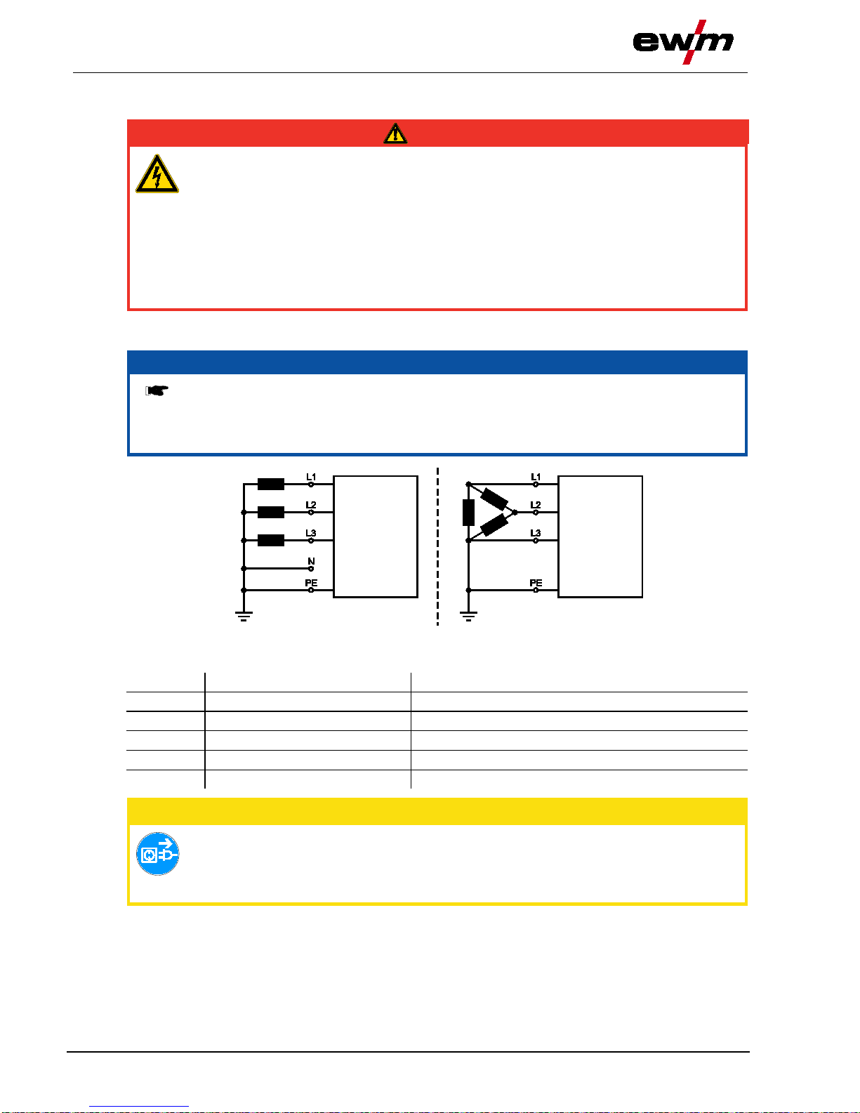
5.6.1 Mains configur at ion
NOTE
The machine may be connected to:
• a three-phase system with four conductors and an earthed neutral conductor
• a three-phase system with three conductors of which any one can be earthed,
e.g. the outer conductor
Figure 5-5
Legend
Item
Designation
Colour code
L1
Outer conductor 1
brown
L2
Outer conductor 2
black
L3
Outer conductor 3
grey
N
Neutral conductor
blue
PE
Protective conductor
green-yellow
CAUTION
Operating voltage - mains voltage!
The operating voltage shown on the rating plate must be consistent with the mains
voltage, in order to avoid damage to the machine!
• For mains fuse protection, please refer to the “Technical data” chapter!
• Insert mains plug of the switched-off machi ne i nto the appropriate socket.

Design an
d function
Shielding gas supply (shielding gas cylinder for welding machine)
099-005266-EW501
07.05.2014
29
5.7 Shielding gas supply (shielding gas cylinder for welding machine)
5.7.1 Connection
WARNING
Incorrect handling of shielding gas cylinders!
Incorrect handling of shielding gas cylinders can result in serious and even fatal injury.
• Observe the instructions from the gas manufacturer and in any relevant regulations
concerning the use of compressed air!
• Place shielding gas cylinders in the holders provi ded for them and secure with fixing
devices.
• Avoid heating the shielding gas cylinder!
CAUTION
Faults in the shielding gas supply.
An unhindered shielding gas supply from the shielding gas cylinder to the welding
torch is a fundamental requirement for optimum welding results. In addition, a blocked
shielding gas supply may result in the welding torch being destroyed.
• Always re-fit the yellow protective cap when not using the shielding gas connection.
• All shielding gas connections must be gas tight.
NOTE
Before connecting the pressure regulator to the gas cylinder, open the cylinder valve
briefly to expel any dirt.
Figure 5-6
Item
Symbol
Description 0
1
Pressure regulator
2
Shielding gas cylinder
3
Output side of the pressure regulator
4
Cylinder valve
• Place the shielding gas cylinder into the relev ant cylinder bracket.
• Secure the shielding gas cylinder using a securing chain.
• Tighten the pressure regulator screw connection on the gas bottle valve to be gas-tight.
• Tighten gas hose on pressure regulator to be gas tight.
• Fasten the gas hose to the shielding gas connecting nipple at the back of the machine using the crown
nut.

Design and function
Shielding gas supp
ly (shielding gas cylinder for welding machine)
30
099-005266-EW501
07.05.2014
5.7.2 Gas test, rinse hose package
• Slowly open the gas cylinder valve.
• Open the pressure reducer.
• Switch on the power source at the main switch.
• Trigger gas test function on the machine cont rol by pressing the button briefly.
• Set the relevant gas quantity for the applicat i on on the pressure reducer.
Operating
element
Action Result
Select gas test, rinse hose package.
Shielding gas flows for around 25 seconds or until the button is pressed
again. Repeat rinsing process several times.
5.7.3 Setting the shieldi ng gas quanti t y
Welding process
Recommended shielding gas quantity
MAG welding
Wire diameter x 11.5 = l/min
MIG brazing
Wire diameter x 11.5 = l/min
MIG welding (aluminium)
Wire diameter x 13.5 = l/min (100 % argon)
TIG
Gas nozzle diameter in mm corresponds to l/min gas t hroughput
Helium-rich gas mixtures require a higher gas volume!
The table below can be used to correct the gas volum e calculated where necessary:
Shielding gas
Factor
75% Ar/25% He
1.14
50% Ar/50% He
1.35
25% Ar/75% He
1.75
100% He
3.16
NOTE
Incorrect shielding gas setting!
If the shielding gas setting is too low or too high, this can introduce air to the weld pool
and may cause pores to form.
• Adjust the shielding gas quantity to suit the wel di ng task!

Design and function
MIG/MAG welding
099-005266-EW501
07.05.2014
31
5.8 MIG/MAG welding
5.8.1 Welding torch and workpiece l ine connec tion
NOTE
Fault with the wire guide!
On delivery, the central connector is fitted with a capillary tube for welding torches with
spiral guides. Conversion is necessary if a welding torch with a plastic core is used!
Welding torch with plastic core:
• use with guide tube!
Welding torch with spiral guide:
• use with capillary tube!
For connection, observe the operating instructions for the welding torch.
Depending on the wire electrode diameter or ty pe, either a steel liner or plastic liner with the
correct inner diameter must be inserted in the torch!
Recommendation:
• Use a steel liner when welding hard, unalloyed wire electrodes (steel).
• Use a chrome nickel liner when welding hard, high-alloy wire electrodes (CrNi).
• Use a plastic core to weld or braze soft wire el ectrodes, high-alloy wire electrodes or aluminium
materials.
Preparation for connecting welding torches with a spiral guide:
• Check that the capillary tube is correctly positioned in relation to the central connector!
Preparation for connecting welding torches with a plastic core:
• Push forward the capillary tube on the wire feed side in the direction of the central connector and
remove it there.
• Slide plastic core guide tube off the central connector.
• Carefully insert the central plug for the welding torch, with the still oversized plastic liner, into the
central connector and screw together with crown nut .
• Use a suitable tool to cut off the plastic liner just before the wire feed roller, making sure not to pinch it.
• Unfasten and remove the central plug on the welding torch.
• Cleanly remove the burr from the separated end of the plastic core!

Design and function
MIG/MAG welding
32
099-005266-EW501
07.05.2014
5.8.1.1 MIG/MAG standard welding
NOTE
Choose welding current connection socket according to the signal light for the polarity
setting!
• Select JOB
(see chapter “Function description, selecting M IG/MAG or TIG welding tasks”)
• Polarity selection “+” or polarity selection “-” signal lights show the polarity setting.
Figure 5-7
Item
Symbol
Description 0
1
Welding torch
2
Welding torch connection (Euro or Dinse torch connector)
Welding current, shielding gas and torch trigge r integrated
3
Workpiece
4
"-" welding current connection socket
• MIG/MAG welding:
Workpiece connection
5
Polarity selector plug, welding current cable
Internal welding current cable for central connecti on/welding torch.
• Connection socket for “+” welding current
• Insert the central plug for the welding t orch into the central connector and screw toget her with crown
nut.
• Insert the plug of the workpiece lead in the respective welding current connection socket and loc k i n
place by turning to the right.
• Insert the polarity selection plug in the respe ct i ve welding current connection socket and lock in pl ace
by turning to the right.

Design and function
MIG/MAG welding
099-005266-EW501
07.05.2014
33
5.8.1.2 MIG/MAG cored wire welding
NOTE
Choose welding current connection socket according to the signal light for the polarity
setting!
• Select JOB
(see chapter “Function description, selecting M IG/MAG or TIG welding tasks”)
• Polarity selection “+” or polarity selection “-” signal l i ghts show the polarity setting.
Figure 5-8
Item
Symbol
Description 0
1
Welding torch
2
Welding torch connection (Euro or Dinse torch connector)
Welding current, shielding gas and torch trigger i ntegrated
3
Workpiece
4
Connection socket, "+" welding current
• MIG/MAG cored wire welding:
Workpiece connection
5
Polarity selector plug, welding current cable
Internal welding current cable for central connecti on/welding torch.
• Connection socket for “-” welding current
• Insert the central plug for the welding torch into the central connector and screw together with crown
nut.
• Insert the plug of the workpiece lead in the res pective welding current connection socket and lock in
place by turning to the right.
• Insert the polarity selection plug in the respe ct i ve welding current connection socket and lock in pl ace
by turning to the right.

Design and function
MIG/MAG welding
34
099-005266-EW501
07.05.2014
5.8.2 Wire feed
5.8.2.1 Open the protective flap of the wire feeder
CAUTION
To perform the following steps, the protective flap of the wire feeder needs to be
opened. Make sure to close the protective flap again before starting to work.
• Unlock and open protective flap.
5.8.2.2 Inserting the wire spool
CAUTION
Risk of injury due to incorrectly secured wire spool.
If the wire spool is not secured properly, it may come loose from the wire spool holder
and fall to the ground, causing damage to the machine and injuries.
• Securely fasten the wire spool to the wire spool holder using the knurled nut.
• Before you start working, always check the wire spool is securely fastened.
Figure 5-9
Item
Symbol
Description 0
1
Carrier pin
For fixing the wire spool
2
Knurled nut
For fixing the wire spool
• Loosen knurled nut from spool holder.
• Fix welding wire reel onto the spool holder so that the carrier pin locks into the spool bore.
• Fasten wire spool using knurled nut.

Design and function
MIG/MAG welding
099-005266-EW501
07.05.2014
35
5.8.2.3 Changing the wire feed rollers
NOTE
Unsatisfactory welding results due to faulty wire feeding!
Wire feed rollers must be suitable for the diameter of the wire and the material.
• Check the roller label to verify that the rollers are suitable for the wire diameter.
Turn or change if necessary!
• use V-groove rollers with for steel wires and other hard wires,
• use U-groove rollers for aluminium wires and other soft, alloyed wires.
• Slide new drive rollers into place so that the diameter of the wire used is visible on the drive roller.
• Screw the drive rollers in place with knurled s cre ws.
Figure 5-10

Design and function
MIG/MAG welding
36
099-005266-EW501
07.05.2014
5.8.2.4 Inching the wire electrode
CAUTION
Risk of injury due to moving parts!
The wire feeders are equipped with moving parts, which can trap hands, hair, cl othing
or tools and thus injure persons!
• Do not reach into rotating or moving parts or drive com ponents!
• Keep casing covers or protective caps closed during operation!
Risk of injury due to welding wire escaping in an unpredictable manner!
Welding wire can be conveyed at very high speeds and, if conveyed incorrectly, may
escape in an uncontrolled manner and injure persons!
• Before mains connection, set up the complete wire guide system from the wire spool to the
welding torch!
• Remove the pressure rollers from the wire feede r i f no welding torch is fitted!
• Check wire guide at regular intervals!
• Keep all casing covers or protective caps closed during operation!
Risk of injury due to welding wire escaping from the welding torch!
The welding wire can escape from the welding torch at high speed and cause bodily
injury including injuries to the face and eyes!
• Never direct the welding torch towards your o wn body or towards other persons!
CAUTION
Extensive wear due to incorrect contact pressure!
Incorrect contact pressure will cause exten sive wear of the wire feed rollers!
• With the adjusting nuts of the pressure units set the contact pressure so that the wire
electrode is conveyed but will still slip through i f the wire spool jams.
• Set the contact pressure of the front rollers (i n wire feed direction) to a higher value!
NOTE
The inching speed is infinitely adjustable by simultaneously pressing the wire inching
push-button and turning the wire speed rotary knob. The left display shows the wire
feed speed selected, the right display shows the current motor current of the wire feed
mechanism.
Design and function
MIG/MAG welding
099-005266-EW501
07.05.2014
37
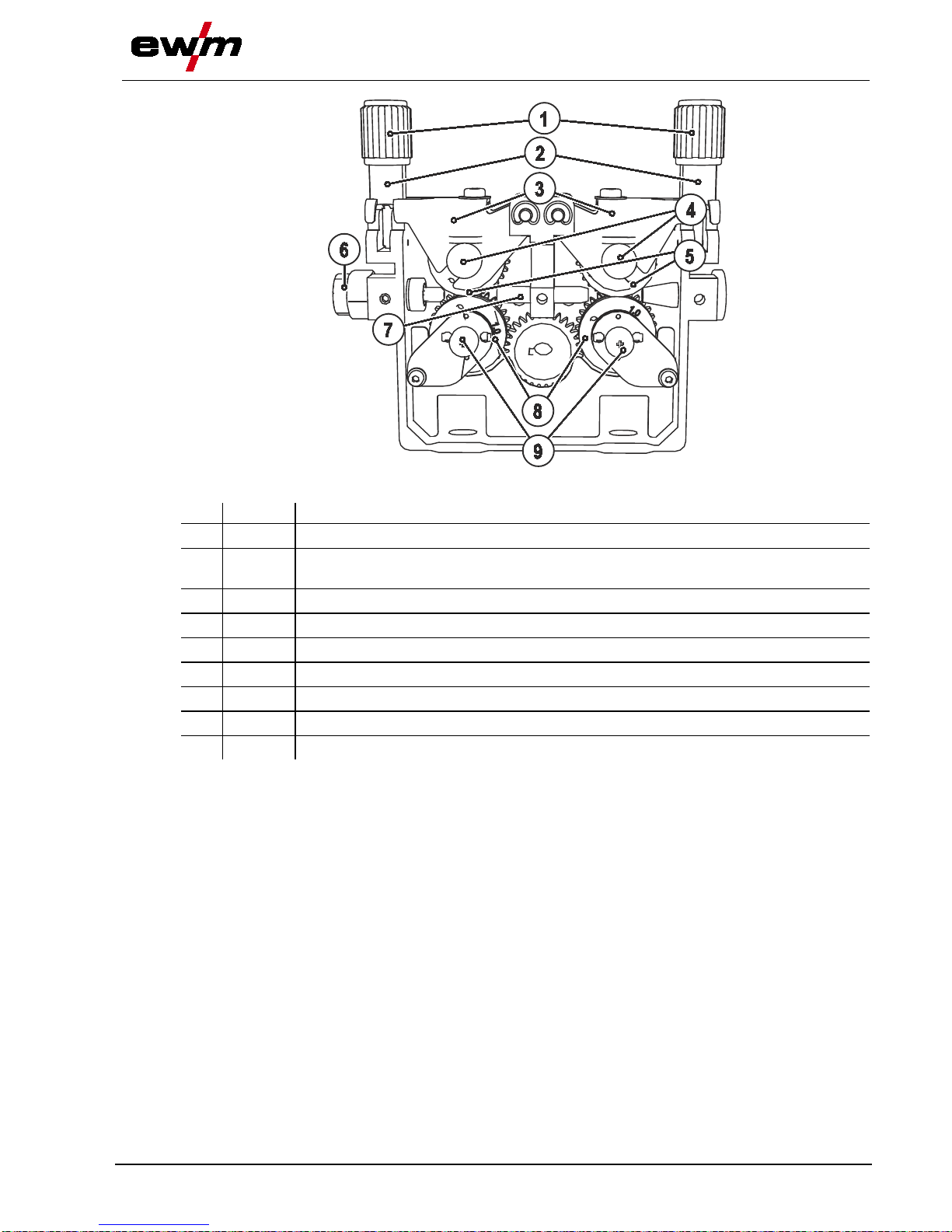
Figure 5-11
Item
Symbol
Description 0
1
Adjusting nut
2
Feed roll tensioner
Fixing the clamping unit and setting the pressure.
3
Clamping unit
4
Knurled screw
5
Pressure roller
6
Wire feed nipple
7
Guide tube
8
Drive roller
9
Axle
• Extend and lay out the torch hose package.
• Unfasten pressure units and fold out (clamping units and pressure rollers will automatically flip
upwards).
• Unwind welding wire carefully from the wire spool and insert through the wire inlet nipple over the
drive roller grooves and the guide pipe into the capillary tube and Teflon core using guide pipe.
• Press the clamping element with the pressure roller back downwards and fold the wire units back up
again (wire electrode should be in the groove on the drive roller).
• Set the contact pressure with the adjusti ng nuts of the pressure unit.
• Press the wire inching button until the wire electrode projects out of the welding torch.
Automatic inching stop
Touch the welding torch against the workpiece during i nching. Inching of the welding wire will stop as
soon it touches the workpiece.

Design and function
MIG/MAG welding
38
099-005266-EW501
07.05.2014
5.8.2.5 Spool brake setting
Figure 5-12
Item
Symbol
Description 0
1
Allen screw
Securing the wire spool retainer and adjustment of the spool brake
• Tighten the Allen screw (8 mm) in the clockwise direction to increase the braking effect.
NOTE
Tighten the spool brake until the wire spool no longer t urns when the wire feed motor
stops but
without it jamming during operation!
5.8.3 Definition of MIG/MAG welding tasks
This machine range features simple operation wit h a very wide range of functions.
• JOBs (welding tasks consisting of welding process, type of material, wire diameter and type of
shielding gas) are pre-defined for all common welding tasks.
• Simple JOB selection from a list of pre-defined J OBs (sticker on the machine).
• The required process parameters are calculated by the system depending on the operating point
specified (single-dial operation via wire speed rotary dial).
• Conventional welding task definition using wire speed and welding voltage is also possible.
NOTE
The welding task definition described below applies when defining MIG/MAG and cored
wire welding tasks.
Pay attention to the signal light for the polarity setting!
It may be necessary to change the welding current polarity depending on the JOB
selected or the welding process.
• Reconnect the polarity selction plug if necessary.
5.8.4 Welding task selecti on
The settings for the respective welding paramet ers are specified by the different JOBs. The right JOB can
be determined quickly with the JOB list.
In the example, the following details are known:
• Welding process: MIG/MAG
• Type of material (filler wire): G3Si1
• Wire diameter: 0.8 mm
• Shielding gas type: 80-90% Ar
• Panel thickness: 2 mm

Design and function
MIG/MAG welding
099-005266-EW501
07.05.2014
39
5.8.4.1 JOB selection
C
Item.
Selection 0
1
Welding process
MIG/MAG (solid wire)
2
Material type
G3
Si1 (steel)
3
Shielding gas type
80-90% Ar
4
Wire diameter
0,8 mm
A
B
2 mm
Determine welding task (JOB)
Set JOB 6
Set operating point via panel
thickness
VOLT
AMP
Wire
Gas
Material
JOBLIST
DYN
m/min
AMP
0
1
1
2
2
3
3
4
4
5
5
t2
t1
M 1.81
S
2.0
JOB 6
VOLT
AMP
Wire
Gas
Material
JOBLIST
DYN
m/min
AMP
0
1
1
2
2
3
3
4
4
5
5
t2
t1
M 1.81
S
6
4
32
1
6
Figure 5-13

Design and function
MIG/MAG welding
40
099-005266-EW501
07.05.2014
• Select JOB (welding task) by means of t he JOB list.
The "JOB list" sticker is on the inside of the cover of the wire feed unit.
• Set the operating point by means of the panel thickness (see chapter "Setting the MIG/MAG operating
point).
It is only possible to change the JOB number when no welding current is flowing.
Operating
element
Action
Result
Display
1 x
Select JOB list
(LED is on)
Set JOB number.
Wait 3 s until the setting has been applied.
5.8.4.2 Operating mode
Operating
element
Action Result
n x
Selecting the operating mode
The LED indicates the selected operating mode.
Non-latched operation
Latched operation
Spots
Interval operation
5.8.4.3 Welding type (MIG/MAG standard/pulse arc welding)
Operating
element
Action Result Display
n x
Select welding type
The signal light indicates the selection.
Standard MIG/MAG welding
Pulse arc MIG/MAG welding
No change

Design and function
MIG/MAG welding
099-005266-EW501
07.05.2014
41
5.8.5 Welding data display
Diagram 5-14
The button for the welding parameter display m ode i s next to the display.
Each time the button is pressed the display change s t o the next parameter. After the last parameter is
reached the display continues with the first param eter.
The display shows:
• Nominal values (before welding)
• Actual values (during welding)
• Hold values (after welding)
Parameter
Nominal values
Actual values
Hold values
Welding current
Material thickness
Wire speed
Welding voltage
After welding you can change back to the nominal values
• by pressing the buttons or using the dials on the controls
• or by briefly pressing the torch trigger.
5.8.5.1 Power-saving mode
The power-saving function can be activated eit her by pressing the button for a longer time (see chapter
"Machine description – Short overview") or by sett i ng a parameter in the configuration menu (time-based
power-saving mode).
When power-
saving mode is activated, both machine displ ays show the horizontal digit in the
centre of the display only.
Pressing any operating element (e.g. tapping the tor ch trigger) deactivates power-saving mode and the
machine is ready for welding again.

Design and function
MIG/MAG welding
42
099-005266-EW501
07.05.2014
5.8.6 MIG/MAG operating point
5.8.6.1 Selecting the welding parameter display mode
The operating point (welding performance) can b e displayed or set as the welding current, material
thickness or wire speed.
Operating
element
Action
Result
n x
Switching the display between:
Welding current
Welding voltage (correction)
Material thickness
Wire speed
5.8.6.2 Operating point setting using material thickness
The process of setting the operating point by means of the panel thickness parameter is described as an
example below.
Operating
element
Action Result Display
Increase or reduce welding performance via the
panel thickness parameter.
Display example: 2.0 mm
5.8.6.3 Arc length correction setting
Operating
element
Action
Result
“Arc length correction” setting
Setting range:
-5 V to +5 V
NOTE
The basic settings are now completed.
Other welding parameters have already been
set optimally in the factory; they can, howev er, be
modified to suit individual requirements.

Design and function
MIG/MAG welding
099-005266-EW501
07.05.2014
43
5.8.7 Further welding parameters
NOTE
Validity of the settings.
Settings for
• Spot time,
• Pause time and
• Wire feed speed
apply for all JOBs.
• Choke effect/dynamics,
• Gas post-flow time,
• Gas pre-flow time and
• Wire burn-back correction
are saved separately for each JOB.
Changes are stored permanently in the JOB that is currently selected.
Resetting to factory configuration, see chapter “Resetting the controls (Reset all)”
5.8.7.1 Choke effect / dynamics
Operating
element
Action
Result
Display
n x
Selecting the parameter to be set
The LED indicates the parameter selected.
Parameter value set
Choke effect/dynamics
Gas post-flow time
Spot time
Pause time (interval operation)
Set choke effect/dynamics.
Setting range:
40: Arc ha rd and narrow, deeper
fusion penetration.
-40: Arc soft and wide.
5.8.7.2 Gas post-flow time
Operating
element
Action Result Display
n x
Selecting the parameter to be set
The LED indicates the parameter selected.
Parameter value set
Choke effect/dynamics
Gas post-flow time
Spot time
Pause time (interval operation)
Adjusting the gas post-flow time.
Setting range:
0.0 s to 20.0 s in increments of 0.1 s

Design and function
MIG/MAG welding
44
099-005266-EW501
07.05.2014
5.8.7.3 Spot time
NOTE
Select the respective operating mode before setting the spot or pause tim e.
Operating
element
Action
Result
Display
n x
Selecting the parameter to be set
The LED indicates the parameter selected.
Parameter value set
Choke effect/dynamics
Gas post-flow time
Spot time
Pause time (interval operation)
Setting the stop time.
Setting range:
0.1 s to 20.0 s in increments of 0.1 s
5.8.7.4 Pause time (interval operation)
Operating
element
Action Result Display
n x
Selecting the parameter to be set
The LED indicates the parameter selected.
Parameter value set
Choke effect/dynamics
Gas post-flow time
Spot time
Pause time (interval operation)
Setting the pause time.
Setting range:
0.1 s to 20.0 s in increments of 0.1 s

Design and function
MIG/MAG welding
099-005266-EW501
07.05.2014
45
5.8.7.5 Burn-back
• Preselection: Select a MIG/MAG JOB (see chapter “Selecting MIG/MAG welding tasks”).
ENTER
3 s
EXIT
3 s
NAVIGATION
m/min
AMP
DYN
t2
t1
DYN
t2
t1
Figure 5-15
Display
Setting/selection
Burn-back correction
0 to 499 of the burn back time specified in the JOB
5.8.7.6 gas pre-flow time
• Preselection: Select a MIG/MAG JOB (see chapter “Selecting MIG/MAG welding tasks”).
ENTER
3 s
EXIT
3 s
NAVIGATION
m/min
AMP
DYN
t2
t1
DYN
t2
t1
Figure 5-16
Display
Setting/selection
Gas pre-flow time
0.0 s to 20.0 s (0.1 s increments)
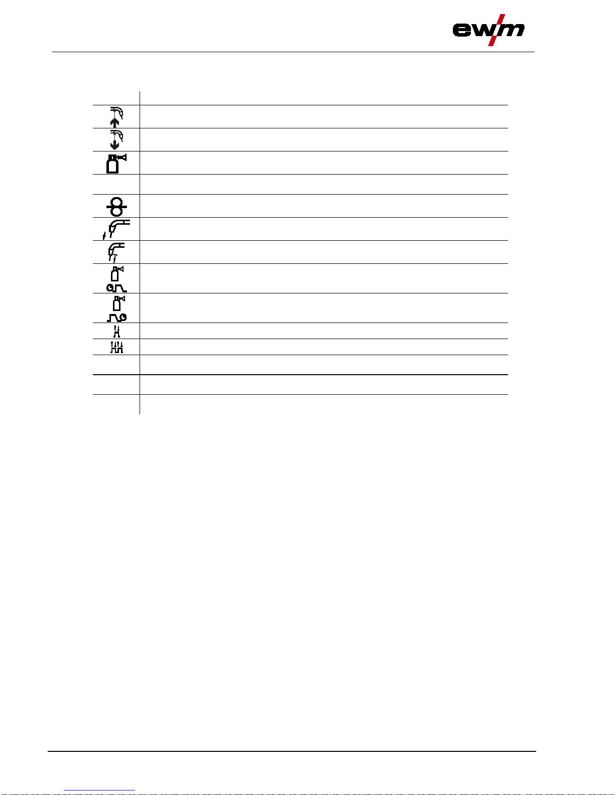
Design and function
MIG/MAG welding
46
099-005266-EW501
07.05.2014
5.8.8 MIG/MAG functional sequences / operating modes
5.8.9 Explanation of si gns and functions
Symbol
Meaning
Press torch trigger
Release torch trigger
Shielding gas flowing
I
Welding output
Wire electrode is being conveyed
Wire creep
Wire burn-back
Gas pre-flows
Gas post-flows
Non-latched
Latched
t
Time
t1
Spot time
t2
Pause time
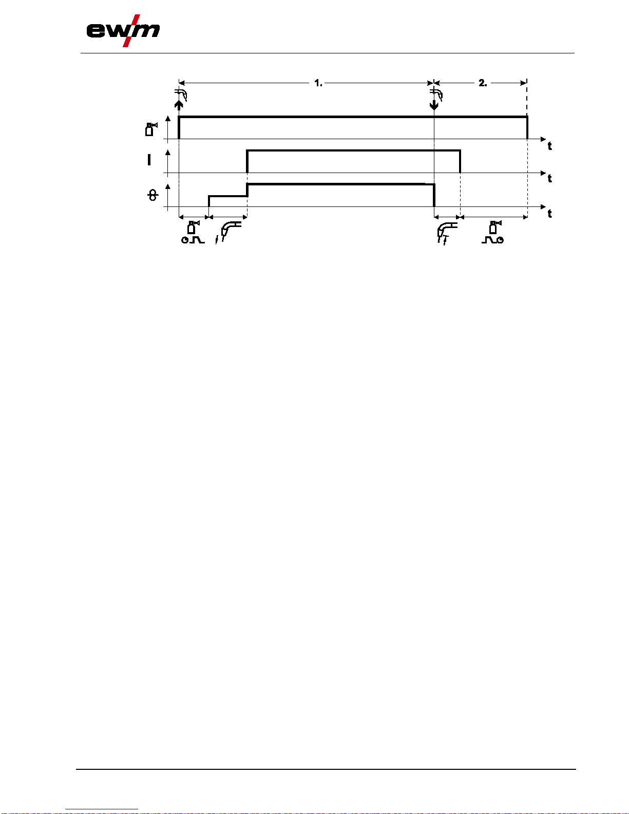
Design and function
MIG/MAG welding
099-005266-EW501
07.05.2014
47
Non-latched mode
Figure 5-17
Step 1
• Press and hold torch trigger.
• Shielding gas is expelled (gas pre-flows).
• Wire feed motor runs at “creep speed”.
• Arc ignites after the wire electrode makes contact with the workpiece; welding current flows.
• Change over to pre-selected wire speed.
Step 2
• Release torch trigger.
• WF motor stops.
• Arc is extinguished after the preselected wire burn-back time expires.
• Gas post-flow time elapses.

Design and function
MIG/MAG welding
48
099-005266-EW501
07.05.2014
Latched mode
Figure 5-18
1. cycle
• Press and hold torch trigger
• Shielding gas is expelled (gas pre-flows)
• Wire feed motor runs at “creep speed”
• Arc ignites when the wire electrode make s contact with the workpiece
Welding current flows
• Wire feed speed increases to the set nominal value
2. cycle
• Release torch trigger (no effect)
3. cycle
• Press torch trigger (no effect)
4. cycle
• Release torch trigger
• Wire feed motor stops
• Arc is extinguished after the pre-selecte d wire burn-back time elapses
• Gas post-flow time elapses

Design and function
MIG/MAG welding
099-005266-EW501
07.05.2014
49
Spot welding
Figure 5-19
Start
• Press and hold torch trigger.
• Shielding gas is expelled (gas pre-flows).
• Arc ignites after the wire electrode makes contact with the workpiece at creep speed.
• Welding current flows.
• Wire feed speed increases to the set nomi nal value.
• The wire feed stop welding after the spot t i m e el apses.
• Arc is extinguished after the wire burn-back tim e elapses.
• Gas post-flow time elapses.
Premature termination
• Release torch trigger.

Design and function
MIG/MAG welding
50
099-005266-EW501
07.05.2014
Interval
Figure 5-20
Start
• Press and hold torch trigger.
• Shielding gas is expelled (gas pre-flows).
Sequence
• Arc ignites after the wire electrode makes contact with the workpiece at creep speed.
• Welding current flows.
• Wire feed speed increases to the set nominal value.
• The wire feed stops after the spot time elapses.
• Arc is extinguished after the wire burn-back tim e elapses.
• The process is repeated when the pause t i m e is over.
End
• Release torch trigger, wire feed stops, arc is extinguished, gas post-flow time elapses.
If the pause time is less than 3 s, wire creep only takes place in the first spot phase.
When the torch trigger is released, the welding process is also ended even before the spot time elapses.

Design and function
MIG/MAG welding
099-005266-EW501
07.05.2014
51
5.8.10 Conventi onal MIG/MAG Welding (GMAW non synergic)
• Select JOB 188
It is only possible to change the JOB number when no welding current is flowing.
Operating
element
Action
Result
Display
1 x
Select JOB list
(LED is on)
Set JOB number.
Wait 3 s until the setting has been applied.
5.8.10.1 Operating mode
Operating
element
Action
Result
n x
Selecting the operating mode
The LED indicates the selected operating mode.
Non-latched operation
Latched operation
Spots
Interval operation
5.8.11 Wel di ng data di spl ay
Diagram 5-21
The button for the welding parameter display m ode i s next to the display.
Each time the button is pressed the display change s t o the next parameter. After the last parameter is
reached the display continues with the first parameter.
The display shows:
• Nominal values (before welding)
• Actual values (during welding)
• Hold values (after welding)
Parameter
Nominal values
Actual values
Hold values
Welding current
Wire speed
Welding voltage
After welding you can change back to the nominal values
• by pressing the buttons or using the dials on the controls
• or by briefly pressing the torch trigger.

Design and function
MIG/MAG welding
52
099-005266-EW501
07.05.2014
5.8.11.1 Setting the operating point (welding output)
The operating point (welding performance) is set with the wire speed and the welding voltage.
Operating
element
Action
Result
n x
Switch the display between:
Welding current (only actual and hold values are displayed)
Welding voltage
Material thickness (will be skipped)
Wire speed
Settings are made using the "welding parameter s etting" and "arc length correction" rotary dials, which
are used here to set the wire speed and the welding volt age.
Operating
element
Action
Result
Increase or reduce welding performance via the wire speed parameter.
Operating
element
Action Result
Set the welding voltage
Setting range:
5 V to 35 V
NOTE
Automatic display mode
switching:
If the wire speed or the voltage is changed, the display will switch briefly to show the
respective parameter. This means that you don't have to change the display mode before
setting the parameter.
If the display mode is set to display the weld
ing current, it will always show "0" before weldi ng
begins. Actual values are shown during welding; these can be changed as necessary using the
"welding parameter setting" rotary dial.
5.8.12 MIG/MAG automatic cut-out
NOTE
The welding machine ends the ignition process or the welding process with an
• ignition fault (no welding current flows within 5 s after the start signal)
• arc interruption (arc is intrerupted for long er than 5 s)

Design and function
MMA welding
099-005266-EW501
07.05.2014
53
5.9 MMA welding
CAUTION
Risk of being crushed or burnt.
When replacing spent or new stick electrodes
• Switch off machine at the main switch
• Wear appropriate safety gloves
• Use insulated tongs to remove spent stick elect rodes or to move welded workpieces and
• Always put the electrode holder down on an insulated surface.
5.9.1 Connecting the electrode holder and workpiece lead
Figure 5-22
Item
Symbol
Description 0
1
Electrode holder
2
Workpiece
3
Connection socket for "+" welding current
Electrode holder or workpiece lead connection
4
Connection socket, “-” welding current
Electrode holder or workpiece lead connection
5
Polarity selector plug, welding current cable
• Connect to the park socket.
• Insert the polarity selection plug in the park socket and lock in place by turning to the right.
• Insert cable plug of the electrode holder into either the "+" or "-" welding current connection socket and
lock by turning to the right.
• Insert cable plug of the workpiece lead into either the "+" or "-" welding current connection socket and
lock by turning to the right.
NOTE
Polarity depends on the instructions from the electrode manufacturer given on the
electrode packaging.

Design and function
MMA welding
54
099-005266-EW501
07.05.2014
5.9.2 Welding task selecti on
C
Item
.
Selection 0
1
Welding process
MMA
A
B
Determine welding task (JOB)
Set JOB 128
Set welding current
JOB 128
VOLT
AMP
Wire
Gas
Material
JOBLIST
DYN
m/min
AMP
0
1
1
2
2
3
3
4
4
5
5
t2
t1
M 1.81
S
100
VOLT
AMP
Wire
Gas
Material
JOBLIST
DYN
m/min
AMP
0
1
1
2
2
3
3
4
4
5
5
t2
t1
M 1.81
S
128
1
Figure 5-23

Design and function
MMA welding
099-005266-EW501
07.05.2014
55
• Select MMA JOB 128.
It is only possible to change the JOB number when no welding current is flowing.
Operating
element
Action Result Display
1 x
Select JOB list
(LED is on)
Set JOB number.
Wait 3 s until the setting has been applied.
5.9.3 Welding current setting
Set the welding current with the rotary dial f or the welding parameter settings.
Operating
element
Action
Result
Display
Set welding current. current nominal
value
5.9.4 MMA welding data display
Diagram 5-24
The button for the welding parameter display m ode i s next to the display.
Each time the button is pressed it switches betwee n w elding current and welding voltage.
The display shows:
• Nominal values (before welding)
• Actual values (during welding)
• Hold values (after welding)
Parameter
Nominal values
Actual values
Hold values
Welding current
Welding voltage
The display switches back from hold values to a ct ual values for approximately 5 s after welding is
finished.
5.9.4.1 Power-saving mode
The power-saving function can be activated eit her by pressing the button for a longer time (see chapter
"Machine description – Short overview") or by sett i ng a parameter in the configuration menu (time-based
power-saving mode).
When power-
saving mode is activated, both machine displ ays show the horizontal digit in the
centre of the display only.
Pressing any operating element (e.g. tapping the tor ch trigger) deactivates power-saving mode and the
machine is ready for welding again.

De
sign and function
MMA welding
56
099-005266-EW501
07.05.2014
5.9.5 Arcforce
During the welding process, arcforce prevent s the electrode sticking in the weld pool with increases in
current. This makes it easier to weld large-drop melting electrode types at low current strengths with a
short arc in particular.
Operating
element
Action
Result
Display
1 x
Select DYN setting
(LED is on)
Parameter value
setting
Arc forcing setting for electrode types:
Setting range -40 to 40
Negative values:
Rutile
Values around zero:
Basic
Positive values:
Rutilecellulose
5.9.6 Hotstart
The hotstart device improves the ignition of t he st i ck electrodes using an increased ignition current.
a) = Hotstart time
b) = Hotstart current
I = Welding current
t = Time
Figure 5-25

Design and function
MMA welding
099-005266-EW501
07.05.2014
57
5.9.6.1 Hotstart settings
• Select MMA JOB 128. (see chapter “Selecting MMA welding tasks”)
ENTER
3 s
EXIT
3 s
NAVIGATION
m/min
AMP
DYN
t2
t1
DYN
t2
t1
Figure 5-26
Display
Setting/selection
Hotstart current
0% to 200% of the welding current (1% increments)
Hotstart time
0.0 s to 20.0 s (0.1 s increments)
5.9.7 Antistick
Anti-stick prevents the electrode from annealing.
If the electrode sticks in spite of the Arcforce device, the machine
automatically switches over to the minimum curre nt within about 1
second to prevent the electrode from overheating. Check the welding
current setting and correct according to the welding task!
Figure 5-27

Design and functio
n
TIG welding
58
099-005266-EW501
07.05.2014
5.10 TIG welding
5.10.1 Prepari ng the TIG welding torch
The TIG welding torch is to be equipped to suit the relevant welding task!
• Fit suitable tungsten electrodes and
• an appropriate shielding gas nozzle.
• Observe the operating instructions for t he TIG welding torch!
5.10.2 Wel di ng torch and workpiece line connection
Figure 5-28
Item
Symbol
Description 0
1
Welding torch
2
Welding torch connection (Euro or Dinse torch connector)
Welding current, shielding gas and torch trigger integrated
3
Workpiece
4
Connection socket, "+" welding current
• TIG welding:
Workpiece connection
5
Polarity selector plug, welding current cable
Internal welding current cable for central connecti on/welding torch.
• Connection socket for “-” welding current
• Insert the central plug for the welding t orch into the central connector and screw toget her with crown
nut.
• Insert the polarity selection plug into the "-" welding current connection socket and lock in place by
turning to the right.
• Insert the plug of the workpiece lead into the " +" welding current connection socket and lock in place
by turning to the right.

Design and function
TIG welding
099-005266-EW501
07.05.2014
59
5.10.3 Welding task selection
C
Item.
Selection 0
1
Welding process
TIG
A
B
Determine welding task (JOB)
Set JOB 127
Set welding current
JOB 127
VOLT
AMP
Wire
Gas
Material
JOBLIST
DYN
m/min
AMP
0
1
1
2
2
3
3
4
4
5
5
t2
t1
M 1.81
S
127
VOLT
AMP
Wire
Gas
Material
JOBLIST
DYN
m/min
AMP
0
1
1
2
2
3
3
4
4
5
5
t2
t1
M 1.81
S
100
1
Figure 5-29

Design and function
TIG welding
60
099-005266-EW501
07.05.2014
• Select TIG JOB 127.
It is only possible to change the JOB number when no welding current is flowing.
Operating
element
Action Result Display
1 x
Select JOB list
(LED is on)
Set JOB number.
Wait 3 s until the setting has been applied.
5.10.4 Welding current setting
Set the welding current with the rotary dial f or the welding parameter settings.
Operating
element
Action Result Display
Set welding current. current nominal
value
5.10.5 Adjusting the gas post-flow time
Operating
element
Action
Result
Display
1 x
Select setting for gas post-flow time
(LED is on
parameter value
setting
Setting the gas post-flow time
Setting range:
0.0 s to 20.0 s
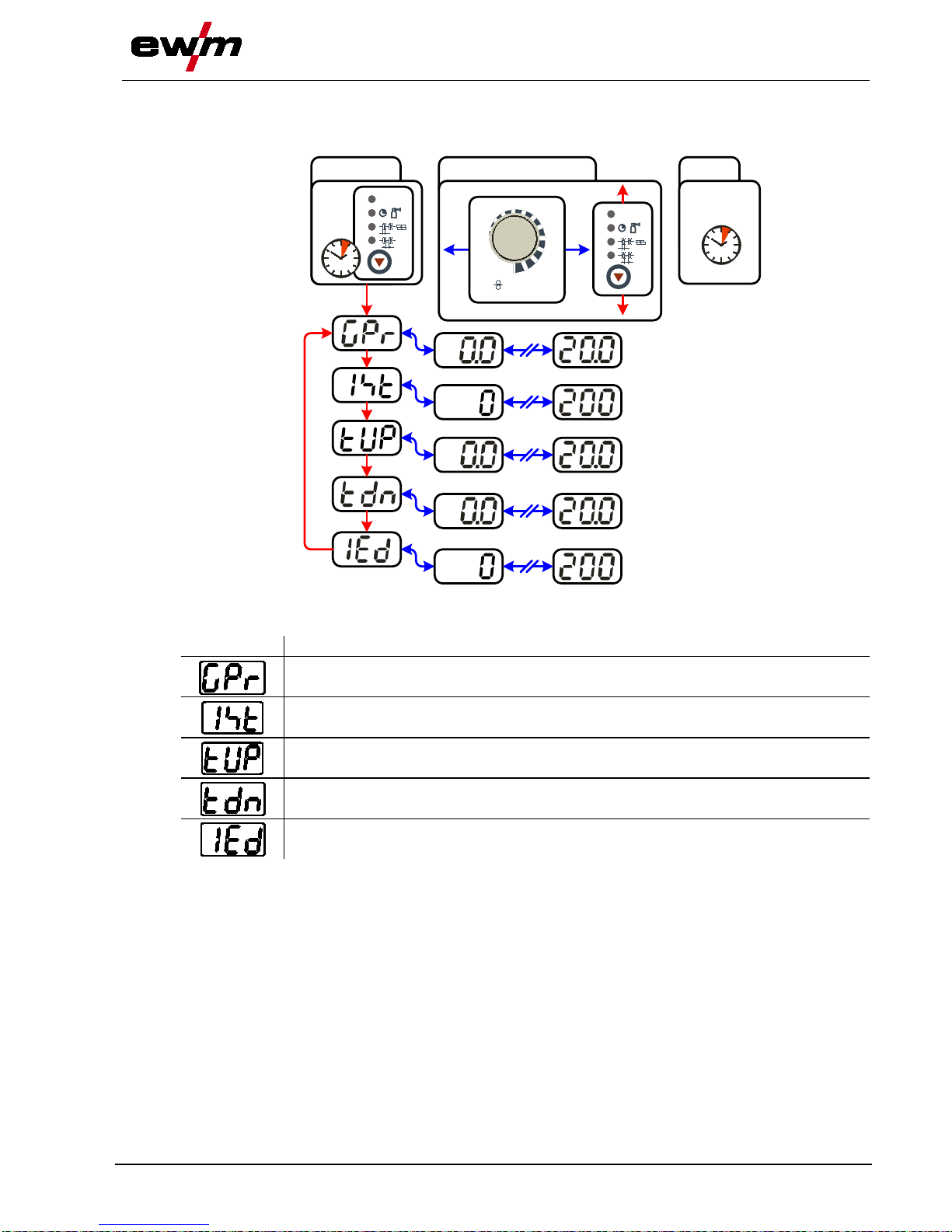
Design and function
TIG welding
099-005266-EW501
07.05.2014
61
5.10.6 Further welding parameters
• Preselection: Select TIG JOB 127. (see chapter “Selecting TIG welding tasks”)
ENTER
3 s
EXIT
3 s
NAVIGATION
m/min
AMP
DYN
t2
t1
DYN
t2
t1
Figure 5-30
Display
Setting/selection
Gas pre-flow time
0.0 s to 20.0 s (0.1 s increments)
Ignition current
0% to 200% of the welding current (1% increment s)
Upslope time
0.0 s to 20.0 s (0.1 s increments)
Downslope time
0.0 s to 20.0 s (0.1 s increments)
End current
0% to 200% of the welding current (1% increments)

Design and function
TIG welding
62
099-005266-EW501
07.05.2014
5.10.7 TIG welding data display
Diagram 5-31
The button for the welding parameter display m ode i s next to the display.
Each time the button is pressed it switches betwee n welding current and welding voltage.
The display shows:
• Nominal values (before welding)
• Actual values (during welding)
• Hold values (after welding)
Parameter
Nominal values
Actual values
Hold values
Welding current
Welding voltage
The display switches back from hold values to a ct ual values for approximately 5 s after welding is
finished.
5.10.7.1 Power-saving mode
The power-saving function can be activated either by pressing the button for a longer time (see chapter
"Machine description – Short overview") or by sett i ng a parameter in the configuration menu (time-based
power-saving mode).
When power-saving mode is activated, both machine displays show the horizontal digit in the
centre of the display only.
Pressing any operating element (e.g. tapping the tor ch trigger) deactivates power-saving mode and the
machine is ready for welding again.
5.10.8 TIG arc ignition
5.10.8.1 Liftarc ignition
Figure 5-32
The arc is ignited on contact with the workpiece:
a) Carefully place the torch gas nozzle and tungsten electrode tip onto the workpiece and press the torch
trigger (liftarc current flowing, regardless of the main current set).
b) Incline the torch over the torch gas nozzle to produce a gap of approx. 2-3 mm bet ween the electrode
tip and the workpiece. The arc ignites and the welding current is increased, depending on the
operating mode set, to the ignition or main curre nt set.
c) Lift off the torch and swivel to the normal position.
Ending the welding process: Release or press the torch trigger depending on the operating mode
selected.

Design and function
TIG welding
099-005266-EW501
07.05.2014
63
5.10.9 Functi on sequences/operating modes
5.10.9.1 Legend
Symbol
Meaning
Press torch trigger
Release torch trigger
I
Welding current
Gas pre-flows
Gas post-flows
Non-latched
Latched
t
Time
t
Up
Upslope time
t
Down
Downslope time
I
start
Ignition current
I
end
End-crater current
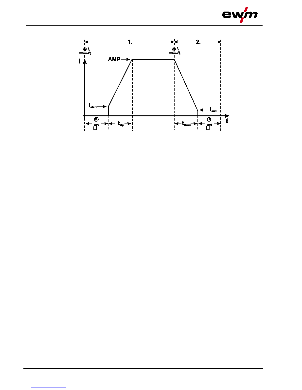
Design and function
TIG welding
64
099-005266-EW501
07.05.2014
Non-latched mode
Figure 5-33
1st cycle
• Press and hold torch trigger.
• Shielding gas is expelled (gas pre-flows).
The arc is ignited using liftarc.
• The welding current flows with the value set for the starting current I
start
.
• Welding current increases to the main current in the set upslope time.
2nd cycle
• Release torch trigger.
• The main current falls in the set downslope time to the end-crater current I
end
.
If the torch trigger is pressed again during the downslope time,
the welding current returns to the set main current!
• The main current reaches the end-crater current I
end
, the arc extinguishes.
• Gas post-flow time elapses.

Design and function
TIG welding
099-005266-EW501
07.05.2014
65
Latched mode
Figure 5-34
1st cycle
• Press and hold torch trigger.
• Shielding gas is expelled (gas pre-flows).
The arc is ignited using liftarc.
• The welding current flows with the value set for the starting current I
start
.
2nd cycle
• Release torch trigger.
• Welding current increases to the main current in the set upslope time.
3rd cycle
• Press and hold torch trigger.
• The main current falls in the set downslope ti m e to the end-crater current I
end
.
4th cycle
• Release torch trigger, arc is extinguished.
• Gas post-flow time elapses.
The welding process is terminated immediately if the torch trigger is released during the
downslope time.
The welding current drops to zero and the gas post-flow ti m e begins.
5.10.10 TIG automatic cut-out
NOTE
The welding machine ends the ignition process or the welding process with an
• Ignition fault (no welding current flows within 3 s aft er the start signal).
• Arc interruption (arc is intrerupted for longer t han 3 s).

Design and function
Machine configuration menu
66
099-005266-EW501
07.05.2014
5.11 Machine configuration menu
5.11.1 Select i ng, changing and saving parameters
NOTE
ENTER (Enter the menu)
• Switch off the machine at the main switch.
• Press and hold the "sequence parameter" push-button and switch the machine on again at
the same time.
NAVIGATION (Navigate the menu)
• Select parameters by pressing the "sequence parameter" push-button.
• Set or change the parameters by turning the " weldi ng parameter setting" rotary knob.
EXIT (Exit the menu)
• Press the "gas test/flushing" push-button (swit ch m achine off and on again).
ENTER
EXIT
+
NAVIGATION
l
0
DYN
t2
t1
DYN
t2
t1
m/min
AMP
Figure 5-35
Display
Setting/selection
Lead resistance 1
Lead resistance for the first welding circuit 0 mΩ–60 mΩ (8 mΩ ex works).
Only qualified service personnel may change the parameters!
Time-based power-saving mode
• 5 min.–60 min. = Time to activation of power-saving m ode i n case of inactivity.
• off = inactivated

Design and function
Machine configuration menu
099-005266-EW501
07.05.2014
67
5.11.2 Mat ching the cable resistance
The resistance value of cables can either be set directly or it can be matched using the power source.
The factory setting of the power sources is 8 m-ohm. Thi s v al ue correponds to a 5 m earth cable, a 1.5 m
intermediate hose package and a 3 m water-cooled welding torch. With other hose package lengths, it is
necessary to carry out a +/- voltage correction to optimise welding properties. The voltage correction
value can be set close to zero by means of re-matching t he cable resistance. It is recommended to match
the electric cable resistance after replacing acce ss ories such as torches or intermediate hose packages.
In case a second wire feeder is used the (rL2) parameter has to be adjusted. For all other configurations it
is sufficient to match the (rL1) parameter.
2
3
4
1
+
l
0
50mm
l
0
B
A
DYN
t2
t1
Figure 5-36

Design and function
Mach
ine configuration menu
68
099-005266-EW501
07.05.2014
1 Preparation
• Switch off the welding machine.
• Unscrew the gas nozzle of the welding torch.
• Cut off the welding wire to be flush with the cont act tip.
• Retract the welding wire a bit (approx. 50 mm) on t he wire feeder. Now there should be no more
welding wire in the contact tip.
2 Configuration
• Press the "sequence parameter" push-button while simultaneously switching on the welding machi ne.
Release the "sequence parameter" push-button.
• The desired parameter can now be select ed using the "sequence parameter" push-button. Parameter
rL1 must be balanced for all machine combinations. In case of welding systems with a second power
circuit – if two wire feeders are to be operated from a single power source, for example – a second
balancing with parameter rL2 must be performed.
3 Balancing/measurement
• Applying slight pressure, put the welding torch in place with the contact tip on a clean, purged location
on the workpiece and then press the torch trigger for approx. 2 seconds. Short-circuit current flows
briefly, which is used to determine and display the cable resistance. The value can be between 0 mΩ
and 40 mΩ. The new value is immediately saved without requiring any further confirmation. If no value
is shown in the right display, then the measurement failed. The measurement must be repeated.
4 Restoring welding standby mode
• Switch off the welding machine.
• Screw the gas nozzle onto the welding torch.
• Switch on the welding machine
• Insert the welding wire.

Maintenance, care and disposal
General
099-005266-EW501
07.05.2014
69
6 Maintenance, care and disposal
DANGER
Do not carry out any unauthorised repairs or modifications!
To avoid injury and equipment damage, the unit must only be repaired or modified by
specialist, skilled persons!
The warranty becomes null and void in the event of unauthorised interference.
• Appoint only skilled persons for repair work (trained service personnel)!
Risk of injury from electric shock!
Cleaning machines that are not disconnected from the mains can lead to serious
injuries!
• Disconnect the machine completely from the mains.
• Remove the mains plug!
• Wait for 4 minutes until the capacitors have di scharged!
6.1 General
When used in the specified environmental conditions and under normal operating conditions, t hi s
machine is largely maintenance-free and requires a minimum of care.
There are some points, which should be observed, to guarantee fault-free operation of your welding
machine. Among these are regular cleaning and checking as described below, depending on the pollution
level of the environment and the length of ti m e the unit is in use.
6.2 Maintenance work, intervals
6.2.1 Daily maintenance tasks
• Clean the wire feed rollers on a regular basis (depending on the degree of soiling).
6.2.1.1 Visual inspection
• Mains supply lead and its strain relief
• Gas tubes and their switching equipment (solenoid valve)
• Other, general condition
6.2.1.2 Functional test
• Check correct mounting of the wire spool.
• Welding current cables (check that the y are fitted correctly and secured)
• Gas cylinder securing elements
• Operating, message, safety and adju st m ent devices (Functional test)
6.2.2 Monthly maintenance tasks
6.2.2.1 Visual inspection
• Casing damage (front, rear and side walls)
• Wheels and their securing elements
• Transport elements (strap, lifting lugs, handle)
6.2.2.2 Functional test
• Selector switches, command devices, em ergency stop devices, voltage reducing devices, m essage
and control lamps
• Check that the wire guide elements (inlet ni pple, wire guide tube) are fitted securely.

Maintenance, care and disposal
Maintenance work
70
099-005266-EW501
07.05.2014
6.2.3 Annual test (inspection and testing during operation)
NOTE
The welding machine may only be tested by competent, capable personsl.
A capable person is one who, because of his training, knowledge and experience, is
able to recognise the dangers that can occur while testing welding power sources as
well as possible subsequent damage and who is able to implement the required safety
procedures.
For further information, please see the accompanying supplementary sheets "Machine
and Company Data, Maintenance and Testing, Warranty"!
A periodic test according to IEC 60974-4 "Periodic in spection and test" has to be carried out. In addition
to the regulations on testing given here, the relevant local laws and regulations must also be observed.
6.3 Maintenance work
Repair and maintenance work may only be perfo rmed by qualified authorised personnel; otherwise t he
right to claim under warranty is void. In all servic e m atters, always consult the dealer who supplied t he
machine. Return deliveries of defective equipment subject to warranty may only be made through y our
dealer. When replacing parts, use only original spare parts. When ordering spare parts, please quote the
machine type, serial number and item number of the machine, as well as the type designation and item
number of the spare part.

Maintenance, care and disposal
Disposing of equipment
099-005266-EW501
07.05.2014
71
6.4 Disposing of equipment
NOTE
Proper disposal!
The machine contains valuable raw materials, which should be recycled, and
electronic components, which must be disposed of.
• Do not dispose of in household waste!
• Observe the local regulations regarding disposal!
6.4.1 Manufacturer's declaration to the end user
• According to European provisions (guideli ne 2002/96/EG of the European Parliament and the Council
of January, 27th 2003), used electric and electroni c equipment may no longer be placed in unsorted
municipal waste. It must be collected separately. The symbol depicting a waste container on wheels
indicates that the equipment must be collected separately.
This machine is to be placed for disposal or recycling in the waste separation systems provided for
this purpose.
• According to German law (law governing t he di st ri bution, taking back and environmentally cor rect
disposal of electric and electronic equipment (E l ektroG) from 16.03.2005), used machines ar e to be
placed in a collection system separate from unsorted municipal waste. The public waste management
utilities (communities) have created collecti on points at which used equipment from private
households can be disposed of free of charge.
• Information about giving back used equipm ent or about collections can be obtained from the
respective municipal administration office.
• EWM participates in an approved waste disposal and recycling system and is registered in the Used
Electrical Equipment Register (EAR) under number WEEE DE 57686922.
• In addition to this, returns are also possible t hroughout Europe via EWM sales partners.
6.5 Meeting the requirements of RoHS
We, EWM AG Mündersbach, hereby confirm that all products supplied by us which are affected by the
RoHS Directive, meet the requirements of the RoHS (Directive 2002/95/EC).

Rectifying faults
Checklist for rectifying faults
72
099-005266-EW501
07.05.2014
7 Rectifying faults
All products are subject to rigorous production checks and final checks. If, despite this, something fails to
work at any time, please check the product using the following flowchart. If none of the fault rectificat i on
procedures described leads to the correct functioning of the product, please inform your authorise d
dealer.
7.1 Checklist for rectifying faults
NOTE
The correct machine equipment for the material and process gas in use is a
fundamental requirement for perfect operation!
Legend
Symbol
Description
Fault/Cause
Remedy
Wire feed problems
Contact tip blocked
Clean, spray with anti-spatter spray and replace if necessary
Setting the spool brake (see "Setting the spool brake" chapter)
Check settings and correct if necessary
Setting pressure units (see "Inching wire electrodes" chapter)
Check settings and correct if necessary
Worn wire rolls
Check and replace if necessary
Wire feed motor without supply voltage (automatic cutout triggered by overloading)
Reset triggered fuse (rear of the power source) by pressing the key button
Kinked hose packages
Extend and lay out the torch hose package
Wire guide core or spiral is dirty or worn
Clean core or spiral; replace kinked or worn cores
Functional errors
Machine control without displaying the signal lights after switching on
Phase failure > check mains connection (fuses)
No welding performance
Phase failure > check mains connection (fuses)
Various parameters cannot be set
Entry level is blocked, disable access lock (see c hapter entitled "Lock welding parameters
against unauthorised access")
Connection problems
Make control lead connections and check that they are fitt ed corr ectly.
Loose welding current connections
Tighten power connections on the torch and/or on the workpiece
Tighten contact tip correctly
Mains fuse triggers
Unsuitable mains fuse
Set up the mains fuse according to the "Technical data" chapter.

Rectifying faults
Error messages (power source)
099-005266-EW501
07.05.2014
73
7.2 Error messages (power source)
NOTE
A welding machine error is indicated by an error code being displayed (see table) on the
display on the machine control.
In the event of a machine error, the power unit is shut down.
The display of possible error numbers depends on the machine version
(interfaces/functions).
• Document machine errors and inform servi ce staff as necessary.
• If multiple errors occur, these are displa yed in succession.
Error
Category
Possible cause Remedy
a)
b)
c)
Error 1
(Ov.Vol)
- - x Mains overvoltage Check the mains voltages and compare with
the connection voltages of the welding
machine
Error 2
(Un.Vol)
- - x
Mains undervoltage
Error 3
(Temp)
x - - Welding machine excess
temperature
Allow the machine to cool down (mains
switch to "1")
Error 4
(Water)
xx x - Low coolant level Top off the coolant
Leak in the coolant circuit >
rectify the leak and top off the coolant
Coolant pump is not working > check excess
current trigger on air cooling unit
Error 5
(Wi.Spe)
x - - Wire feeder, speedometer
error
Check the wire feeder
speedometer is not issuing a signal,
M3.00 defective > inform Service
Error 6
(gas)
x - -
Shielding gas error
Check shielding gas supply (for machines
with shielding gas monitoring)
Error 7
(Se.Vol)
- - x Secondary excess voltage Inverter error > inform Service
Error 8
(no PE)
- - x Earth fault between welding
wire and earth line
(Phoenix 330 only)
Separate the connection between the
welding wire and casing or an earthed object
Error 9
(fast stop)
x - - Fast cut-out
triggered by BUSINT X11 or
RINT X12
Rectify error on robot
Error 10
(no arc)
- x -
Arc break
triggered by BUSINT X11 or
RINT X12
Check wire feeding
Error 11
(no ign)
- x - Ignition fault after 5 s
triggered by BUSINT X11 or
RINT X12
Check wire feeding
Error 14
(no DV)
- x - Wire feeder not detected.
Control cable not connected.
Check cable connections
Incorrect ID numbers
assigned during operation
with multiple wire feeders.
Check assignment of ID numbers (see the
"Changing ID number of wire feeder"
chapter)
Error 15
(DV2?)
- x -
Wire feeder 2 not detected.
Control cable not connected.
Check cable connections
Error 16
(VRD)
- - x VRD (open circuit voltage
reduction error)
Inform Service
Error 17
(WF. Ov.)
- x x Wire feed mechanism
overcurrent detection
Check the wire feeding

Rectifying faults
Error messages (power source)
74
099-005266-EW501
07.05.2014
Error
Category
Possible cause
Remedy
a)
b)
c)
Error 18
(WF. Sl.)
- x x No speedometer signal from
second wire feeder (slave
drive)
Check the connection and particularly the
speedometer of the second wire feeder
(slave drive).
Legend for categories (error reset)
a) The error message wil l di sappear once the error has been rectified.
b) The error message can be reset by pressing a key button:
Welding machine control
Key button
RC1 / RC2
Expert
CarExpert / Progress (M3.11)
alpha Q / Concept / Basic / Basic S / Synergic /
Synergic S / Progress (M3.71) Picomig 305
not possible
c) The error message can only be reset by switching the machin e off and on again.
The shielding gas error (Err 6) can be reset by pressing the "Welding parameters" key button.

Rectifying faults
Resetting welding parameters to the factory set tings
099-005266-EW501
07.05.2014
75
7.3 Resetting welding parameters to the factory settings
RESET
+
l
0
+
VOLT
AMP
DYN
t2
t1
+
VOLT
AMP
DYN
t2
t1
l
0
Figure 7-1
Display
Setting/selection
Code of machine control
Initialisation complete
All customised welding parameters haven been overwritten by the factory settings.

Rectifyin
g faults
Resetting JOBs (welding tasks) to the factory settings
76
099-005266-EW501
07.05.2014
7.4 Resetting JOBs (welding tasks) to the factory settings
7.4.1 Resetting a singl e JOB
EXIT
RESET
ENTER
3 s
3
s
3 s
JOBLIST
JOBLIST
Figure 7-2
Display
Setting/selection
Reset to factory settings
The RESET will be done after pressing the button.
The menu will be ended when no changes are done after 3 sec.
JOB-number (example)
The shown JOB will be set to ex works.

Rectifying faults
Resetting JOBs (welding tasks) to the factory
settings
099-005266-EW501
07.05.2014
77
7.4.2 Resetting all JO Bs
NOTE
All customised welding parameters that are stored will be replaced by the factory
settings.
ENTER
3 s
EXIT
RESET
3 s
3 s
JOBLIST
JOBLIST
Figure 7-3
Display
Setting/selection
Reset to factory settings
The RESET will be done after pressing the button.
The menu will be ended when no changes are done after 3 sec.

Technical data
Picomig 305 puls D2
78
099-005266-EW501
07.05.2014
8 Technical data
NOTE
Performance specifications and guarantee only in connection with original spare and
replacement parts!
8.1 Picomig 305 puls D2
Setting range
MIG/MAG
TIG
MMA
Welding current
5 A to 300 A
Welding voltage
14.3 V to 29 V 10.2 V to 22 V 20.2 V to 32 V
Duty cycle (DC) at 40 °C
40%
300 A
60%
260 A
100%
200 A
Duty cycle (DC) at 25 °C
50%
300 A
60%
280 A
100%
240 A
Load alternation
10 min. (60% DC
∧
6 min. welding, 4 min. pause)
Open circuit voltage
93 V
Mains voltage (tolerances)
3 x 400 V (-25% to +20%)
Frequency
50/60 Hz
Mains fuse (safety fuse, slow-blow)
3 x 16 A
Mains connection lead
H07RN-F4G2,5
Max. connected load
11.0 kVA 8.3 kVA 12.1 kVA
Recommended generator rating
16.4 kVA
cosϕ
0.99
Insulation class/protection classification
F/IP 23
Ambient temperature
-25 °C to +40 °C
Machine/torch cooling
Fan/gas
Welding torch connection
Euro torch connector
Wire feed speed
1 m/min. to 20 m/min.
Standard roller installation
1.0/1.2 mm for steel wire
Drive
4 rolls (37 mm)
Wire spool diameter
200 mm
Workpiece lead
50 mm
2
Dimensions L x W x H in mm
535 x 300 x 480
Weight
27 kg
EMC class
A
Constructed to standard
IEC 60974-1, -5, -10
/

Technical data
Picomig 305 pul
s D3
099-005266-EW501
07.05.2014
79
8.2 Picomig 305 puls D3
Setting range
MIG/MAG
TIG
MMA
Welding current
5 A to 300 A
Welding voltage
14.3 V to 29 V 10.2 V to 22 V 20.2 V to 32 V
Duty cycle (DC) at 40 °C
40%
300 A
60%
260 A
100%
200 A
Duty cycle (DC) at 25 °C
50%
300 A
60%
280 A
100%
240 A
Load alternation
10 min. (60% DC ∧ 6 min. welding, 4 min. pause)
Open circuit voltage
93 V
Mains voltage (tolerances)
3 x 400 V (-25% to +20%)
Frequency
50/60 Hz
Mains fuse (safety fuse, slow-blow)
3 x 16 A
Mains connection lead
H07RN-F4G2,5
Max. connected load
11.0 kVA 8.3 kVA 12.1 kVA
Recommended generator rating
16.3 kVA
cosϕ
0.99
Insulation class/protection classification
F/IP 23
Ambient temperature
-25 °C to +40 °C
Machine/torch cooling
Fan/gas
Welding torch connection
Euro torch connector
Wire feed speed
1 m/min. to 20 m/min.
Standard roller installation
1.0/1.2 mm for steel wire
Drive
4 rolls (37 mm)
Wire spool diameter
300 mm
Workpiece lead
50 mm2
Dimensions L x W x H in mm
625 x 300 x 480
Weight
29 kg
EMC class
A
Constructed to standard
IEC 60974-1, -5, -10
/

Accessories
General accessories
80
099-005266-EW501
07.05.2014
9 Accessories
NOTE
Performance-dependent accessories like torches, wor kp iece leads, electrode holders or
intermediate hose packages are available from your authorised dealer.
9.1 General accessories
Type
Designation
Item no.
5POLE/CEE/16A/M
Machine plug
094-000712-00000
DM AR/MIX 35L/MIN
Manometer pressure regulator
094-000009-00000
G1 G1/4 R 3M
Gas hose
094-000010-00003
SPL
Sharpener for plastic liners
094-010427-00000
HC PL
Hose cutter
094-016585-00000
9.2 Options
Type
Designation
Item no.
ON MF XX5
Dirt filter
092-002662-00000
9.3 Transport systems
Type
Designation
Item no.
Trolly 35.2-2
Transport vehicle
090-008296-00000

Replaceable parts
Wire feed rollers
099-005266-EW501
07.05.2014
81
10 Replaceable parts
CAUTION
Damage due to the use of non-genuine parts!
The manufacturer's warranty becomes void if non-genuine parts are used!
• Only use system components and options (p ower sources, welding torches, electrode
holders, remote controls, spare parts and repla cement parts, etc.) from our range of
products!
• Only insert and lock accessory components into the relevant connection socket when the
machine is switched off.
10.1 Wire feed rollers
10.1.1 Wire feed rollers for steel wire
Type
Designation
Item no.
FE 2DR4R 0,6+0,8
Drive rollers, 37 mm, steel
092-000839-00000
FE 2DR4R 0,8+1,0
Drive rollers, 37 mm, steel
092-000840-00000
FE 2DR4R 0,9+1,2
Drive rollers, 37 mm, steel
092-000841-00000
FE 2DR4R 1,0+1,2
Drive rollers, 37 mm, steel
092-000842-00000
FE 2DR4R 1,2+1,6
Drive rollers, 37 mm, steel
092-000843-00000
FE/AL 2GR4R
Pressure rollers, smooth, 37mm
092-000844-00000
10.1.2 Wire feed rollers for aluminium wire
Type
Designation
Item no.
AL 4ZR4R 0,8+1,0
Twin rollers, 37 mm, for aluminium
092-000869-00000
AL 4ZR4R 1,0+1,2
Twin rollers, 37 mm, for aluminium
092-000848-00000
AL 4ZR4R 1,2+1,6
Twin rollers, 37 mm, for aluminium
092-000849-00000
AL 4ZR4R 2,4+3,2
Twin rollers, 37 mm, for aluminium
092-000870-00000
10.1.3 Wire feed rollers for cored wire
Type
Designation
Item no.
ROE 2DR4R 0,8/0,9+0,8/0,9
Drive rollers, 37 mm, cored wire
092-000834-00000
ROE 2DR4R 1,0/1,2+1,4/1,6
Drive rollers, 37 mm, cored wire
092-000835-00000
ROE 2DR4R 1,4/1,6+2,0/2,4
Drive rollers, 37 mm, cored wire
092-000836-00000
ROE 2DR4R 2,8+3,2
Drive rollers, 37 mm, cored wire
092-000837-00000
ROE 2GR4R
Pressure rollers, knurled, 37mm
092-000838-00000

Replaceable parts
Wire feed rollers
82
099-005266-EW501
07.05.2014
10.1.4 Conversion sets
Type
Designation
Item no.
URUE VERZ>UNVERZ FE/AL
4R
Conversion kit, 37mm, 4-roller drive on non-toothed
rollers (steel/aluminium)
092-000845-00000
URUE AL 4ZR4R 0,8+1,0
Conversion kit, 37mm, 4-roller drive for aluminium
092-000867-00000
URUE AL 4ZR4R 1,0+1,2
Conversion kit, 37mm, 4-roller drive for aluminium
092-000846-00000
URUE AL 4ZR4R 1,2+1,6
Conversion kit, 37mm, 4-roller drive for aluminium
092-000847-00000
URUE AL 4ZR4R 2,4+3,2
Conversion kit, 37mm, 4-roller drive for aluminium
092-000868-00000
URUE ROE 2DR4R
0,8/0,9+0,8/0,9
Conversion kit, 37mm, 4-roller drive for cored wire 092-000830-00000
URUE ROE 2DR4R
1,0/1,2+1,4/1,6
Conversion kit, 37mm, 4-roller drive for cored wire 092-000831-00000
URUE ROE 2DR4R
1,4/1,6+2,0/2,4
Conversion kit, 37mm, 4-roller drive for cored wire
092-000832-00000
URUE ROE 2DR4R 2,8+3,2
Conversion kit, 37mm, 4-roller drive for cored wire
092-000833-00000
Figure 10-1

Appendix A
JOB-
List
099-005266-EW501
07.05.2014
83
11 Appendix A
11.1 JOB-List
NOTE
MIG/MAG pulse arc welding can be selected with JOBs 6-9, 34-36, 42-44, 74-76, 78-80,
82-84, 86-88, 90-92, 94-96, 110, 111, 114, 115, 118, 119, 122, 123, 206 and 207.
• If an attempt is made to set another JOB to pul se, "noP" = "no Pulse" appears briefly o
n the
display and the machine is reset to standard.

Appendix B
Overview of EWM branches
84
099-005266-EW501
07.05.2014
12 Appendix B
12.1 Overview of EWM branches
 Loading...