

EWM Pico 300 cel, Pico 300 cel VRD, Pico 300 cel pws, Pico 300 cel pws VRD Operating Instructions Manual

Operating instructions
Welding machines for MMA welding
GB
Pico 300 cel
Pico 300 cel VRD
Pico 300 cel SVRD
Pico 300 cel pws
Pico 300 cel pws VRD
Pico 300 cel pws SVRD
099-002032-EW501 29.04.2010

General instructions
CAUTION
Read the operating instructions!
The operating instructions provide an introduction to the safe use of the products.
• Read the operating instructions for all system components!
• Observe accident prevention regulations!
• Observe all local regulations!
• Confirm with a signature where appropriate.
NOTE
In the event of queries on installation, commissioning, operation or special conditions at the
installation site, or on usage, please contact your sales partner or our
customer service department on +49 2680 181-0.
A list of authorised sales partners can be found at www.ewm-group.com.
Liability relating to the operation of this equipment is restricted solely to the function of the equipment. No other
form of liability, regardless of type, shall be accepted. This exclusion of liability shall be deemed accepted by the
user on commissioning the equipment.
The manufacturer is unable to monitor whether or not these instructions or the conditions and methods are
observed during installation, operation, usage and maintenance of the equipment.
An incorrectly performed installation can result in material damage and injure persons as a result. For this reason,
we do not accept any responsibility or liability for losses, damages or costs arising from incorrect installation,
improper operation or incorrect usage and maintenance or any actions connected to this in any way.
© EWM HIGHTEC WELDING GmbH · Dr. Günter-Henle-Str. 8 · D-56271 Mündersbach, Germany
The copyright to this document remains the property of the manufacturer.
Reprinting, including extracts, only permitted with written approval.
Subject to technical amendments.

Contents
Notes on the use of these operating instructions
099-002032-EW501
29.04.2010
3
1 Contents
1
Contents..................................................................................................................................................3
2 Safety instructions.................................................................................................................................5
2.1 Notes on the use of these operating instructions ..........................................................................5
2.2 General..........................................................................................................................................7
2.3 Transport and installation ............................................................................................................10
2.4 Ambient conditions.......................................................................................................................11
2.4.1 In operation...................................................................................................................11
2.4.2 Transport and storage..................................................................................................11
3 Intended use.........................................................................................................................................12
3.1 Applications..................................................................................................................................12
3.1.1 MMA welding................................................................................................................12
3.1.2 TIG (Liftarc) welding.....................................................................................................12
3.2 Overview of device types.............................................................................................................12
3.2.1 Cellulose electrode types (cel) .....................................................................................12
3.2.2 Pole reversing switch (pws)..........................................................................................12
3.2.3 Voltage reducing device (VRD/SVRD).........................................................................12
3.3 Documents which also apply .......................................................................................................13
3.3.1 Warranty.......................................................................................................................13
3.3.2 Declaration of Conformity.............................................................................................13
3.3.3 Welding in environments with increased electrical hazards.........................................13
3.3.4 Service documents (spare parts and circuit diagrams)................................................13
4 Machine description – quick overview ..............................................................................................14
4.1 Pico 300 cel .................................................................................................................................14
4.1.1 Front view.....................................................................................................................14
4.1.2 Rear view......................................................................................................................16
4.2 Machine control – Operating elements........................................................................................18
5 Design and function.............................................................................................................................20
5.1 General........................................................................................................................................20
5.2 Machine cooling...........................................................................................................................20
5.3 Workpiece lead, general..............................................................................................................20
5.4 Transport and installation ............................................................................................................21
5.4.1 Adjusting the length of the carrying strap.....................................................................21
5.5 Mains connection.........................................................................................................................22
5.5.1 Mains configuration ......................................................................................................22
5.6 MMA welding ...............................................................................................................................23
5.6.1 Connecting the electrode holder and workpiece lead..................................................23
5.6.1.1 Pico 300 cel...................................................................................................23
5.6.1.2 Pico 300 cel pws...........................................................................................24
5.6.2 Selecting MMA welding................................................................................................26
5.6.2.1 Arcforce (welding characteristics).................................................................26
5.6.3 Hotstart current and Hotstart time................................................................................27
5.6.4 Antistick........................................................................................................................28
5.6.5 Advanced settings........................................................................................................28
5.6.5.1 Arcforce correction (welding characteristics)................................................28
5.7 TIG welding..................................................................................................................................29
5.7.1 Shielding gas supply (shielding gas cylinder for welding machine).............................29
5.7.1.1 Connecting the shielding gas supply ............................................................30
5.7.2 Connecting a TIG welding torch with rotating gas valve..............................................31
5.7.2.1 Pico 300 cel...................................................................................................31
5.7.2.2 Pico 300 cel pws...........................................................................................32
5.7.3 TIG welding selection...................................................................................................33
5.7.4 TIG arc ignition.............................................................................................................33
5.7.4.1 Liftarc ignition................................................................................................33

Contents
Notes on the use of these operating instructions
4
099-002032-EW501
29.04.2010
5.8 Advanced settings........................................................................................................................34
5.8.1 Arc length restriction (USP)..........................................................................................34
5.8.2 Activating the welding current actual value display......................................................35
5.9 Voltage reducing device (VRD/SVRD).........................................................................................36
5.10 Remote control.............................................................................................................................36
5.10.1 Foot-operated remote control RTF 1............................................................................36
5.10.2 Manual remote control RT 1.........................................................................................36
5.10.3 Manual remote control RT PWS 1................................................................................36
5.11 Dirt filter........................................................................................................................................37
6 Maintenance, care and disposal.........................................................................................................38
6.1 General.........................................................................................................................................38
6.2 Maintenance work, intervals.........................................................................................................38
6.2.1 Daily maintenance tasks...............................................................................................38
6.2.2 Monthly maintenance tasks..........................................................................................38
6.2.3 Annual test (inspection and testing during operation)..................................................38
6.3 Repair Work .................................................................................................................................39
6.4 Disposing of equipment................................................................................................................39
6.4.1 Manufacturer's declaration to the end user..................................................................39
6.5 Meeting the requirements of RoHS..............................................................................................39
7 Rectifying faults....................................................................................................................................40
7.1 Error messages (power source)...................................................................................................40
7.2 Resetting welding parameters to the factory settings..................................................................41
8 Technical data.......................................................................................................................................42
8.1 Pico 300 cel..................................................................................................................................42
9 Accessories, options ...........................................................................................................................43
9.1 Welding torch, electrode holder and workpiece lead...................................................................43
9.2 Remote controls and accessories................................................................................................43
9.2.1 Pico 300 cel pws...........................................................................................................43
9.3 Options.........................................................................................................................................43
9.4 General accessories ....................................................................................................................43
10 Appendix A............................................................................................................................................44
10.1 Overview of EWM branches.........................................................................................................44
Safety instructions
Notes on the use of these operating instructions
099-002032-EW501
29.04.2010
5
Safety instructions
2 Safety instructions
2.1 Notes on the use of these operating instructions
DANGER
Working or operating procedures which must be closely observed to prevent imminent
serious and even fatal injuries.
• Safety notes include the "DANGER" keyword in the heading with a general warning symbol.
• The hazard is also highlighted using a symbol on the edge of the page.
WARNING
Working or operating procedures which must be closely observed to prevent serious
and even fatal injuries.
• Safety notes include the "WARNING" keyword in the heading with a general warning
symbol.
• The hazard is also highlighted using a symbol in the page margin.
CAUTION
Working or operating procedures which must be closely observed to prevent possible
minor personal injury.
• The safety information includes the "CAUTION" keyword in its heading with a general
warning symbol.
• The risk is explained using a symbol on the edge of the page.
CAUTION
Working and operating procedures which must be followed precisely to avoid damaging
or destroying the product.
• The safety information includes the "CAUTION" keyword in its heading without a general
warning symbol.
• The hazard is explained using a symbol at the edge of the page.
NOTE
Special technical points which users must observe.
• Notes include the "NOTE" keyword in the heading without a general warning symbol.
Safety instructions
Notes on the use of these operating instructions
6
099-002032-EW501
29.04.2010
Instructions and lists detailing step-by-step actions for given situatio ns can be recognised via bullet
points, e.g.:
• Insert the welding current lead socket into the relevant socket and lock.
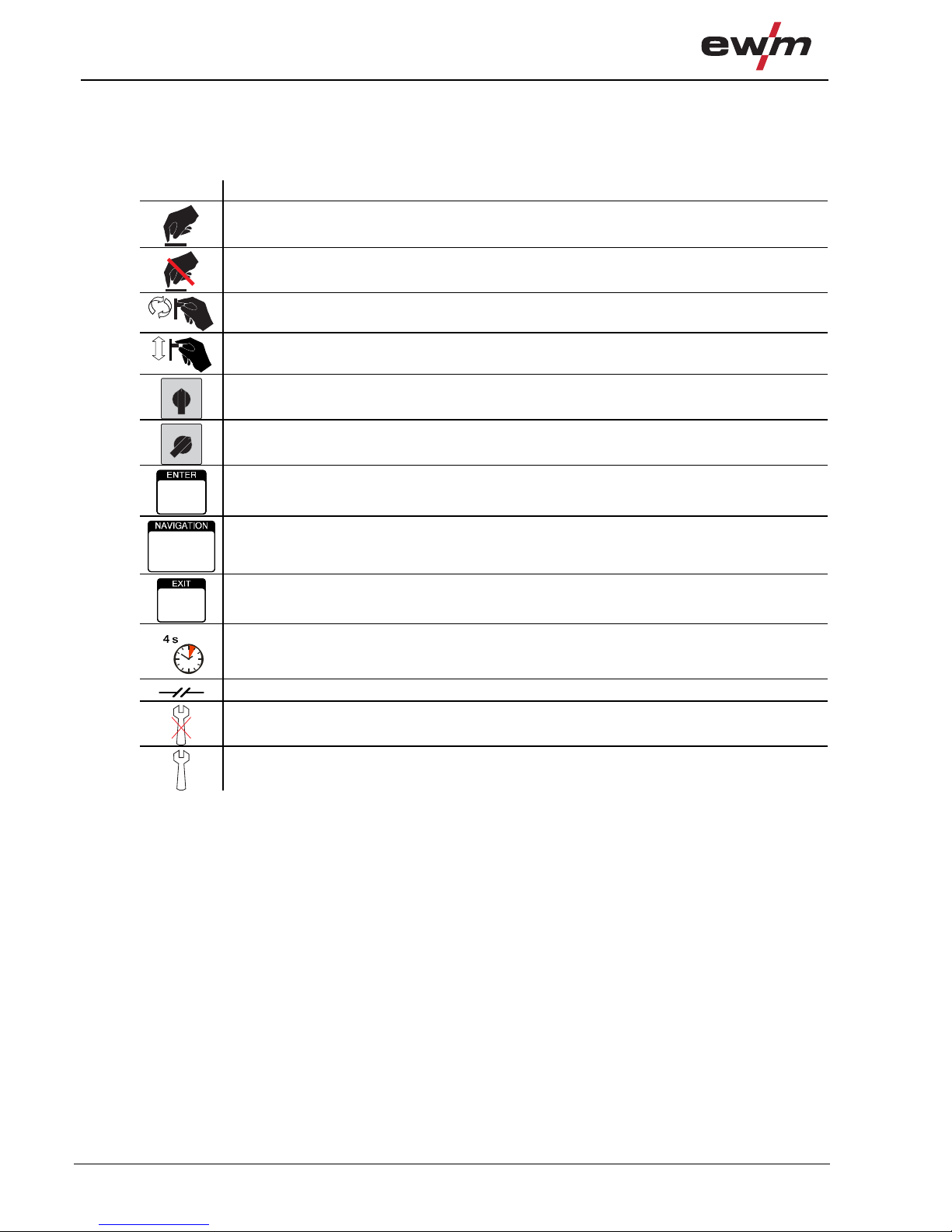
Symbol Description
Press
Do not press
Turn
Switch
0
1
Switch off machine
0
1
Switch on machine
ENTER (enter the menu)
NAVIGATION (Navigating in the menu)
EXIT (Exit the menu)
Time display (example: wait 4s/press)
Interruption in the menu display (other setting options possible)
Tool not required/do not use
Tool required/use

Safety instructions
General
099-002032-EW501
29.04.2010
7
2.2 General
DANGER
Electromagnetic fields!
The power source may cause electrical or electromagnetic fields to be produced which
could affect the correct functioning of electronic equipment such as IT or CNC devices,
telecommunication lines, power cables, signal lines and pacemakers.
• Observe the maintenance instructions! (see Maintenance and Testing chapter)
• Unwind welding lines completely!
• Shield devices or equipment sensitive to radiation accordingly!
• The correct functioning of pacemakers may be affected (obtain advice from a doctor if
necessary).
Do not carry out any unauthorised repairs or modifications!
To avoid injury and equipment damage, the unit must only be repaired or modified by
specialist, skilled persons!
The warranty becomes null and void in the event of unauthorised interference.
• Appoint only skilled persons for repair work (trained service personnel)!
Electric shock!
Welding machines use high voltages which can result in potentially fatal electric shocks
and burns on contact. Even low voltages can cause you to get a shock and lead to
accidents.
• Do not touch any live parts in or on the machine!
• Connection cables and leads must be free of faults!
• Switching off alone is not sufficient!
• Place welding torch and stick electrode holder on an insulated surf ace!
• The unit should only be opened by specialist staff after the mains plug has been unplugged!
• Only wear dry protective clothing!
• Wait for 4 minutes until the capacitors have discharged!
WARNING
Risk of injury due to radiation or heat!
Arc radiation results in injury to skin and eyes.
Contact with hot workpieces and sparks results in burns.
• Wear dry protective clothing (e.g. welding shield, gloves, etc.) according to the relevant
regulations in the country in question!
• Protect persons not involved in the work against arc beams and the risk of glare using safety
curtains!
Explosion risk!
Apparently harmless substances in closed containers may generate excessive pressur e
when heated.
• Move containers with inflammable or explosive liquids away from the working area!
• Never heat explosive liquids, dusts or gases by weldi ng or cutting!

Safety instructions
General
8
099-002032-EW501
29.04.2010
WARNING
Smoke and gases!
Smoke and gases can lead to breathing difficulties and poisoning. In addition, solvent
vapour (chlorinated hydrocarbon) may be converted into poisonous phosgene due to the
ultraviolet radiation of the arc!
• Ensure that there is sufficient fresh air!
• Keep solvent vapour away from the arc beam field!
• Wear suitable breathing apparatus if appropriate!
Fire hazard!
Flames may arise as a result of the high temperatures, stray sparks, glowing-hot parts
and hot slag produced during the welding process.
Stray welding currents can also result in flames forming!
• Check for fire hazards in the working area!
• Do not carry any easily flammable objects such as matches or lighters.
• Keep appropriate fire extinguishing equipment to hand in the working area!
• Thoroughly remove any residue of flammable substances from the workpiece before starting
welding.
• Only continue work on welded workpieces once they have cooled down.
Do not allow to come into contact with flammable material!
• Connect welding leads correctly!
Risk of accidents if these safety instructions are not observed!
Non-observance of these safety instructions is potentially fatal!
• Carefully read the safety information in this manual!
• Observe the accident prevention regulations in your country.
• Inform persons in the working area that they must observe the regulations!
CAUTION
Noise exposure!
Noise exceeding 70 dBA can cause permanent hearing damage!
• Wear suitable ear protection!
• Persons located within the working area must wear suitable ear protection!

Safety instructions
General
099-002032-EW501
29.04.2010
9
CAUTION
Obligations of the operator!
The respective national directives and laws must be observed for operation of the
machine!
• National implementation of the framework directive (89/391/EWG), as well as the associated
individual directives.
• In particular, directive (89/655/EWG), on the minimum regulations for safety and health
protection when staff members use equipment during work.
• The regulations regarding work safety and accident prevention for the respective country.
• Setting up and operating the machine according to IEC 60974-9.
• Check at regular intervals that users are working in a safety-conscious way.
• Regular checks of the machine according to IEC 60974-4.
Damage due to the use of non-genuine parts!
The manufacturer's warranty becomes void if non-genuine parts are used!
• Only use system components and options (power source s, welding torches, electrode
holders, remote controls, spare parts and replacement parts, etc.) from our range of
products!
• Only insert and lock accessory components into the relevant connection socket when the
machine is switched off.
Electromagnetic interference!
The machines are intended to be used in industrial areas, according to IEC 60974-10. If
they are used in residential areas, for example, problems may occur with ensuring
electromagnetic compatibility.
• Check whether interference is caused to other machines!

Safety instructions
Transport and installation
10
099-002032-EW501
29.04.2010
2.3 Transport and installation
WARNING
Incorrect handling of shielding gas cylinders!
Incorrect handling of shielding gas cylinders can result in serious and even fatal injury.
• Observe the instructions from the gas manufacturer and in any relevant regulations
concerning the use of compressed air!
• Place shielding gas cylinders in the holders provided for them and secure with fixing
devices.
• Avoid heating the shielding gas cylinder!
CAUTION
Risk of tipping!
There is a risk of the machine tipping over and injuring persons or being damaged itself
during movement and set up. Tilt resistance is guaranteed up to an angle of 10°
(according to IEC 60974-1, -3, -10).
• Set up and transport the machine on level, solid ground.
• Secure add-on parts using suitable equipment.
Damage due to supply lines not being disconnected!
During transport, supply lines which have not been disconnected (mains supply leads,
control leads, etc.) may cause hazards such as connected equipment tipping over and
injuring persons!
• Disconnect supply lines!
CAUTION
Equipment damage when not operated in an upright position!
The units are designed for operation in an upright position!
Operation in non-permissible positions can cause equipment damage.
• Only transport and operate in an upright position!

Safety instructions
Ambient conditions
099-002032-EW501
29.04.2010
11
2.4 Ambient conditions
CAUTION
Installation site!
The machine must not be operated in the open air and must only be set up and operated
on a suitable, stable and level base!
• The operator must ensure that the ground is non-slip and level, and provide sufficient
lighting for the place of work.
• Safe operation of the machine must be guaranteed at all times.
CAUTION
Equipment damage due to dirt accumulation!
Unusually high quantities of dust, acid, corrosive gases or substances may damage the
equipment.
• Avoid high volumes of smoke, vapour, oil vapour and grinding dust!
• Avoid ambient air containing salt (sea air)!
Non-permissible ambient conditions!
Insufficient ventilation results in a reduction in performance and equipment damage.
• Observe the ambient conditions!
• Keep the cooling air inlet and outlet clear!
• Observe the minimum distance of 0.5 m from obstacles!
2.4.1 In operation
Temperature range of the ambient air:
• -20 °C to +40 °C
Relative air humidity:
• Up to 50% at 40 °C
• Up to 90% at 20 °C
2.4.2 Transport and storage
Storage in an enclosed space, temperature range of the ambient air:
• -25 °C to +55 °C
Relative air humidity
• Up to 90% at 20 °C

Intended use
Applications
12
099-002032-EW501
29.04.2010
3 Intended use
This machine has been manufactured according to the latest developments in technology and current
regulations and standards. It must only be operated in line with the instructions on correct us age.
WARNING
Hazards due to improper usage!
Hazards may arise for persons, animals and material objects if the equipment is not used
correctly. No liability is accepted for any damages arising from improper usage!
• The equipment must only be used in line with proper usage and by trained or expert staff!
• Do not modify or convert the equipment improperly!
3.1 Applications
3.1.1 MMA welding
Manual arc welding or, for short, MMA welding. It is characterised by the fact that the arc burns between
a melting electrode and the molten pool. There is no external protection; any protection against the
atmosphere comes from the electrode.
3.1.2 TIG (Liftarc) welding
TIG welding process with arc ignition by means of workpiece contact.
3.2 Overview of device types
3.2.1 Cellulose electrode types (cel)
CEL device types are equipped with special Arcforce characteri stics.
These device types facilitate welding with cellulose electrode types which is safe for vertical-down
welding, especially in the lower output range.
3.2.2 Pole reversing switch (pws)
With PWS device types, the polarity of the welding current connections (pole reversal) can be changed
using a changeover switch on the machine or on the remote control.
Useful function with frequently changing electrode types without time-consuming reconnection of the
welding current connections (also directly at the operating point, in combination with a PWS remote
control).
3.2.3 Voltage reducing device (VRD/SVRD)
The voltage reducing device is a requirement in some countries and in many internal compan y safety
guidelines for power sources.
A distinction is made between two versions:
• VRD (Voltage Reduction Device) or
• SVRD (Slow Voltage Reduction Device)
Both switches meet the European standard (EN 60974-1:2005) and result in an increase in safety in
hazardous environments in particular (such as ship construction, pipe construction, mining).
VRD reduces the open circuit voltage to 12 V within 0.2 s and thus fulfils the Australian standard
(AS 1674.2-2003). SVRD reduces the open circuit voltage within 0.8 s to 12 V and thus fulfils the Russi an
standard (ГОСТ 12.2 007.8).
Intended use
Documents which also apply
099-002032-EW501
29.04.2010
13
3.3 Documents which also apply
3.3.1 Warranty
NOTE
For further information, please see the accompanying supplementary sheets "Machine
and Company Data, Maintenance and Testing, Warranty"!
3.3.2 Declaration of Conformity
The designated machine conforms to EC Directives and standards in terms of its design
and construction:
• EC Low Voltage Directive (2006/95/EC),
• EC EMC Directive (2004/108/EC),
This declaration shall become null and void in the event of unauthorised modifications, improperly
conducted repairs, non-observance of the deadlines for the repetition test and / or non-permitted
conversion work not specifically authorised by the manufacturer.
The original copy of the declaration of conformity is enclosed with the unit.
3.3.3 Welding in environments with increased electrical hazards
In compliance with IEC / DIN EN 60974, VDE 0544 the machines can be used in
environments with an increased electrical hazard.
3.3.4 Service documents (spare parts and circuit diagrams)
DANGER
Do not carry out any unauthorised repairs or modifications!
To avoid injury and equipment damage, the unit must only be repaired or modified by
specialist, skilled persons!
The warranty becomes null and void in the event of unauthorised interference.
• Appoint only skilled persons for repair work (trained service personnel)!
Original copies of the circuit diagrams are enclosed with the unit.
Spare parts can be obtained from the relevant authorised dealer.

Machine description – quick overview
Pico 300 cel
14
099-002032-EW501
29.04.2010
4 Machine description – quick overview
4.1 Pico 300 cel
4.1.1 Front view
Figure 4-1

Machine description – quick overview
Pico 300 cel
099-002032-EW501
29.04.2010
15
Item Symbol Description 0
1
Carrying strap
2 Transport bar
3
Carrying handle
4
Machine control
See Machine control – operating elements chapter
5 Cooling air inlet
6
Connection socket, "+" welding current
• TIG: Connection for workpiece lead
• MMA: Electrode holder or workpiece lead connection
7
Connection socket, 19-pole
Remote control connection
8
Connection socket, “-” welding current
Electrode holder or workpiece lead connection
9
Machine feet
10
Pole reversal changeover switch
The changeover switch is used to switch over the welding current polarity (“+” or “-” ) of
the electrode holder and workpiece lead connection sockets.
= Welding current polarity “+” on connection socket .
= Welding current polarity “-” on connection socket .
11
Connection socket, electrode holder
The welding current polarity (“+” or “-”) are based on the setting of the “Welding current
polarity changeover switch”.
12
Connection socket, workpiece lead
The welding current polarity (“+” or “-”) are based on the setting of the “Welding current
polarity changeover switch".

Machine description – quick overview
Pico 300 cel
16
099-002032-EW501
29.04.2010
4.1.2 Rear view
Figure 4-2

Machine description – quick overview
Pico 300 cel
099-002032-EW501
29.04.2010
17
Item Symbol Description 0
1
Main switch, machine on/off
2 Mains connection cable
3 Cooling air outlet
4
F4
Fuse
Solenoid switch pole reversal fuse
5
F5
Fuse
Solenoid switch pole reversal fuse

Machine description – quick overview
Machine control – Operating elements
18
099-002032-EW501
29.04.2010
4.2 Machine control – Operating elements
Figure 4-3

Machine description – quick overview
Machine control – Operating elements
099-002032-EW501
29.04.2010
19
Item Symbol Description 0
1
Collective interference signal light
For error messages, see the "Rectifying faults" chapter
2
Excess temperature signal light
In case of excess temperature, temperature monitors de-activate the power unit, and
the excess temperature control lamp comes on. Once the machine has cooled down,
welding can continue without any further measures.
3
Three-figure LED display
Display of welding current and voltage, welding parameters, error code
4
Switch display button
AMP Welding current display
VOLT Welding voltage display
5
Welding process button
MMA welding
TIG welding
6
“Arcforce” button (welding characteristics) according to electrode type
7
Select welding parameters button
This button is used to select the welding parameters depending on the welding process
and operating mode used.
8
Welding parameter setting rotary transducer
Setting of welding current and other welding parameter and their values
9 VRD
VRD open circuit voltage reduction
10 AMP%
Hotstart current signal light
50 % to 200 % of the main current
11 sec
Hotstart time signal light (0.1 s to 20 s)
12 AMP
Main current signal light

Design and function
General
20
099-002032-EW501
29.04.2010
5 Design and function
5.1 General
DANGER
Risk of injury from electric shock!
Contact with live parts, e.g. welding current sockets, is potentially fatal!
• Follow safety instructions on the opening pages of the operating instructions.
• Commissioning may only be carried out by persons who have the relevant expertise of
working with arc welding machines!
• Connection and welding leads (e.g. electrode holder, welding torch, workpiece lead,
interfaces) may only be connected when the machine is switched off!
CAUTION
Risk of burns on the welding current connection!
If the welding current connections are not locked, connections and leads heat up and can
cause burns, if touched!
• Check the welding current connections every day and lock by turning in clockwise direction, if
necessary.
CAUTION
Using protective dust caps!
Protective dust caps protect the connection sockets and ther efore the machine against
dirt and damage.
• The protective dust cap must be fitted if there is no accessory component being operated on
that connection.
• The cap must be replaced if faulty or if lost!
5.2 Machine cooling
To obtain an optimal duty cycle from the power components, the following precautions should be
observed:
• Ensure that the working area is adequately ventilated.
• Do not obstruct the air inlets and outlets of the machine.
• Do not allow metal parts, dust or other objects to get into the machine.
5.3 Workpiece lead, general
CAUTION
Risk of burns due to incorrect connection of the workpiece lead!
Paint, rust and dirt on the connection restrict the power flow and may lead to stray
welding currents.
Stray welding currents may cause fires and injuries!
• Clean the connections!
• Fix the workpiece lead securely!
• Do not use structural parts of the workpiece as a return lead for the welding current!
• Take care to ensure faultless power connections!

Design and function
Transport and installation
099-002032-EW501
29.04.2010
21
5.4 Transport and installation
CAUTION
Installation site!
The machine must not be operated in the open air and must only be set up and operated
on a suitable, stable and level base!
• The operator must ensure that the ground is non-slip and level, and provide sufficient
lighting for the place of work.
• Safe operation of the machine must be guaranteed at all times.
5.4.1 Adjusting the length of the carrying strap
NOTE
To demonstrate adjustment, lengthening the strap is shown in the figure. To shorten,
the strap's loops must be inched in the opposite direction.
Figure 5-1
Design and function
Mains connection
22
099-002032-EW501
29.04.2010
5.5 Mains connection
DANGER
Hazard caused by improper mains connection!
An improper mains connection can cause injuries or damage property!
• Only use machine with a plug socket that has a correctly fitted protective conductor.
• If a mains plug must be fitted, this may only be carried out by an electrician in accordance
with the relevant national provisions or regulations (any phase sequence for three-phase
machines)!
• Mains plug, socket and lead must be checked regularly by an electrician!
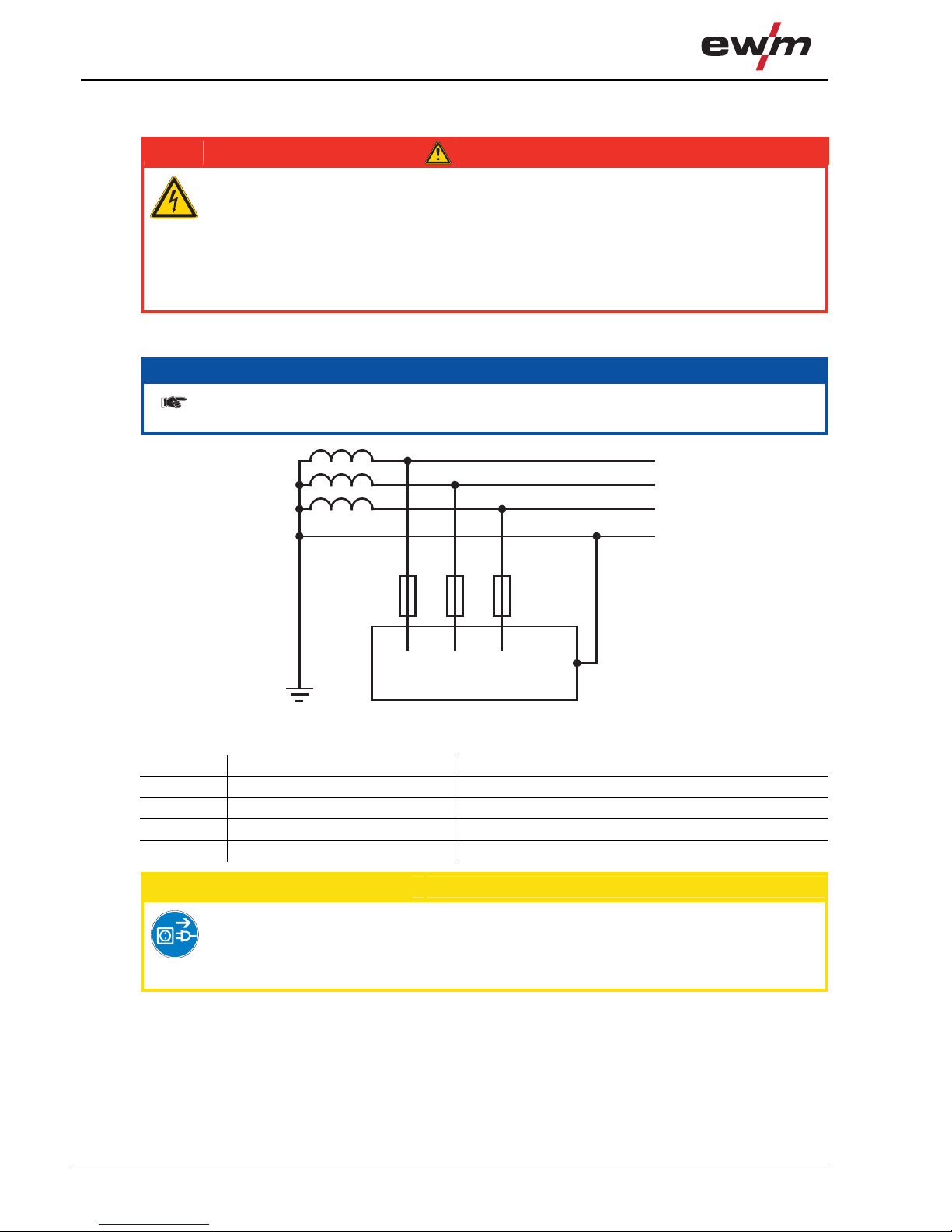
5.5.1 Mains configuration
NOTE
The machine may be connected to TN, TT or IT networks with a protective conductor (as
available).
L1
L3
L2
PE
Figure 5-2
Legend
Item Designation Colour code
L1 Outer conductor 1 black
L2 Outer conductor 2 brown
L3 Outer conductor 3 grey
PE Protective conductor green-yellow
CAUTION
Operating voltage - mains voltage!
The operating voltage shown on the rating plate must be consistent with the mains
voltage, in order to avoid damage to the machine!
• For mains fuse protection, please refer to the “Technical data” chapter!
• Insert mains plug of the switched-off machine into the appropriate socket.

Design and function
MMA welding
099-002032-EW501
29.04.2010
23
5.6 MMA welding
CAUTION
Risk of being crushed or burnt.
When replacing spent or new stick electrodes
• Switch off machine at the main switch
• Wear appropriate safety gloves
• Use insulated tongs to remove spent stick electrodes or to move welded workpieces and
• Always put the electrode holder down on an insulated surface.
NOTE
Polarity depends on the instructions from the electrode manufacturer given on the
electrode packaging.
5.6.1 Connecting the electrode holder and workpiece lead
5.6.1.1 Pico 300 cel
Figure 5-3
Item Symbol Description 0
1
Electrode holder
2
Connection socket for "+" welding current
Electrode holder or workpiece lead connection
3
Workpiece
4
Connection socket, “-” welding current
Workpiece lead or electrode holder connection
• Insert cable plug of the electrode holder into either the "+" or "-" welding current connection socket and
lock by turning to the right.
• Insert cable plug of the workpiece lead into either the "+" or "-" welding current connection socket and
lock by turning to the right.

Design and function
MMA welding
24
099-002032-EW501
29.04.2010
5.6.1.2 Pico 300 cel pws
NOTE
+ / -
The pole reversal changeover switch allows the welding current polarity (+/-) to be
changed without unplugging the electrode holder or workpiece leads. Changeover can
also be carried out using a suitable remote control (PWS). The polarity cannot be
changed during welding!
Figure 5-4

Design and function
MMA welding
099-002032-EW501
29.04.2010
25
Item Symbol Description 0
1
Electrode holder
2
Connection socket, electrode holder
The welding current polarity (“+” or “-”) are based on the setting of the “Welding current
polarity changeover switch”.
3
Workpiece
4
Connection socket, workpiece lead
The welding current polarity (“+” or “-”) are based on the setting of the “Welding current
polarity changeover switch".
5
Pole reversal changeover switch
The changeover switch is used to switch over the welding current polarity (“+” or “-” ) of
the electrode holder and workpiece lead connection sockets.
= Welding current polarity “+” on connection socket .
= Welding current polarity “-” on connection socket .
• Insert cable plug on the electrode holder into the welding current socket “ ” and lock by turning to
the right.
• Insert cable plug on the workpiece lead into the welding current socket “
” and lock by turning
to the right.

Design and function
MMA welding
26
099-002032-EW501
29.04.2010
5.6.2 Selecting MMA welding
Operating
element
Action Result
Select MMA welding process
The
signal light lights up in green
Set welding current
5.6.2.1 Arcforce (welding characteristics)
During the welding process, arcforce prevents the electrode sticking in the weld pool with increases in
current. This makes it easier to weld large-drop melting electrode types at low current strengths with a
short arc in particular.
NOTE
The selectable electrode characteristics on the machine control are guideline values.
Every characteristic can also be optimised for the relevant electrode types and their
welding properties (see chapter "Arcforce correction").
The electrode types used must be selected on the machine control to achieve the optimum
welding properties of the electrode types.
Control element Action Result
x x
The corresponding signal light displays the selection.
Electrode type allocation
Item Electrode type
a)
rutile
b)
rutile basic
c)
basic and
rutile/cellulose
d)
cellulose
Figure 5-5
Design and function
MMA welding
099-002032-EW501
29.04.2010
27
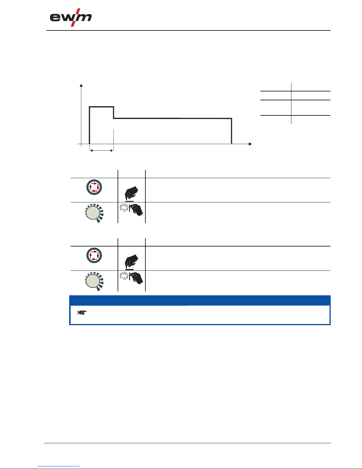
5.6.3 Hotstart current and Hotstart time
The hotstart device uses an increased ignition current to improve arc ignition. The parameters for
the hotstart current and time can be adjusted individually.
When the stick electrode has been struck, the arc ignites at the adjusted hotsta rt current AMP% (factory
setting: 120 % of main current)
and welds at this current until the hotstart time in seconds has elapsed
(factory setting: 1 second). The hotstart current then reduces to the main current set.
Symbol Meaning
AMP Main current
AMP% Hotstart
current
sec Hotstart time
t
AMP%
AMP
I
sec
Figure 5-6
Hotstart current
Control element Action Result
n x
Signal light AMP% lights up
Hotstart current is set as a percentage of the main current
(50 % to 200 %)
Hotstart time
Control element Action Result
n x
Signal light sec lights up
Hotstart time is set
(0.1 s to 20 s)
NOTE
After a waiting time of approx 5 s, the display changes back to the main current set and
the signal light AMP comes on.
Design and function
MMA welding
28
099-002032-EW501
29.04.2010
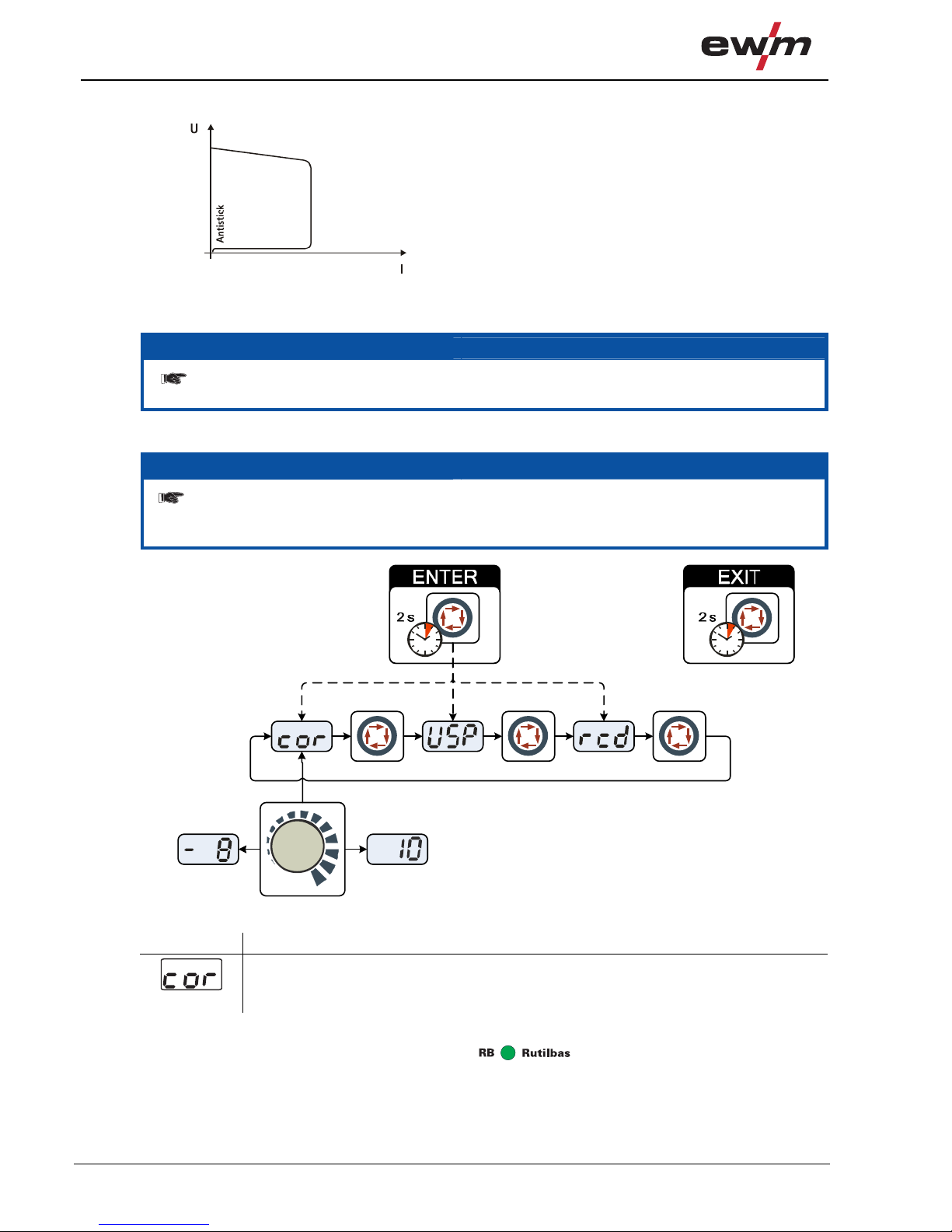
5.6.4 Antistick
Anti-stick prevents the electrode from annealing.
If the electrode sticks in spite of the Arcforce device, the
machine automatically switches over to the minimum
current within about 1 second to prevent the electrode
from overheating. Check the welding current setting
and correct according to the welding task!
Figure 5-7
5.6.5 Advanced settings
NOTE
To enable the greatest possible breadth of applications, the following parameters can
be adjusted or optimised for the welding task.
5.6.5.1 Arcforce correction (welding characteristics)
NOTE
To change the advanced setting parameters, hold down the "Welding parameters" button
for 2 seconds after selecting the welding process.
The following diagram shows the setting options.
Figure 5-8
Display Setting/selection
Arcforce correction (setting -8 to 10, factory setting 0)
• Increase value > harder arc
• Decrease value > softer arc
Example:
You are using a rutile/basic electrode type and set "
" accordingly on the machine control.
When welding the electrode type, you specify a hard or aggressive arc. You should now change the
arcforce setting in the direction of "less arcforce – softer arc" until the required result is achieved.

Design and function
TIG welding
099-002032-EW501
29.04.2010
29
5.7 TIG welding
5.7.1 Shielding gas supply (shielding gas cylinder for welding machine)
WARNING
Incorrect handling of shielding gas cylinders!
Incorrect handling of shielding gas cylinders can result in serious and even fatal injury.
• Observe the instructions from the gas manufacturer and in any relevant regulations
concerning the use of compressed air!
• Place shielding gas cylinders in the holders provided for them and secure with fixing
devices.
• Avoid heating the shielding gas cylinder!
CAUTION
Faults in the shielding gas supply.
An unhindered shielding gas supply from the shielding gas cylinder to the welding torch
is a fundamental requirement for optimum welding results. In addition, a blocked
shielding gas supply may result in the welding torch being destroyed.
• Always re-fit the yellow protective cap when not using the shielding gas connection.
• All shielding gas connections must be gas tight.
NOTE
Before connecting the pressure reducer to the gas cylinder, open the cylinder valve
briefly to expel any dirt.

Design and function
TIG welding
30
099-002032-EW501
29.04.2010
5.7.1.1 Connecting the shielding gas supply
• Secure the shielding gas cylinder using a securing chain.
Figure 5-9
Item Symbol Description 0
1
Pressure reducer
2
Shielding gas cylinder
3
Output side of the pressure reducer
4
Cylinder valve
• Tighten the pressure reducer screw connection on the gas bottle valve to be gas-tight.
• Screw the shielding gas connection of the welding torch to the pressure reduce r on the shielding gas
cylinder.
• Slowly open the gas cylinder valve.
• Open the rotating valve on the welding torch
Before each welding process, the rotating valve must be opened; after the welding process, it
must be closed.
• Set the required amount of shielding gas on the pressure reducer, about 4 - 15 l/min depending on the
current strength and the material.
Rule of thumb for gas flow rate:
Diameter of gas nozzle in mm corresponds to gas flow in l/min.
Example: 7 mm gas nozzle corresponds to 7 l/min gas flow

Design and function
TIG welding
099-002032-EW501
29.04.2010
31
5.7.2 Connecting a TIG welding torch with rotating gas valve
5.7.2.1 Pico 300 cel
Figure 5-10
Item Symbol Description 0
1
Workpiece
2
Connection socket for "+" welding current
Workpiece lead connection
3
Output side of the pressure reducer
4
Welding torch
5
Connection socket, "-" welding current
Welding current lead connection for TIG welding torch
• Insert the welding current plug on the welding torch into the welding current connection socket and
lock by turning to the right.
• Insert the cable plug on the work piece lead into the "+" welding current connection socket and lock by
turning to the right.
• Screw the shielding gas connection of the welding torch to the pressure reduce r on the shielding gas
cylinder.

Design and function
TIG welding
32
099-002032-EW501
29.04.2010
5.7.2.2 Pico 300 cel pws
NOTE
For machines with pole reversal switch (PWS), the welding current polarity is changed
as follows after selecting “TIG welding process”:
• Electrode holder connection socket = welding current polarity “-” ,
• Workpiece lead connection socket = welding current polarity “+”.
Figure 5-11
Item Symbol Description 0
1
Output side of the pressure reducer
2
Welding torch
3
Connection socket, TIG welding torch
4
Workpiece
5
Connection socket, workpiece lead
• Insert the welding current plug of the welding torch into the connection socket and lock by turning
to the right.
• Insert cable plug on the workpiece lead into the welding current socket “
” and lock by turning
to the right.
• Screw the shielding gas connection of the welding torch to the pressure reduce r on the shielding gas
cylinder.

Design and function
TIG welding
099-002032-EW501
29.04.2010
33
5.7.3 TIG welding selection
Control element Action Result
x x
TIG welding signal light
lights up
Main current setting
5.7.4 TIG arc ignition
5.7.4.1 Liftarc ignition
a) b) c)
Figure 5-12
The arc is ignited on contact with the workpiece:
a) Carefully place the torch gas nozzle and tungsten electrode tip onto the workpiece (liftarc current
flowing, regardless of the main current set).
b) Incline the torch towards the torch gas nozzle until there is a gap of approx. 2-3mm between the tip of
the electrode and the workpiece (arc ignites, current increases to the main current set).
c) Lift off the torch and swivel to the normal position.
Ending the welding process: Remove the torch from the workpiece until the arc goes out.

Design and function
Advanced settings
34
099-002032-EW501
29.04.2010
5.8 Advanced settings
NOTE
To enable the greatest possible breadth of applications, the following parameters can
be adjusted or optimised for the welding task.
5.8.1 Arc length restriction (USP)
Figure 5-13
Display Setting/selection
Arc length restriction
on Function switched on (TIG, factory setting)
off Function switched off (MMA, factory setting)

Design and function
Advanced settings
099-002032-EW501
29.04.2010
35
5.8.2 Activating the welding current actual value display
The welding current can be displayed as a setpoint value or an actual value on the welding data display.
The factory setting is that the welding current is displayed as a setpoint value (parameter "rcd" = off).
After switching over to the actual value display (parameter "rcd" = on), the following is displayed:
• The setpoint value is displayed in open circuit mode (when no welding current is flowing)
• If welding current is flowing, the welding data display switches over to the actual value
• After welding, the setpoint value is displayed once more
Figure 5-14
Display Setting/selection
Power display switching
on Actual value display
off Setpoint value display (factory setting)

Design and function
Voltage reducing device (VRD/SVRD)
36
099-002032-EW501
29.04.2010
5.9 Voltage reducing device (VRD/SVRD)
The signal light (VRD open circuit voltage reduction) indicates when the voltage reduction device has
been activated. This then ensures that the open circuit voltage between the electrode holder and the
workpiece is reduced to the permissible values.
The voltage reducing device is a requirement in some countries and in many internal compan y safety
guidelines for power sources.
A distinction is made between two versions:
• VRD (Voltage Reduction Device) or
• SVRD (Slow Voltage Reduction Device)
Both switches meet the European standard (EN 60974-1:2005) and result in an increase in safety in
hazardous environments in particular (such as ship construction, pipe construction, mining).
VRD reduces the open circuit voltage to 12 V within 0.2 s and thus fulfils the Australian standard
(AS 1674.2-2003). SVRD reduces the open circuit voltage within 0.8 s to 12 V and thus fulfils the Russi an
standard (ГОСТ 12.2 007.8).
5.10 Remote control
NOTE
The remote control is operated on the 19-pole remote control connection socket.
5.10.1 Foot-operated remote control RTF 1
Features
• Infinitely adjustable welding current (0% to 100%) depending on the preselected
main current on the welding machine.
5.10.2 Manual remote control RT 1
Functions
• Infinitely adjustable welding current (0% to 100%) depending on the preselected
main current on the welding machine.
5.10.3 Manual remote control RT PWS 1
Functions
• Infinitely adjustable welding current (0% to 100%) depending on the preselected
main current at the welding machine
• Pole reversing switch, suitable for machines with PWS function

Design and function
Dirt filter
099-002032-EW501
29.04.2010
37
5.11 Dirt filter
NOTE
These accessory components can be retrofitted as an option, see Accessories chapter.
The dirt filter can be used in places with unusually high levels of dirt and dust in the ambient air.
The filter reduces the duty cycle of the welding machine via the reduced flow of cooling air. The
filter must be disassembled and cleaned regularly depending on the level of dirt (blow out with
compressed air).
1
2
3
Figure 5-15
Item Symbol Description 0
1
4 fixing screws for dirt filter
2
Dirt filter with fixing plate
3 Cooling air inlet
• Fix dirt filter with 4 fixing screws on the front of the casing (cooling air inlet) of the welding machine.

Maintenance, care and disposal
General
38
099-002032-EW501
29.04.2010
6 Maintenance, care and disposal
DANGER
Risk of injury from electric shock!
Cleaning machines that are not disconnected from the mains can lead to serious injuries!
• Disconnect the machine completely from the mains.
• Remove the mains plug!
• Wait for 4 minutes until the capacitors have discharged!
6.1 General
When used in the specified environmental conditions and under normal operating condition s, this
machine is largely maintenance-free and requires a minimum of care.
There are some points, which should be observed, to guarantee fault-free operation of your welding
machine. Among these are regular cleaning and checking as descri bed below, depending on the pollution
level of the environment and the length of time the unit is in use.
6.2 Maintenance work, intervals
6.2.1 Daily maintenance tasks
• Mains supply lead and its strain relief
• Welding current cables (check that they are fitted correctly and secured)
• Gas tubes and their switching equipment (solenoid valve)
• Operating, message, safety and adjustment devices (Functional test)
• Other, general condition
6.2.2 Monthly maintenance tasks
• Casing damage (front, rear and side walls)
• Transport elements (strap, lifting lugs, handle)
• Selector switches, command devices, emergency stop devices, voltage re ducing devices, message
and control lamps
6.2.3 Annual test (inspection and testing during operation)
NOTE
The welding machine may only be tested by competent, capable personsl.
A capable person is one who, because of his training, knowledge and experience, is
able to recognise the dangers that can occur while testing welding power sources as
well as possible subsequent damage and who is able to implement the required safety
procedures.
For further information, please see the accompanying supplementary sheets "Machine
and Company Data, Maintenance and Testing, Warranty"!
The former term of repetition test has been replaced due to a change in the corresponding standard with
“Inspection and testing during operation”.
In addition to the regulations on the test given here, the relevant local laws and regulations must also be
observed.

Maintenance, care and disposal
Repair Work
099-002032-EW501
29.04.2010
39
6.3 Repair Work
DANGER
Do not carry out any unauthorised repairs or modifications!
To avoid injury and equipment damage, the unit must only be repaired or modified by
specialist, skilled persons!
The warranty becomes null and void in the event of unauthorised interference.
• Appoint only skilled persons for repair work (trained service personnel)!
Repair and maintenance work may only be performed by qualified authorised personnel; otherwise the
right to claim under warranty is void. In all service matters, always consult the dealer who supplied the
machine. Return deliveries of defective equipment subject to warranty may only be made through your
dealer. When replacing parts, use only original spare parts. When ordering spare parts, please quote the
machine type, serial number and item number of the machine, as well as the type designation and item
number of the spare part.
6.4 Disposing of equipment
NOTE
Proper disposal!
The machine contains valuable raw materials, which should be recycled, and
electronic components, which must be disposed of.
• Do not dispose of in household waste!
• Observe the local regulations regarding disposal!
6.4.1 Manufacturer's declaration to the end user
• According to European provisions (guideline 2002/96/EG of the European Parliament and the Council
of January, 27th 2003), used electric and electronic equipment may no longer be placed in u nsorted
municipal waste. It must be collected separately. The symbol depicting a waste container on wheels
indicates that the equipment must be collected separately.
This machine is to be placed for disposal or recycling in the waste separation systems provided for this
purpose.
• According to German law (law governing the distribution, taking b ack and environmentally correct
disposal of electric and electronic equipment (ElektroG) from 16.03.2005), used machines are to be
placed in a collection system separate from unsorted municipal waste. The publi c waste management
utilities (communities) have created collection points at which used equipment from private households
can be disposed of free of charge.
• Information about giving back used equipment or about collections can be obtained from the
respective municipal administration office.
• EWM participates in an approved waste disposal and recycling system and is registe red in th e Used
Electrical Equipment Register (EAR) under number WEEE DE 57686922.
• In addition to this, returns are also possible throughout Europe via EWM sales partners.
6.5 Meeting the requirements of RoHS
We, EWM HIGHTEC Welding GmbH Mündersbach, hereby co nfirm that all products supplied by us which
are affected by the RoHS Directive, meet the requirements of the RoHS (Directive 2002/95/EC).

Rectifying faults
Error messages (power source)
40
099-002032-EW501
29.04.2010
7 Rectifying faults
All products are subject to rigorous production checks and final checks. If, despite this, something fails to
work at any time, please check the product using the following flowchart. If none of the fault rectification
procedures described leads to the correct functioning of the product, please inform you r autho rised
dealer.
7.1 Error messages (power source)
NOTE
A welding machine error is indicated by the collective fault signal lamp (A1) lighting up
and an error code (see table) being displayed in the machine control display. In the event
of a machine error, the power unit shuts down.
• If multiple errors occur, these are displayed in succession.
• Document machine errors and inform service staff as necessary.
Error message Possible cause Remedy
"E 1" Electronics error Switch the machine off and back on again. If the
error persists, inform the service dept.
"E 2" Temperature error Allow machine to cool down.
"E 3" Electronics error See “E 1”.
"E 4" Electronics error See “E 1”.
"E 5" Electronics error See “E 1”.
"E 6" Balancing error in voltage
recording
"E 7" Balancing error in current
recording
Switch off the machine, place the electrode holder
in an insulated position and switch the machine
back on. If the error persists, inform the service
dept.
"E 8" Error in one of the electronics
supply voltages
Switch the machine off and back on again. If the
error persists, inform the service dept.
"E 9" Mains undervoltage Switch off the machine and check the mains
voltage.
"E10" Secondary excess voltage Switch the machine off and back on again. If the
error persists, inform the service dept.
"E11" Mains excess voltage Switch off the machine and check the mains
voltage.
"E12" Voltage reduction error (VRD) Switch the machine off and back on again. If the
error persists, inform the service dept.
Rectifying faults
Resetting welding parameters to the factory settings
099-002032-EW501
29.04.2010
41
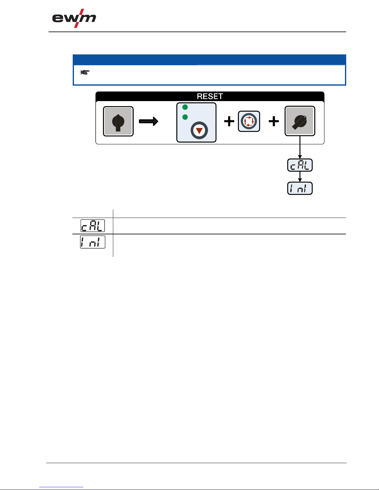
7.2 Resetting welding parameters to the factory settings
NOTE
All customised welding parameters that are stored will be replaced by the factory
settings.
0
1
0
1
AMP
VOLT
Figure 7-1
Display Setting/selection
Calibration
The machine will be calibrated for approx 2 seconds each time it is switched on.
Initialising
All customised welding parameters that are stored will be replaced by the factory
settings.

Technical data
Pico 300 cel
42
099-002032-EW501
29.04.2010
8 Technical data
8.1 Pico 300 cel
NOTE
Performance specifications and guarantee only in connection with original spare and
replacement parts!
MMA TIG
Current setting range 10 A-300 A 5 A-300 A
Voltage setting range 20.4 V-32.0 V 10.4 V-22.0 V
Duty cycle at 25 °C
30%
40%
60%
100%
300 A
250 A
190 A
300 A
260 A
200 A
Duty cycle at 40 °C
25%
30%
60%
100%
300 A
220 A
170 A
300 A
240 A
190 A
Load alternation
10 min. (60% DC ∧ 6 min. welding, 4 min. pause)
Open circuit voltage 99 V
Open circuit voltage (VRD) 12 V
Open circuit voltage (SVRD) 12 V
Mains voltage (tolerances) 3 x 400 V (+20% to -25%)
Frequency 50/60 Hz
Mains fuse (safety fuse, slow-blow) 16 A
Mains connection lead H07RN-F4G1,5
Max. connected load 12.1 kVA 8.3 kVA
Recommended generator rating 16.4 kVA
cosϕ at Imax
0.99
Insulation class/protection classification H/IP 23
Ambient temperature
-20 °C to +40 °C
Machine cooling/torch cooling Fan/gas
Workpiece lead 35 mm2
Dimensions L/W/H 515 x 185 x 350 mm
Dimensions L/W/H (pws) 515 x 185 x 445 mm
Weight 16.5 kg
Weight (pws) 23.5 kg
Constructed to standards
IEC 60974-1, -10
/

Accessories, options
Welding torch, electrode holder and workpiece lead
099-002032-EW501
29.04.2010
43
9 Accessories, options
9.1 Welding torch, electrode holder and workpiece lead
Type Designation Item no.
EH50 4M Electrode holder 092-000004-00000
WK50QMM 4M KL Workpiece cable, clamp 092-000003-00000
TIG 26V 4M ABITIG 26 V 4 m BCC-1 BHC-01 094-010979-00000
9.2 Remote controls and accessories
Type Designation Item no.
RT1 Remote control current 090-008097-00000
RA5 19POL 5M Remote control e.g. connection cable 092-001470-00005
RA10 19POL 10M Remote control e.g. connection cable 092-001470-00010
RA20 19POL 20M Remote control e.g. connection cable 092-001470-00020
RTF1 19POLE 5M Foot-operated remote control current with
connection cable
094-006680-00000
RV5M19 19POLE 5M Extension cable 092-000857-00000
9.2.1 Pico 300 cel pws
Type Designation Item no.
RT PWS1 Remote control vertical-down current, pole reversal 090-00819 9-00000
9.3 Options
Type Designation Item no.
ON FILTER Retrofit option, contamination filter for ai r inlet 092-001856-00000
9.4 General accessories
Type Designation Item no.
DM1 32L/MIN Manometer pressure reducer 094-000009-00000
5POLE/CEE/16A/M Machine plug 094-000712-00000

Appendix A
Overview of EWM branches
44
099-002032-EW501
29.04.2010
10 Appendix A
10.1 Overview of EWM branches
www.ewm-group.com
www.ewm-tv.de
EWM SCHWEISSTECHN IK-HANDELS-GMBH
Sachsstraße 28
50259 Pulheim · Deutschland
Tel: · Fax:+49 2234 697-047 -048
www.ewm-grwm-group.com/handel · nl-koeln@ewm-group.com
EWM HIGHTECWELDING s.r.o.
Tr. 9 718. kvetna
407 53 Ji ík ovř ·Tschechische Republik
Tel: + · Fax:420 412 358-551 -20
www.ewm-group.com/cz · info.cz@ewm-group.com
EWM HIGHTECWELDING UK Ltd.
Unit B CoopiesWay2
Coopies Lane Industrial Estate
Morpeth · Northumberland · NE JN· Großbritannien61 6
Tel: · Fax:+44 1670 505875 -514305
www.ewm-group.com/uk · info.uk@ewm-group.com
EWM HIGHTECWELDING (Kunshan) Ltd.
10 Yuanshan Road,Kunshan
New & High-tech Industry Development Zone
Kunshan · Jiangsu · ·Volksrepublik China215300
Tel: + · Fax:86 512 57867-188 -182
www.ewm-group.com/cn · info.cn@ewm-group.com
EWM HIGHTECWELDING GmbH
Dr.Günter-Henle-Straße 8
56271 Mündersbach
Deutschland
Tel: +49 2680 181-0 · Fax: -244
www.ewm-group.com · info@ewm-group.com
EWM SCHWEISSTECHN IK-HANDELS-GMBH
In der Florinskaul 14-16
56218 Mülheim-Kärlich · Deutschland
Tel: +49 261 988898-0 · Fax: -244
www.ewm-group.com/handel · nl-muelheim@ewm-group.com
EWM HIGHTECWELDING GmbH
Niederlassung Nord
Lindenstraße a1
38723 Seesen-Rhüden · Deutschland
Tel: · Fax:+49 5384 90798-0 -20
www.ewm-group.com/handel · nl-nord@ewm-group.com
EWM HIGHTECWELDING SALES s.r.o.
Prodejní a poradenské centrum
Tyr
š
ova 2106
256 01 Bene ov u Prahy · Tschechische Republik
š
Tel: · Fax:+420 317 729-517 -712
www.ewm-group.com/cz · sales.cz@ewm-group.com
EWM HIGHTECWELDING GmbH
Scharnsteinerstraße 15
4810 Gmunden · Österreich
Tel: · Fax:+43 7612 778 02-0 -20
www.ewm-group.com/at · info.at@ewm-group.com
EWM HIGHTECWELDING FZCO
Regional Off
ice M
iddle East
JAFZAView 18 14 05F · P.O. Box 262851
Jebel Ali Free Zone · Dubai · Vereinigte Arabische Emirabische Emirate
Tel: · Fax:+971 4 8857-789 -500
www.ewm-group.com/me · info.me@ewm-group.com
 Loading...