

Page 1
EWM
HIGHTEC WELDING GmbH
Dr. Günter-Henle-Straße 8 • D-56271 Mündersbach
Fon +49 2680 181-0 • Fax +49 2680 181-244
GB
Operating instructions
Compact welding machines for MIG/MAG,
TIG and MMA welding
PHOENIX 333 PROGRESS PULS forceArc
N. B. These operating instructions must be read before commissioning.
Failure to do so may be dangerous.
Machines may only be operated by personnel who are familiar with the appropriate safety
regulations.
The machines bear the conformity mark and thus comply with the
• EC Low Voltage Directive (2006/95/ EG)
• EC EMC Directive (2004/108/ EG)
In compliance with IEC 60974, EN 60974, VDE 0544 the machines can be used in environments
with an increased electrical hazard.
© 2008 Subject to alteration.
Item No.: 099-005073-EWM01
Revised: 10.04.2008
Page 2

Dear customer,
Congratulations! You have chosen a quality product from EWM HIGHTEC WELDING GmbH.
EWM machines provide results of the highest perfection thanks to their PREMIUM quality. Therefore
we are happy to provide you with a full 3-year warranty according to our operating instructions.
We develop and produce quality! From individual components to the final product, we retain sole
responsibility for our machines.
In all their high-tech components, our welding machines embody future-oriented advanced technology
at the utmost level of quality. Each of our products is carefully checked; we guarantee that the material
and processing of our products is faultless.
These operating instructions contain everything about commissioning the machine, notes regarding
safety, maintenance and care, technical data as well as information regarding the warranty. Please
heed all these notes to ensure many years of safe operation of the machine.
Thank you for the trust that you have placed in us. We look forward to a long-term partnership with you
in the spirit of “ONCE EWM – ALWAYS EWM”.
Yours sincerely,
EWM HIGHTEC WELDING GmbH
Bernd Szczesny
Executive management
Page 3
Machine and Company Data
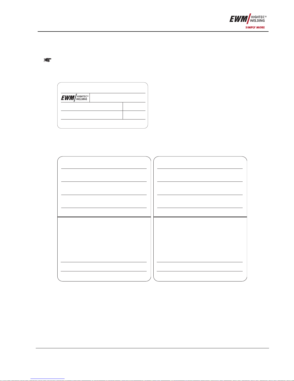
Please enter the EWM machine data and your company’s data in the appropriate fields.
CE
EWM HIGHTEC WELDING GMBH
D-56271 MÜNDERSBACH
TYP:
ART:
SNR:
PROJ:
GEPRÜFT/CONTROL:
Name of Customer / company
Adress
Post code / Place
Country
Stamp / Signature of EWM-distibutor
Date of purchase
Name of Customer / company
Adress
Post code / Place
Country
Stamp / Signature of EWM-distibutor
Date of purchase
3
Page 4

Contents
For your safety
4 Item No.: 099-005073-EWM01
1 Contents
1 Contents..................................................................................................................................................4
2 Safety instructions.................................................................................................................................9
2.1 For your safety...............................................................................................................................9
2.2 Transport and installation.............................................................................................................11
2.2.1 Ambient conditions .......................................................................................................11
2.3 Notes on the use of these operating instructions.........................................................................12
3 Technical data.......................................................................................................................................13
3.1 PHOENIX 333 PROGRESS KG ..................................................................................................13
4 Machine description.............................................................................................................................14
4.1 PHOENIX 333 PROGRESS KG ..................................................................................................14
4.1.1 Front view.....................................................................................................................14
4.1.2 Rear view......................................................................................................................16
4.1.3 Inside view....................................................................................................................18
5 Functional characteristics...................................................................................................................20
5.1 Machine control – Operating elements........................................................................................20
5.1.1 Welding machine control ..............................................................................................20
5.1.1.1 Covered operating elements.........................................................................22
5.2 MIG/MAG welding........................................................................................................................24
5.2.1 Definition of MIG/MAG welding tasks...........................................................................24
5.2.2 Selecting MIG/MAG welding tasks...............................................................................24
5.2.2.1 Basic welding parameters.............................................................................24
5.2.2.2 Operating mode.............................................................................................24
5.2.2.3 Welding type..................................................................................................24
5.2.2.4 Choke effect / dynamics................................................................................25
5.2.2.5 Superpulses ..................................................................................................25
5.2.2.6 Wire burn-back..............................................................................................25
5.2.3 MIG/MAG operating point.............................................................................................26
5.2.3.1 Selecting the display unit ..............................................................................26
5.2.3.2 Operating point setting using material thickness, welding current, wire
speed..................................................................................................................
26
5.2.3.3 Arc length correction setting..........................................................................26
5.2.3.4 Wire burn-back..............................................................................................27
5.2.3.5 Accessory components for operating point setting .......................................27
5.2.4 MIG/MAG welding data display....................................................................................27
5.2.5 MIG/MAG functional sequences / operating modes.....................................................28
5.2.5.1 Explanation of signs and functions................................................................28
5.2.5.2 Non-latched mode.........................................................................................29
5.2.5.3 Non-latched operation with superpulse.........................................................29
5.2.5.4 Special, non-latched......................................................................................30
5.2.5.5 Spots .............................................................................................................31
5.2.5.6 Special, non-latched with superpulse............................................................32
5.2.5.7 Latched mode................................................................................................33
5.2.5.8 Latched mode with superpulse .....................................................................34
5.2.5.9 Latched mode with alternating welding process ...........................................35
5.2.5.10 Latched special ...........................................................................................36
5.2.5.11 Latched special with welding process alternation.......................................37
5.2.5.12 Special, latched with superpulse.................................................................38
5.2.5.13 Latched special with alternating welding process.......................................39
5.2.6 MIG/MAG program sequence ("Program steps" mode)...............................................40
5.2.6.1 Selecting the program sequence parameters using wire feed unit
control M3.70......................................................................................................
40
5.2.6.2 MIG/MAG overview of parameters, M3.70....................................................41
5.2.6.3 Example, tack welding (non-latched)............................................................42
5.2.6.4 Example, aluminium tack welding (non-latched special) ..............................42
5.2.6.5 Example, aluminium welding (latched special) .............................................43
Page 5

Contents
For your safety
Item No.: 099-005073-EWM01 5
5.2.6.6 Example, visible seams (latched super pulse)..............................................44
5.2.6.7 Welding process changeover........................................................................45
5.2.7 Main program A mode..................................................................................................46
5.2.7.1 Selecting parameters (program A) using wire feed unit control M3.70.........48
5.2.8 MIG/MAG automatic cut-out.........................................................................................48
5.2.9 Standard MIG/MAG torch.............................................................................................48
5.2.10 MIG/MAG special-torches ............................................................................................48
5.2.11 Special parameter, “M3.70/M3.71”...............................................................................49
5.2.11.1 Special parameters list................................................................................49
5.2.11.2 Selecting, changing and saving parameters...............................................50
5.2.11.3 Reset to factory settings .............................................................................50
5.2.11.4 Ramp time for wire inching (P1)..................................................................50
5.2.11.5 Program "0", releasing the program block (P2)..........................................50
5.2.11.6 Display mode torch power control (P3).......................................................50
5.2.11.7 Program limit (P4).......................................................................................51
5.2.11.8 Special cycle in the operating modes special latched and non-latched
(P5)
51
5.2.11.9 Enabling special JOBs SP1 to SP3 (P6) ....................................................51
5.2.11.10 Correction operation, threshold value setting (P7)...................................51
5.2.11.11 Program changeover with standard torch (P8).........................................52
5.2.11.12 N cycle setting...........................................................................................54
5.2.11.13 Latched/special-latched tap start (P9)......................................................54
5.2.11.14 "Single or dual operation" (P10) setting....................................................54
5.2.11.15 Latched special tapping time setting (P11)...............................................54
5.2.11.16 JOB list switching (P12)............................................................................55
5.2.11.17 Creating user-defined JOB lists................................................................55
5.2.11.18 Copying JOBs, "Copy to" function ............................................................56
5.2.11.19 Lower and upper limits of the remote JOB changeover process
(P13,P14)...........................................................................................................
56
5.2.11.20 Hold function (P15)...................................................................................56
5.2.11.21 Software key switch (SCH) .......................................................................56
5.3 TIG welding..................................................................................................................................57
5.3.1 TIG welding task selection ...........................................................................................57
5.3.2 TIG welding current setting ..........................................................................................57
5.3.3 TIG arc ignition.............................................................................................................57
5.3.3.1 Liftarc ............................................................................................................57
5.3.4 TIG function sequences / operating modes .................................................................58
5.3.4.1 Explanation of signs and functions ...............................................................58
5.3.4.2 Non-latched mode.........................................................................................59
5.3.4.3 Special, non-latched .....................................................................................59
5.3.4.4 Latched mode ...............................................................................................60
5.3.4.5 Latched special.............................................................................................61
5.3.5 TIG automatic cut-out...................................................................................................61
5.4 MMA welding ...............................................................................................................................62
5.4.1 MMA welding task selection.........................................................................................62
5.4.2 MMA welding current setting........................................................................................62
5.4.3 Arcforcing .....................................................................................................................62
5.4.4 Hotstart.........................................................................................................................62
5.4.5 Antistick........................................................................................................................62
5.5 Interfaces.....................................................................................................................................63
5.5.1 Automation interface.....................................................................................................63
5.5.2 RINT X11 robot interface..............................................................................................64
5.5.3 BUSINT X10 Industrial bus interface............................................................................64
5.5.4 DVINT X11 Wire feed interface....................................................................................64
5.5.5 PC Interfaces................................................................................................................64
5.5.6 Setting options, internal................................................................................................64
5.5.6.1 Switching between Push/Pull and intermediate drive...................................64
5.6 Remote control.............................................................................................................................65
Page 6

Contents
For your safety
6 Item No.: 099-005073-EWM01
5.6.1 R10 manual remote control ..........................................................................................65
5.6.2 Manual remote control R20 ..........................................................................................66
5.6.3 R40 manual remote control ..........................................................................................66
5.7 Resetting JOBs (welding tasks) to the factory settings................................................................67
5.7.1 Resetting a single JOB.................................................................................................67
5.7.2 Resetting all JOBs........................................................................................................67
6 Commissioning.....................................................................................................................................68
6.1 General.........................................................................................................................................68
6.2 Area of application – proper usage..............................................................................................68
6.3 Installation....................................................................................................................................68
6.4 Mains connection.........................................................................................................................68
6.5 Machine cooling...........................................................................................................................68
6.5.1 Cooling module connection ..........................................................................................69
6.6 Workpiece lead, general ..............................................................................................................69
6.7 MIG/MAG welding........................................................................................................................70
6.7.1 Welding torch connection .............................................................................................70
6.7.2 Connection for workpiece lead .....................................................................................72
6.7.3 Fixing of the pin reel (adjustment of the pre-tensioning) ..............................................73
6.7.4 Inserting the wire spool.................................................................................................74
6.7.5 Changing the wire feed rollers......................................................................................74
6.7.6 Inching the wire electrode.............................................................................................75
6.7.7 Spool brake setting.......................................................................................................76
6.8 TIG welding..................................................................................................................................76
6.8.1 Welding torch connection .............................................................................................77
6.9 MMA welding................................................................................................................................78
6.10 Shielding gas supply....................................................................................................................80
6.10.1 Connecting the shielding gas supply............................................................................80
6.10.2 Gas test ........................................................................................................................81
6.10.3 “Rinse tube package” function......................................................................................81
6.10.4 Setting the shielding gas quantity.................................................................................81
7 Maintenance and testing .....................................................................................................................82
7.1 General.........................................................................................................................................82
7.2 Cleaning.......................................................................................................................................82
7.3 Test ..............................................................................................................................................82
7.3.1 Test equipment.............................................................................................................82
7.3.2 Scope of the test...........................................................................................................83
7.3.3 Visual inspection...........................................................................................................83
7.3.4 Measuring the open circuit voltage...............................................................................83
7.3.5 Measurement of insulation resistance..........................................................................83
7.3.6 Measuring the leakage current (protective conductor and contact current).................84
7.3.7 Measurement of protective conductor resistance.........................................................84
7.3.8 Functional test of the welding machine ........................................................................84
7.3.9 Documentation of the test.............................................................................................84
7.4 Repair Work .................................................................................................................................85
7.5 Disposing of equipment................................................................................................................86
7.5.1 Manufacturer's declaration to the end user..................................................................86
7.6 Meeting the requirements of RoHS..............................................................................................86
8 Warranty................................................................................................................................................87
8.1 General Validity............................................................................................................................87
8.2 Warranty Declaration ...................................................................................................................88
9 Operating problems, causes and remedies.......................................................................................89
9.1 Error messages (power source)...................................................................................................89
10 Accessories, options ...........................................................................................................................90
10.1 General accessories ....................................................................................................................90
10.2 Remote control / connection cable...............................................................................................90
10.3 Wire feed rollers...........................................................................................................................91
10.3.1 V-Nut wire conveyors....................................................................................................91
Page 7

Contents
For your safety
Item No.: 099-005073-EWM01 7
10.3.2 U-Nut wire conveyors ...................................................................................................91
10.3.3 Wire feed rollers for cored wire ....................................................................................91
10.3.4 Conversion sets............................................................................................................91
10.4 Options.........................................................................................................................................92
10.5 Computer communication............................................................................................................92
11 Circuit diagrams...................................................................................................................................93
11.1 PHOENIX 333 PROGRESS KG..................................................................................................93
12 Appendix A ...........................................................................................................................................96
12.1 Declaration of Conformity ............................................................................................................96
13 Appendix B ...........................................................................................................................................97
13.1 JOB-List .......................................................................................................................................97
Page 8

Contents
For your safety
8 Item No.: 099-005073-EWM01
Page 9
Safety instructions
For your safety
Item No.: 099-005073-EWM01 9
2 Safety instructions
2.1 For your safety
Observe accident prevention regulations!
Ignoring the following safety procedures can be fatal!
Proper usage
This machine has been manufactured according to the latest developments in technology and
current regulations and standards. It is to be operated only for the use for which it was designed
(see chapter Commissioning/Area of application).
Improper usage
However, this machine may be a hazard to persons, animals and property if it is
• not used as directed
• used by unskilled persons who have not been trained
• modified or converted improperly
Our operating instructions will provide you with an introduction into the safe use of the machine.
Therefore please read them carefully and only start work when you are familiar with them.
Any person involved in the operation, maintenance and repair of this machine must read and
follow these operating instructions, especially the safety precautions. Where appropriate, this
should be confirmed by signature.
Furthermore, the
• relevant accident prevention regulations,
• generally accepted safety regulations,
• local regulations, etc. must be observed.
Before undertaking welding tasks, put on prescribed dry protective clothing, e.g. gloves.
• Protect eyes and face with protective visor.
Electric shocks can be fatal!
• Do not touch any live parts in or on the machine!
• The machine may only be connected to correctly earthed sockets.
• Only operate with intact connection lead including protective conductor and safety plug.
• An improperly repaired plug or damaged mains cable insulation can cause electric shocks.
• The machine may only be opened by qualified and authorised specialist staff.
• Disconnect from the mains before opening. Switching off is not sufficient. Wait for 2 minutes until the
capacitors have discharged.
• Always put down welding torch, stick electrode holder in an insulated condition.
• The machine must not be used to defrost pipes!
Even touching low voltages can cause you to get a shock and lead to accidents, so:
• Protect yourself from falling before working on platforms or scaffolding.
• During welding ensure that you operate earth tongs, torch and workpiece correctly, and not in ways for
which they are not intended. Do not touch live parts with bare skin.
• Only replace electrodes when wearing dry gloves.
• Never use torches or earth cables with damaged insulation.
Smoke and gases can lead to breathing difficulties and poisoning.
• Do not breathe in smoke and gases.
• Ensure that there is sufficient fresh air.
• Keep solvent vapours away from the arc radiation area. Chlorinated hydrocarbon fumes can be
converted into poisonous phosgene by ultraviolet radiation.
Page 10
Safety instructions
For your safety
10 Item No.: 099-005073-EWM01
Workpiece, flying sparks and droplets are hot!
• Keep children and animals well away from the working area. Their behaviour is unpredictable.
• Move containers with inflammable or explosive liquids away from the working area. There is a danger
of fire and explosion.
• Never heat explosive liquids, dusts or gases by welding or cutting. There is also a danger of
explosions when apparently harmless substances develop high pr essures in enclosed containers by
heating.
Take care to avoid fire hazards
• Any kind of fire hazards must be avoided. Flames can form e.g. when sparks are flying, when parts
are glowing or hot slag is present.
• A constant check must be kept on whether fire hazards have arisen in the working area.
• Highly inflammable objects, such as matches and cigarette lighters for example, must not be carried in
trouser pockets.
• You must ensure that fire extinguishing equipment - appropriate for the welding process - is a va ilable
close to the welding work area and that this equipment can be accessed easily.
• Containers in which fuels or lubricants have been present must be thoroughly cleaned before welding
begins. It is not sufficient simply for the receptacle to be empty.
• After a workpiece has been welded, it must only be touched or brought into contact with inflammable
material when it has cooled down sufficiently.
• Loose welding connections can comple t e ly destroy protective conductor systems of interior
installations and cause fires. Before beginning welding work, ensure that the earth tongs are properly
fixed to the workpiece or welding bench and that there is a direct electrical connection from the
workpiece to the power source.
Noise exceeding 70 dBA can cause permanent hearing damage!
• Wear suitable earmuffs or plugs.
• Ensure that other people who spend time in the working area are not inconvenienced by the noise.
Interference by electrical and electromagnetic fields is possible e.g. from the welding machine or
from the high-voltage pulses of the ignition unit.
• As laid down in Electromagnetic Compatibility Standard EN 50199, the machines are intended for use
in industrial areas; if they are operated in residential environments, for example, problems may occur
in ensuring electromagnetic compatibility.
• The functioning of heart pacemakers can be adversely affected when you are standing near the
welding machine.
• It is possible that electronic equipment (e.g. EDP, CNC equipment) in the vicinity of the welding site
could malfunction.
• Other mains supply leads, control leads, signal and teleco mmunications leads above, under and near
the welding device may be subject to interference.
Electromagnetic interference must be reduced to a level that no longer constitutes interference.
Possible reduction measures:
• Welding machines must be serviced regularly. (see Chap. Maintenance and care)
• Welding leads should be as short as possible and run closely together on or near to the ground.
• Selective shielding of other leads and equipment in the environment can reduce radiation.
Repair and modifications may only carried out by authorised, trained, specialist staff.
The warranty becomes null and void in the event of unauthorised interference.
Page 11
Safety instructions
Transport and installation
Item No.: 099-005073-EWM01 11
2.2 Transport and installation
The machines may only be transported and operated in an upright position.
Before carrying away or moving, pull out mains plug and place on the machine.
When setting up the machine, resistance to tilting is only guaranteed up to an angle of 10°
(as specified in EN 60974-1).
Secure the gas cylinder!
• Place shielding gas cylinders in the holders provided for them and secure with safety chains.
• Take care when handling cylinders; do not throw or heat, guard against them toppling over.
• When moving by crane, take off the gas cylinder from the welding machine.
2.2.1 Ambient conditions
This machine must not be operated in any area where any risk of explosion exists.
The following conditions must be observed during operation:
Temperature range of the ambient air
• During welding: -10°C to +40°C *),
• For transport and storage: -25°C to +55°C *)
*) Using the appropriate coolant.
Relative air humidity
• up to 50% at 40°C
• up to 90% at 20°C
The ambient air must be free of unusual amounts of dust, acids, corrosive gases or substance s, etc.,
assuming these are not produced by the welding process.
Examples of unusual operating conditions:
• unusual corrosive smoke,
• vapour,
• excessive oil vapour,
• unusual vibrations or jolts,
• excessive quantities of dust such as grinding dust etc.,
• severe weather conditions,
• unusual conditions near the coast or on board ship.
When setting up the machine, ensure a free inlet and outlet of air.
The machine is tested to protection class IP23, i.e.:
• Protection against penetration of solid foreign bodies ∅ > 12mm,
• Protection against water spray up to an angle of 60° to the vertical.
Page 12
Safety instructions
Notes on the use of these operating instructions
12 Item No.: 099-005073-EWM01
2.3 Notes on the use of these operating instructions
These operating instructions are arranged into chapters.
To help you find your way around more quickly, in the margins you will occa sionally see symbols along
with the sub-headings. These symbols refer to particularly important passages of text which are graded
as follows depending on their importance:
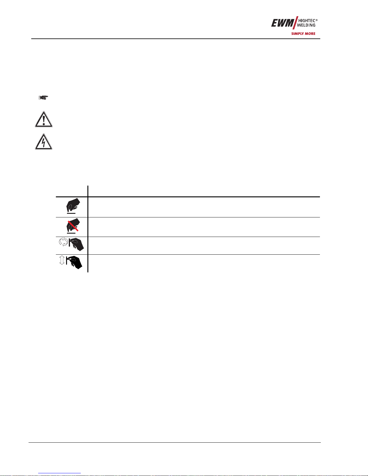
Please note:
Technical features which users must observe.
Warning:
Working and operating procedures which must be followed precisely to avoid damaging or
destroying the machine.
Caution:
Working and operating procedures which must be followed precisely to avoid risk to persons and
includes the "Warning" symbol.
Instructions and lists detailing step-by-step actions in given situatio ns can be recognised by bullet points,
e.g.:
• Insert the welding current lead socket into the relevant socket and lock.
Symbol Description
Press
Do not press
Turn
Switch
Page 13
Technical data
PHOENIX 333 PROGRESS KG
Item No.: 099-005073-EWM01 13
3 Technical data
3.1 PHOENIX 333 PROGRESS KG
PHOENIX 333
Setting range: Welding current/voltage
MMA
5A/20.2V–330A/33.2V
TIG
5A/10.2V–330A/23.2V
MIG/MAG
5A/14.2V–330A/30.5V
Duty cycle at 40°C ambient temperature
25%DC
330A
60%DC
250A
100%DC
210A
Duty cycle at 20C ambient temperature
30%DC
330A
60%DC
260A
100%DC
220A
Load alternation
10 min. (60% DC
∧
6 min. welding, 4 min. break)
Open circuit voltage
103V
Mains voltage (tolerances)
3 x 400V (-25% to +20%)
3 x 415V (-25% to +15%)
Frequency
50/60Hz
Mains fuse (safety fuse, slow-blow)
3 x 16A
Mains connection lead
H07RN-F4G2.5
Max. connected power
13.0kVA
Recommended generator rating
17.5kVA
Cosϕ/efficiency
0.99/89%
Insulation class/protection
classification
H/IP 23
Ambient temperature
-10C to +40C
Machine/torch cooling
Fan/gas
WF speed
0.5m/min. to 20m/min.
Standard WF rollers
1.0 + 1.2mm (steel wire)
Drive
4-roller (37mm)
Torch connection
Euro-central or Dinse-central
Workpiece lead
70mm
2
Dimensions L/W/H [mm]
605 x 335 x 520
Weight
55.5kg
Constructed to standards
IEC 60974/EN 60974/VDE 0544
EN 50199/VDE 0544 Part 206
/
Page 14
Machine description
PHOENIX 333 PROGRESS KG
14 Item No.: 099-005073-EWM01
4 Machine description
4.1 PHOENIX 333 PROGRESS KG
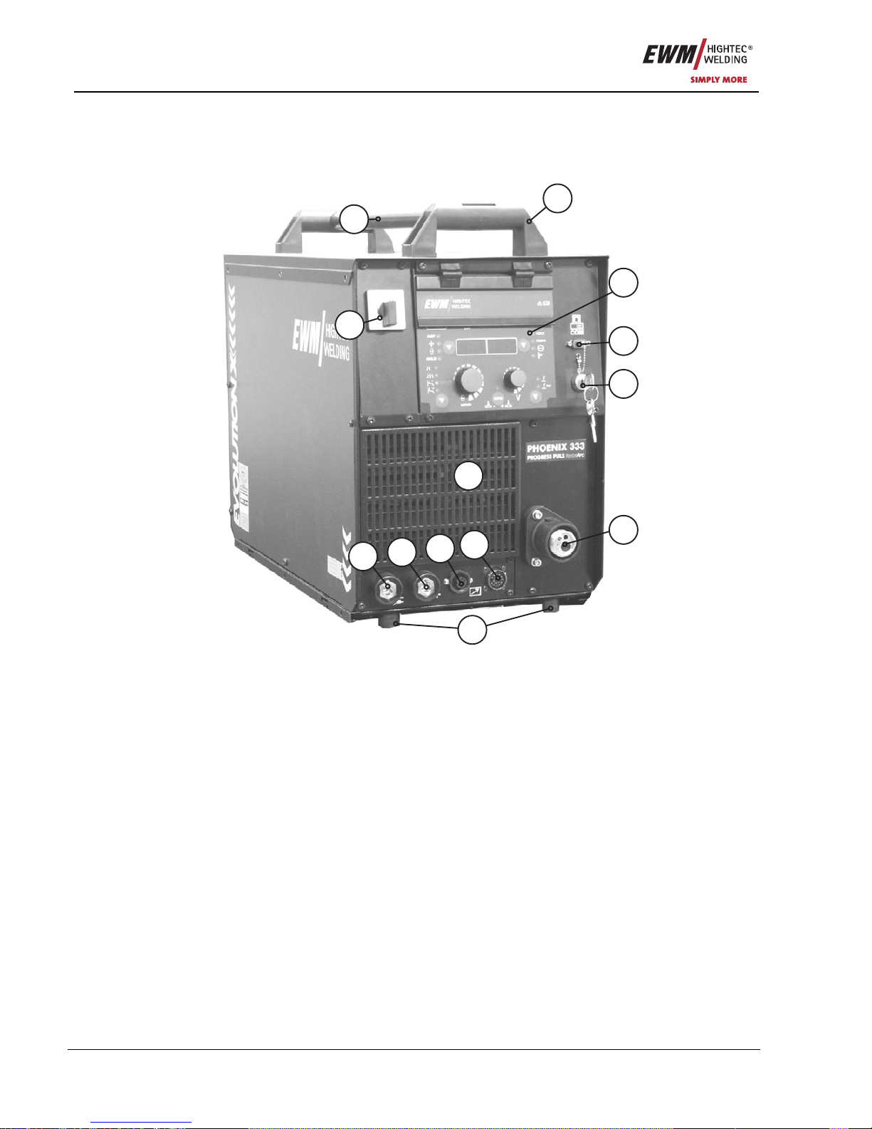
4.1.1 Front view
6
7
4
3
2
1
10
5
9
11
12
13
8
Figure 4-1
Page 15
Machine description
PHOENIX 333 PROGRESS KG
Item No.: 099-005073-EWM01 15
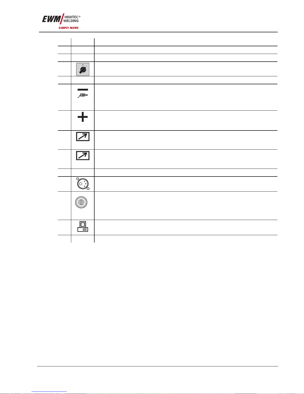
Item Symbol Description 0
1 Transport bar
2 Carrying handle
3
Main switch, machine on/off
4 Cooling air inlet
Connection socket, “-” welding current
• MIG/MAG welding: Workpiece connection
• MMA welding: Workpiece or electrode holder connection
5
• TIG welding: Welding current connection for welding torch
Connection socket, “+” welding current
• MMA welding: Workpiece or electrode holder connection
6
• TIG welding: Workpiece connection
7
7-pole connection socket (digital)
For connecting digital accessory components (remote control, wel ding torch control
lead, etc.)
8
19-pole connection socket (analogue)
For connecting analogue accessory components (remote control, welding torch control
lead, intermediate drive, etc.)
9
Rubber feet
10
Euro-central connector (welding torch connection)
Welding current, shielding gas and torch trigger included
11
0
1
Key switch for protection against unauthorised use
Position “1” > changes possible,
Position “0” > changes not possible.
Please take note of chapter “Key switch”
12
PC INT
PC interface, serial (D-SUB connection socket, 9-pole), optional
13 Control / Operating elements (see chapter Function specification)
Page 16
Machine description
PHOENIX 333 PROGRESS KG
16 Item No.: 099-005073-EWM01
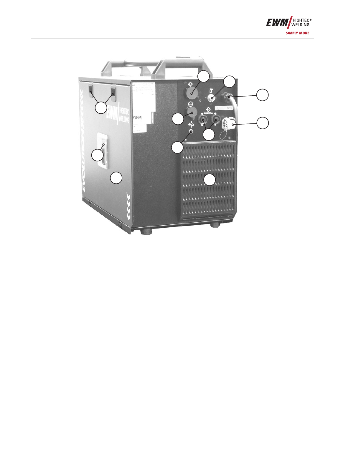
4.1.2 Rear view
6
7
4
3
2
1
10
5
9
11
8
Figure 4-2
Page 17
Machine description
PHOENIX 333 PROGRESS KG
Item No.: 099-005073-EWM01 17
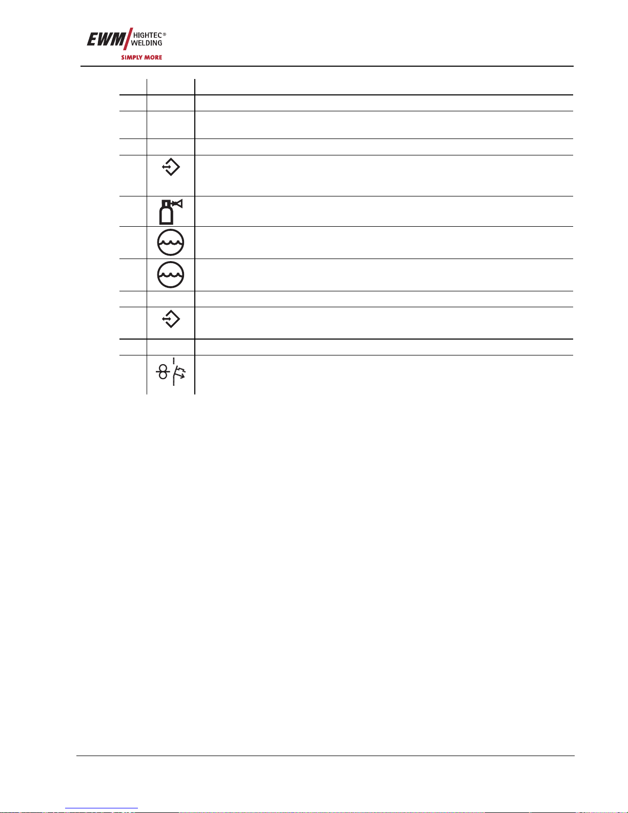
Item Symbol Description 0
1 Slide latch, lock for the protective cap
2 Wire spool inspection window
Check wire supply
3 Cover for wire delivery unit and operating elements
4
digital
7-pole connection socket (digital)
For connecting digital accessory components (documentation interface, robot interface
or remote control, etc.).
5
G¼” connecting nipple
Shielding gas connection on the pressure reducer
6
4-pole connection socket
Cooling unit voltage supply
7
8-pole connection socket
Cooling unit control lead
8 Cooling air outlet
9
analog
19-pole interface for mechanised welding (analogue), optional
(see Function specification chapter)
10 Strain relief with mains connection cable
11
42V/4A
"Automatic cutout" key button
Wire feed motor supply voltage fuse
(press to reset a triggered fuse)
Page 18
Machine description
PHOENIX 333 PROGRESS KG
18 Item No.: 099-005073-EWM01
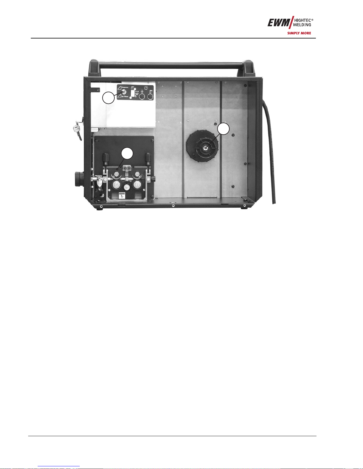
4.1.3 Inside view
2
3
1
Figure 4-3
Page 19
Machine description
PHOENIX 333 PROGRESS KG
Item No.: 099-005073-EWM01 19
Item Symbol Description 0
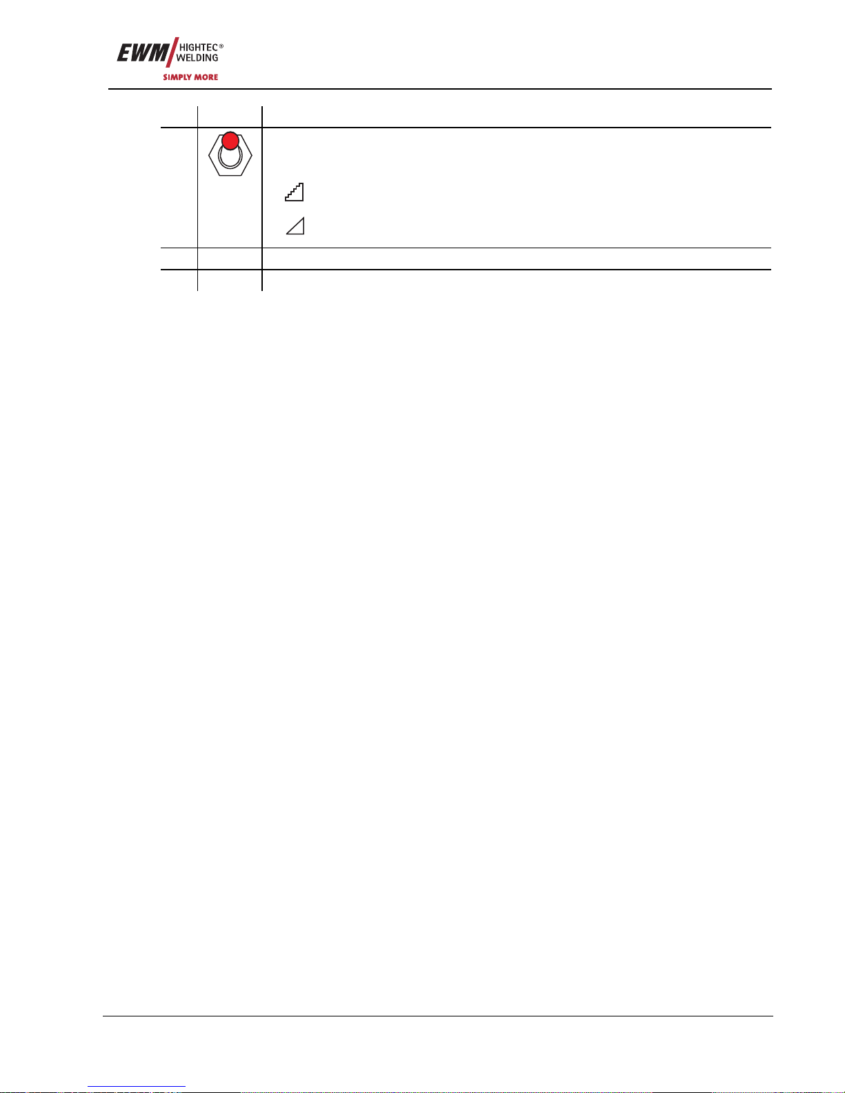
"Program or up/down function" changeover switch
This changeover switch is only effective on the POWERCONTROL/POWERCONTROL
2 welding torch
ProgrammProgramm
Change over welding programs using POWERCONTROL 2 pro gram
torch.
1
Up / Down
Set infinite welding performance with the POWERCONTROL 2
program torch, up/down function.
2 Wire delivery unit
3 Spool holder
Page 20
Functional characteristics
Machine control – Operating elements
20 Item No.: 099-005073-EWM01
5 Functional characteristics
5.1 Machine control – Operating elements
5.1.1 Welding machine control
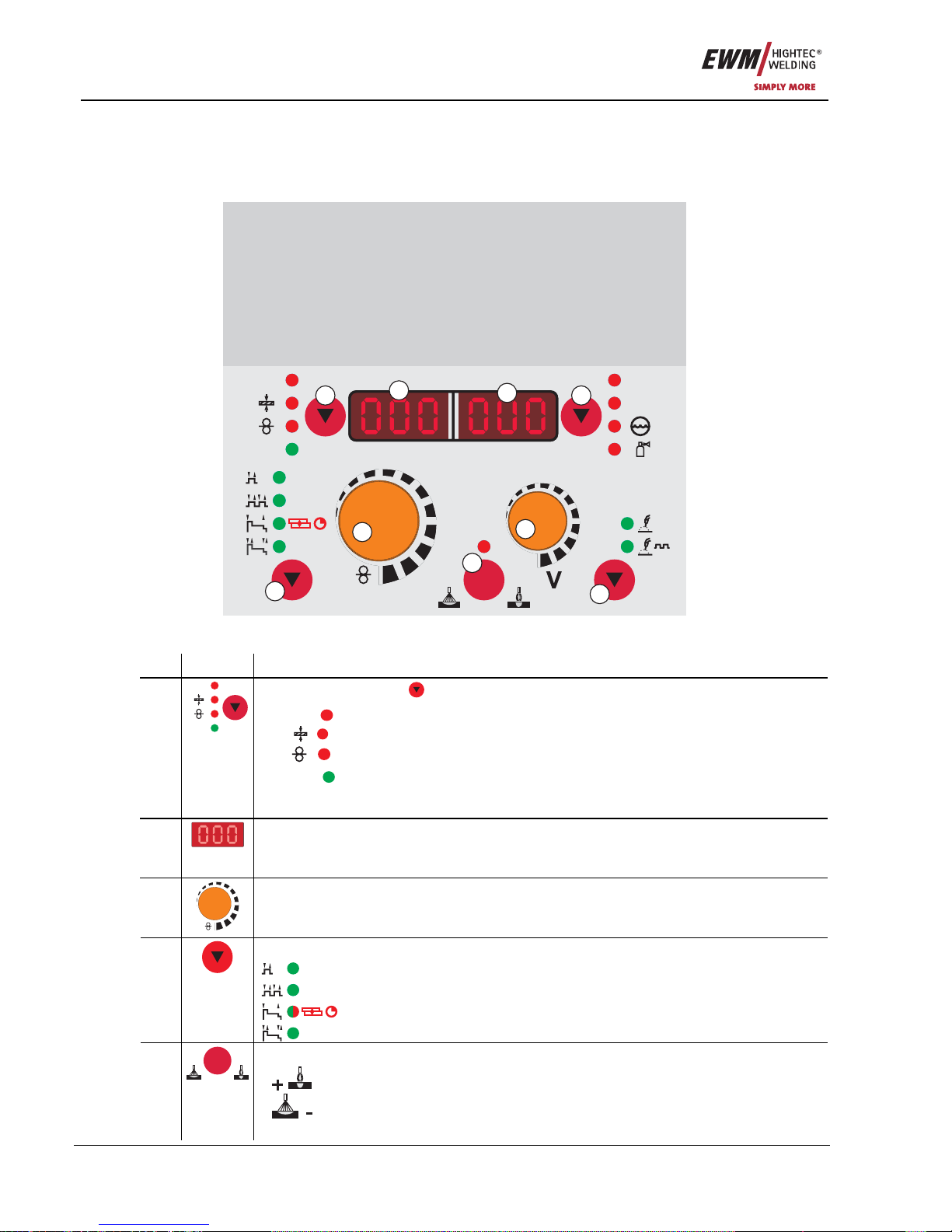
M 3.70
sec
sec
SP2
SP1
sec
sec
sec
HOLD
AMP
VOLT
PROG
sec
DYN
Super-
puls
sec
sec
SP3
S
EXPERT
m/min
DYN
- +
6
7
4
3
2
1
5
9
8
Figure 5-1
Item Symbol Description 0
“Parameter selection ” (left )
AMP
Welding current (nominal, actual and hold values)
Material thickness (nominal value)
Wire speed (actual, nominal and hold values)
1
HOLD
AMP
HOLD
After each completed welding process, the last parameter values
used for the welding process are shown on the display in the main
program; the signal light is on
2
LCD display, 3-digit (left)
Display of the parameters and values: Welding current, material thickness, wire speed,
hold values
3
m/min
"Wire speed / welding parameter setting" rotary dial
Infinitely adjustable setting of the wire speed from 0.5m/min to 24m/min (HS: 30m/min)
(welding performance, one-dial operation)
"Select operating mode" button
Non-latched
Latched
Non-latched special (LED green) / MIG spots (LED red)
4
Special latched
"Arc characteristics, choke effect" button
Arc harder and narrower
5
DYN
- +
Arc softer and wider
Page 21
Functional characteristics
Machine control – Operating elements
Item No.: 099-005073-EWM01 21
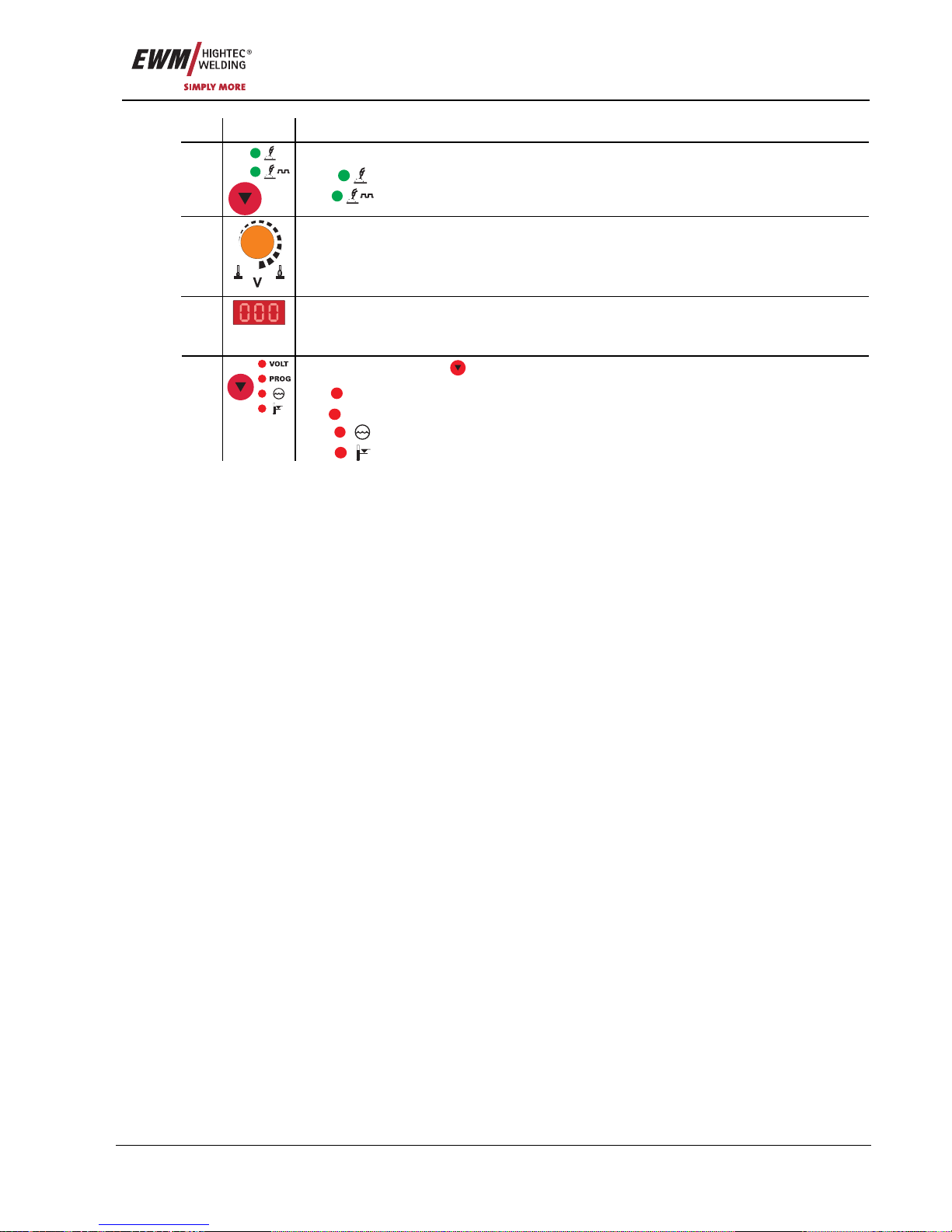
Item Symbol Description 0
"Select welding type" button
MIG/MAG standard welding
6
MIG/MAG pulse arc welding (PULS series only)
7
"Arc length correction / program number" rotary dial
• Arc length correction from -9.9 V to +9.9 V
• Setting the program number 0-15 (not possible if accessory components such as
program torches is connected)
8
LCD display, 3-digit (right)
Display of the parameters and values: Welding voltage, program number, coolant low,
temperature error
“Parameter selection ” button (right)
VOLT
Welding voltage (actual, nominal and hold values)
PROG
Program number
Coolant error
9
Temperature error
Page 22
Functional characteristics
Machine control – Operating elements
22 Item No.: 099-005073-EWM01
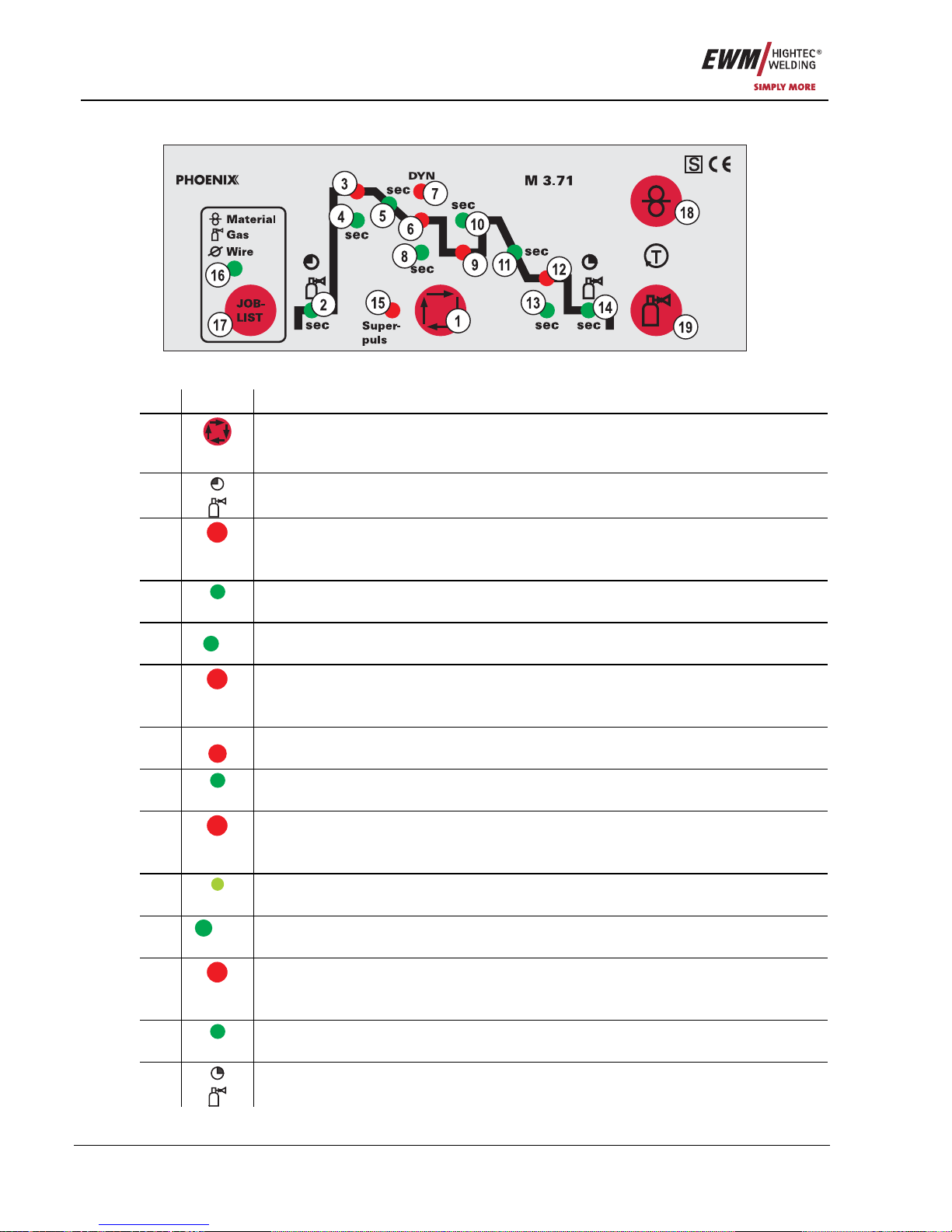
5.1.1.1 Covered operating elements
Figure 5-2
Item Symbol Description 0
1
“Select welding parameters” button
This button is used to select the welding parameters depending on the welding process
and operating mode used.
2
LED "Gas pre-flow time"
Setting range 0.0 sec to 20.0 sec
3
LED "start program (P
START
)"
• Wire speed setting range 1 % to 200 % of main program P
A
• Setting range for arc length correction -9.9 V to +9.9 V
4
sec
LED "Start time"
Absolute setting range 0.0 sec to 20.0 sec (0.1s increments).
5
sec
LED "Duration of slope from program P
START
to main program PA"
Setting range 0.0 sec to 20.0 sec (0.1s increments).
6
LED "Main program (P
A
)"
• Wire speed setting range WF-min. to WF-max.
• Setting range for arc length correction -9.9 V to +9.9 V
7
DYN
LED "Dynamics"
Setting range -40 to +40
8
sec
LED "Duration of main program P
A
"
Absolute setting range 0.0 sec to 20.0 sec (0.1s increments) for superpulse.
9
LED "Reduced main program (P
B
)"
• Wire speed setting range 1 % to 200 % of main program P
A
• Setting range for arc length correction -9.9 V to +9.9 V
10
sec
LED "Duration of reduced main program P
B
"
Absolute setting range 0.0 sec to 20.0 sec (0.1s increments) for superpulse.
11
sec
LED "Slope duration from program P
A
or PB to end program P
END
"
Setting range 0.0 sec to 20.0 sec (0.1s increments).
12
LED "End program (P
END
)"
• Wire speed setting range 1 % to 200 % of main program P
A
• Setting range for arc length correction -9.9 V to +9.9 V
13
sec
LED "Duration of end program P
END
"
Setting range 0.0 sec to 20.0 sec (0.1s increments).
14
LED "Gas post-flow time"
Setting range 0.0 sec to 20.0 sec
Page 23
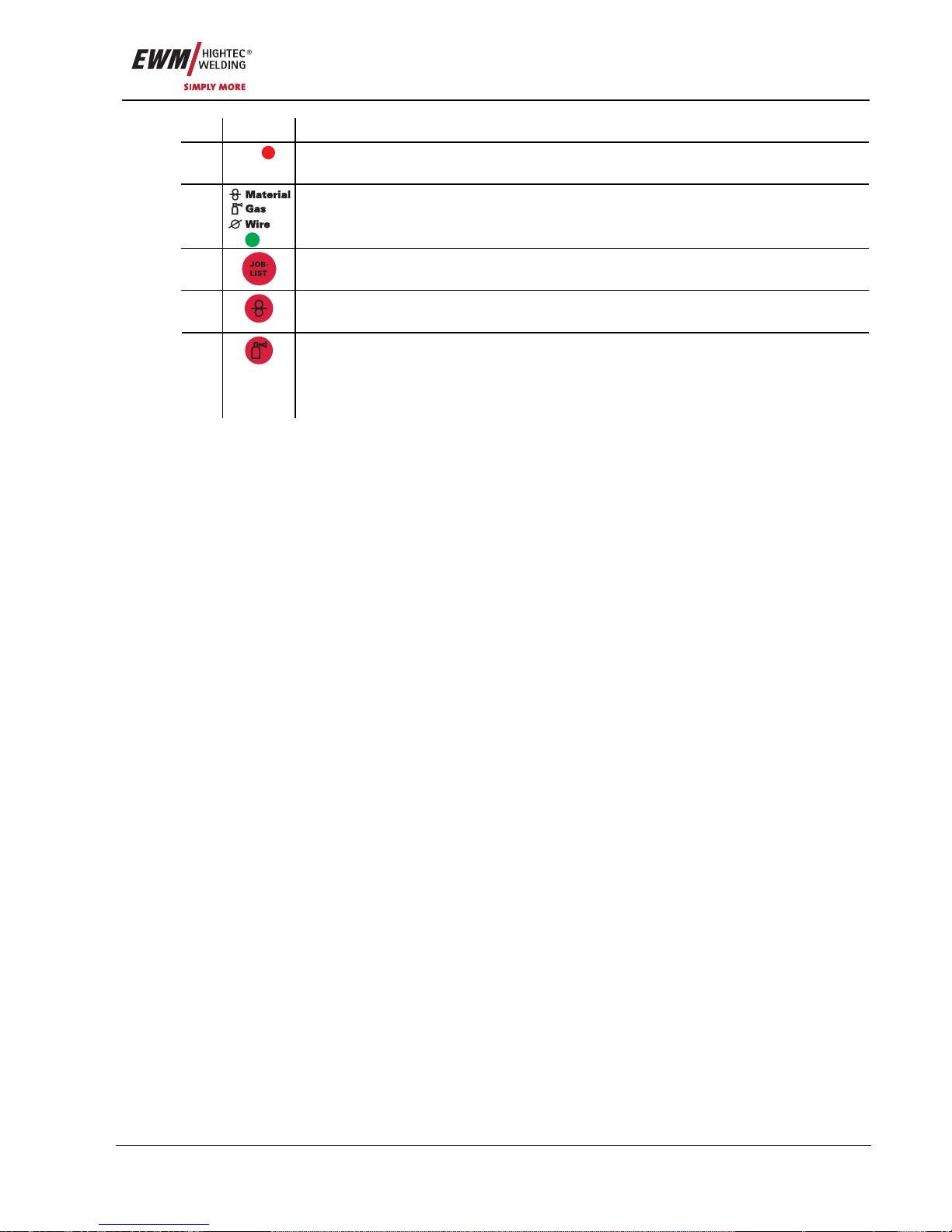
Functional characteristics
Machine control – Operating elements
Item No.: 099-005073-EWM01 23
Item Symbol Description 0
15
Superpuls
"Superpulse" LED
On when the function is activated
16
LED “Joblist”
Illuminates upon display or selection of the job number
17
“JOBLIST” key button
Selection of the welding task (JOB) from the JOB list
18
“Wire inching” button
See also “Commissioning/Inching the Wire Electrode” chapter
“Gas test / rinse” button
• Gas test: For setting the shielding gas quantity
• Rinse: For rinsing longer tube packages
19
See also "Commissioning/Shielding Gas Supply" chapter
Page 24
Functional characteristics
MIG/MAG welding
24 Item No.: 099-005073-EWM01
5.2 MIG/MAG welding
5.2.1 Definition of MIG/MAG welding tasks
The PHOENIX product range has been designed to be very simple and quick to operate, but still provide
all the functions one could ever need.
For the most common applications, 128 JOBs (welding tasks) have been pre-programmed. The JOB
(welding task) is defined using the four basic welding parameters of welding process, material type, wire
diameter and gas type.
The digital system calculates the process parameters required, such as the welding current, welding
voltage and pulse current according to the operating point specified.
All the user needs to do is select the required job number (material, wire diameter, gas combination)
using the job list (sticker on the casing cover on the wire feed unit) and enter this job number on the
machine control.
There are presets for other welding parameters such as gas pre-flow, free-burning, etc. for numerous
applications, and these can be changed if required.
The parameters and functions described here can also be programmed by PC using the PHOENIX PC
300.NET welding parameter software.
5.2.2 Selecting MIG/MAG welding tasks
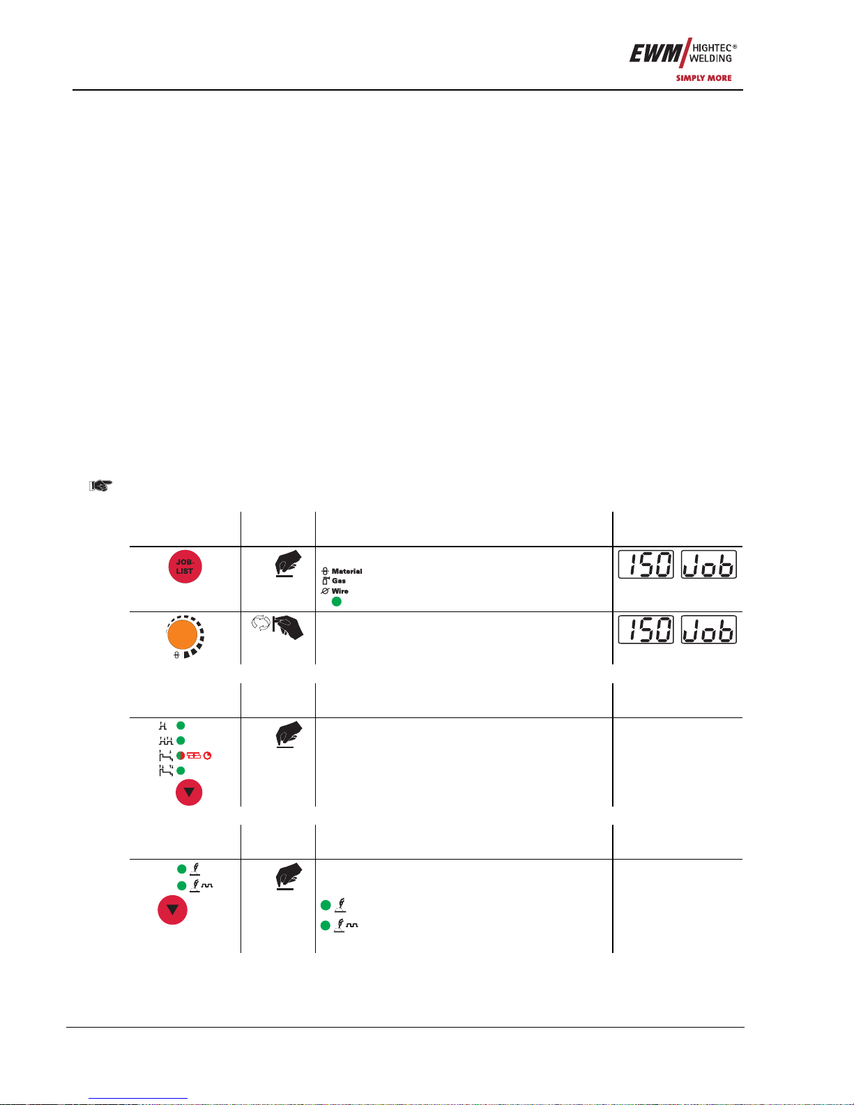
5.2.2.1 Basic welding parameters
• Select JOB (welding task) using the JOB list.
On decompact welding systems, the "JOB list" sticker is located on the inside on the wire feed unit
cover; with compact machines it is on the right-hand power source cover.
It is only possible to change the JOB number when no welding current is flowing.
Operating
element
Action Result Display
1 x
Select JOB number input
comes on
m/min
Set the JOB number
The machine adopts the required setting after
approx. 3 seconds
5.2.2.2 Operating mode
Operating
element
Action Result Display
X x
Select operating mode
The signal light displays the selection.
No change
5.2.2.3 Welding type
Operating
element
Action Result Display
X x
Select welding type
The signal light indicates the selection.
Standard MIG/MAG welding
Pulse arc MIG/MAG welding
(PULS series only)
No change
Page 25
Functional characteristics
MIG/MAG welding
Item No.: 099-005073-EWM01 25
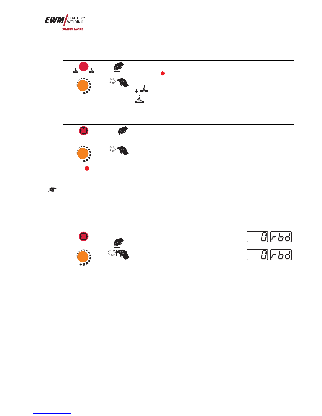
5.2.2.4 Choke effect / dynamics
Operating
element
Action Result Display
DYN
- +
Select Dynamics welding parameter
Dynamics
DYN
comes on
-40 to +40
m/min
Dynamics setting
Arc harder and narrower
Arc softer and wider
-40 to +40
5.2.2.5 Superpulses
Operating
element
Action Result Display
X x
Selects super pulses
Press the “Select welding parameters” button
until “on/off Sup” appears on the display.
on/off Sup
m/min
Switches function on or off.
on/off Sup
Superpuls
The signal light indicates when the function
has been activated.
5.2.2.6 Wire burn-back
Prevents fusing of the wire electrode in the molten pool.
Wire back-burn set too high: large drops developing on the wire electrode result in poor ignition
properties or the wire electrode sticking to the welding nozzle. Wire back-burn set too low: Wire
electrode sticks in the molten pool.
Operating
element
Action Result Display
3 sec.
Selects wire burn-back
m/min
Parameter setting
(setting range 0 to 499)
Page 26
Functional characteristics
MIG/MAG welding
26 Item No.: 099-005073-EWM01
5.2.3 MIG/MAG operating point
The operating point (welding output) is specified using the principle of MIG/MAG one-dial operation, i.e.
the user need only specify the operating point by setting the required wire speed, for example, and the
digital system will calculate the optimum values for welding current and voltage (operating point).
The operating point setting can also be specified using the accessory components such as the remote
control, welding torch, etc.
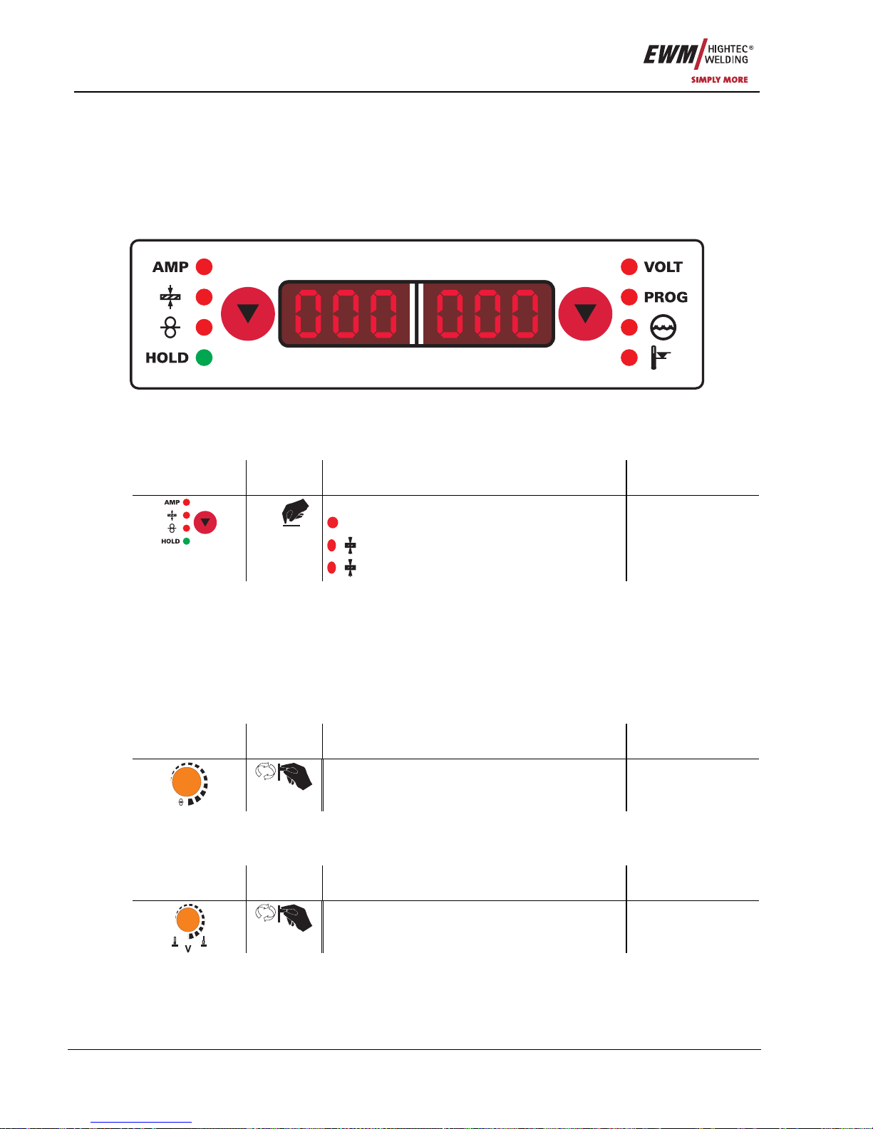
5.2.3.1 Selecting the display unit
Figure 5-3
The operating point (welding performance) can be displayed as the welding current, material thickness or
wire speed.
Operating
element
Action Result Display
X x
Switching the LCD display between:
A
Welding current
Material thickness
Wire speed
No change
Example application
You need to weld aluminium, material = AlMg, gas = Ar 100%, wire diameter = 1.2 mm (in other words,
JOB 183), you do not have any specifications and do not know the required settings, e.g. for the wire
speed.
Switch display to material thickness, set operating point to 5 mm panel thickness, for example.
This corresponds to a wire speed of 8.4 m/min.
5.2.3.2 Operating point setting using material thickness, welding current, wire speed
In the following versions, only the wire speed is given to represent the operating point setting.
Operating
element
Action Result Display
m/min
Operating point is set using the wire speed
previously set.
Selected parameter
5.2.3.3 Arc length correction setting
The “Arc length correction” setting option is provided for the individual adjustment of the arc length for any
specific welding task and any application.
Operating
element
Action Result Display
"Arc length correction" setting Selected parameter
Page 27
Functional characteristics
MIG/MAG welding
Item No.: 099-005073-EWM01 27
5.2.3.4 Wire burn-back
Operating
element
Action Result Display
3 sec.
Selects wire burn-back
m/min
Parameter setting
(setting range 0 to 499)
5.2.3.5 Accessory components for operating point setting
Accessory component Description
PHOENIX R10 remote control See "Remote controls" chapter
PHOENIX R20 remote control See "Remote controls" chapter
PHOENIX R40 remote control See Phoenix R40 operating instructions
MIG/MAG Powercontrol program torch See "MIG/MAG Powercontrol program torch"
chapter
MIG/MAG Powercontrol2 torch See Powercontrol2 torch operating instructions
PC300.Net PC software See PC300.Net operating instructions
RINT X11 robot interface,
industrial bus interface
See RINTX11 operating instructions
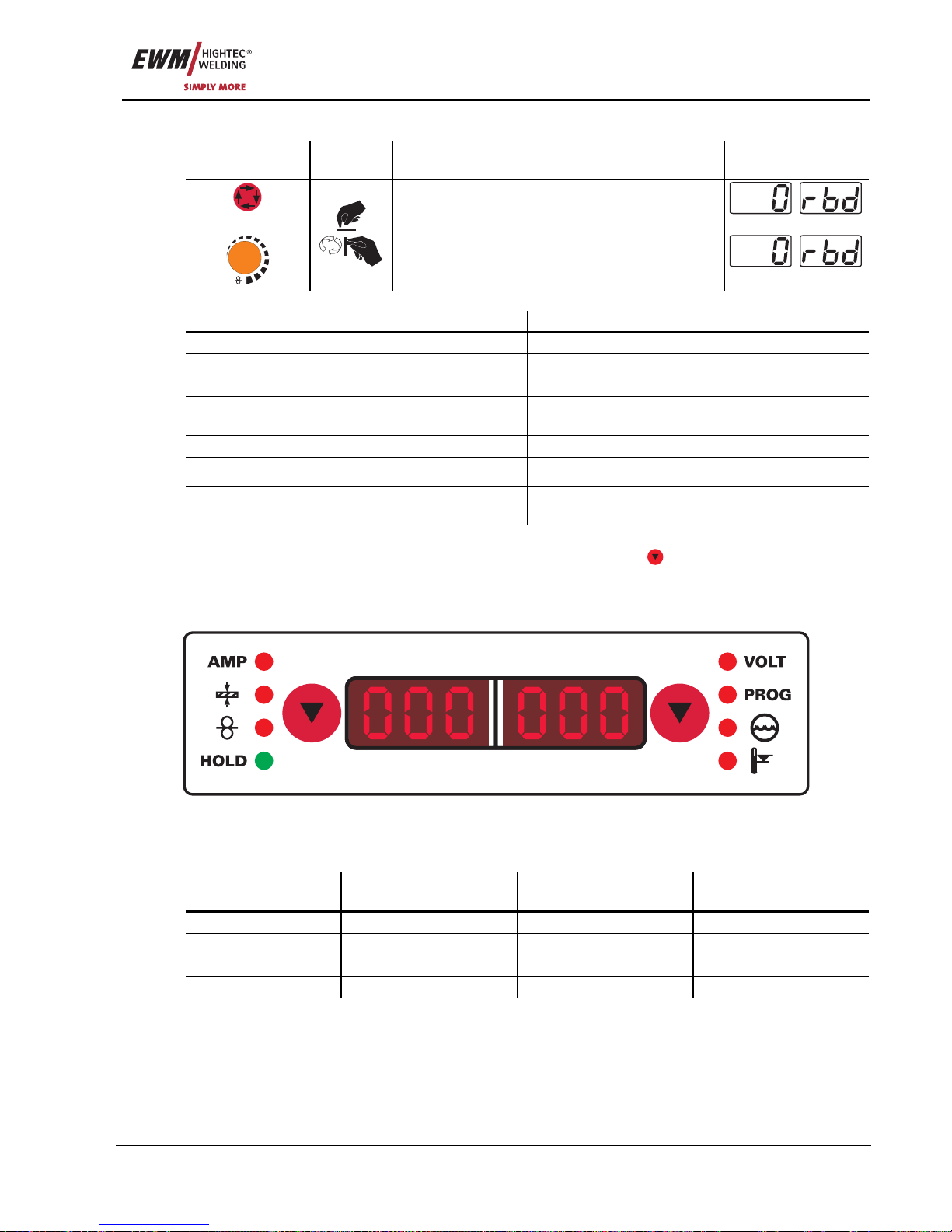
5.2.4 MIG/MAG welding data display
To the left of the LCD display on the control there is an “arrow button” ( ) for selecting the welding
parameters to be displayed. This button is used to scroll through the parameters from top to bottom.
When the last point is reached, the next parameter shown will be the top one.
The settings for the gas post-flow time, wire burn-back and hotstart current are also made in this way.
Figure 5-4
The parameters can be displayed before (nominal values), during (actual values) or after welding (hold
values; the "Hold" signal light will be on).
Parameter Before welding
(nominal values)
During welding
(actual values)
After welding (hold
values)
Welding current
z z z
Material thickness
z
Wire speed
z z z
Welding voltage
z z z
As soon as changes have been made to the settings (e.g. wire speed) after welding when the hold
values are displayed, the display will be switched to the nominal values.
Page 28
Functional characteristics
MIG/MAG welding
28 Item No.: 099-005073-EWM01
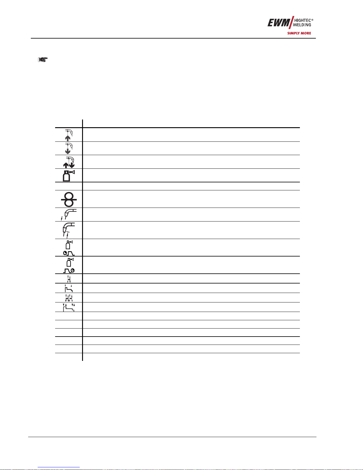
5.2.5 MIG/MAG functional sequences / operating modes
The following applies during the wire creep phase:
If there is no welding current flowing after 5 seconds (factory setting), the ignition process
is cancelled (ignition error).
The following applies during the welding phase:
If the arc is broken during the welding process and is not re-ignited within 5 seconds
(factory setting), there is an automatic cut-out.
There are optimum pre-sets for welding parameters such as gas pre-flow and free-burn, etc.
for numerous applications (although these can also be changed if required).
5.2.5.1 Explanation of signs and functions
Symbol Meaning
Press torch trigger
Release torch trigger
Tap torch trigger (press briefly and release)
Shielding gas flowing
I
Welding output
Wire electrode is being conveyed
Wire creep
Wire burn-back
Gas pre-flows
Gas post-flows
Non-latched
Special, non-latched
Latched
Special, latched
t
Time
PSTART
Ignition program
PA
Main program
PB
Reduced main program
PEND
End program
t2
Spot time
Page 29
Functional characteristics
MIG/MAG welding
Item No.: 099-005073-EWM01 29
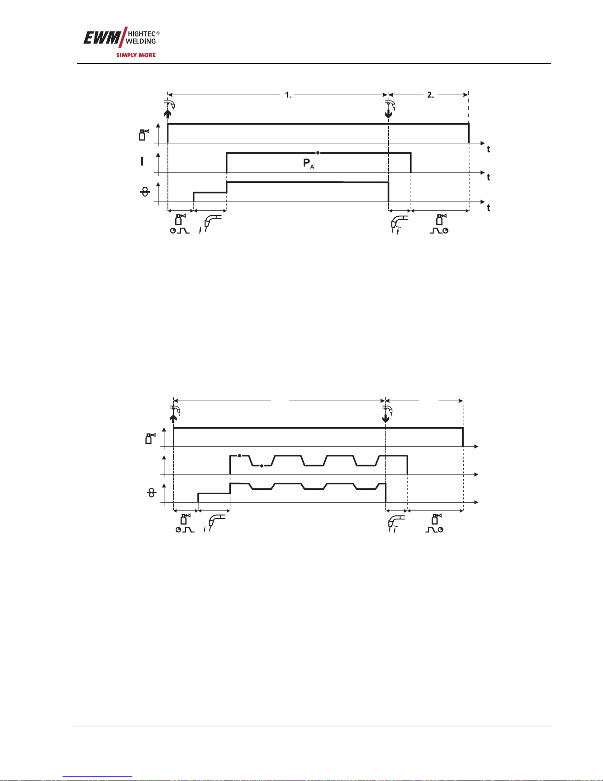
5.2.5.2 Non-latched mode
Figure 5-5
Step 1
• Press and hold torch trigger.
• Shielding gas is expelled (gas pre-flows).
• Wire feed motor runs at “creep speed”.
• Arc ignites after the wire electrode makes contact with the workpiece; welding current flows.
• Change over to pre-selected wire speed (main program P
A
).
Step 2
• Release torch trigger.
• WF motor stops.
• Arc is extinguished after the preselected wire burn-back time expires.
• Gas post-flow time elapses.
5.2.5.3 Non-latched operation with superpulse
t
I
t
t
1. 2.
P
A
P
B
Figure 5-6
Step 1
• Press and hold torch trigger.
• Shielding gas is expelled (gas pre-flows).
• Wire feed motor runs at “creep speed”.
• Arc ignites after the wire electrode makes contact with the workpiece; welding current flows.
• Start the super pulse function beginning with main program P
A
:
The welding parameters change at the specified times between main program P
A
and the reduced
main program P
B
.
Step 2
• Release torch trigger.
• Super pulse function is ended.
• WF motor stops.
• Arc is extinguished after the preselected wire burn-back time expires.
• Gas post-flow time elapses.
Page 30
Functional characteristics
MIG/MAG welding
30 Item No.: 099-005073-EWM01
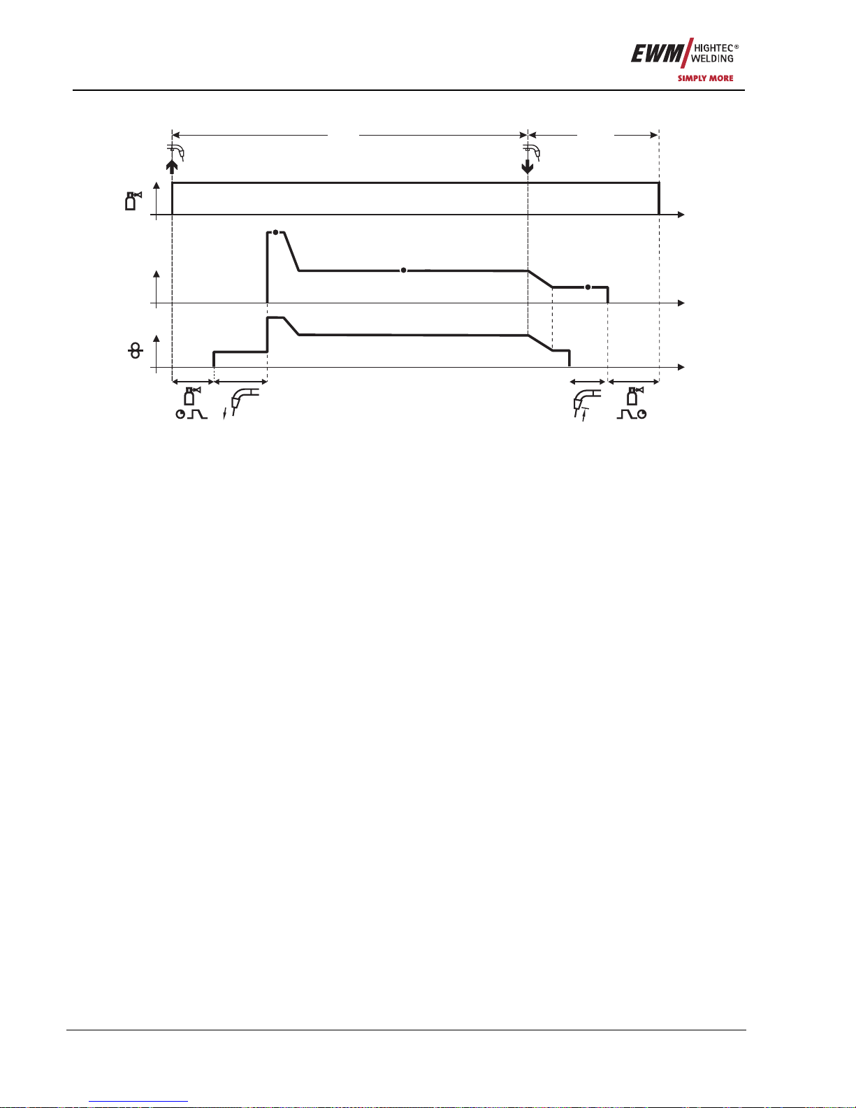
5.2.5.4 Special, non-latched
t
t
t
I
1. 2.
P
A
P
END
P
START
Figure 5-7
Step 1
• Press and hold torch trigger
• Shielding gas is expelled (gas pre-flows)
• Wire feed motor runs at “creep speed”.
• Arc ignites after the wire electrode makes contact with the workpiece, welding current is flowing (start
program P
START
for the time t
start
)
• Slope to main program P
A
.
Step 2
• Release torch trigger
• Slope to end program P
END
for the time t
end
.
• WF motor stops.
• Arc is extinguished after the preselected wire burn-back time expires.
• Gas post-flow time elapses.
Page 31
Functional characteristics
MIG/MAG welding
Item No.: 099-005073-EWM01 31
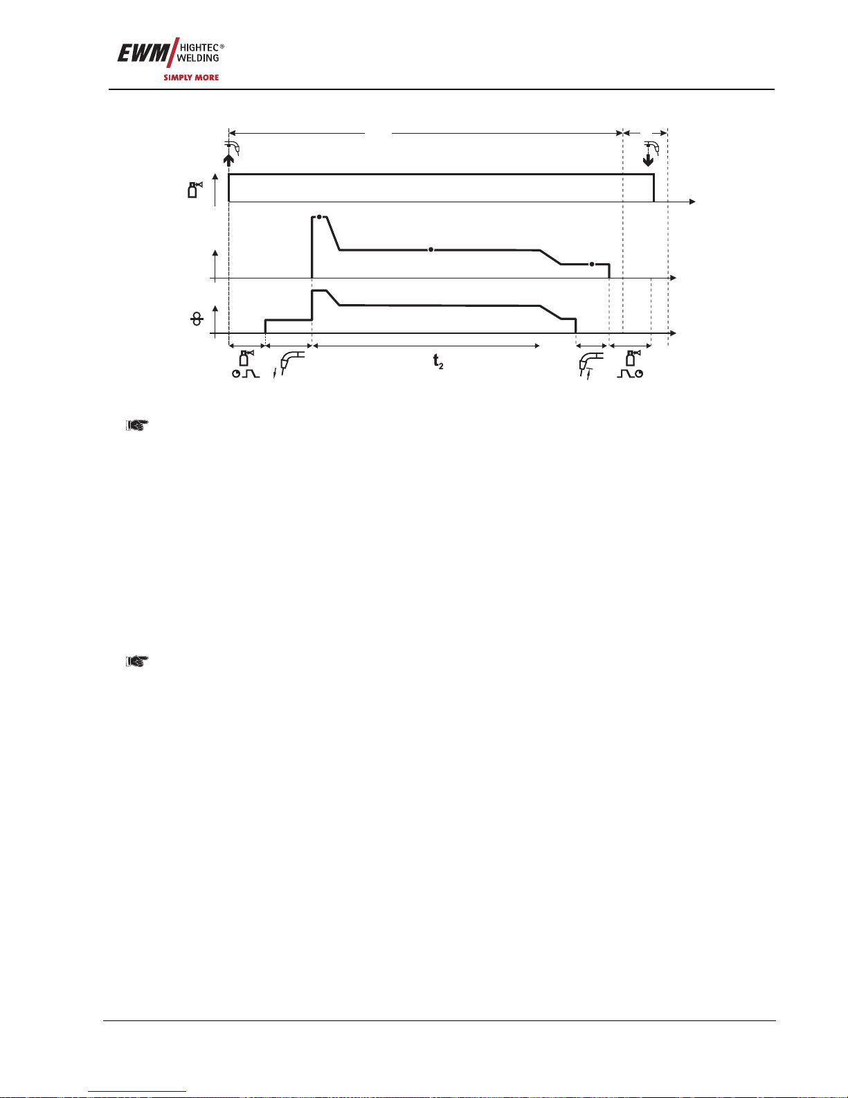
5.2.5.5 Spots
t
t
t
I
1. 2.
P
A
P
END
P
START
Figure 5-8
The start time t
start
must also be calculated at spot time t2. The start and spot times are set in
the "Program steps mode" menu.
Step 1
• Press and hold torch trigger.
• Shielding gas is expelled (gas pre-flows).
• Wire feed motor runs at "creep speed".
• Arc ignites after the wire electrode makes contact with the workpiece, welding current is flowing (start
program P
START
, spot time starts).
• Slope on main program P
A
.
• After the set spot time elapses, slope goes to end program P
END
.
• WF motor stops.
• Arc is extinguished after the pre-selected wire burn-back time elapses.
• Gas post-flow time elapses.
Step 2
• Release torch trigger
Releasing the torch trigger (step 2) interrupts the welding process even if the spot time has
not yet elapsed (slope to end program P
END
).
Page 32
Functional characteristics
MIG/MAG welding
32 Item No.: 099-005073-EWM01
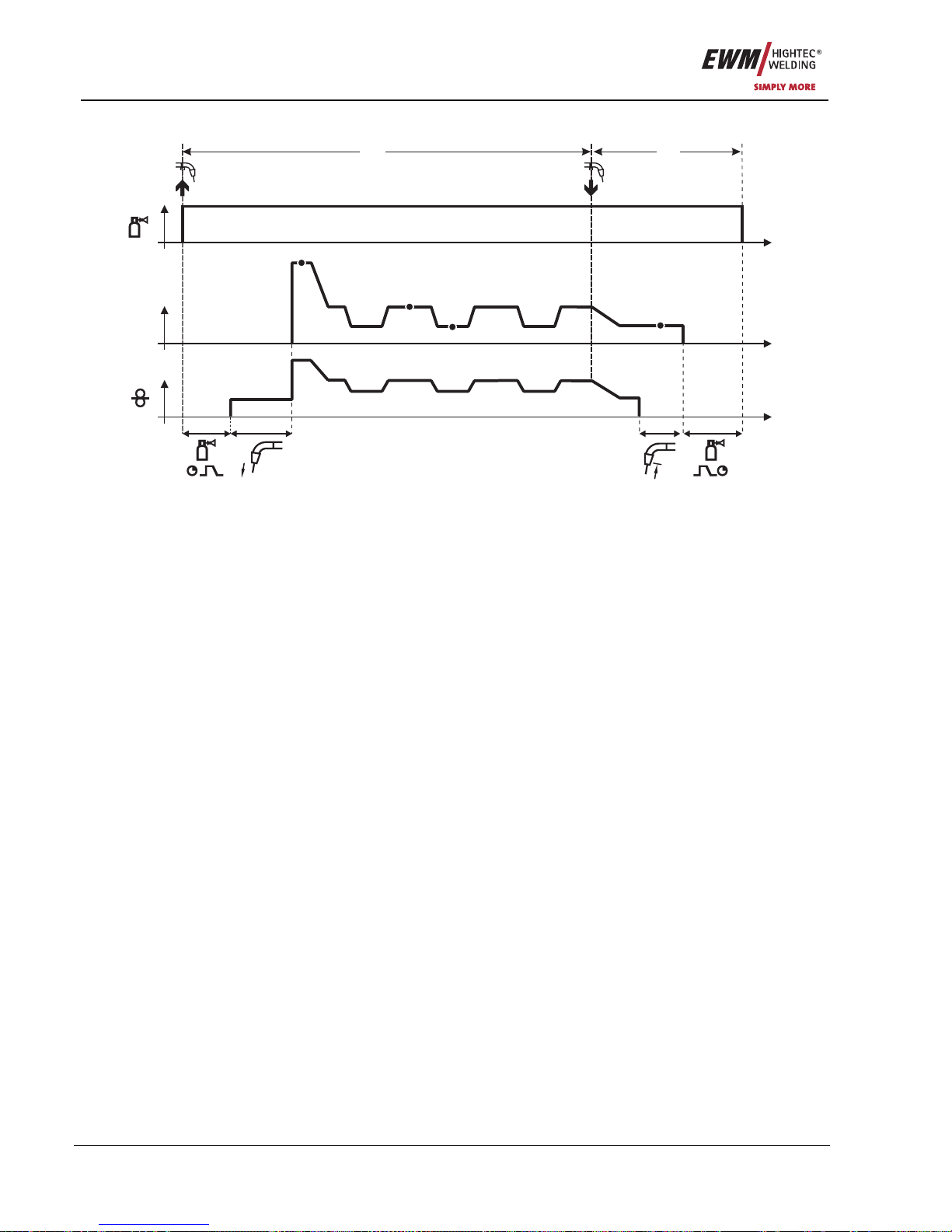
5.2.5.6 Special, non-latched with superpulse
t
t
t
I
1. 2.
P
A
P
B
P
END
P
START
Figure 5-9
Step 1
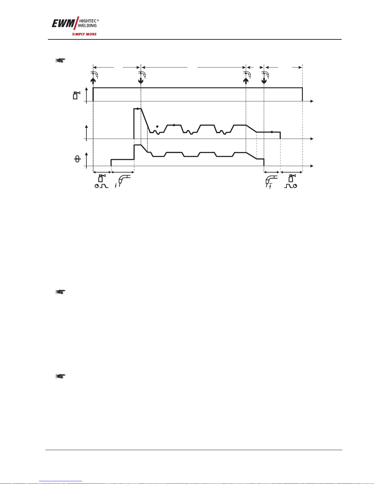
• Press and hold torch trigger
• Shielding gas is expelled (gas pre-flows)
• Wire feed motor runs at “creep speed”.
• Arc ignites after the wire electrode makes contact with the workpiece, welding current is flowing (start
program P
START
for the time t
start
).
• Slope on main program P
A
.
• Start the super pulse function beginning with main program P
A
:
The welding parameters change at the specified times between main program P
A
and the reduced
main program P
B
.
Step 2
• Release torch trigger
• Super pulse function is ended.
• Slope to end program P
END
for the time t
end
.
• WF motor stops.
• Arc is extinguished after the preselected wire burn-back time expires.
• Gas post-flow time elapses.
Page 33
Functional characteristics
MIG/MAG welding
Item No.: 099-005073-EWM01 33
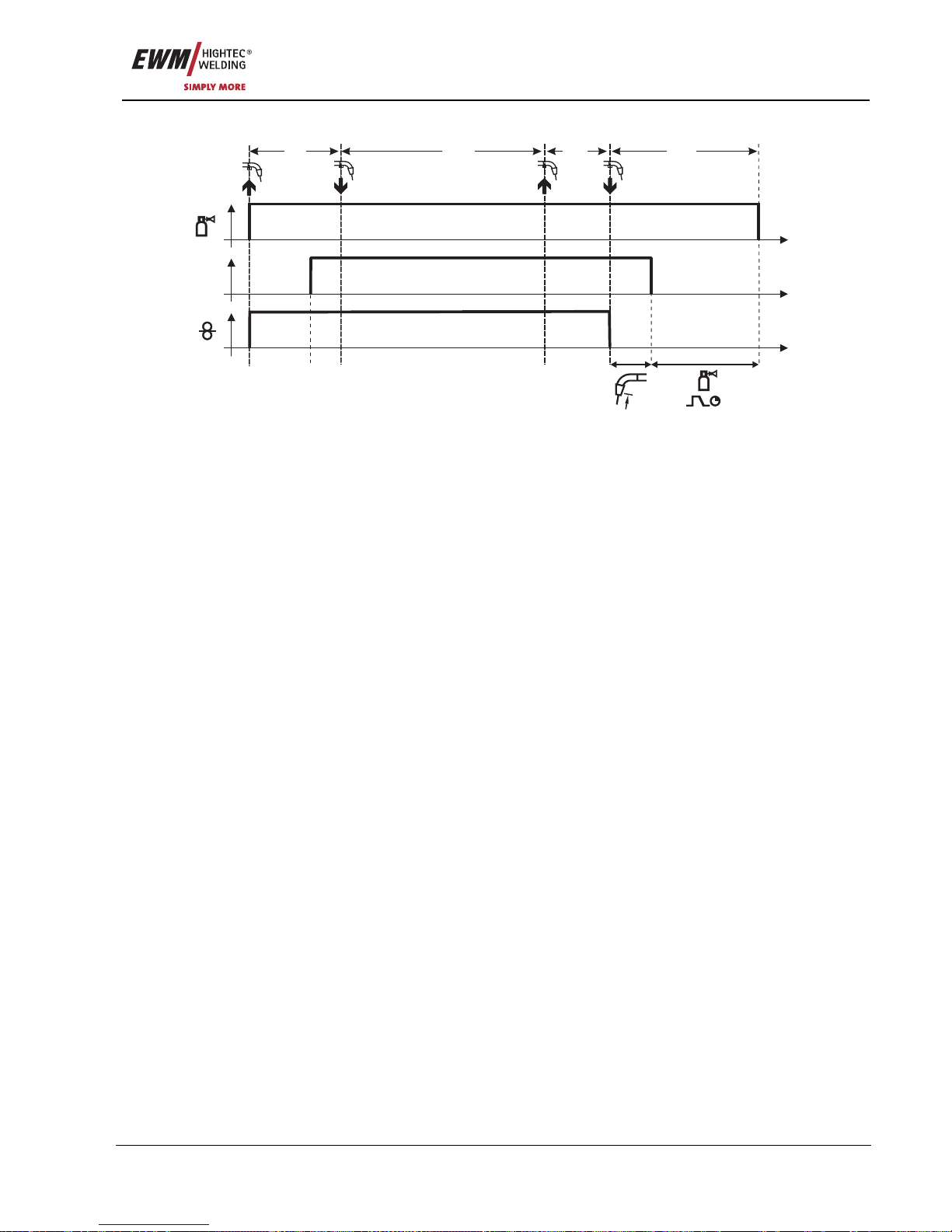
5.2.5.7 Latched mode
t
t
t
I
1.
2. 3.
4.
Figure 5-10
Step 1
• Press and hold torch trigger
• Shielding gas is expelled (gas pre-flows)
• Wire feed motor runs at “creep speed”.
• Arc ignites after the wire electrode makes contact with the workpiece; welding current flows.
• Change over to pre-selected WF speed (main program P
A
).
Step 2
• Release torch trigger (no effect)
Step 3
• Press torch trigger (no effect)
Step 4
• Release torch trigger
• WF motor stops.
• Arc is extinguished after the preselected wire burn-back time expires.
• Gas post-flow time elapses.
Page 34
Functional characteristics
MIG/MAG welding
34 Item No.: 099-005073-EWM01
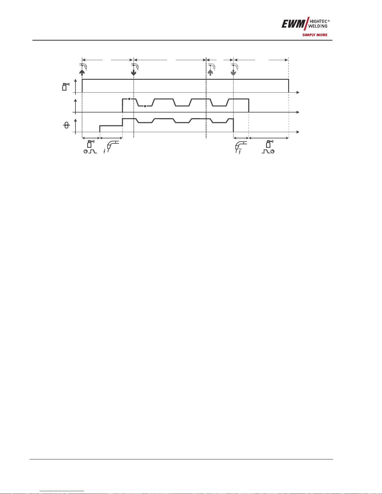
5.2.5.8 Latched mode with superpulse
t
t
t
I
1. 2. 3. 4.
P
A
P
B
Figure 5-11
Step 1:
• Press and hold torch trigger
• Shielding gas is expelled (gas pre-flows)
• Wire feed motor runs at “creep speed”.
• Arc ignites after the wire electrode makes contact with the workpiece; welding current flows.
• Start the super pulse function beginning with main program P
A
.
The welding parameters change at the specified times between main program P
A
and the reduced
main program P
B
.
Step 2:
• Release torch trigger (no effect)
Step 3:
• Press torch trigger (no effect)
Step 4:
• Release torch trigger
• Super pulse function is ended.
• WF motor stops.
• Arc is extinguished after the preselected wire burn-back time expires.
• Gas post-flow time elapses.
Page 35
Functional characteristics
MIG/MAG welding
Item No.: 099-005073-EWM01 35
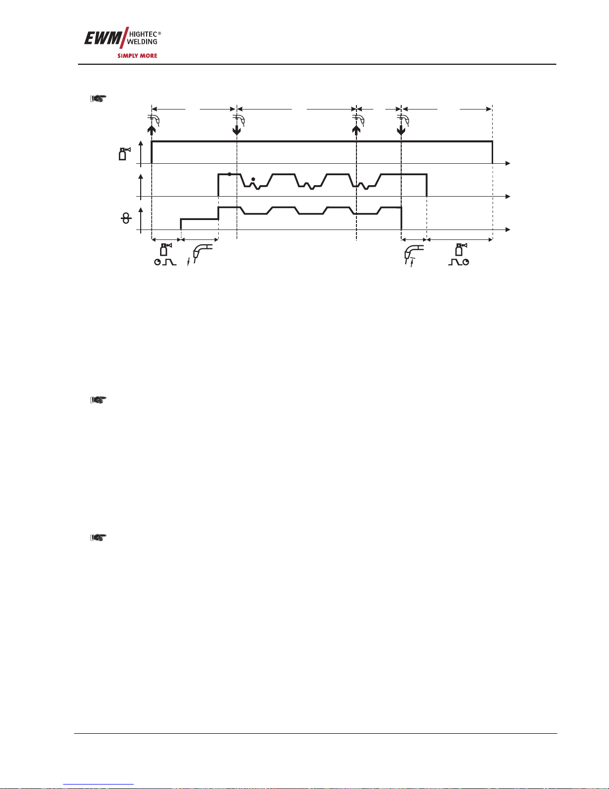
5.2.5.9 Latched mode with alternating welding process
Pulse arc welding machines only.
t
t
t
I
1. 2. 3. 4.
P
A
P
B
Figure 5-12
1st cycle:
• Press and hold torch trigger
• Shielding gas is expelled (gas pre-flows)
• Wire feed motor runs at "creep speed"
• Arc ignites after the wire electrode makes contact with the workpiece; welding current flows
• Start the process alternation starting with process P
A
:
The welding processes alternate between the process P
A
stored in the JOB and the opposite process
P
B
at the specified times (t2 and t3)
2nd cycle:
If a standard process is stored in the JOB, this means that there is a permanent alternation
between the processes, starting with the standard process and followed by the pulse process.
The same applies if the situation is reversed.
• Release torch trigger (no effect)
3
rd
cycle:
• Press torch trigger (no effect)
4
th
cycle:
• Release torch trigger
• Super pulse function is ended
• WF motor stops
• Arc is extinguished after the pre-selected wire burn-back time elapses
• Gas post-flow time elapses
This function can be activated using the PC300.Net software.
Refer to the software operating instructions.
Page 36
Functional characteristics
MIG/MAG welding
36 Item No.: 099-005073-EWM01
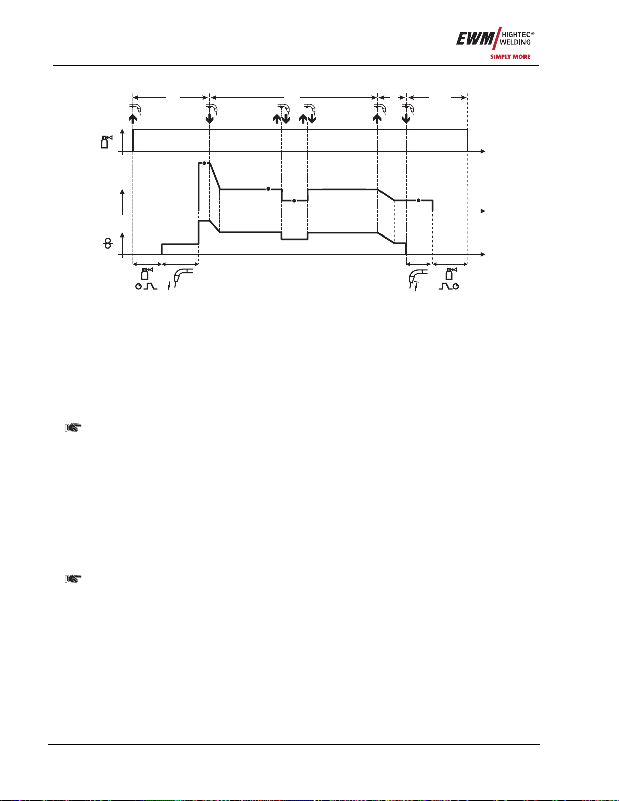
5.2.5.10 Latched special
t
t
t
I
1. 2. 3. 4.
P
A
P
B
P
END
P
START
Figure 5-13
Step 1
• Press and hold torch trigger
• Shielding gas is expelled (gas pre-flows)
• Wire feed motor runs at “creep speed”.
• Arc ignites after the wire electrode makes contact with the workpiece, welding current is flowing (start
program P
START
)
Step 2
• Release torch trigger
• Slope to main program P
A
.
The slope on main program P
A
is given at the earliest after the set time t
START
elapses and at
the latest when the torch trigger is released.
Tapping
1)
can be used to change over to the reduced main program PB.
Repeated tapping will switch back to the main program P
A
.
Step 3
• Press and hold torch trigger
• Slope to end program P
END
.
Step 4
• Release torch trigger
• WF motor stops.
• Arc is extinguished after the preselected wire burn-back time expires.
• Gas post-flow time elapses.
1)
Prevent tapping (brief press and release within 0.3 seconds)
If the welding current is to be prevented from switching over to the reduced main program
P
B
by tapping, the parameter value for WF3 needs to be set to 100% (PA = PB) in the program
sequence.
Page 37
Functional characteristics
MIG/MAG welding
Item No.: 099-005073-EWM01 37
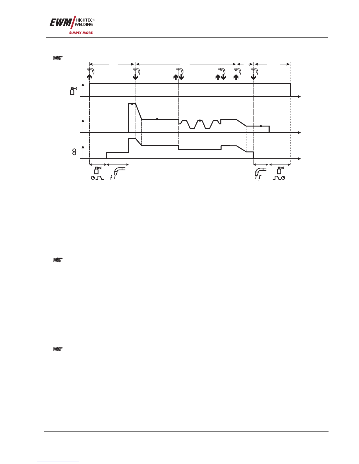
5.2.5.11 Latched special with welding process alternation
Pulse arc welding machines only.
t
t
t
I
1. 2. 3. 4.
P
A
P
B
P
END
P
START
Figure 5-14
1st cycle
• Press and hold torch trigger.
• Shielding gas is expelled (gas pre-flows)
• Wire feed motor runs at "creep speed"
• Arc ignites after the wire electrode makes contact with the workpiece, welding current is flowing (start
program P
START
)
2nd cycle
• Release torch trigger
• Slope on main program P
A
The slope on main program P
A
is given at the earliest after the set time t
START
elapses and at the
latest when the torch trigger is released.
Tapping (pressing the torch trigger for less than 0.3 sec.) changes over the welding process (P
B
).
If a standard process has been defined in the main program, tapping changes to the pulse
process, and tapping again will return to the standard process, etc.
3
rd
cycle
• Press and hold torch trigger
• Slope to end program P
END
4th cycle
• Release torch trigger
• WF motor stops
• Arc is extinguished after the pre-selected wire burn-back time elapses
• Gas post-flow time elapses
This function can be activated using the PC300.Net software.
Refer to the software operating instructions.
Page 38
Functional characteristics
MIG/MAG welding
38 Item No.: 099-005073-EWM01
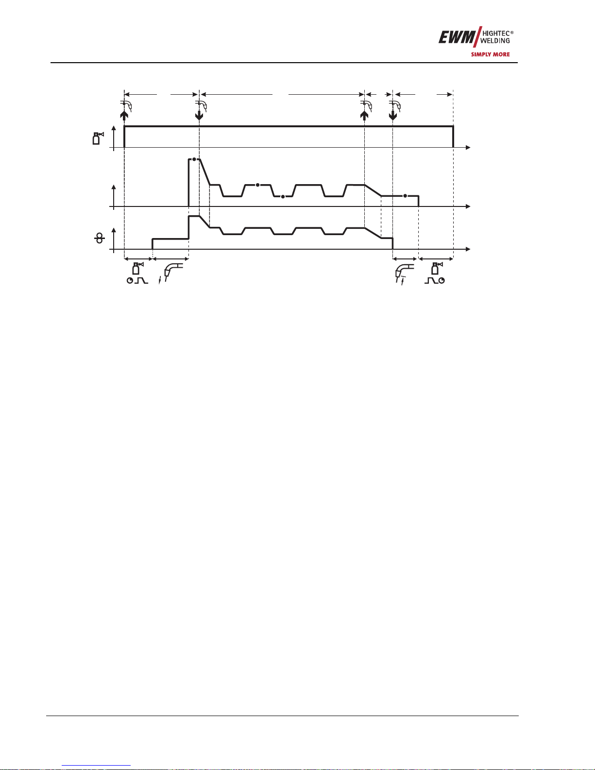
5.2.5.12 Special, latched with superpulse
t
t
t
I
1. 2. 3. 4.
P
A
P
B
P
END
P
START
Figure 5-15
Step 1
• Press and hold torch trigger
• Shielding gas is expelled (gas pre-flows)
• Wire feed motor runs at “creep speed”.
• Arc ignites after the wire electrode makes contact with the workpiece, welding current is flowing (start
program P
START
for the time t
start
).
Step 2
• Release torch trigger
• Slope on main program P
A
.
• Start the super pulse function beginning with main program P
A
:
The welding parameters change at the specified times between main program P
A
and the reduced
main program P
B
.
Step 3
• Press the torch trigger.
• Super pulse function is ended.
• Slope in the end program P
END
for the time t
end
.
Step 4
• Release torch trigger
• WF motor stops.
• Arc is extinguished after the preselected wire burn-back time expires.
• Gas post-flow time elapses.
Page 39
Functional characteristics
MIG/MAG welding
Item No.: 099-005073-EWM01 39
5.2.5.13 Latched special with alternating welding process
Pulse arc welding machines only.
t
t
t
I
1. 2. 3. 4.
P
A
P
B
P
END
P
START
Figure 5-16
1st cycle
• Press and hold torch trigger
• Shielding gas is expelled (gas pre-flows)
• Wire feed motor runs at "creep speed"
• Arc ignites after the wire electrode makes contact with the workpiece, welding current is flowing (start
program P
START
for the time t
start
)
2nd cycle
• Release torch trigger
• Slope on main program P
A
• Start the process alternation starting with process P
A
:
The welding processes alternate between the process P
A
stored in the JOB and the opposite process
P
B
at the specified times (t2 and t3)
If a standard process is stored in the JOB, this means that there is a permanent alternation
between the processes, starting with the standard process and followed by the pulse process.
The same applies if the situation is reversed.
3
rd
cycle
• Press the torch trigger
• Super pulse function is ended
• Slope in the end program P
END
for the time t
end
4th cycle
• Release torch trigger
• WF motor stops
• Arc is extinguished after the pre-selected wire burn-back time elapses
• Gas post-flow time elapses
This function can be activated using the PC300.Net software.
Refer to the software operating instructions.
Page 40
Functional characteristics
MIG/MAG welding
40 Item No.: 099-005073-EWM01
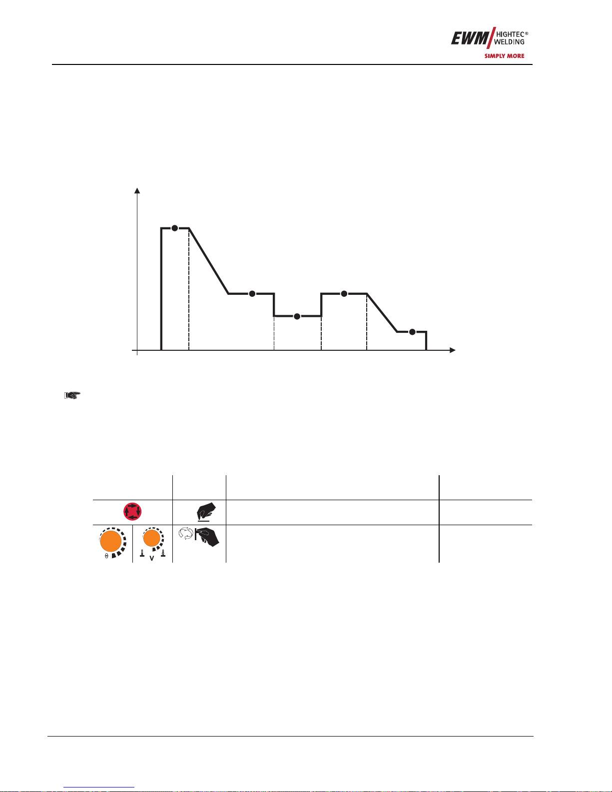
5.2.6 MIG/MAG program sequence ("Program steps" mode)
Certain materials, such as aluminium, require special functions in order to be able to weld them safely
and at high quality. The latched special operating mode is used here with the following programs:
• Start program P
START
(reduction of cool points at the start of the seam)
• Main program P
A
(continuous welding)
• Reduced main program P
B
(targeted heat reduction)
• End program P
END)
(minimisation of end craters via targeted heat reduction)
The programs include the parameters wire speed (operating point), arc length correction, slope times,
program duration, etc.
t
I
P
START
P
A
P
B
P
A
P
END
Figure 5-17
Pulse arc welding machines:
In every JOB, separate settings can be made for the ignition program, reduced main program and end
program as to whether or not to alternate with the pulse process.
These properties are stored on the welding machine with the JOB. This means that in the factory settings,
the pulse process is active during the end program in all forceArc JOBs.
Settings relating to this can be changed using the PC300.Net software.
5.2.6.1 Selecting the program sequence parameters using wire feed unit control M3.70
Operating
Element
Action Result Display
x x
Select parameter in the program sequence
m/min
Setting welding parameters
Page 41
Functional characteristics
MIG/MAG welding
Item No.: 099-005073-EWM01 41
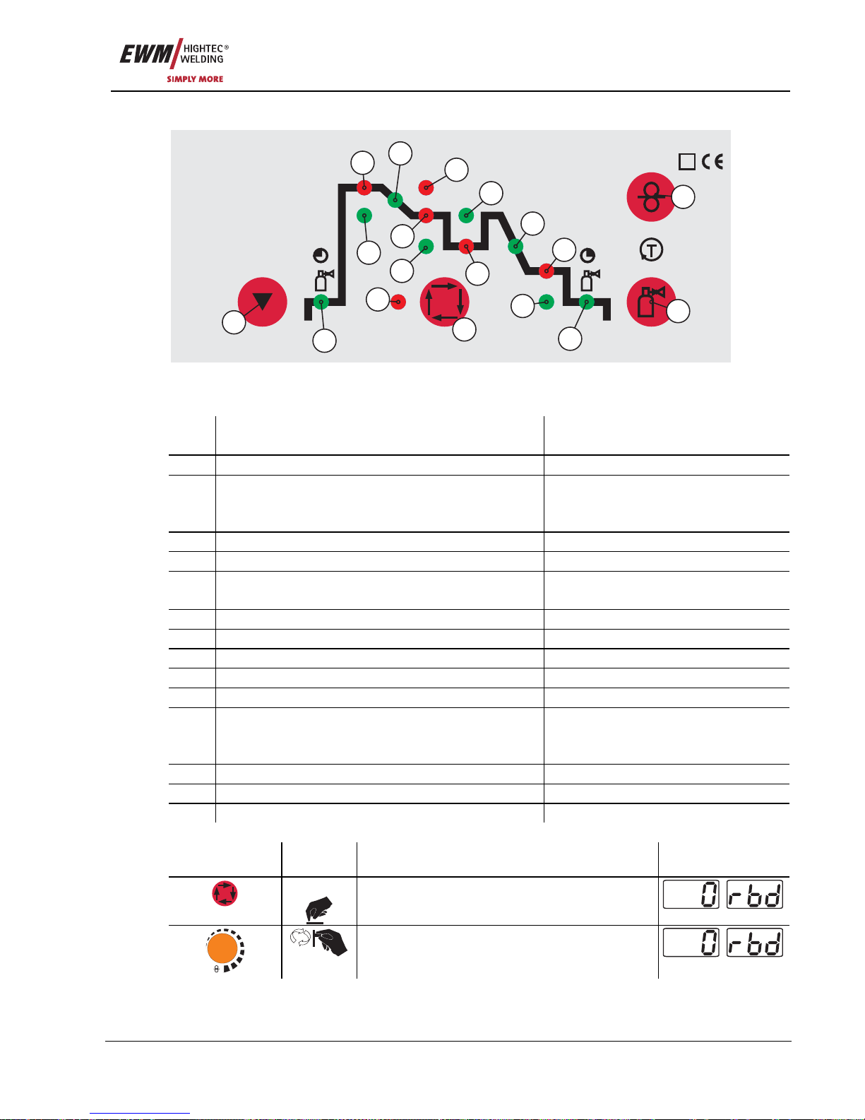
5.2.6.2 MIG/MAG overview of parameters, M3.70
sec
sec
sec
sec
sec
sec
DYN
Superpuls
sec
sec
S
6
7
4
3
2
1
18
17
10
5
9
14
11
12
15
16
8
13
Figure 5-18
Basic Parameters
Item Meaning / Explanation Setting Range
1 Gas pre-flow time 0.0s to 20.0s
2 Wire speed, relative
Wire speed, absolute
Arc length correction
1% to 200%
0.1 m/min to 40 m/min
-9.9V to +9.9V
3 Duration 0.0s to 20.0s
4 Slope duration from P
START
to PA 0.0s to 20.0s
5 Wire speed, relative
Wire speed, absolute
1% to 200%
0.1 m/min to 40 m/min
6 Dynamics -40 to +40
7 Duration (spot time and superpulse) 0.01s to 20.0s
8 Arc length correction -9.9V to +9.9V
9 Duration 0.01s to 20.0s
10 Slope duration from PA to P
END
0.0s to 20s
11 Wire speed, relative
Wire speed, absolute
Arc length correction
1% to 200%
0.1 m/min to 40 m/min
-9.9V to +9.9V
12 Duration (superpulse) 0.0s to 20s
13 Gas post-flow time 0.0s to 20s
14 Superpulses On / Off
Operating
element
Action Result Display
3 sec.
Selects wire burn-back
m/min
Parameter setting
(setting range 0 to 499)
Page 42
Functional characteristics
MIG/MAG welding
42 Item No.: 099-005073-EWM01
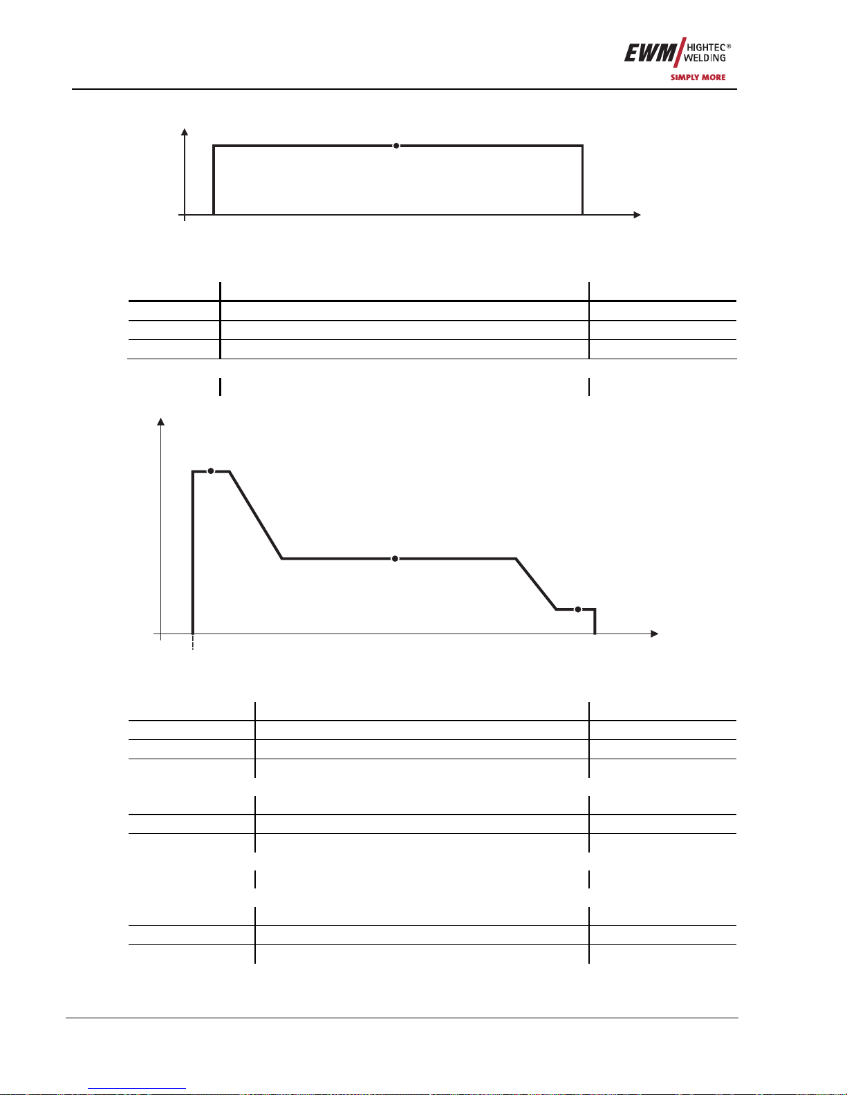
5.2.6.3 Example, tack welding (non-latched)
t
I
P
A
Figure 5-19
Basic parameters
Parameter Meaning / explanation Setting range
GASstr Gas pre-flow time 0.0s to 20.0s
GASend: Gas post-flow time 0.0s to 20s
RUECK Wire burn-back length 2 to 500
"PA" main program
Setting the wire speed
5.2.6.4 Example, aluminium tack welding (non-latched special)
t
I
P
A
P
END
P
START
Figure 5-20
Basic parameters
Welding parameter Meaning / explanation Setting range
GASstr Gas pre-flow time 0.0s to 20.0s
GASend: Gas post-flow time 0.0s to 20.0s
RUECK Wire burn-back length 2 to 500
"P
START
" start program
DVstart Wire speed 0% to 200%
ustart Arc length correction -9.9V to +9.9V
tstart Duration 0.0s to 20s
"PA" main program
Setting the wire speed
"P
END
" end-crater program
DVend Wire speed 0% to 200%
Uend Arc length correction -9.9V to +9.9V
tend Duration 0.0s to 20s
Page 43
Functional characteristics
MIG/MAG welding
Item No.: 099-005073-EWM01 43
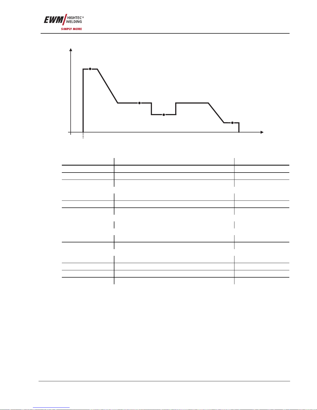
5.2.6.5 Example, aluminium welding (latched special)
t
I
P
A
P
B
P
END
P
START
Figure 5-21
Basic parameters
Welding parameter Meaning / explanation Setting range
GASstr Gas pre-flow time 0.0s to 20.0s
GASend: Gas post-flow time 0.0s to 20.0s
RUECK Wire burn-back length 2 to 500
"P
START
" start program
DVstart Wire speed 0% to 200%
ustart Arc length correction -9.9V to +9.9V
tstart Duration 0.0s to 20s
"PA" main program
Setting the wire speed
"PB" reduced main program
DV3 Wire speed 0% to 200%
U3 Arc length correction -9.9V to +9.9V
"P
END
" end-crater program
tSend Slope duration from P
A
or PB to P
END
0.0s to 20s
DVend Wire speed 0% to 200%
Uend Arc length correction -9.9V to +9.9V
tend Duration 0.0s to 20s
Page 44
Functional characteristics
MIG/MAG welding
44 Item No.: 099-005073-EWM01
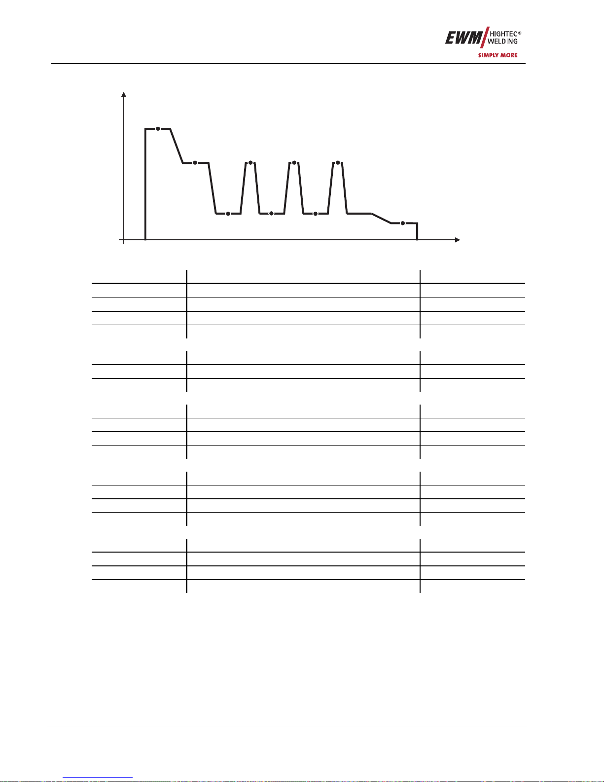
5.2.6.6 Example, visible seams (latched super pulse)
t
I
P
A
P
A
P
A
P
A
P
B
P
B
P
B
P
END
P
START
Basic parameters
Welding parameter Meaning / explanation Setting range
GASstr Gas pre-flow time 0.0s to 20.0s
GASend: Gas post-flow time 0.0s to 20.0s
RUECK Wire burn-back length 2 to 500
PROC.SP. Travel speed to determine the a-measurement* 10cm to 200cm
"P
START
" start program
DVstart Wire speed 0% to 200%
ustart Arc length correction -9.9V to +9.9V
tstart Duration 0.0s to 20s
"PA" main program
tS1 Slope duration from P
START
to PA 0.0s to 20s
Setting the wire speed
t2 Duration 0.1s to 20s
tS3 Slope duration from PB to PA 0.0s to 20s
"PB" reduced main program
tS2 Slope duration from P
A
to PB 0.0s to 20s
DV3 Wire speed 0% to 200%
U3 Arc length correction -9.9V to +9.9V
t3 Duration 0.1s to 20s
"P
END
" end-crater program
tSend Slope duration from P
A
or PB to P
END
0.0s to 20s
DVend Wire speed 0% to 200%
Uend Arc length correction -9.9V to +9.9V
tend Duration 0.0s to 20s
Page 45
Functional characteristics
MIG/MAG welding
Item No.: 099-005073-EWM01 45
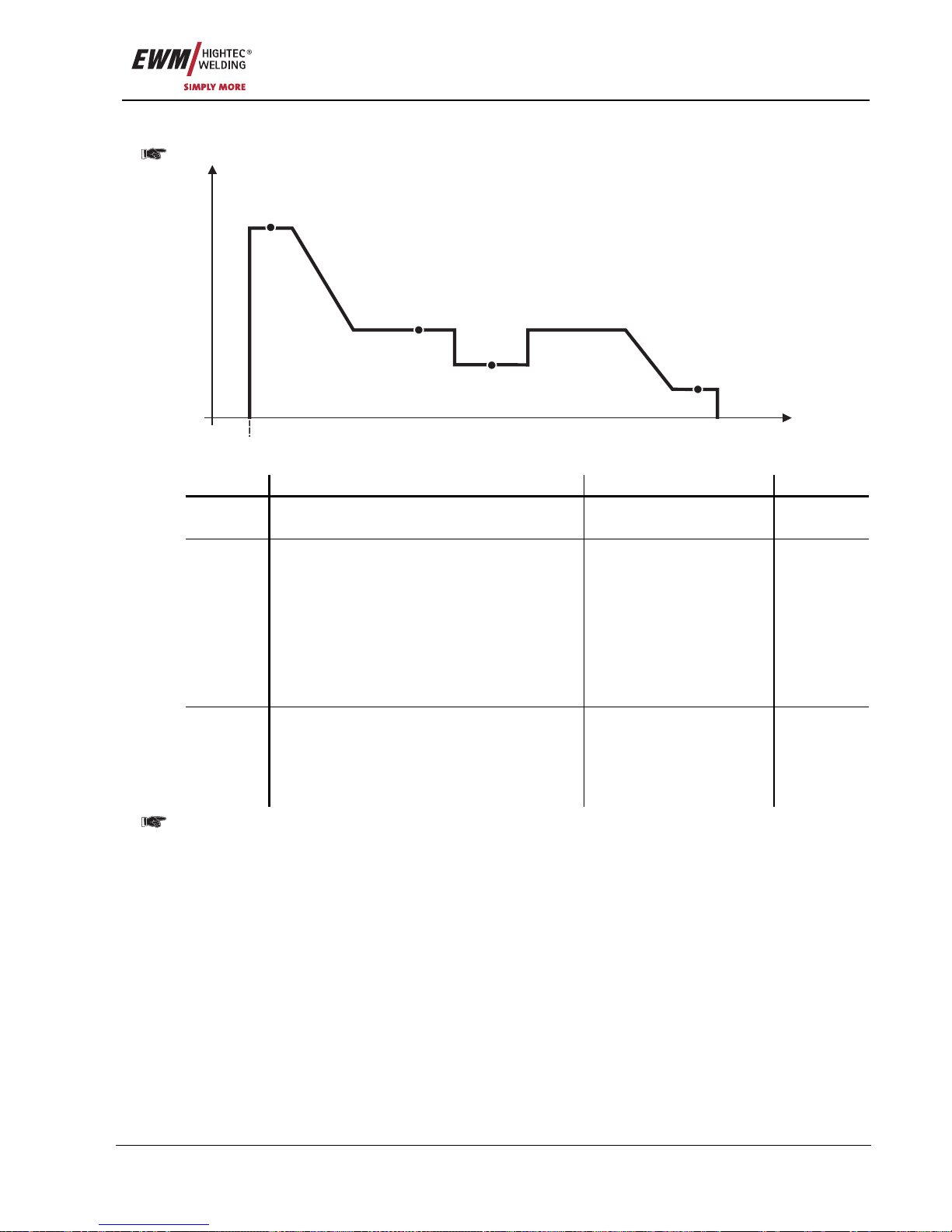
5.2.6.7 Welding process changeover
Pulse arc welding machines only.
t
I
P
A
P
B
P
END
P
START
Figure 5-22
Program Setting option Relates to Setting
P
START
Pulse arc welding process on/off
Changes using PC300.Net software
All special, non-latched
All special, latched
1 (= on)
0 (= off)
PA/PB
Welding process changeover
If P
A
contains a standard arc process, there is
a changeover to the pulse arc process, and
vice versa.
Changes using PC300.Net software
(EXPERT machine series: Can also be
changed using M3.1x, see chapter "MIG/MAG
parameter overview, M3.1x")
Non-latched/latched mode
with alternating welding
process
Non-latched/latched special
with alternating welding
process
Latched special with
welding process
changeover
1 (= active)
0 (= inactive)
P
END
Pulse arc welding process on/off
Changes using PC300.Net software
(Switched on for all forceArc JOBs in factory
settings)
All special, non-latched
All special, latched
1 (= on)
0 (= off)
The settings are saved with the JOB and apply to all programs for that JOB.
Page 46
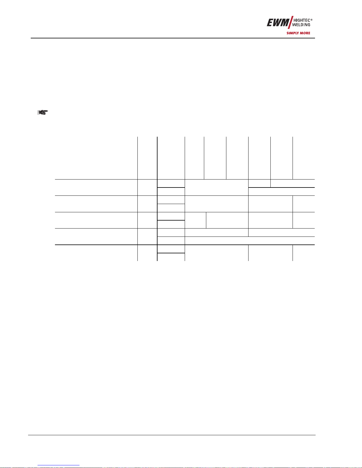
Functional characteristics
MIG/MAG welding
46 Item No.: 099-005073-EWM01
5.2.7 Main program A mode
Different welding tasks or positions on a workpiece demand various welding performances (operating
points) or welding programs. The following parameters are stored in each of the up to 16 programs:
• Operating mode
• Welding type
• Superpulses (ON/OFF)
• Wire feed speed (DV2)
• Voltage correction (U2)
• Dynamics (DYN2)
P
START
, PB, and P
END
are factory set as “relative programs”, i.e. they are dependent on a percentage
of the WF value of main program P
A
(switching between relative and absolute wire feed values,
see chapter “WF Speed Switching (absolute / relative)”.
The user can change the welding parameters for the main programs using the following components.
Program
changeover
Program
Operating
mode
Welding
process
Superpulse
Wire speed
Voltage
correction
Dynamics
P0 Yes
1)
Yes
2)
M3.71
Wire feed control
Yes
P1...15
Yes
Yes
P0 R20
Remote control
Yes
3)
P1...9
No Yes
1)
No
P0 R40
Remote control
Yes
3)
P1...15
No Yes Yes
2)
No
P0 Yes No PC 300.NET
Software
No
P1...15 Yes
P0 PowerControl 2
Welding torch
Yes
P1...15
No Yes No
1) Setting carried out using rotary dial
2) Internal memory
3) Powercontrol torch not connected
Page 47
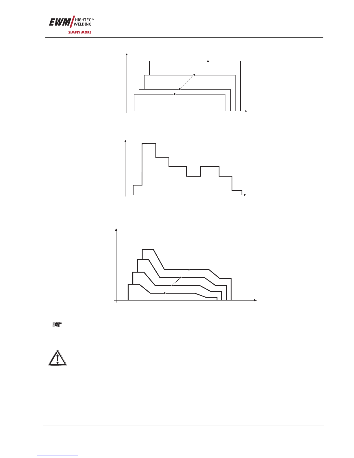
Functional characteristics
MIG/MAG welding
Item No.: 099-005073-EWM01 47
Example 1: Welding workpieces with different sheet metal thicknesses (non-latched )
t
I
P
A0
P
A1
P
A8
P
A9
Figure 5-23
Example 2: Welding different positions on a workpiece (latched)
t
I
P
A0
P
A1
P
A2
P
A4
P
A3
P
A3
P
A4
P
A5
Figure 5-24
Example 3: Aluminium welding of different sheet metal thicknesses (non-latched or latched
special)
P
A0
P
A1
P
A8
P
A9
t
I
Figure 5-25
This mode can be used to define 16 different programs (P
A0
to P
A15
) for one program sequence. The
wire speed, arc length correction and dynamics/choke effect can be set for each operating point.
The following applies to program P0: The wire speed, arc length correction and dynamics/choke
effect are set using the buttons on the M3.70 wire feed controller.
Changes to the welding parameters are saved immediately!
Page 48
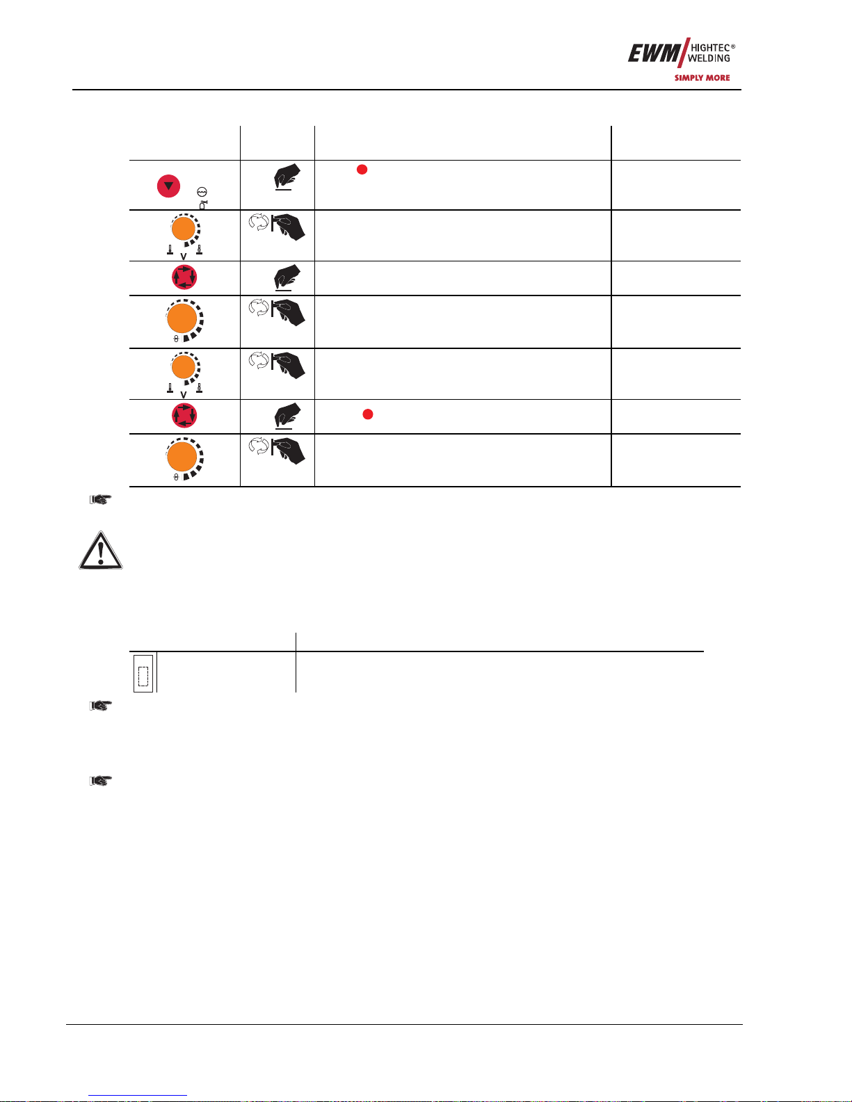
Functional characteristics
MIG/MAG welding
48 Item No.: 099-005073-EWM01
5.2.7.1 Selecting parameters (program A) using wire feed unit control M3.70
Operating
Element
Action Result Display
VOLT
PROG
x x
Press
PROG
(program number)
Select program number
x x
Select parameter LED “Main program (P
A
)”
m/min
Set wire speed
Set voltage correction
1 x
Select
DYN
Dynamics parameter
m/min
Set dynamics
Changes to the welding parameters can only be made when the key switch is in position "1".
5.2.8 MIG/MAG automatic cut-out
If pressing the torch trigger does not ignite the arc or if the arc is interrupted by the torch being
removed during the welding process, automatic cut-out occurs within 5 seconds. The welding
machine ends the welding process immediately (open circuit voltage or welding current, wire
feed and shielding gas are shut off).
5.2.9 Standard MIG/MAG torch
The MIG welding torch trigger is essentially used to start and stop the welding process.
Operating elements Functions
Torch trigger • Start/stop welding
It is also possible to change over between welding programs by tapping the torch trigger,
depending on the machine control configuration.
(see "Program changeover with standard torches (P8)" chapter)
5.2.10 MIG/MAG special-torches
Function specifications and more indepth information can be found in the operating manual for
the relevant welding torch!
The following special torches can be used together with this welding machine:
• Up/down welding torch with one rocker
− for setting the wire speed
• PowerControl welding torch with one rocker and single-digit digital display
− for calling up and displaying up to 10 welding programs, or
− for infinite, percentage-based operating point setting and display
• PowerControl 2 welding torch with four triggers and three-digit digital display
− for setting and displaying the welding performance and voltage correction, or
− for calling up programs and JOBs, as well as for displaying the corresponding parameters
• Push/pull welding torch with integrated wire feed unit
− for even wire feeding with extra long tube packages
− and potentiometer to control the wire-feed speed, where necessary
Page 49
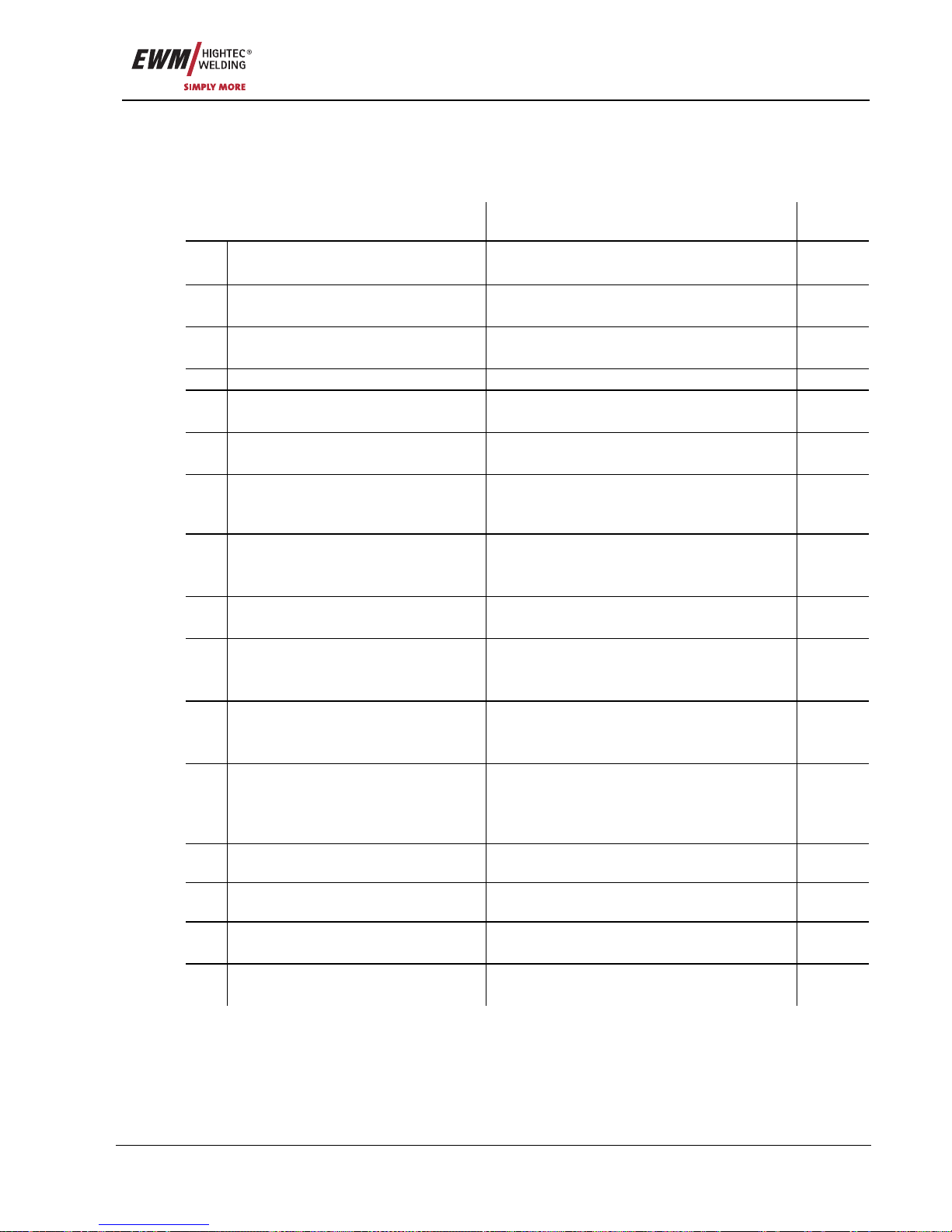
Functional characteristics
MIG/MAG welding
Item No.: 099-005073-EWM01 49
5.2.11 Special parameter, “M3.70/M3.71”
The special parameters cannot be viewed directly since they are normally only set and stored once. The
machine control offers the following special functions:
5.2.11.1 Special parameters list
Function Setting options Ex
works
P1 Ramp time for wire inching 0 = normal inching (10s ramp time)
1 = fast inching (3s ramp time)
1
P2 Block program "0" 0 = P0 enabled
1 = P0 blocked
0
P3 PowerControl torch display mode 0 = normal display
1 = alternating display
0
P4 Program limitation Programs 2 to max. 15 15
P5 Special cycle in the special latched
and non-latched operating modes
0 = normal (previous) non-latched/latched
1 = WF3 cycle for non-latched/latched
0
P61 Enable special jobs SP1 to SP3 0 = no enabling
1 = enabling of Sp1-3
0
P7 Correction operatio n, threshold value
setting
0 = correction operation switched off
1 = correction operation on
"Main program (PA)" flashing
0
P82 Program changeover with standard
torch
0 = no program changeover
1 = special latched
2 = specific latched special (n cycle active)
0
P9 Lat. and sp. lat. tapping start 0 = no latched tapping start
1 = latched tapping start possible
0
P102 One or two-wire feed operation 0 = single operation
1 = dual operation, this unit is the "master"
2 = dual operation, this unit is the "slave"
0
P11 Special latched tapping time 0 = tapping function switched off
1 = 300ms
2 = 600ms
1
P122 JOB list changeover 0 = task-oriented JOB list
1 = actual JOB list
2 = actual JOB list, JOB changeover activated
via accessories
0/14
P132 Lower limit
remote JOB changeover
Lowest JOB that can be selected using
PowerControl 2 torches.
129
P142 Upper limit
remote JOB changeover
Highest JOB that can be selected using
PowerControl 2 torches.
169
P15 Hold function 0 = hold values are not displayed
1 = hold values are displayed.
1
Key3 Software key switch 0 = system complete
1 = system not complete
1
1) PHOENIX EXPERT range only
2) PHOENIX EXPERT und PROGRESS ranges only
3) PHOENIX BASIC range only
4) See note in the relevant section of this chapter
Page 50
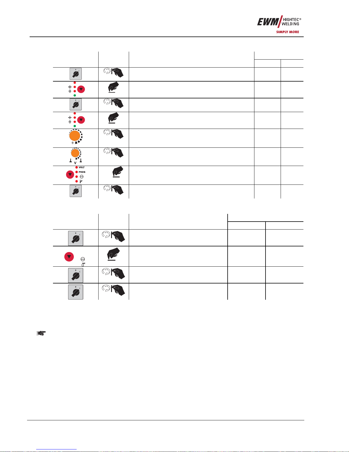
Functional characteristics
MIG/MAG welding
50 Item No.: 099-005073-EWM01
5.2.11.2 Selecting, changing and saving parameters
Display
Operating
element
Action Result
Left Right
Switch off the welding machine - -
HOLD
AMP
Keep the key button pressed - -
Switch on welding machine - -
HOLD
AMP
Release the key button P 1 Value
m/min
Parameter selection
(see list of special parameters)
P 1-x,
SCH
Value
Parameter setting
(see list of special parameters)
P x Value
1 x
Saving the special parameters PHO 371
Switch of the welding machine and restart in order
to put the modifications into effect
- -
5.2.11.3 Reset to factory settings
It is possible to reset all special parameters back to the factory settings.
Display
Operating
Element
Action Result
left right
Switch off the welding machine - -
VOLT
PROG
Press and hold button - -
Switch on the welding machine t1 on
Switch welding machine off and back
on again to activate the changes
- -
5.2.11.4 Ramp time for wire inching (P1)
The wire inching starts with a speed 1.0 m/min for 2 secs. It is subsequently increased to a ramp function
to 6.0 m/min. The ramp time can be set between two ranges.
5.2.11.5 Program "0", releasing the program block (P2)
In previous versions of the M3.70/M3.71 control system the block is dependent on the key switch
setting. With this version a block will only be effective when the locked status is active.
The program P0 (Potentiometer program) is blocked. The operation is possible only with P1...P15.
5.2.11.6 Display mode torch power control (P3)
The display of the torch power control shows program number or Up-Down setting in the normal
condition. It can be switched over to a blinking display. Then the program number and the welding type
(normal/pulse) are displayed alternately in the program operation. In Up-Down operation the Up-Down
settings and the Up-Down symbol are displayed alternately.
Page 51
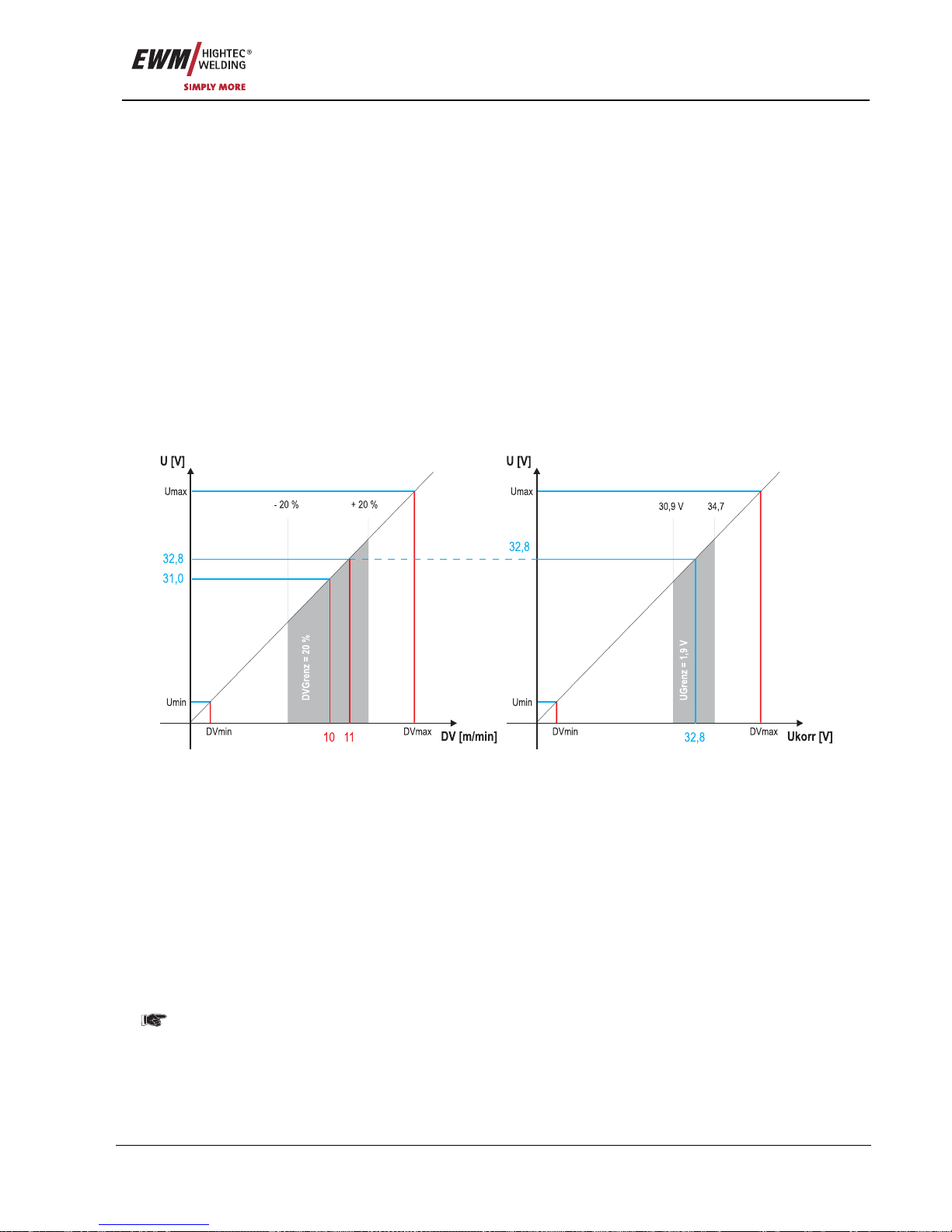
Functional characteristics
MIG/MAG welding
Item No.: 099-005073-EWM01 51
5.2.11.7 Program limit (P4)
The number of the absolute programs can be limited to above limit.
5.2.11.8 Special cycle in the operating modes special latched and non-latched (P5)
In the “normal” cycle of latched/non-latched the system starts with the start program Dvstart and
subsequently enters into the main program DV2.
In the “DV3 cycle” of latched/non-latched, the system starts with the start program Dvstart and
subsequently enters into the reduced main program DV3, remains there for the time T3 and then changes
automatically into the main program DV2. As a result an additional program is available in the cycle.
5.2.11.9 Enabling special JOBs SP1 to SP3 (P6)
This function is not available with machine control M3.71.
The JOB changeover is blocked if the key switch is in the “0” position.
This block can be cancelled for the special JOBs (SP1 - SP3).
5.2.11.10 Correction operation, threshold value setting (P7)
The correction operation is switched on and off for all JOBs and their programs at the same time. A
correction operation is specified for wire speed (DV) and welding voltage correction (Ukorr) for each JOB.
The correction value is saved separately for each program. The correction range can be maximum 30%
of the wire speed and +/-9.9 V welding voltage.
Figure 5-26
Example for the operating point in correction mode:
The wire speed in one program (1 to 15) is set on 10.0 m/min.
This corresponds to a welding voltage (U) of 31.0 V. When the key switch is set to "0" position, welding in
this program can only be carried out with these values.
To allow the welder also to perform wire and voltage correction in program mode, the correction mode
must be switched on and limit values for wire and voltage must be specified.
Setting of the correction limit value = WFlimit = 20% / Ulimit = 1.9 V
Now the wire speed can be corrected by 20% (8.0 up to 12.0 m/min) and the welding voltage by +/-1.9 V
(3.8 V).
In the example the wire speed is set on 11.0 m/min. This corresponds to a welding voltage of 32.8 V
Now the welding voltage can be corrected by further 1.9 V (30.9 V and 34.7 V).
The values for voltage and wire-speed correction will be reset if the key switch is moved to the "1"
setting.
Page 52
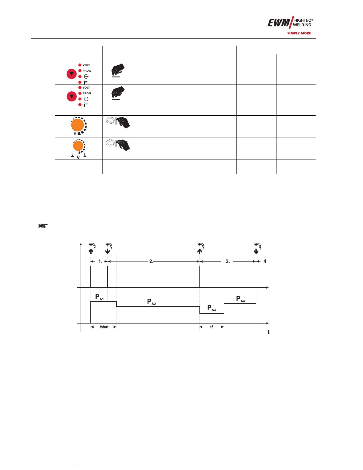
Functional characteristics
MIG/MAG welding
52 Item No.: 099-005073-EWM01
Display (example) Operating
Element
Action Result
Left Right
Press key button until only LED
„PROG“ is shining
7,5 (DV) 4 (prog.-no.)
4 sec.
Keep the key button pressed 0 (DVGrenz) 2.0 (UKorr)
Release the key button 0 (DVGrenz) 2.0 (UKorr)
m/min
Set tolerance value for wire speed 10 (DVGrenz) 2.0 (UKorr)
Set tolerance value for voltage
tolerance
10 (DVGrenz) 5.0 (UKorr)
Wait approx. 5 secs. Tolerance limits
(DV: 10%; U: +/- 5.0 V) were entered.
7.5 (DV) 4 (prog.-no.)
5.2.11.11 Program changeover with standard torch (P8)
Special latched
In "Latched absolute program sequence", the machine starts at the first cycle with absolute program 1.
In the second cycle, the machine switches to absolute program 2, once the start time "tstart" has elapsed.
In the 3rd cycle, the unit switches to absolute program 3. After "t3" is elapsed, the unit is automatically
switched to absolute program 4.
This function is only available if no other accessory components such as remote controls or
special torches are connected.
Programs cannot be switched over on the wire feed unit control either.
Figure 5-27
Page 53
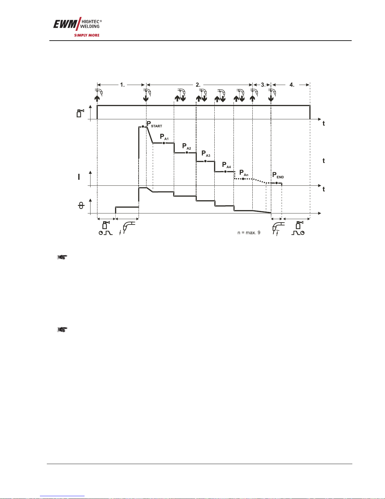
Functional characteristics
MIG/MAG welding
Item No.: 099-005073-EWM01 53
Specific latched special (n cycle)
In the n cycle program sequence, the unit starts in the 1st cycle with start program P
start
from P
1
In the second cycle, the machine switches to absolute program 2, once the start time "tstart" has elapsed.
Tapping switches to other programs (P
A1
to max. PA9).
Figure 5-28
The number of programs (P
An
) corresponds to the cycle number specified under N cycle.
1st cycle
• Press and hold torch trigger.
• Shielding gas is expelled (gas pre-flows).
• Wire feed motor runs at "creep speed".
• Arc ignites after the wire electrode makes contact with the workpiece, welding current is flowing (start
program P
START
from PA1)
2nd cycle
• Release torch trigger.
• Slope to main program P
A1
.
The slope to main program P
A1
is given at the earliest after the set time t
START
elapses and at the
latest when the torch trigger is released. Tapping (pressing briefly and releasing within 0.3 sec)
can switch to other programs. Programs P
A1
to P
A9
are possible.
3rd cycle
• Press and hold torch trigger.
• Slope to end program P
END
from PAN. The program can be stopped at any time by pressing the torch
trigger longer than 0.3 sec. P
END
from PAN is then executed.
4th cycle
• Release torch trigger.
• WF motor stops.
• Arc is extinguished after the pre-selected wire burn-back time elapses.
• Gas post-flow time elapses.
Page 54
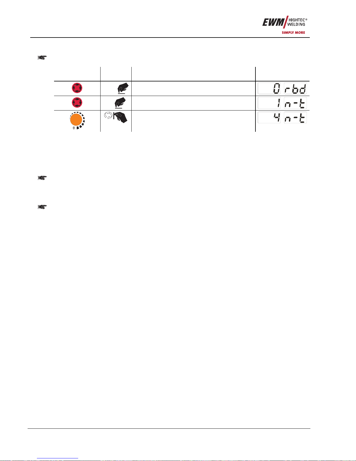
Functional characteristics
MIG/MAG welding
54 Item No.: 099-005073-EWM01
5.2.11.12 N cycle setting
The n cycle function should always be activated before the n cycle setting (see "Program
changeover with standard torch (P8)".
Operating
element
Action Result Display
3 sec
Select wire burn-back
1 x
Select N cycle setting
m/min
Parameter setting (setting range 1 to 9)
5.2.11.13 Latched/special-latched tap start (P9)
In latched – tap start – operating mode it is possible to switch straight to the second step by tapping the
torch trigger; it is not necessary for current to be flowing.
The welding can be halted by pressing the torch trigger for a second time.
5.2.11.14 "Single or dual operation" (P10) setting
If the system is fitted with two wire feeds, no further accessory components may be operated on
the 7-pole connection socket (digital)!
This relates to digital remote controls, robot interfaces, documentation interfaces, welding torches with
digital control lead connection, etc.
No second wire feed may be connected in single operation (P10 = 0)!
• Remove connections to the second wire feed
In dual operation (P10 = 1 or 2), both wire feed units must be connected and configured differently
on the controls for this operating mode!
• Configure one wire feed unit as the master (P10 = 1)
• Configure the other wire feed unit as a slave (P10 = 2)
Wire feed units with key switches (optional, see Key switches chapter) must be configured as
masters (P10 = 1).
The wire feed configured as the master is active after the welding machine is switched on. There are no
other functional differences between the wire feeds.
5.2.11.15 Latched special tapping time setting (P11)
The tapping time for changing over between the main program and reduced main program can be set in
three levels.
0 = no tapping
1 = 300ms (factory setting)
2 = 600ms
Page 55

Functional characteristics
MIG/MAG welding
Item No.: 099-005073-EWM01 55
5.2.11.16 JOB list switching (P12)
Factory setting for parameter P12
• PHOENIX 301,351,421 PROGRESS KG 0
• PHOENIX 333 PROGRESS KG 1
• PHOENIX 303 PROGRESS coldArc KG 1
• PHOENIX PROGRESS 4.4L 0
• PHOENIX PROGRESS DRIVE 4L coldArc 1
Value Designation Explanation
0 Task-oriented
JOB list
The JOB numbers are sorted by welding wires and shielding gases.
JOB numbers may be skipped during selection where rele vant.
1 Actual JOB list JOB numbers correspond to the actual memory cells. Each JOB can be
selected; no memory cells are skipped during selection.
2 Actual JOB list,
JOB changeover active
As for the actual JOB list. JOB changeover is also possible with
accessory components, such as the PowerControl 2 torch.
When switching between the actual and task-oriented JOB lists, the assignment of the welding
tasks to the JOB numbers will change!
• The "JOB list" sticker is no longer valid!
In the appendix you will find pictures of both JOB lists. See "JOB list sticker" chapter.
All JOB number specifications in these instructions relate to the factory settings.
5.2.11.17 Creating user-defined JOB lists
A consecutive memory range where accessories such as the PowerControl 2 torch can be used to
switch between JOBs will be created.
• Set special parameter P12 to "2".
• Set "Program or Up/Down function" changeover switch to "Up/Down" position.
• Select an existing JOB which is closest to the required result.
• Copy JOB to one or more target JOB numbers.
If any JOB parameters need to be changed, select the target JOBs in sequence and change the
parameters individually.
• Set special parameter P13 to the lower limit and
• Set special parameter P14 to the upper limit of the target JOBs.
• Set "Program or Up/Down function" changeover switch to "Program" position.
JOBs can be changed over in the specified range using the accessory compone nt.
Page 56
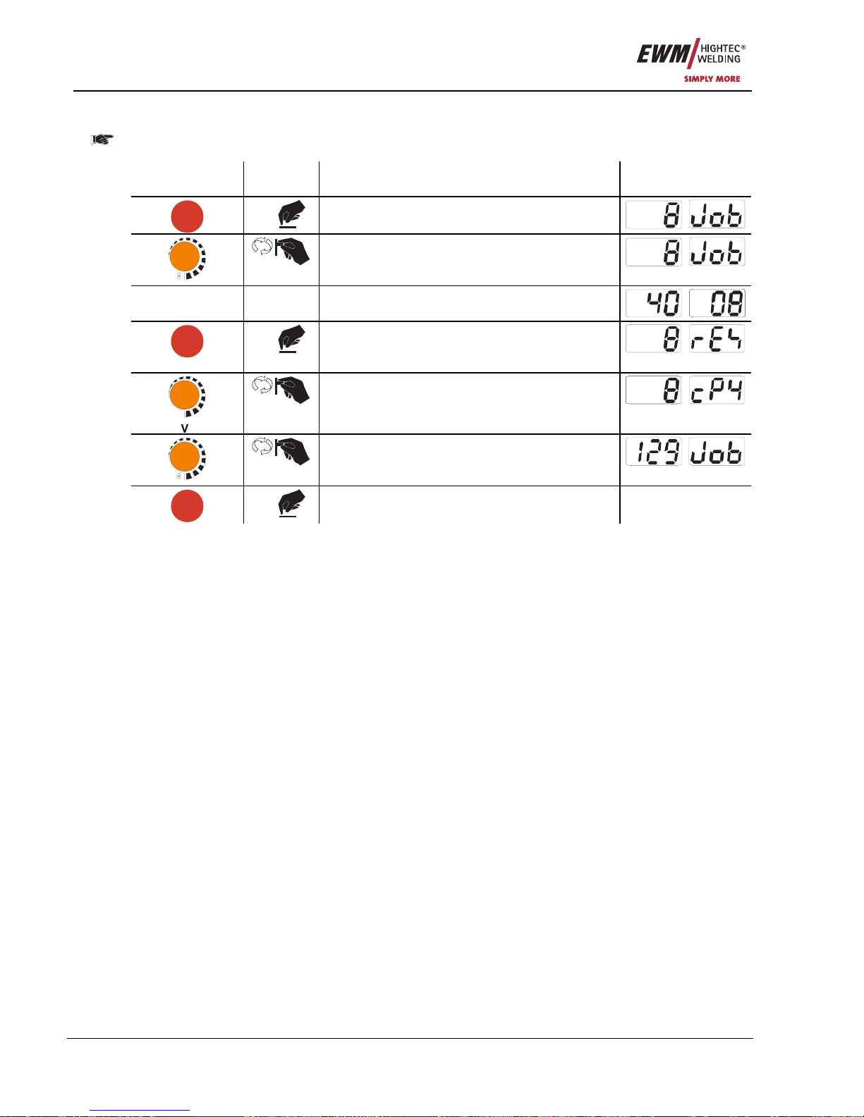
Functional characteristics
MIG/MAG welding
56 Item No.: 099-005073-EWM01
5.2.11.18 Copying JOBs, "Copy to" function
The possible target range is between 129 - 169.
• First configure special parameter P12 to P12 = 2 or P12 = 1!
Operating
element
Action Result Display
JOBLIST
1 x
Select JOB list
m/min
Select the source JOB
- -
Wait for around 3 seconds until the JOB has
been transferred
JOBLIST
1 x
> 5s
Keep button pressed for around 5s
Setting to copy function ("Copy to")
m/min
Select JOB number of the target JOB
JOBLIST
1 x
Save
The JOB is copied to the new position
By repeating the last two steps, the same source JOB can be copied to multiple target JOBs.
If the control does not register any user activity for longer than 5 seconds, the parameter display is shown
once more and the copy process is complete.
5.2.11.19 Lower and upper limits of the remote JOB changeover process (P13,P14)
The highest and lowest JOB numbers which can be selected using accessory components, such as the
PowerControl 2 torch.
Avoids an accidental changeover into undesirable or undefined JOBs.
5.2.11.20 Hold function (P15)
Hold function active (P15 = 1)
• Mean values for the last main program parameters used for welding are displayed.
Hold function not active (P15 = 0)
• Setpoint values for the main program parameters are displayed.
5.2.11.21 Software key switch (SCH)
The key switch function allows the welding machine to be locked using the software. This is useful on
units that do not have a key switch (e.g. PHOENIX 401 BASIC).
Page 57
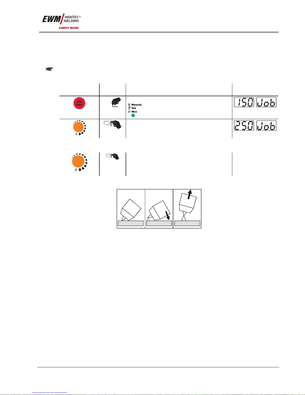
Functional characteristics
TIG welding
Item No.: 099-005073-EWM01 57
5.3 TIG welding
5.3.1 TIG welding task selection
• Select JOB 250 (TIG welding task).
It is only possible to change the JOB number when no welding current is flowing.
On decompact welding systems, the "JOB list" sticker is located on the inside on the wire feed unit cover;
with compact machines it is on the right-hand power source cover.
Operating
element
Action Result Display
1 x
Select JOB number input
comes on
m/min
Set the JOB number
The machine adopts the required setting after
approx. 3 seconds
5.3.2 TIG welding current setting
The welding current is normally set using the “Wire speed” rotary dial.
m/min
Welding current is set The welding current
and voltage change
depending on the
setting
5.3.3 TIG arc ignition
5.3.3.1 Liftarc
a) b) c)
Figure 5-29
The arc is ignited on contact with the workpiece:
a) Carefully place the torch gas nozzle and tungsten electrode tip onto the workpiece and press the torch
trigger (liftarc current flowing, regardless of the main current set).
b) Incline the torch over the torch gas nozzle to produce a gap of approx. 2-3 mm between the electrode
tip and the workpiece. The arc ignites and the welding current is increased, dependin g on the
operating mode set, to the ignition or main current set.
c) Lift off the torch and swivel to the normal position.
Ending the welding process: Release or press the torch trigger depending on the operating mode
selected.
Page 58
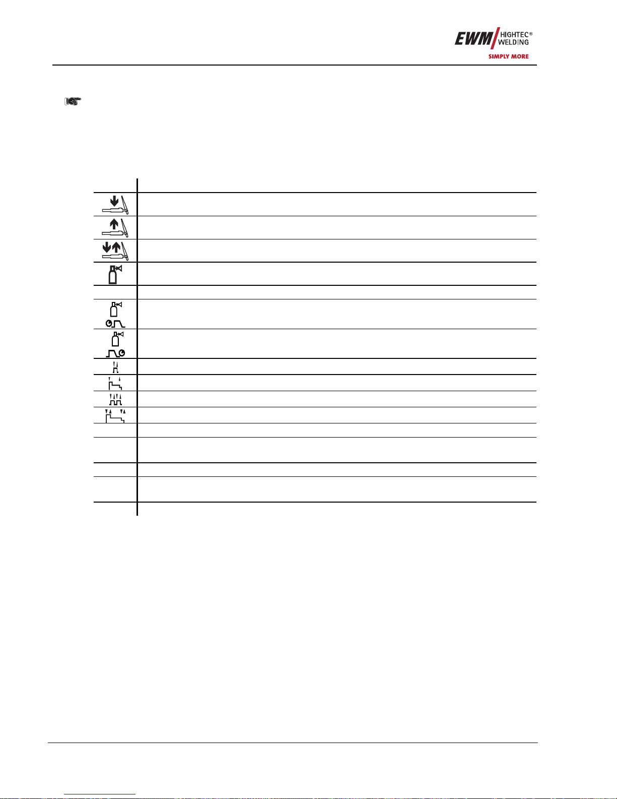
Functional characteristics
TIG welding
58 Item No.: 099-005073-EWM01
5.3.4 TIG function sequences / operating modes
The arc ignition takes place with Liftarc (see chapter "TIG Arc ignition"). After unsuccessful
ignition or interruption of the welding procedure, the automatic cut-out takes place (see chapter
"TIG Automatic cut-out").
The welding parameters are optimally preset for a multiplicity of applications (can be adapted if
required (see chapter TIG Program sequence "Program-Steps mode"). In every operation mode
the Superpulse function can be used.
5.3.4.1 Explanation of signs and functions
Symbol Meaning
Press torch trigger
Release torch trigger
Tap torch trigger (press briefly and release)
Shielding gas flowing
I Welding output
Gas pre-flows
Gas post-flows
Non-latched
Special, non-latched
Latched
Special, latched
t Time
PSTART Ignition program
Flat Main program
Hor.
vert.
Reduced main program
PEND End program
Page 59
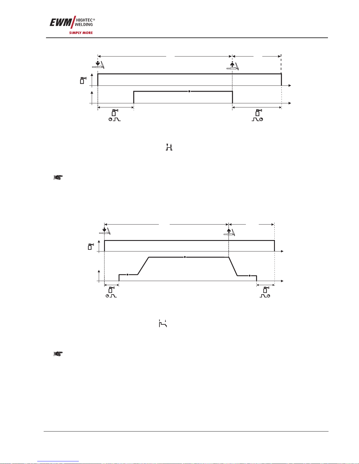
Functional characteristics
TIG welding
Item No.: 099-005073-EWM01 59
5.3.4.2 Non-latched mode
I
t
t
1. 2.
P
A
Figure 5-30
Selection
• Select non-latched operating mode
.
Step 1
• Press and hold torch trigger.
• Shielding gas is expelled (gas pre-flows).
The arc is ignited using liftarc.
• Welding current flows with pre-selected setting.
Step 2
• Release torch trigger.
• Arc is extinguished.
• Gas post-flow time elapses.
5.3.4.3 Special, non-latched
t
t
I
1. 2.
P
A
P
END
P
START
Figure 5-31
Selection
• Select non-latched special mode
.
Step 1
• Press and hold torch trigger
• Shielding gas is expelled (gas pre-flows)
The arc is ignited using liftarc.
• Welding gas flows with pre-selected setting in start program “P
START
”.
• After the “tstart” ignition current time elapses, the welding current rises with the set upslope time “tS1”
to the main program “P
A
”.
Step 2
• Release torch trigger.
• The welding current reduces with the downslope time “tSe” to the end program “P
END
”.
• After the end current time “end” elapses, the arc will extinguish.
• Gas post-flow time elapses.
Page 60
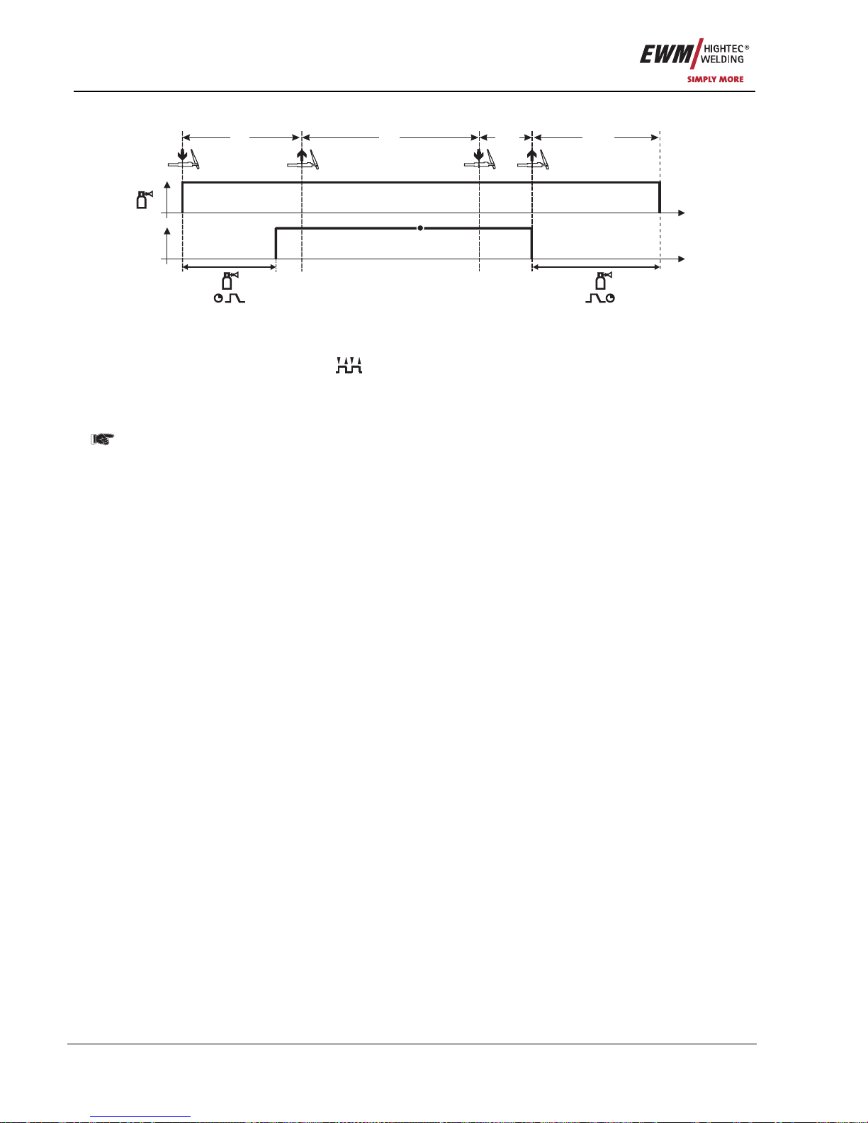
Functional characteristics
TIG welding
60 Item No.: 099-005073-EWM01
5.3.4.4 Latched mode
t
t
I
1. 2. 3. 4.
P
A
Figure 5-32
Selection
• Select latched operating mode
.
Step 1
• Press and hold torch trigger
• Shielding gas is expelled (gas pre-flows)
The arc is ignited using liftarc.
• Welding current flows with pre-selected setting.
Step 2
• Release torch trigger (no effect)
Step 3
• Press torch trigger (no effect)
Step 4
• Release torch trigger
• Arc is extinguished.
• Gas post-flow time elapses.
Page 61
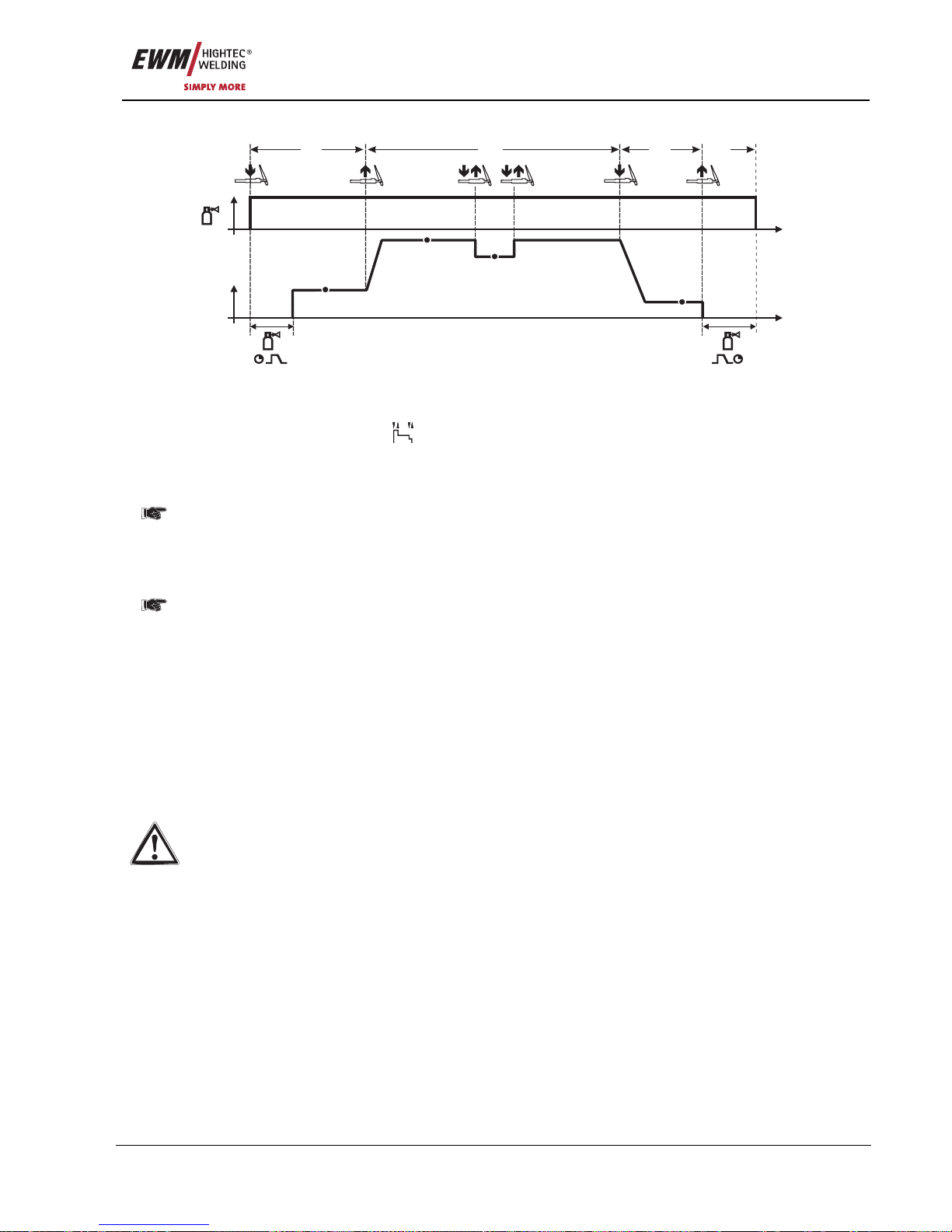
Functional characteristics
TIG welding
Item No.: 099-005073-EWM01 61
5.3.4.5 Latched special
t
t
I
1. 2. 3. 4.
P
A
P
B
P
END
P
START
Figure 5-33
Selection
• Select latched special mode
.
Step 1
• Press and hold torch trigger.
• Shielding gas is expelled (gas pre-flows).
The arc is ignited using liftarc.
• Welding gas flows at pre-selected setting in start program "P
START
".
Step 2
• Release torch trigger.
• Slope on main program "P
A
".
The slope on main program P
A
is given at the earliest after the set time t
START
elapses and at the
latest when the torch trigger is released.
Tapping can be used to switch to the reduced main program "P
B
". Repeated tapping will switch
back to the main program "P
A
".
Step 3
• Press the torch trigger.
• Slope to end program "P
END
".
Step 4
• Release torch trigger.
• Arc is extinguished.
• Gas post-flow time elapses.
5.3.5 TIG automatic cut-out
If the arc does not ignite after starting or if the arc is interrupted when the torch is moved away,
an automatic cut-out occurs after 5 sec. The gas and open circuit voltage (power uni t) are
switched off.
Page 62
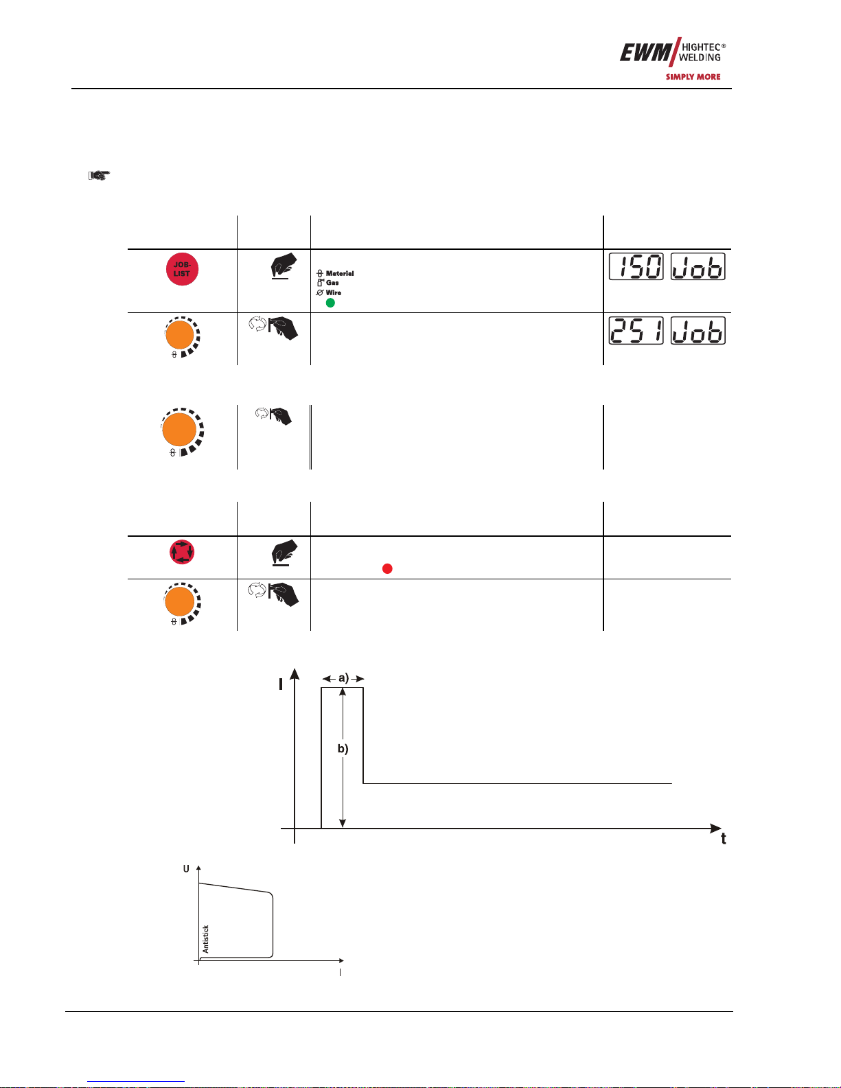
Functional characteristics
MMA welding
62 Item No.: 099-005073-EWM01
5.4 MMA welding
5.4.1 MMA welding task selection
• Select JOB 251 (MMA welding task).
It is only possible to change the JOB number when no welding current is flowing.
On decompact welding systems, the "JOB list" sticker is located on the inside on the wire feed unit cover;
with compact machines it is on the right-hand power source cover.
Operating
element
Action Result Display
1 x
Select JOB number input
comes on
m/min
Set the JOB number
The machine adopts the required setting after
approx. 3 seconds
5.4.2 MMA welding current setting
The welding current is normally set using the “Wire speed” rotary dial.
m/min
Welding current is set The welding current
and voltage change
depending on the
setting
5.4.3 Arcforcing
Operating
element
Action Result Display
X x
Select arcforcing welding parameter
Press until
DYN
“Dynamic” LED comes on.
-40 to +40
m/min
Arcforcing setting on the "Wire speed/welding
parameters" rotary dial
-40 to +40
5.4.4 Hotstart
The hotstart device improves the ignition of the stick electrodes using an increased ignition current.
a) = Hotstart time
b) = Hotstart current
I = Welding current
t = Time
5.4.5 Antistick
Anti-stick prevents the electrode from annealing.
If the electrode sticks in spite of the Arcforce device, the
machine automatically switches over to the minimum
current within about 1 second to prevent the electrode
from overheating. Check the welding current setting
and correct according to the welding task!
Page 63
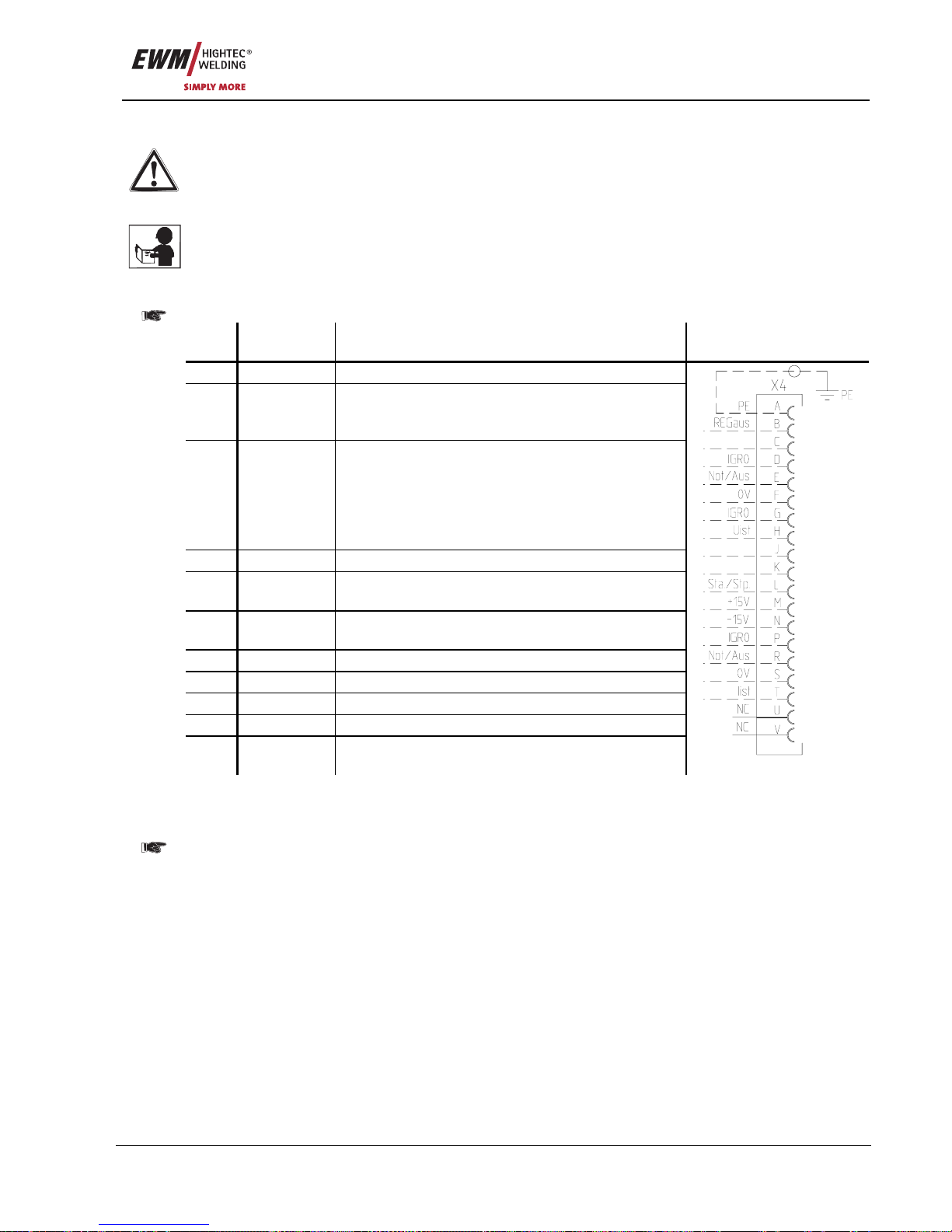
Functional characteristics
Interfaces
Item No.: 099-005073-EWM01 63
5.5 Interfaces
Only the accessory components described in these operating instructions may be connected.
Only plug accessory components into the relevant connection socket on the welding machine
and lock it when the machine is switched off. The component is detected automatically when the
welding machine is switched on.
Comprehensive descriptions can be found in the operating instructions for the relevant
accessory components.
5.5.1 Automation interface
These accessory components can be retrofitted as an option, see Accessories chapter.
Pin Input /
output
Description Diagram
A
Output PE Connection for cable shielding
D
Output
(open
collector)
IGRO Current flows signal I>0 (maximum load 20
mA / 15 V)
0 V = welding current flows
E
+
R
Input Not/Aus Emergency stop for higher level shut-down
of the power source.
To use this function, jumper 1 must be
unplugged on PCB M320/1 in the welding
machine. Contact open = welding current
off
F
Output 0 V Reference po t ential
G/P
Output I>0 Power relay contact, galvanically isolated
(max. +/-15 V / 100 mA)
H
Output Uist Welding voltage, measured against pin F,
0-10 V (0 V = 0 V; 10 V = 100 V)
L
Input Str/Stp Start = 15 V / Stop = 0 V
1)
M
Output +15 V Voltage supply (max. 75 mA)
N
Output -15 V Voltage supply (max. 25 mA)
S
Output 0 V Reference po t ential
T
Output Iist Welding current, measured on pin F;
0-10 V (0 V = 0 A, 10 V = 1000 A)
1) The operating mode is given by the wire feed unit (the start / stop function equates to pressing the
torch trigger and is used in mechanised applications, for example).
The appendix includes a list of equivalent JOB numbers in the PC 300 software for the PHOENIX
BASIC and PHOENIX PROGRESS models.
With PHOENIX EXPERT models, the software JOB numbers are the same as those for the machine.
Page 64

Functional characteristics
Interfaces
64 Item No.: 099-005073-EWM01
5.5.2 RINT X11 robot interface
The standard digital interface for automated applications
(optional, retrofitting on the machine or external fitting by the customer)
Functions and signals:
• Digital inputs: Start/stop, operating mode, job and program selection, inching, gas test
• Analogue inputs: Control voltages for welding output, correction, dynamics
• Relay outputs: Current flows, welding data monitoring, ready for welding, etc.
5.5.3 BUSINT X10 Industrial bus interface
The solution for easy integration into automated production lines, with for example
• Profi bus
• CAN bus and
• Interbus systems
(optional, external installation by customer)
5.5.4 DVINT X11 Wire feed interface
For the flexible connection of special wire feed units (optional, retrofitting on the machine or externally by
the customer).
As examples: Binzel (APD system), Dinse wire feed systems.
5.5.5 PC Interfaces
PC 300 welding parameter software
Create all welding parameters quickly on the PC and easily transfer them to one or more welding
machines (accessories: set consisting of software, interface, connection leads).
Q-DOC 9000 welding data documentation software
(Accessories: set consisting of software, interface, connection leads)
The ideal tool for welding data documentation of, for example:
welding voltage and current, wire speed and motor current.
WELDQAS welding data monitoring and documentation system
Network-compatible welding data monitoring and documentation system for digital PHOENIX and
TETRIX machines
5.5.6 Setting options, internal
5.5.6.1 Switching between Push/Pull and intermediate drive
The plugs are located directly on PCB M3.70 in the wire feed unit.
Plug Function
on X24 Operation with Push/Pull welding torch (factory setting)
on X23 Operation with intermediate drive
Page 65
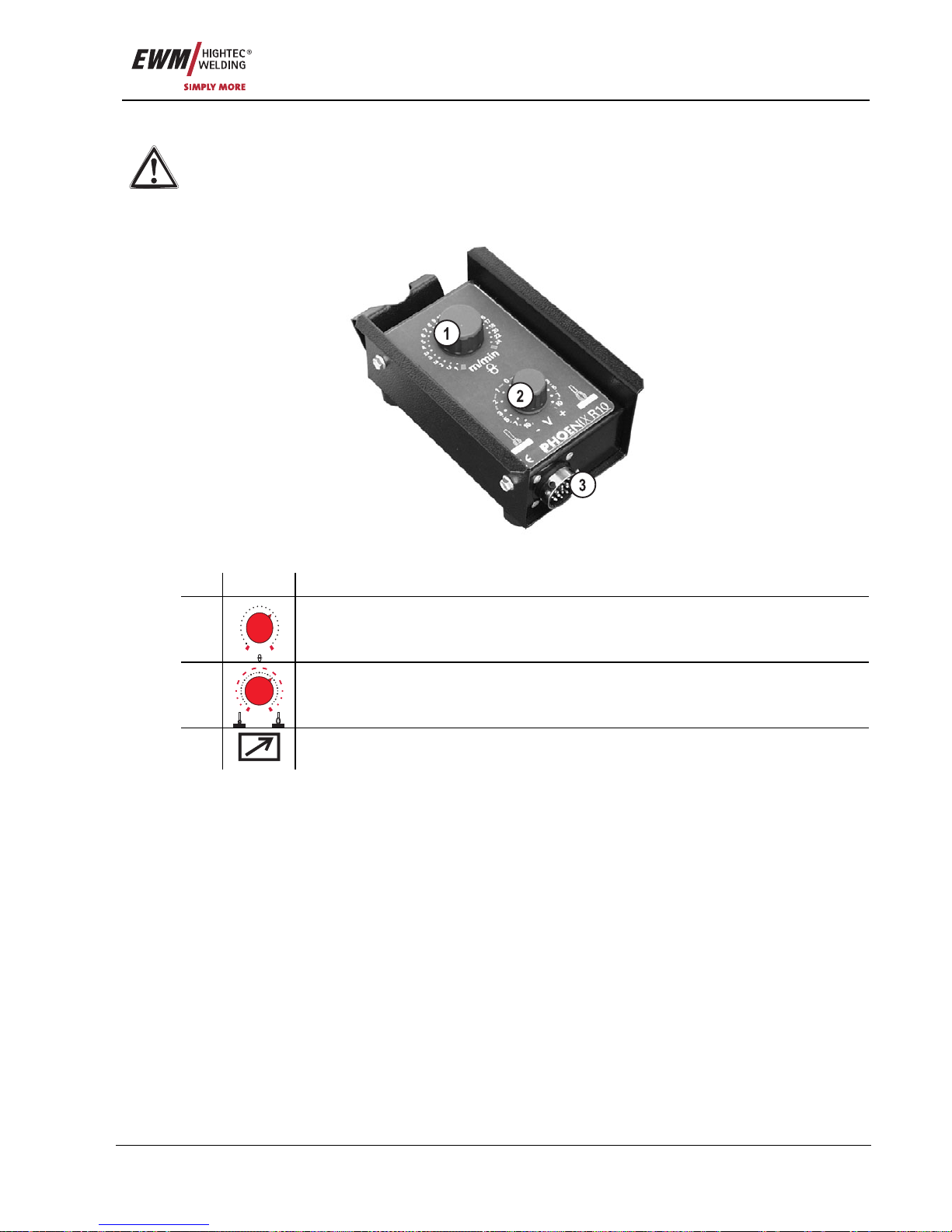
Functional characteristics
Remote control
Item No.: 099-005073-EWM01 65
5.6 Remote control
Only the remote controls described in these operating instructions may be connected. Plug the
remote control unit into the remote control connection socket on the welding machine or wire
feed unit and lock it only when the machine is switched off.
The remote control is detected automatically when the welding machine is switched on.
5.6.1 R10 manual remote control
Figure 5-34
Item Symbol Description 0
1
0,5
1
1,5
2
2,5
3
3,5
4
5
6
7
8
9
10
11
12
13
14
15
16
18
20
m/min
“Wire speed” rotary dial
Infinitely adjustable setting of the wire speed from min. to max.
(welding output, one-dial operation)
2
0
1
1
22
33
77
55
10
10
- V +
“Arc length correction” rotary dial
Arc length correction from -10 V to + 10 V
3
19-pole connection socket (analogue)
For connecting the control lead.
Page 66
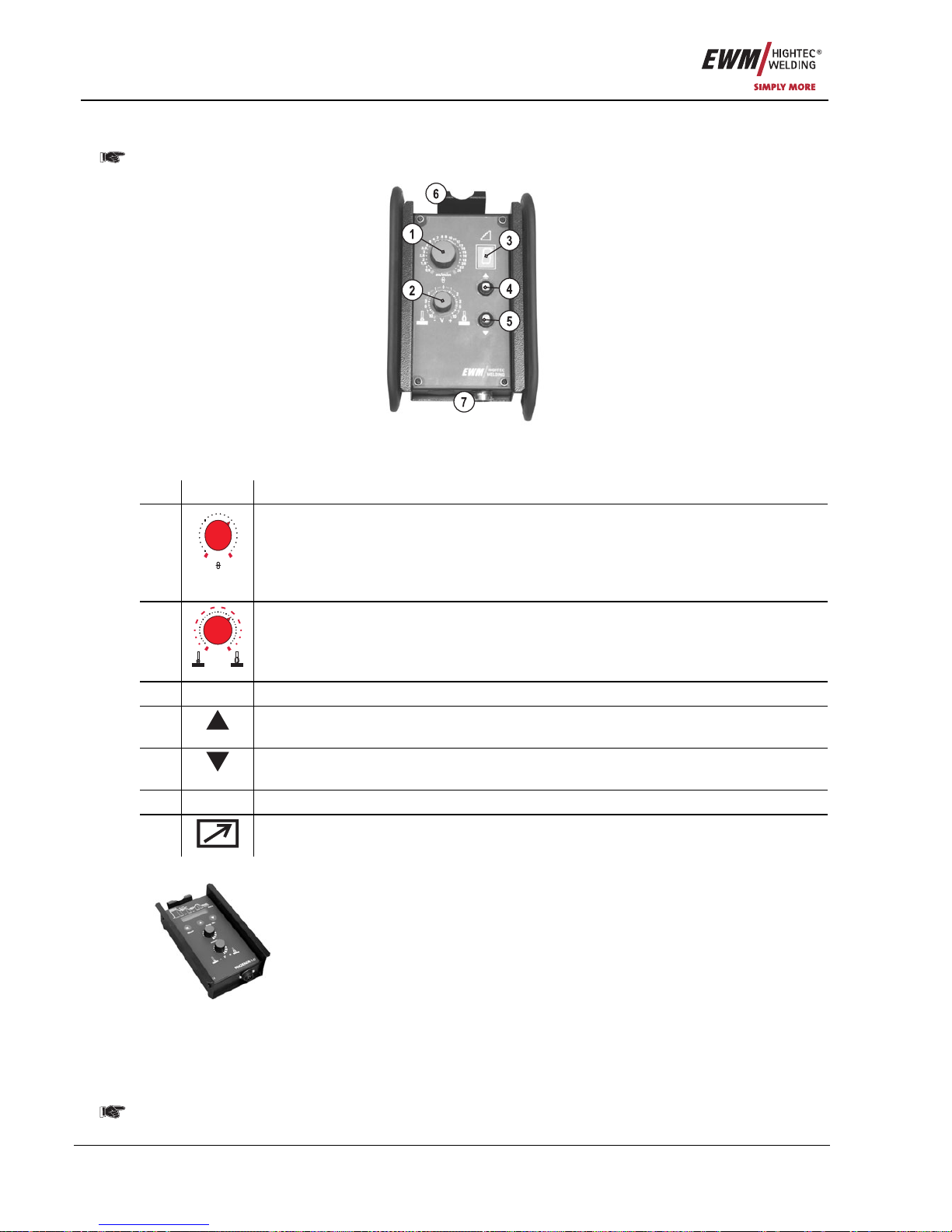
Functional characteristics
Remote control
66 Item No.: 099-005073-EWM01
5.6.2 Manual remote control R20
Manual remote controls R20 can only be used together with controls M3.70 or M3.71!
Figure 5-35
Item Symbol Description 0
1
0,5
1
1,5
2
2,5
3
3,5
4
5
6
7
8
9
10
11
12
13
14
15
16
18
20
m/min
"Wire speed" rotary dial
• Infinitely adjustable setting of the wire speed from min. to max.
(welding output, one-dial operation).
• The wire correction value is set in the correction operation with welding programs
(key switch set to "0").
2
0
1
1
22
33
77
55
10
10
- V +
"Arc length correction" rotary dial
• Arc length correction from -10V to +10V
• The arc correction value is set in the correction operation with welding programs
(key switch set to "0").
3 Display for showing the current program number
4
Program switching "Up" button
Select program number up
5
Program switching "Down" button
Select program number down
6 Holder for suspending the remote control
7
19-pole connection socket (analogue)
For connecting the control lead.
5.6.3 R40 manual remote control
Functions
• Create and retrieve up to 16 operating points/main programs
• Set program sequence
• Superpulse function "ON/OFF"
• MIG standard/MIG pulse arc welding switching
(EXPERT PULSE only)
• Preset number of main programs (PA1 to PA16)
• LCD display (16-digit ) for displaying the welding parameters
• LED for displaying the Hold function
• The remote control is connected to the digital remote control connection socket
on the welding machine (7-pole) via an extension cable
Detailed information can be found in the relevant operating instructions.
Page 67
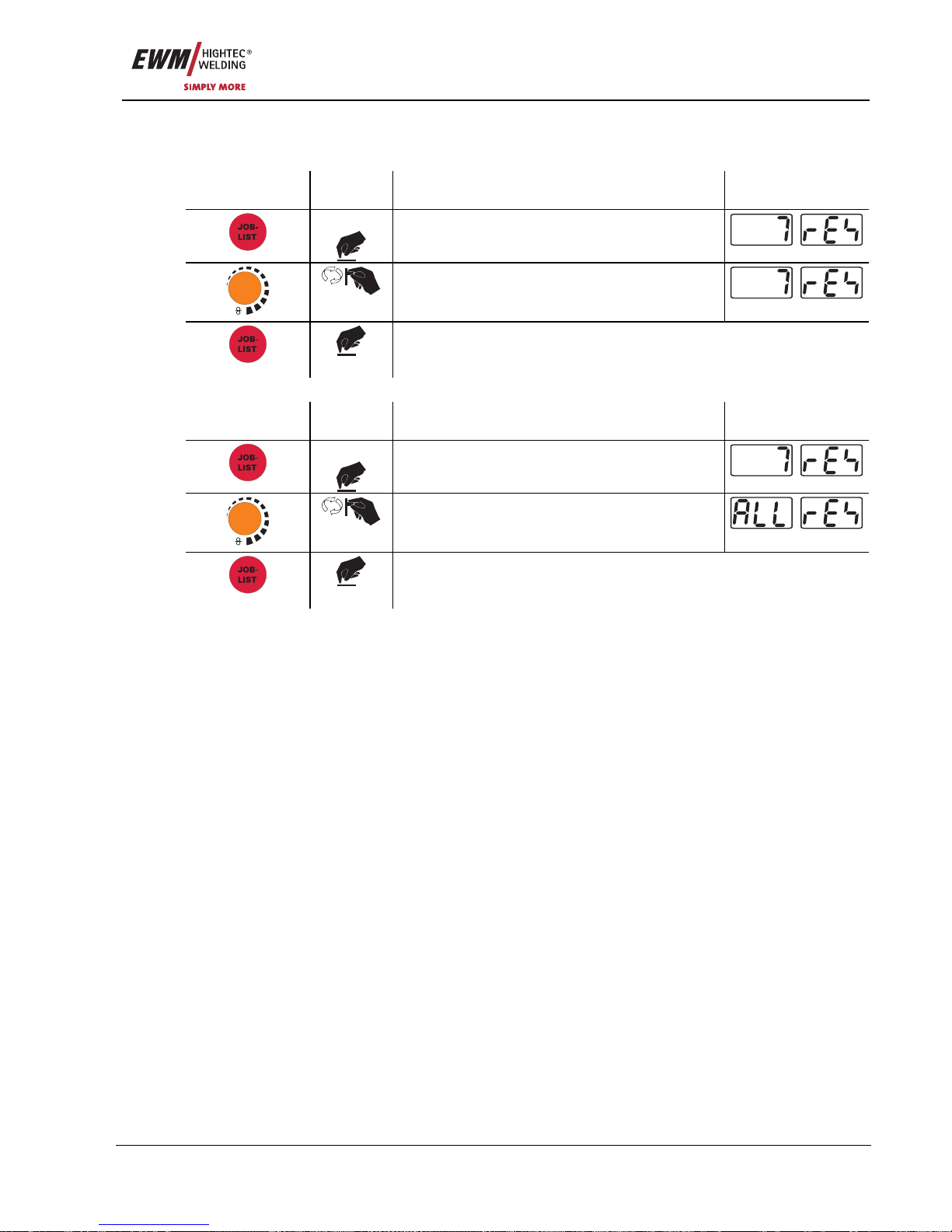
Functional characteristics
Resetting JOBs (welding tasks) to the factory settings
Item No.: 099-005073-EWM01 67
5.7 Resetting JOBs (welding tasks) to the factory settings
5.7.1 Resetting a single JOB
Operating
element
Action Result Display
3 sec.
Select JOB Reset
m/min
Set the JOB number to be reset
Confirm JOB reset.
(If not pressed within approx. 3 seconds, the machine switches to the
last parameters displayed and the JOB reset process is cancelled)
5.7.2 Resetting all JOBs
Operating
element
Action Result Display
3 sec.
Select JOB Reset
m/min
Set "All Reset" (after JOB 251)
Confirm JOB reset.
(If not pressed within approx. 3 seconds, the machine switches to the
last parameters displayed and the JOB reset process is cancelled)
Page 68
Commissioning
General
68 Item No.: 099-005073-EWM01
6 Commissioning
6.1 General
Warning – Risk from electrical current!
Follow the safety instructions on the opening pages entitled “For your safety”.
Connection and welding leads (e.g. electrode holder, welding torch, workpiece lead, interfaces)
may only be connected when the machine is switched off.
6.2 Area of application – proper usage
These welding machines are suitable exclusively for MIG/MAG, TIG and MMA welding.
Any other use is regarded as "improper" and no liability is assumed for any damage arising therefrom.
We can only guarantee smooth and trouble-free operation of the machines when used in
conjunction with the welding torches and accessories from our range.
6.3 Installation
Ensure that the machine is set up in a stable position and is appropriately secured.
With modular systems (power source, transport vehicle, cooling module), observe the operating
instructions for the relevant machine.
Set up the machine so that there is sufficient room to adjust the operating elements.
When lifting the wire feed unit, the wire spool should be removed (please see the operating
instructions for the transport vehicle for more information on crane work).
6.4 Mains connection
The operating voltage shown on the rating plate must match the mains voltage.
For mains fuse protection, please refer to the “Technical Data” chapter.
The correct mains plug must be attached to the mains supply lead on the machine.
The connection must be made by a qualified electrician in compliance with the relevant local laws
and regulations.
The phase sequence for three-phase machines is optional and has no effect on the fans direction
of rotation.
• Insert mains plug of the switched-off machine into the appropriate socket.
6.5 Machine cooling
To obtain an optimal duty cycle from the power components, the following precautions should be
observed:
• Ensure that the working area is adequately ventilated,
• Do not obstruct the air inlets and outlets of the machine,
• Do not allow metal parts, dust or other objects to get into the machine.
Page 69
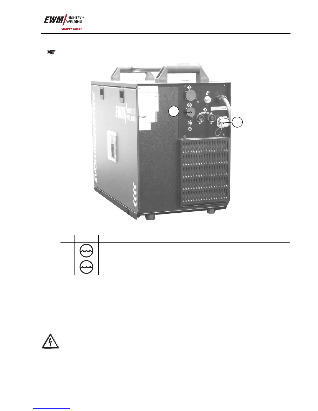
Commissioning
Workpiece lead, general
Item No.: 099-005073-EWM01 69
6.5.1 Cooling module connection
Observe the fitting and connection instructions given in the relevant operating instructions for the
cooling unit.
2
1
Figure 6-1
Item Symbol Description 0
1
8-pole connection socket
Cooling unit control lead
2
4-pole connection socket
Cooling unit voltage supply
• Engage the plug-in nipple with the blue marking on the coolant hose from the intermediate tube
package with the rapid-action closure coupling marked in blue on t he cooling unit.
• Engage the plug-in nipple with the red marking on the coolant hose from the intermediate tube
package with the rapid-action closure coupling marked in red on the cooling unit.
• Insert and lock the 8-pole control lead plug on the cooling unit into the 8-pole connection socket on the
welding machine.
• Insert and lock the 5-pole supply plug on the cooling unit into the 5-pole connection socket on the
welding machine.
6.6 Workpiece lead, general
Remove paint, rust and dirt from clamping and welding areas with a wire brush. The workpiece
clamp must be mounted near the welding point and must be fixed in such a way that it cannot
come loose of its own accord.
Structural parts, pipes, rails etc. may not be used as return leads for the welding current unless
they are part of the actual workpiece.
Correct current connection must be ensured when using welding benches and appliances.
Page 70
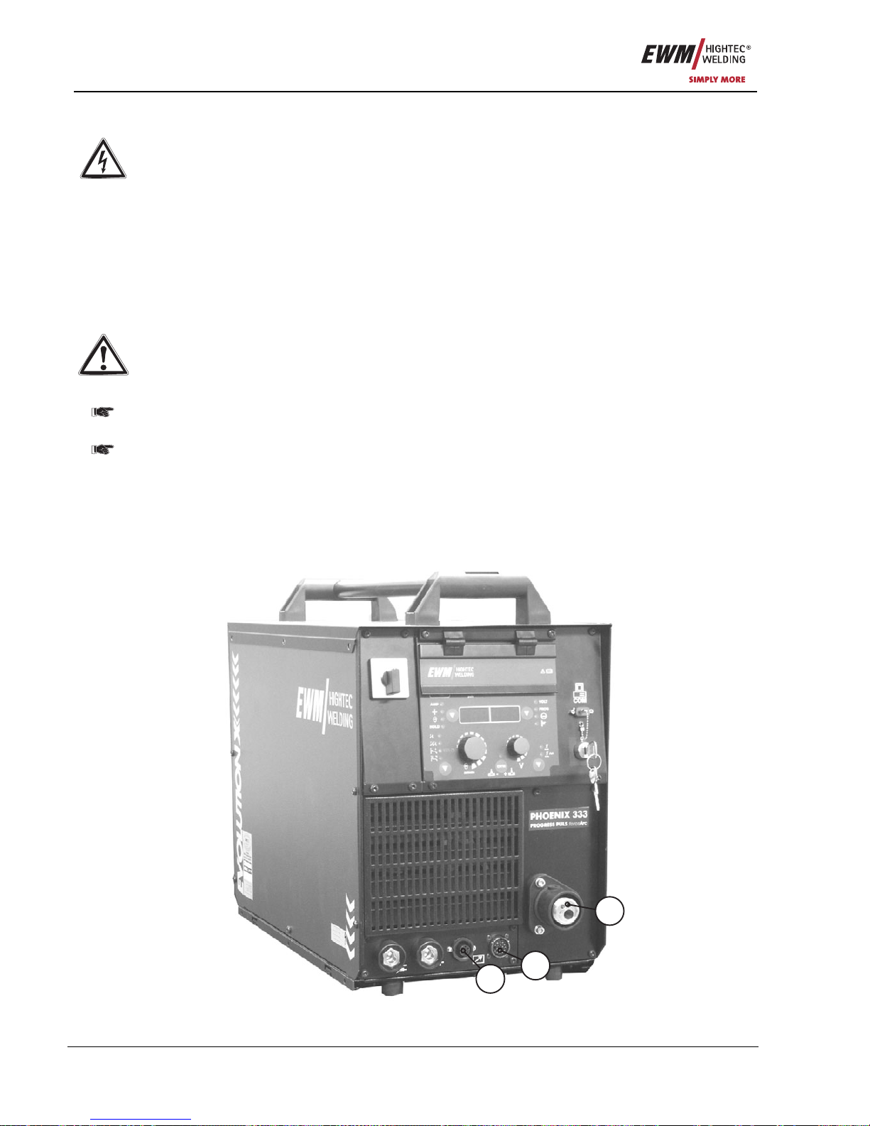
Commissioning
MIG/MAG welding
70 Item No.: 099-005073-EWM01
6.7 MIG/MAG welding
Warning – Risk from electrical current!
If welding is carried out alternately using different methods and if a welding torch and an
electrode holder remain connected to the machine, the open-circuit/welding voltage is applied
simultaneously on all cables. The torch and the electrode holder should therefore always be
placed on an insulated surface before starting work and during breaks.
Connection and welding leads (e.g. electrode holder, welding torch, workpiece lead, interfaces)
may only be connected when the machine is switched off.
Follow the safety instructions on the opening pages entitled “For Your Safety”!
We can only guarantee the perfect functioning of our machines when used with our range of
accessory components.
6.7.1 Welding torch connection
We can only guarantee correct functioning of our machines when used with our range of welding
torches.
The correct spirals or cores must be used for the relevant wire diameter and wire type.
Welding torch with insulatated liner:
A capillary tube must be installed in the central connection.
Welding torch with Teflon or plastic core:
The capillary tube must be removed from the central connection.
Preparing the welding torch for the welding task:
• Shorten the Teflon core and surrounding guide pipe so that the distance to the drive roller is as short
as possible.
• The Teflon core and the guide pipe must not be deformed.
• Deburr the Teflon core and the guide pipe.
2
3
1
Figure 6-2
Page 71
Commissioning
MIG/MAG welding
Item No.: 099-005073-EWM01 71
Item Symbol Description 0
1
Euro-central connector (welding torch connection)
Welding current, shielding gas and torch trigger included
2
19-pole connection socket (analogue)
For connecting analogue accessory components (remote control, welding torch control
lead, intermediate drive, etc.)
We can only guarantee correct functioning of our machines when used with our range of welding
torches.
The correct spirals or cores must be used for the relevant wire diameter and wire type.
Welding torch with insulatated liner:
A capillary tube must be installed in the central connection.
Welding torch with Teflon or plastic core:
The capillary tube must be removed from the central connection.
Preparing the welding torch for the welding task:
• Shorten the Teflon core and surrounding guide pipe so that the distance to the drive roller is as short
as possible.
• The Teflon core and the guide pipe must not be deformed.
• Deburr the Teflon core and the guide pipe.
• Insert 19-pole cable plug on the control lead into the 19-pole (analogue) connection socket and secure
with crown nut (the plug can only be inserted into the connection socket in one position).
Page 72
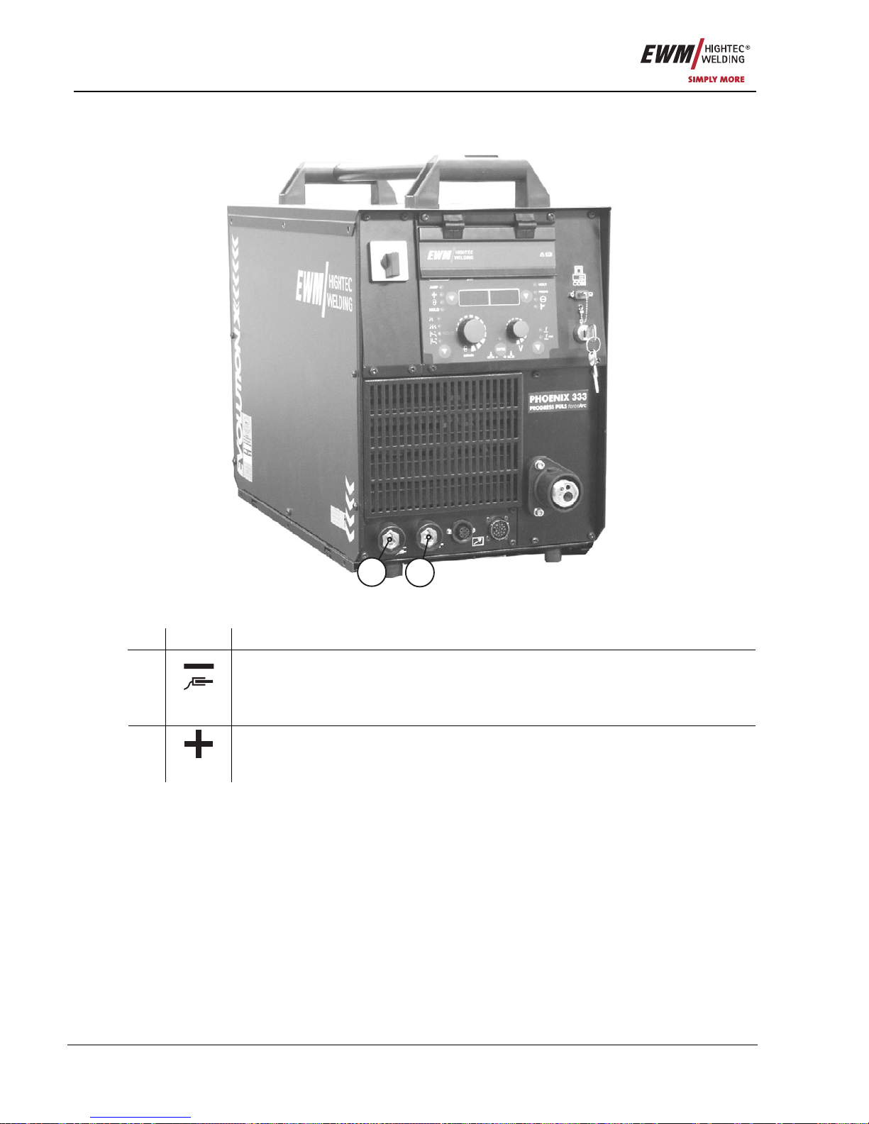
Commissioning
MIG/MAG welding
72 Item No.: 099-005073-EWM01
6.7.2 Connection for workpiece lead
2
1
Figure 6-3
Item Symbol Description 0
Connection socket, “-” welding current
• MIG/MAG welding: Workpiece connection
• MMA welding: Workpiece or electrode holder connection
1
• TIG welding: Welding current connection for welding torch
Connection socket, “+” welding current
• MMA welding: Workpiece or electrode holder connection
2
• TIG welding: Workpiece connection
• Insert cable plug on the workpiece lead into the "-" welding current socket and lock by turning to the
right.
Page 73
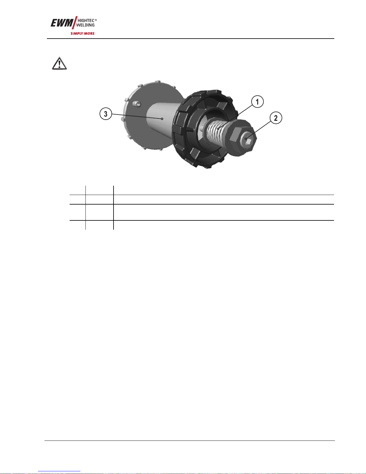
Commissioning
MIG/MAG welding
Item No.: 099-005073-EWM01 73
6.7.3 Fixing of the pin reel (adjustment of the pre-tensioning)
As the spool brake at the same time also secures the wire spool retainer, the following working
steps are to be carried out for every spool change and before every adjustment of the spool
brake.
Figure 6-4
Item Symbol Description 0
1 Securing and braking unit
2 Allen screw
Securing the wire spool retainer and adjustment of the spool brake
3 Spool holder retainer
• Loosen the Allen screw of the securing and braking unit till the screw comes out of the thread in the
spool holder retainer (but do not screw it out completely to prevent losing it).
• Pre-tension the securing and braking unit in the spool holder retainer by making at least 4 complete
turns of the Allen screw (4 x 360°) in the clockwise direction.
Page 74
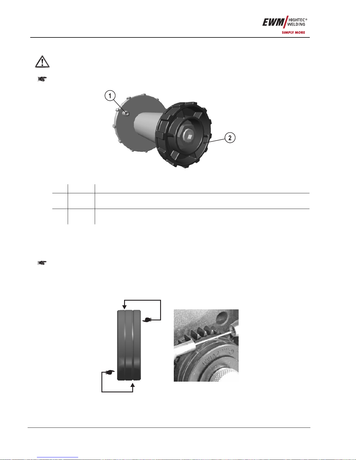
Commissioning
MIG/MAG welding
74 Item No.: 099-005073-EWM01
6.7.4 Inserting the wire spool
The pretensioning of the pin reel shall be checked before each wire spool replacement and before
the adjustment of the spool brake, see chapter on fixing of the pin reel (adjustment of the
pretensioning)!
Standard D300 pin reels can be used. Adapters (see accessories) are required when using
standardised basket coils (DIN 8559).
Figure 6-5
Item Symbol Description 0
1 Carrier pin
For fixing the wire spool
2 Knurled nut
For fixing the wire spool
• Loosen knurled nut from spool holder.
• Fix welding wire reel onto the spool holder so that the carrier pin locks into the spool bore.
• Fasten wire spool using knurled nut.
6.7.5 Changing the wire feed rollers
To ensure optimum wire feed, it is essential that the wire feed rollers match the wire electrode
diameter used (change if necessary).
The wire feed rollers are only suitable for two wire diameters (factory setting 0.8 mm or 1.0 mm).
Turning the WF rollers changes between the two wire diameters.
• Slide new drive rollers into place so that the diameter of the wire electrode printed on the wire feed
roller is visible. Screw the drive rollers in place with knurled screws.
Figure 6-6
Page 75
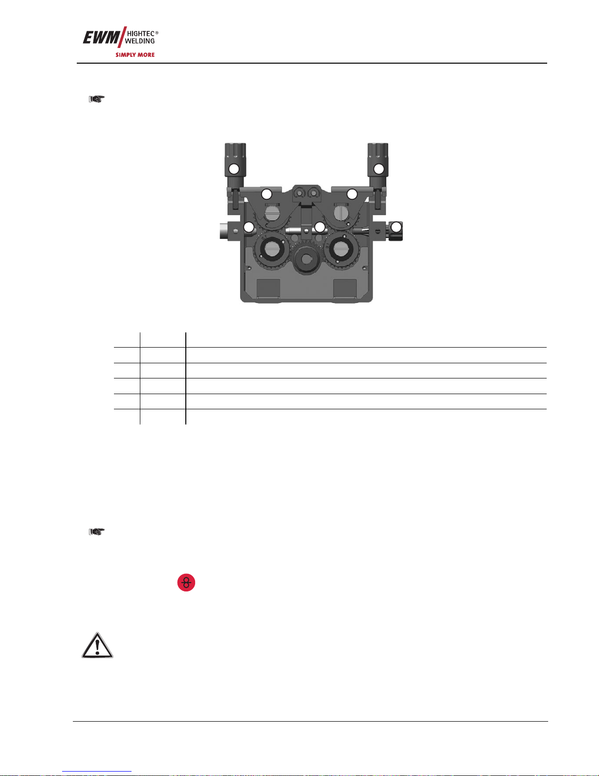
Commissioning
MIG/MAG welding
Item No.: 099-005073-EWM01 75
6.7.6 Inching the wire electrode
To ensure optimum wire feeding, it is essential that the wire feed rollers match the applied wire
electrode diameter and the type of material used (exchange if necessary).
Slide new drive rollers into place so that the diameter of the wire electrode printed on the wire
feed roller is visible. Screw the drive rollers in place with knurled screws.
11
2
345
2
Figure 6-7
Item Symbol Description 0
1 Pressure units
2 Clamping units
3 Wire inlet nipple
4 Guide tube
5 Capillary tube or Teflon core
• Extend and lay out the torch tube package.
• Unfasten pressure units and fold out (clamping units and counter-pressure rollers will automatically flip
upwards).
• Unwind welding wire carefully from the wire spool and insert through the wi re inlet nipple over the drive
roller grooves and the guide pipe into the capillary tube and Teflon core using guide pipe.
• Press the clamping element with the counter-roller back downwards and fold the wire units back up
again (wire electrode should in the groove on the drive roller).
The clamping pressure must be set on the adjusting nuts of the pressure units so that the wire
electrode is conveyed but will still slip through if the wire spool jams.
• Press the wire inching button until the wire electrode projects from the welding torch.
For wire feed units with control M3.70, the inching process is started directly on the control by
pressing the
key button.
The inching speed can be selected in two stages (ramp function), see also chap. Function
specification / special parameters.
Caution, risk of injury!
Never point welding torch at people or animals!
Page 76
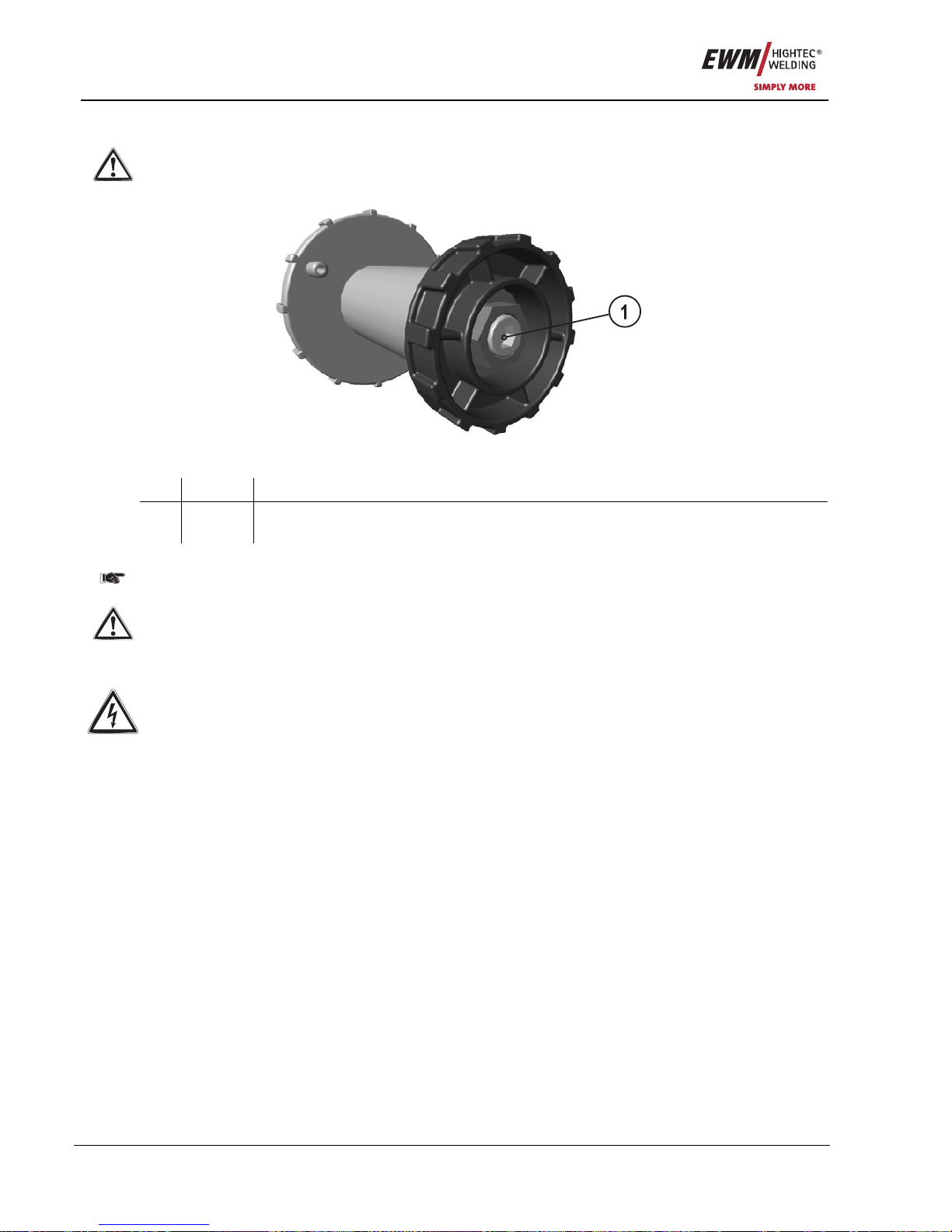
Commissioning
TIG welding
76 Item No.: 099-005073-EWM01
6.7.7 Spool brake setting
The pretensioning of the pin reel shall be checked before each wire spool replacement and before
the adjustment of the spool brake, see chapter on fixing of the pin reel (adjustment of the
pretensioning)!
Figure 6-8
Item Symbol Description 0
1 Allen screw
Securing the wire spool retainer and adjustment of the spool brake
• Tighten the Allen screw (8 mm) in the clockwise direction to increase the braking effect.
Tighten spool brake only to the point where the wire spool no longer runs on when the trigger
"wire inching" is released! The wire spool must not jam!
If the Allen screw is now loosened by as much as it was previously tightened, a renewed
tightening of the pin reel will be necessary, see chapter "Fixing of the pin reel (adjustment of the
pretensioning)".
6.8 TIG welding
Warning – Risk from electrical current!
If welding is carried out alternately using different methods and if a welding torch and an
electrode holder remain connected to the machine, the open-circuit/welding voltage is applied
simultaneously on all cables. The torch and the electrode holder should therefore always be
placed on an insulated surface before starting work and during breaks.
Connection and welding leads (e.g. electrode holder, welding torch, workpiece lead, interfaces)
may only be connected when the machine is switched off.
Follow the safety instructions on the opening pages entitled “For Your Safety”!
We can only guarantee the perfect functioning of our machines when used with our range of
accessory components.
Page 77
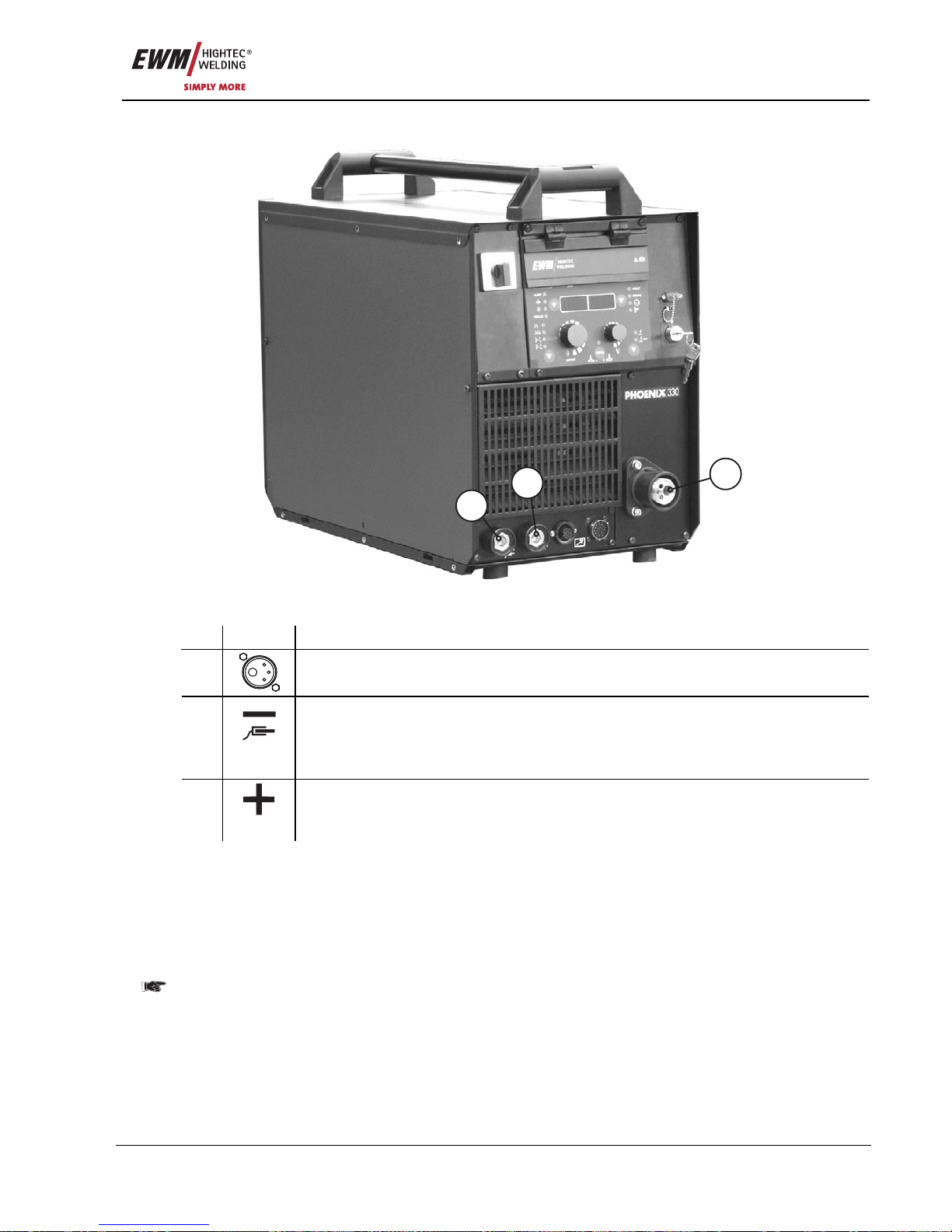
Commissioning
TIG welding
Item No.: 099-005073-EWM01 77
6.8.1 Welding torch connection
1
2
3
Figure 6-9
Item Symbol Description 0
1
Euro-central connector (welding torch connection)
Welding current, shielding gas and torch trigger included
Connection socket, “-” welding current
• MIG/MAG welding: Workpiece connection
• MMA welding: Workpiece or electrode holder connection
2
• TIG welding: Welding current connection for welding torch
Connection socket, “+” welding current
• MMA welding: Workpiece or electrode holder connection
3
• TIG welding: Workpiece connection
• Insert the central plug for the welding torch into the central connector and screw together with crown
nut.
• Insert central plug of the welding torch into the central connector and screw together with crown nut.
• Lock connecting nipples of the cooling water tubes into place in the corresponding rapid-action closure
couplings:
Return, red, to rapid-action closure coupling, red (coolant return) and
Return, blue, to rapid-action closure coupling, blue (coolant supply).
For the PHOENIX 330, the coolant hoses are connected directly to the cooling module.
• Insert the welding current plug on the combi torch into the “-” welding current connection socket and
lock by turning to the right.
• Insert the welding current plug on the welding torch into the welding current connection socket and
lock by turning to the right.
• Insert cable plug on the workpiece lead into the welding current socket “+” and lock by turning to the
right.
Page 78
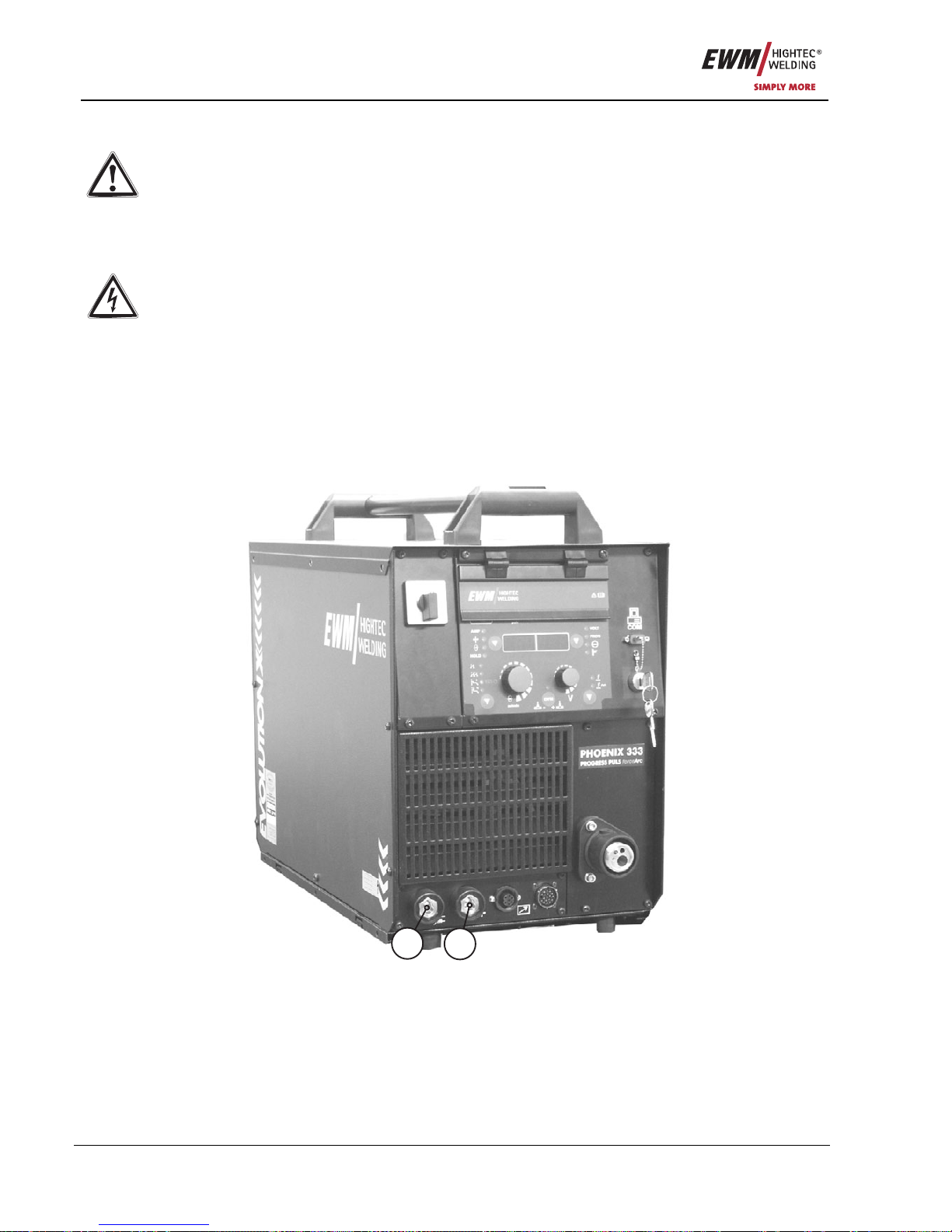
Commissioning
MMA welding
78 Item No.: 099-005073-EWM01
6.9 MMA welding
Caution: Risk of being crushed or burnt.
When replacing spent or new stick electrodes
• Switch off machine at the main switch
• Wear appropriate safety gloves
• Use insulated tongs to remove spent stick electrodes or to move welded workpieces and
• Always put the electrode holder down on an insulated surface.
Warning – Risk from electrical current!
If welding is carried out alternately using different methods and if a welding torch and an
electrode holder remain connected to the machine, the open-circuit/welding voltage is applied
simultaneously on all cables. The torch and the electrode holder should therefore always be
placed on an insulated surface before starting work and during breaks.
Connection and welding leads (e.g. electrode holder, welding torch, workpiece lead, interfaces)
may only be connected when the machine is switched off.
Follow the safety instructions on the opening pages entitled “For Your Safety”!
We can only guarantee the perfect functioning of our machines when used with our range of
accessory components.
2
1
Figure 6-10
Page 79

Commissioning
MMA welding
Item No.: 099-005073-EWM01 79
Item Symbol Description 0
Connection socket, “+” welding current
• MMA welding: Workpiece or electrode holder connection
1
• TIG welding: Workpiece connection
Connection socket, “-” welding current
• MIG/MAG welding: Workpiece connection
• MMA welding: Workpiece or electrode holder connection
2
• TIG welding: Welding current connection for welding torch
• Insert cable plug of the electrode holder into either the "+" or "-" welding current connection socket and
lock by turning to the right.
• Insert cable plug of the workpiece lead into either the "+" or "-" welding current connection socket and
lock by turning to the right.
Polarity depends on the instructions from the electrode manufacturer given on the electrode
packaging.
Page 80
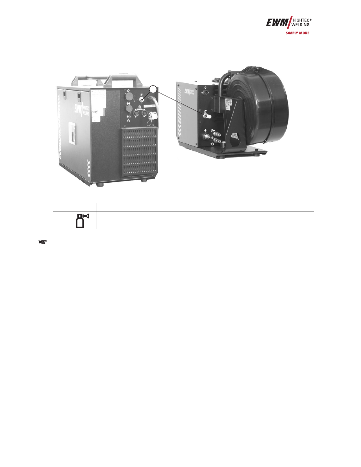
Commissioning
Shielding gas supply
80 Item No.: 099-005073-EWM01
6.10 Shielding gas supply
6.10.1 Connecting the shielding gas supply
1
Figure 6-11
Item Symbol Description 0
1
G¼” connecting nipple
Shielding gas connection on the pressure reducer
Before connecting the pressure reducer to the gas cylinder, open the cylinder valve briefly to
blow out any dirt.
• Place the shielding gas cylinder into the relevant cylinder bra cket.
• Secure the shielding gas cylinder using a securing chain.
• Tighten the pressure reducer screw connection on the gas bottle valve to be gas-tight.
• Tighten gas hose on pressure reducer to be gas tight.
• Screw the gas hose connection nipple onto the G¼" connection nipple.
Page 81
Commissioning
Shielding gas supply
Item No.: 099-005073-EWM01 81
6.10.2 Gas test
• Slowly open the gas cylinder valve.
• Open the pressure reducer.
• Switch on the power source at the main switch.
• Initiate gas test function on the machine control.
• Set the relevant gas quantity for the application on the pressure reducer.
6.10.3 “Rinse tube package” function
Operating
Element
Action Result
5 sec.
Select rinse tube package.
Shielding gas flows continuously until the Gas Test button is pressed
again.
6.10.4 Setting the shielding gas quantity
Welding process Recommended shielding gas quantity
MAG welding Wire diameter x 11.5 = l/min
MIG brazing Wire diamete r x 11.5 = l/min
MIG welding (aluminium) Wire diameter x 13.5 = l/min (100 % argon)
TIG Gas nozzle diameter in mm corresponds to l/min gas throughput
Notes on aluminium welding
A two-stage pressure reducer should always be used for aluminium welding.
A venturi for a gas flow of 0 -16 l/min is fitted on each wire feed unit as standard. For applications where a
higher gas flow rate is required (e.g. for aluminium), a venturi of 0 -25 l/min (see accessories) should be
used.
Consequences of incorrect shielding gas settings
• Insufficient shielding gas:
Inadequate gas protection, the indrawn air results in pores in the weld sea m.
• Excessive shielding gas:
Turbulence can be caused, allowing air to enter and cause pores in the weld seam.
Page 82
Maintenance and testing
General
82 Item No.: 099-005073-EWM01
7 Maintenance and testing
The maintenance, cleaning and testing work described below must be conducted correctly and on
an annual basis in order to be entitled to claim under the EWM warranty.
7.1 General
Under the indicated environmental conditions and normal operating conditions, this machine is largely
maintenance-free and requires minimum care. However, a number of points should be observed to
guarantee fault-free operation of your welding machine. Among these are regular cleaning and checking
as described below, depending on the level of contamination in the environment and the u sag e time of
the welding machine.
Cleaning, testing and repairing of the welding machines may only be carried out by competent,
capable personnel. A capable person is one who, due to training, knowledge and experience, is
able to recognise the dangers that can occur during testing of welding power sources as well as
possible subsequent damage and who is able to implement the required safety procedures.
In the event of failure to comply with any one of the following tests, the machine must not be
operated again until it has been repaired and a new test has been carried out.
7.2 Cleaning
Before cleaning, carefully disconnect the machine from the mains. DISCONNECT THE MAINS
PLUG!
(Switching off or removing the fuse does not provide adequate insulation protection.)
Wait 2 minutes until the capacitors are discharged. Remove the casing cover.
The individual components should be handled as follows:
Power source:
Depending on the amount of dust, blow out using oil- and moisture-free compressed air.
Electronics: Do not blast electronic components or circuit boards with compressed air but instead use
suction from a vacuum cleaner for cleaning purposes.
Coolant:
Check for impurities and replace if necessary.
Caution! Mixing with other liquids or the use of other coolants voids our
manufacturer's guarantee.
7.3 Test
The test should be conducted in accordance with IEC/DIN EN 60974-4 "Arc welding equipment –
Inspection and testing during operation" in accordance with the German Ordinance of Operational Safety.
This standard is firstly, international, and secondly, specific to arc welding equipment.
The former term of repetition test has been replaced due to a change in the corresponding
standard with "Inspection and testing during operation".
In addition to the regulations on the test given here, the relevant local laws and regulations must
also be observed.
7.3.1 Test equipment
Due to the special conditions of inverter arc welding equipment, not all test equipment is suitable
for testing in accordance with VDE 0702 to the full extent!
EWM as a manufacturer offers all appropriately trained and authorised EWM sales partners the
appropriate test equipment and measuring devices conforming to VDE 0404-2, which eval uate the
frequency response conforming to DIN EN 61010-1 Appendix A – Measuring Circuit A1.
You as the user are tasked with ensuring that your EWM machines conform to the standard IEC/DIN EN
60974-4 and are tested with the relevant test equipment and measuring devices given above.
The following description of the test is only a brief overview of the products to be tested. For
details on the test points or in the event of any queries, please refer to IEC/DIN EN 60974-4.
Page 83
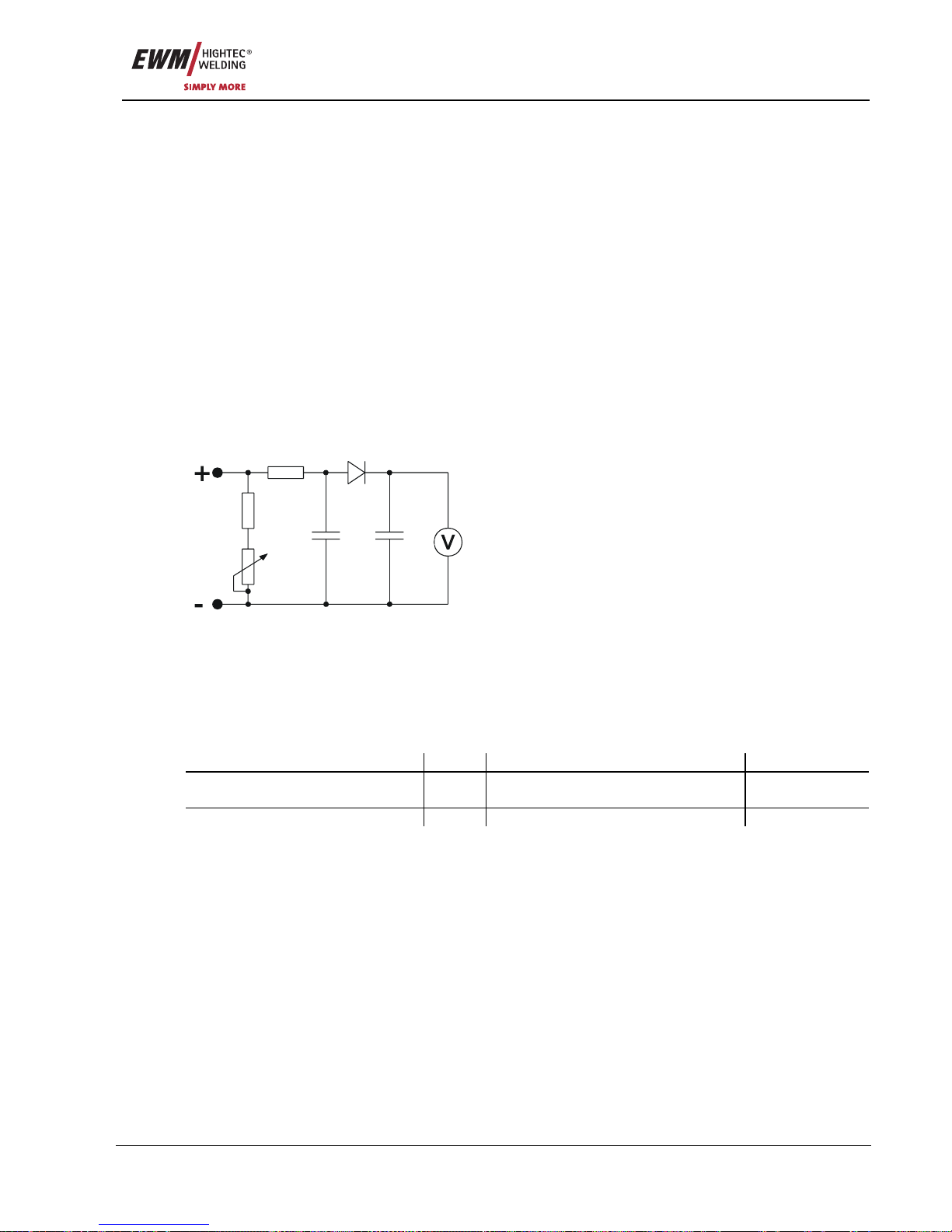
Maintenance and testing
Test
Item No.: 099-005073-EWM01 83
7.3.2 Scope of the test
a) Visual inspection
b) Electrical test: measurement of
• open circuit voltage
• insulation resistance, or alternatively
• leakage currents
• protective conductor resistance
c) Functional test
d) Documentation
7.3.3 Visual inspection
The key areas in the test are:
1. Torch/stick electrode holder, welding current return lead clamp
2. Power supply: leads including plugs and strain relief
3. Welding current circuit: leads, plugs and couplings, strain relief
4. Casing
5. Operating, message, safety and adjustment devices
6. Other, general condition
7.3.4 Measuring the open circuit voltage
6u8F
10nF
0...5k
0k2
1k0
1N 4007
Measuring circuit according to DIN EN
60974-1
Connect the measuring circuit to the welding current
sockets. The voltmeter must display mean values and
have an internal resistance ≥ 1 MΩ. In the case of step
switch controlled devices, set the maximum output voltage
(step switch). Adjust the potentiometer from 0 kΩ to 5 kΩ
during the measurement. The measured voltage should
not deviate from that specified on the rating plate by more
than +/- 5% and may be no greater than 113 V (for devices
with VRD: 35 V).
7.3.5 Measurement of insulation resistance
The mains switch must be on so that the insulation in the interior of the machine can also be checked
through to the transformer. If a mains contactor is fitted, this should be bridged or the measurement must
be carried out on both sides.
The insulation resistance must not be less than:
Mains current circuit against Welding current circuit and electronics
5 MΩ
Welding current circuit and
electronics
against Protective conductor circuit (PE)
2.5 MΩ
Mains current circuit against Protective conductor circuit (PE)
2.5 MΩ
Page 84

Maintenance and testing
Test
84 Item No.: 099-005073-EWM01
7.3.6 Measuring the leakage current (protective conductor and contact current)
Note: Even if the leakage current measurement according to the standard is only an alternative to the
insulation resistance measurement, EWM recommends always performing both measurements,
especially following repair work. The leakage current is based for the greater part on a physical effect
other than the insulation resistance. For this reason, it may not be possible to uncover a dangerous
leakage current using the insulation resistance measurement.
These measurements cannot be performed with a normal multimeter. Even test devices for VDE 0702
(especially older devices) are generally only intended for 50/60Hz. With inverter welding machines,
however, significantly higher frequencies occur, which can interfere with some measuring devices, and
result in others measuring the frequency incorrectly.
A test device must meet the requirements of VDE 0404-2. For the frequency response measurement,
please refer to DIN EN 61010-1 Appendix A – Measuring circuit A1.
For these measurements the welding machine must be switched on and supplying open circuit
voltage.
1. Protective conductor current: < 5mA
2. Leakage current from the welding sockets separately to PE: < 10mA
7.3.7 Measurement of protective conductor resistance
Measure between the plug earthed contact and accessible live parts, e.g. casing screws.
During the measurement, the connection lead must be moved across the entire length, especially near
the casing and plug inlet points. This should uncover any interruptions in the pro t ective conductor. All
conductive parts of the casing accessible from outside should also be tested to ensure a correct PE
connection for safety class I.
The resistance must not exceed a mains connection lead 0.3Ω up to 5m in length. For longer leads, the
permissible value increases by 0.1Ω per 7.5m of lead. The maximum permissible value is 1Ω.
7.3.8 Functional test of the welding machine
Safety devices, selector switches and command units (if fitted) and the entire machine or the entire
system for arc welding, must be functioning perfectly.
1. Main switch
2. Emergency stop devices
3. Voltage reducing device
4. Gas solenoid valve
5. Message and control lamps
7.3.9 Documentation of the test
The test report must contain:
• the designation of the tested welding equipment,
• the date of the test,
• the test results,
• the signature, name of technician and the relevant institution,
• the name of the test equipment.
A label with the date of the test must be affixed to the welding machine to show that the test has been
passed.
Page 85
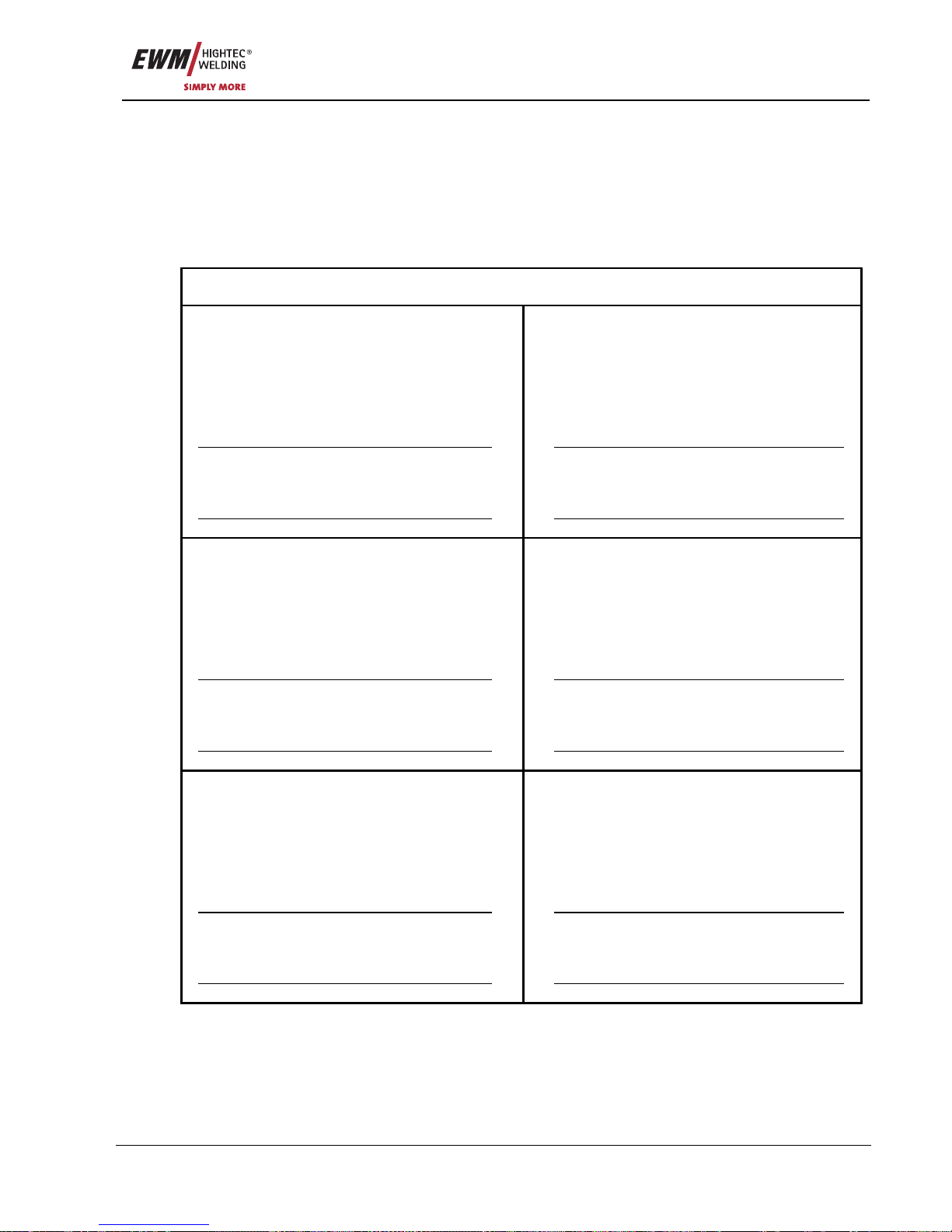
Maintenance and testing
Repair Work
Item No.: 099-005073-EWM01 85
7.4 Repair Work
Repair and maintenance work may only be performed by qualified authorised personnel; otherwise the
right to claim under the warranty is void. In all service matters, please contact your EMW sales partner.
Returns of defective equipment subject to warranty may only be made through your EWM sales partner.
In the event of problems or queries, please contact the EWM Service Department directly (+49 (0) 2680
181 0). Use only genuine spare parts and replacement parts when replacing. When placing an order,
please quote the type designation and item number, as well as the type, serial number and item number
of the relevant equipment.
We hereby confirm that the servicing and maintenance instructions given above and the test described above have
been completed correctly.
Date/Stamp/Signature of EWM sales partner
Date/Stamp/Signature of EWM sales partner
Date of next maintenance work and test
Date of next maintenance work and test
Date/Stamp/Signature of EWM sales partner
Date/Stamp/Signature of EWM sales partner
Date of next maintenance work and test
Date of next maintenance work and test
Date/Stamp/Signature of EWM sales partner
Date/Stamp/Signature of EWM sales partner
Date of next maintenance work and test
Date of next maintenance work and test
Page 86

Maintenance and testing
Disposing of equipment
86 Item No.: 099-005073-EWM01
7.5 Disposing of equipment
This machine does not belong in household waste, in accordance with the German Law on
Electrical Equipment Waste.
In Germany, waste equipment from private households can be disposed of free of charge at local
community collection points. Your administrative office will be pleased to inform you of the options.
EWM participates in an approved waste disposal and recycling system and is registe red in th e Used
Electrical Equipment Register (EAR) under number WEEE DE 57686922.
In addition, within Europe the machine can also be returned to your EWM sales partner.
7.5.1 Manufacturer's declaration to the end user
• In accordance with European guidelines (Directive 2002/96/EC from the European Parliament and the
Council of 27.01.03), it is no longer permissible to dispose of used electrical and electronic equipment
in unsorted household waste collections. It must be kept separate from other waste. The symbol on
the wheeled bins indicates the requirement to separate this waste.
Help to protect the environment and ensure that this equipment, when you no longer want to use it, is
disposed of in the relevant system of separated waste disposal.
• In Germany, (German Law on the Distribution, Return and Environmentally-Friendly Dispo sal of
Electrical and Electronic Equipment (ElektroG) of 16.03.05) you are required to take old equipment to
a waste collection point separated from household waste. The public waste disposal contractor (local
authorities) have set up collection points for this purpose where old equipment from private
households in your area can be collected for you free of charge.
It is also possible that the legally responsible waste disposal company will collect old equipment from
private households.
• Please obtain the relevant information from your local waste calendar or from your town council or
local authority on the options available in your area for returning or collecting old equipment.
7.6 Meeting the requirements of RoHS
We, EWM HIGHTEC Welding GmbH Mündersbach, hereby co nfirm that all products supplied by us which
are affected by the RoHS Directive, meet the requirements of the RoHS (Directive 2002/95/EC).
Page 87
Warranty
General Validity
Item No.: 099-005073-EWM01 87
8 Warranty
8.1 General Validity
3-year warranty
on all new EWM machines*:
• Power sources
• Wire feeds
• Cooling units
• Trolleys
* If these are operated with genuine EWM accessories (such as intermediate tube package, remote
control, remote control extension cable, coolant, etc.).
1-year warranty on:
• Used EWM machines
• Automation and mechanisation components
• Remote control
• Inverters
• Intermediate tube packages
6-month warranty on:
• Spare parts supplied separately (such as circuit boards, ignition units)
Manufacturer/supplier warranty on:
• All additional parts used by EWM, but manufactured by other companies (e.g. motors, pumps, fans,
torches, etc.)
Non-reproducible software errors and parts subject to mechanical ageing are excluded from the warranty
(e.g. wire feed unit, wire feed rollers, replacement and spare wire feed parts, wheels, solenoid valves,
workpiece leads, electrode holders, connection tubes, replacement torche s and spare torch parts, mains
and control leads, etc.).
These terms shall apply without affecting the customer’s legal righ ts to a warranty and subject to our
General Terms and Conditions of Business and our terms on the warranty declaration. Agreements to the
contrary must be confirmed by EWM in writing.
Our General Terms and Conditions of Business are available for access anytim e online at
www.ewm.de.
Page 88

Warranty
Warranty Declaration
88 Item No.: 099-005073-EWM01
8.2 Warranty Declaration
Your 3-year warranty
Regardless of statutory warranty rights and based on our General Terms and Conditions, EWM
HIGHTEC WELDING GmbH provides a 3-year warranty for its welding products starting on the date of
purchase. Different warranty periods apply to accessories and spare parts; please see the “General
Validity” section for these periods. Parts subject to wear are naturally exempt from the warranty.
EWM guarantees the error-free condition of the products in terms of materials and processing. If the
product proves to be defective in terms of materials or processing within the warranty period, you are
entitled to free repair or to replacement with an appropriate product, at our discretion. On receipt by EWM
the returned product becomes the property of EWM.
Condition
The prerequisite for receiving the full 3-year warranty is simply to operate the products in accordance with
the EWM operating instructions observing the relevant legal recommend ations and guidelines and having
annual maintenance work and testing conducted by an EWM sales partner (see “Maintenance and
testing” chapter). This is because only machines that are maintained regularly function correctly in the
long term.
Making a claim
When making a claim under the warranty, please contact your EWM authorised sales pa rtner only.
Warranty exclusions
No warranty claims can be accepted if the EWM products in question are not operated using genuine
EWM accessories (such as intermediate tube package, remote control, remote control e xten sion cable,
coolant, etc.). The warranty does not apply to products that are damaged due to accidents, misuse,
improper operation, incorrect installation, use of force, disregard of the specifications and operating
instructions, inadequate maintenance (see chapter “Maintenance and testing”), exterior influences, acts of
God or personal misfortunes. Furthermore, it is not valid in the case of improper changes, repairs or
modifications. In addition, a claim for warranty does not exist in the case of partially or completely
dismantled products and interventions by persons who are not authori se d by EWM, as well as in the case
of normal wear.
Limitation
All claims regarding fulfilment or non-fulfilment on the part of EWM from this declaration in connection
with this product are limited as follows to the replacement of the actual damages. EWM’s liability
stemming from this declaration in connection with this product is fundamentally limited to the amount that
the purchaser originally paid for the original purchase. This limitation does not apply to personal injuries
or damage to property caused by negligent behaviour on the part of EWM. In no way will EWM be
responsible for lost profits, indirect or subsequent damage. EWM is not liable for dama ge s ba sed on the
claims of third parties.
Place of jurisdiction
If the person making the claim is a business person, the sole place of jurisdiction for all disputes resulting
directly or indirectly from the contractual relationship shall be the headquarters or the branch office of the
supplier, at the discretion of the supplier. The purchaser gains ownership of the products supplied as
replacements within the framework of the warranty adjustment at the time of the exchange.
Page 89
Operating problems, causes and remedies
Error messages (power source)
Item No.: 099-005073-EWM01 89
9 Operating problems, causes and remedies
9.1 Error messages (power source)
All machines are subject to rigorous production and final checks. If, despite this, anything fails to work at
any time, please check machine using the chart below. If none of the fault rectification procedures
described leads to the correct functioning of the machine, please inform your authorised dealer.
A welding machine error is indicated by an error code being displayed (see table) on the display
on the machine control.
In the event of a machine error, the power unit is shut down.
• If multiple errors occur, these are displayed in succession.
• Document machine errors and inform service staff as necessary.
Category
Error
a) b) c)
Possible cause Remedy
Error 1
(Ov.Vol)
- - x Mains – excess voltage
Error 2
(Un.Vol)
- - x Mains – undervoltage
Check the mains voltages and compare with
the welding machine connection (see
Technical data, chapter 1)
Error 3
(Temp)
x - - Welding machine - excess
temperature
Allow the machine to cool down (main switch
to “1”)
Error 4
(Water)
- - x Coolant level low Top up the coolant
Leak in the coolant circuit > rectify the leak
and top up the coolant
Coolant pump is not working > check excess
current release on air cooling unit
Error 5
(Wi.Spe)
- x - Error in WF case, tachometer
error
Check the wire feed unit
Tachometer generator not issuing a signal,
M3.00 defective > information service dept.
Error 7
(Se.Vol)
- - x Secondary excess voltage Inverter error > inform Service
Error 8
(no PE)
- - x Earth fault between welding
wire and earth line
(PHOENIX 300 only)
Separate the connection between the
welding wire and case or an earthed object
Error 9
(fast
stop)
x - - Fast shut-down triggered by
BUSINT X10 or RINT X11
Rectify error on robot
Error 10
(no arc)
- x - Arc interruption
Fast shut-down triggered by
BUSINT X10 or RINT X11
Check wire feed
Error 11
(no ign)
- x - Ignition error after 5 seconds
Triggered by BUSINT X10 or
RINT X11
Check wire feed
Page 90
Accessories, options
General accessories
90 Item No.: 099-005073-EWM01
10 Accessories, options
10.1 General accessories
Type Designation Item no.
COOL71 U43 Cooling unit with centrif. pump and reinforced
cooling
090-008220-00102
TROLLY 75 B1 Transport vehicle, assembled for
power source + 1 module + 1 gas bottle
090-008176-00001
AK300 Adapter for K300 basket coil 094-001803-00001
DM1 32L/MIN Manometer pressure reducer 094-000009-00000
G1 2M G1/4 R 2M Gas hose 094-000010-00001
GS16L G1/4" SW 17 Pilot static tube 094-000914-00000
GS25L G1/4" SW 17 Pilot static tube 094-001100-00000
5POLE/CEE/16A/M Machine plug 094-000712-00000
WK50QMM 4M KL Workpiece cable, clamp 092-000003-00000
MIG 40 G 3M MIG welding torch, gas 094-003415-00000
MIG 452 W 4M HDH MIG welding torch, water flex. 094-011056-00104
EH50 4M Electrode holder 092-000004-00000
10.2 Remote control / connection cable
Type Designation Item no.
PHOENIX R10 Remote control with WF speed correction 090-008087-00000
RA5 19POL 5M Remote control e.g. connection cable 092-001470-00005
RA10 19POL 10M Remote control e.g. connection cable 092-001470-00010
RA20 19POL 20M Remote control e.g. connection cable 092-001470-00020
PHOENIX R20 Program changeover remote control 090-008263-00000
PHOENIX R40 Remote control, 10 programs 090-008088-00000
FRV5-L 7POL Extension/connecting cable 092-000201-00003
FRV10-L 7POL Extension/connecting cable 092-000201-00000
FRV20-L 7POL Extension/connecting cable 092-000201-00001
Page 91

Accessories, options
Wire feed rollers
Item No.: 099-005073-EWM01 91
10.3 Wire feed rollers
10.3.1 V-Nut wire conveyors
Type Designation Item no.
FE 2DR4R 0,6+0,8 Drive rollers, 37mm, 4-roller, steel 092-000839-00000
FE 2DR4R 0,8+1,0 Drive rollers, 37mm, 4-roller, steel 092-000840-00000
FE 2DR4R 0,9+1,2 Drive rollers, 37mm, 4-roller, steel 092-000841-00000
FE 2DR4R 1,0+1,2 Drive rollers, 37mm, 4-roller, steel 092-000842-00000
FE 2DR4R 1,2+1,6 Drive rollers, 37mm, 4-roller, steel 092-000843-00000
FE/AL 2GR4R Counterpressure rollers, smooth, 37mm 092-000844-00000
10.3.2 U-Nut wire conveyors
Type Designation Item no.
AL 4ZR4R 0,8+1,0 Twin wire feed rollers, 37mm, 4-rollers, for
aluminium
092-000869-00000
AL 4ZR4R 1,0+1,2 Twin wire feed rollers, 37mm, 4-rollers, for
aluminium
092-000848-00000
AL 4ZR4R 1,2+1,6 Twin wire feed rollers, 37mm, 4-rollers, for
aluminium
092-000849-00000
AL 4ZR4R 2,4+3,2 Twin wire feed rollers, 37mm, 4-rollers, for
aluminium
092-000870-00000
10.3.3 Wire feed rollers for cored wire
Type Designation Item no.
ROE 2DR4R 0,8/0,9+0,8/0,9 Drive rollers, 37mm, 4-roller, cored wire 092-000834-00000
ROE 2DR4R 1,0/1,2+1,4/1,6 Drive rollers, 37mm, 4-roller, cored wire 092-000835-00000
ROE 2DR4R 1,4/1,6+2,0/2,4 Drive rollers, 37mm, 4-roller, cored wire 092-000836-00000
ROE 2DR4R 2,8+3,2 Drive rollers, 37mm, 4-roller, cored wire 092-000837-00000
ROE 2GR4R Counterpressure rollers, knurled, 37mm 092-000838-00000
10.3.4 Conversion sets
Type Designation Item no.
URUE VERZ>UNVERZ FE/AL
4R
Conversion kit, 37mm, 4-roller drive on non-toothed
rollers (steel/aluminium)
092-000845-00000
URUE AL 4ZR4R 0,8+1,0 Conversion kit, 37mm, 4-roller drive for aluminium 092-000867-00000
URUE AL 4ZR4R 1,0+1,2 Conversion kit, 37mm, 4-roller drive for aluminium 092-000846-00000
URUE AL 4ZR4R 1,2+1,6 Conversion kit, 37mm, 4-roller drive for aluminium 092-000847-00000
URUE AL 4ZR4R 2,4+3,2 Conversion kit, 37mm, 4-roller drive for aluminium 092-000868-00000
URUE ROE 2DR4R
0,8/0,9+0,8/0,9
Conversion kit, 37mm, 4-roller drive for cored wire 092-000830-00000
URUE ROE 2DR4R
1,0/1,2+1,4/1,6
Conversion kit, 37mm, 4-roller drive for cored wire 092-000831-00000
URUE ROE 2DR4R
1,4/1,6+2,0/2,4
Conversion kit, 37mm, 4-roller drive for cored wire 092-000832-00000
URUE ROE 2DR4R 2,8+3,2 Conversion kit, 37mm, 4-roller drive for cored wire 092-000833-00000
Page 92

Accessories, options
Options
92 Item No.: 099-005073-EWM01
10.4 Options
Type Designation Item no.
MIG PP 24D POTI G 8M MIG welding torch, gas, push/pull 094-003419-00000
MIG 36 2U/D G 3M MIG welding torch, gas, Up/Down 094-007791-00000
POWERCONTROL 36
U/DLED G 3M
MIG welding torch, gas, Up/Down, with display 094-007790-00000
MIG PP 401D W 8M MIG welding torch, water cooled, push/pull 094-003420-00000
MIG PP 401D POTI W 8M MIG welding torch, water cooled, push/pull 094-003418-00000
MIG 452W 4M19PB2UD HF
EZA
MIG welding torch, water flex., 2xU/D 094-011056-00304
MIG 452W 4M19PBPC HF
EZA
MIG welding torch, POWERCONTROL, water flex. 094-011056-00404
ON SET KRAN HOR Optional retrofitting of PHOENIX horizontal traverse
suspension
092-001832-00000
ON SET CRANE HOR/VER Optional retrofit kit for horizontal/vertical crane
suspension
092-002355-00000
ON A INTERFACE Option retrofit for analog mech. welding interface
PHOENIX PROGRESS
092-001779-00000
ON WHEELS PHOENIX
303/330/333
Optional retrofit wheel set for PHOENIX
303/330/333 machine series
092-002387-00000
10.5 Computer communication
Type Designation Item no.
PC300.NET PC300.Net welding parameter software set incl.
cable and SECINT X10 USB interface
090-008265-00000
CD-ROM PC300.NET PC300.Net Update on CD-ROM 092-008172-00001
WELDQAS1 Mobil Stationary welding data monitoring and docu set for
one welding machine
090-008214-00000
WELDQAS2 Mobil Mobile welding data monitoring and docu set for two
welding machines
090-008217-00000
FRV5-L 7POL Extension/connecting cable 092-000201-00003
FRV10-L 7POL Extension/connecting cable 092-000201-00000
FRV20-L 7POL Extension/connecting cable 092-000201-00001
PC INTX10 SET Q-DOC 9000 documentation interface 090-008093-00000
PCV10-L 10M 9POL Cable between PC/interface 094-001206-00002
Page 93
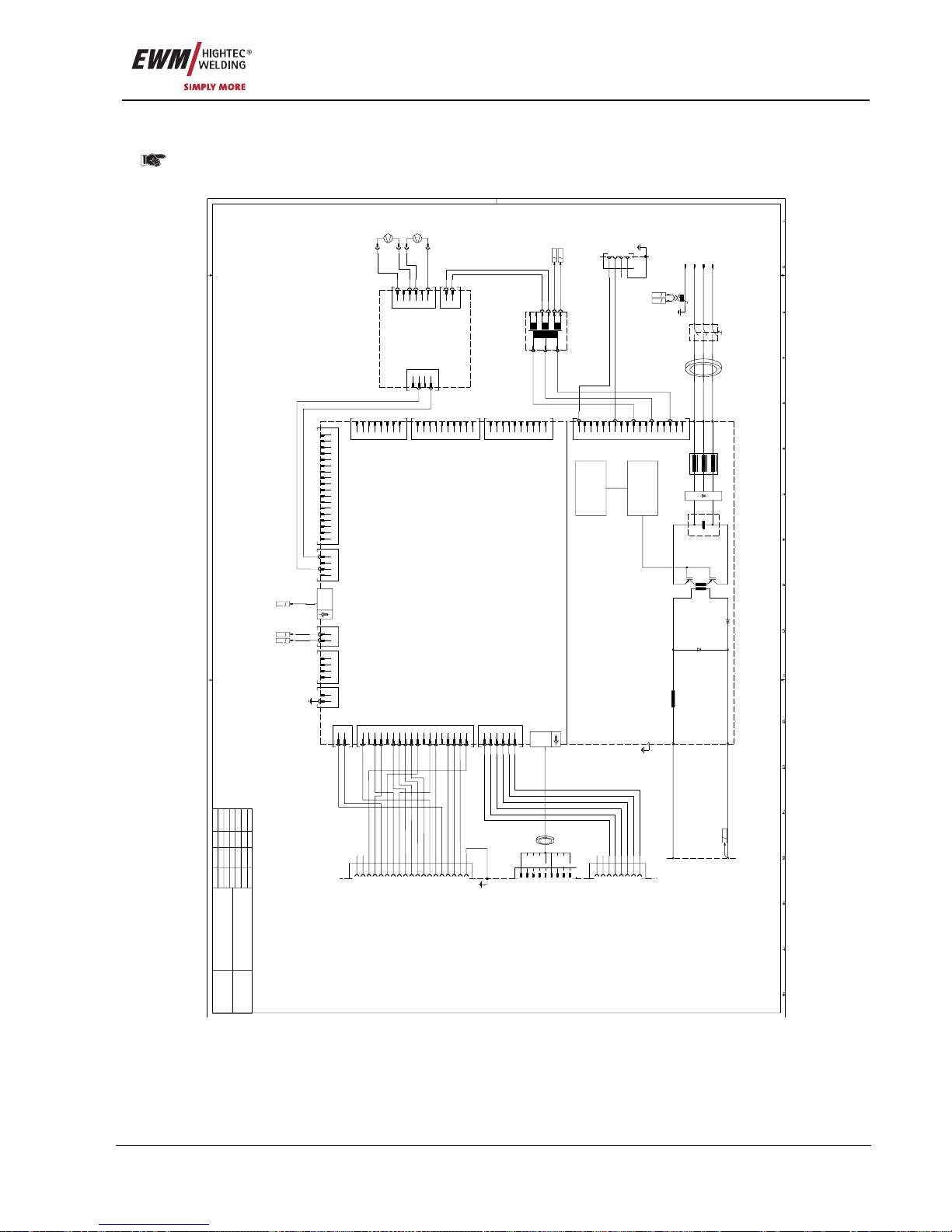
Circuit diagrams
PHOENIX 333 PROGRESS KG
Item No.: 099-005073-EWM01 93
11 Circuit diagrams
Original format circuit diagrams are located inside the machine.
11.1 PHOENIX 333 PROGRESS KG
X7/10
X7/11
X7/12
X7/13
X7/14
X7/15
X7/16
X7/17
X7/18
X7/1
X7/2
X7/3
X7/4
X7/5
X7/6
X7/7
X7/8
X7/9
L1L2L3
ZWK2
TRI
A3
SPW6
WIG
PE
-
+
A1-
D C 3 0 0
L1L1L2L2L3
L3
PE
PE
Q1-
L1L2L3
T1T2T3
A1-L1
A1-L2
A1-L3
Ringkern
n=2Wdg.
3
400VAC6230VAC
9
0VAC
12
400VAC
18
0VAC
X1-
PE12
3
PE
8/9
6/7
17/18
14/15
10/11
T1-
AB3/4
1/2
A
42V
B
0V
17/18
400V
14/15
230V
10/11
0V
+
-
Frontseite
A1-
+
PE-
T?
A
3 4B3 4
X3/1
X3/2
X3/3
X3/4
X3
X1/1
X1/2
X1
X3/5
X3/6
X2/1
X2/2X2X2/3
X2/4
A3-
L D C 1
1
Lüfter
3
Lüfter
1
Lüfter3Lüfter
1
0VAC
2
20VAC
1
24VDC
3
0VDC
4
24VDC
6
0VDC
1~
Lüfter
M1-
+
-
1~
Lüfter
M2-
+
-
E
2 13
F 83
1
Pumpe2Lüfter3+15V4Wassermangel5Wasserkühler60V
ABCDEFG
H
Pumpe
Lüfter
+15V
Wassermangel
Wasserkühler
0V
NC
NC
X3-
X2-
2345678
9
1
NC
PC-RXD
PC-GND
NC
NC
PC-TXD
PC-DTR
PC-RTS
NC
1
Iist2REGaus3SYN_E4IGR060V7+15V9IGR010Uist11VSchweiss12SYN_A13Start/Stop150V16-15V18IGR01Not/Aus2Not/Aus
Rückseite
1
PE5-
PE
X1/10
X1/11
X1/12
X1/13
X1/14
X1/15
X1/16
X1/17
X1/18
X1/1
X1/2
X1/3
X1/4
X1/5
X1/6
X1/7
X1/8
X1/9
X2/1
X2/2
X2/3
X2/4
X-PE/1
X-PE/2
X4/1
X4/2
X4/3
X4/4
X10/1
X10/2
D-Sub.
15polig
Inverter sekundär Lüfter System-Bus
X1 X2 X8
Fühlerspannung
X10
Versorgung
X4 X-PE
PE
X9/1
X9/2
X9/3
X9/4
X9/5
X9/6
X9
D-Sub.
X5/1
X5/2
X5/3
X5/4
X5/5
X5/6
X5/7
X5/8
X5/9
X5
Robo./Auto.
X5/10
X5/11
X5/12
X5/13
X5/14
X5/15
X5/16
X5/17
X5/18
X6/2
X6/1
Wasserkühler
Computer
X7
Not-Aus
X6
X3/1
X3/2
X3/3
X3/4
X3/5
X3/6
X3/7
X3/8
X3
X11/1
X11/2
X11/3
X11/4
X11/5
X11/6
X11/7
X11/8
X11/9
X11/10
X20/1
X20/2
X20/3
X20/4
X20/5
X20/6
X20/7
X20/8
X20/9
X20/10
X11
X20
Inverter primär
M 3 2 0
A2-
9polig
ABCDEFGHJKLMNPRSTUV
PE
REGaus
SYN_E
IGR0
Not/Aus
0V
IGR0
Uist
VSchweiss
SYN_A
Start/Stop
+15V
-15V
IGR0
Not/Aus
0V
Iist
NC
NC
X4-
8/9
20V
6/7
0V
1
PE
Rückseite
C
92
D
102
1
Fühlerspannung
2
Fühlerspannung
G 63
H 73
Ringkern
1Wdg.
1
PE
Datum: Name:
gezeichnet:
geprüft:
Freigabe:
10.10.2007 NIEDENTHAL
Blatt: /3
This drawing is protected by copyright.
It may not be reproduced or utilised in any way
or communicated or forwarded to third parties
without our express permission!
1
PHOENIX 333 PROGRESS
5034-00
Zeichnungsnummer:
WIG-GERAET, 3X400V FAHRBAR
Änderung-
Änderung-
Änderung-
Änderung-
Figure 11-1
Page 94
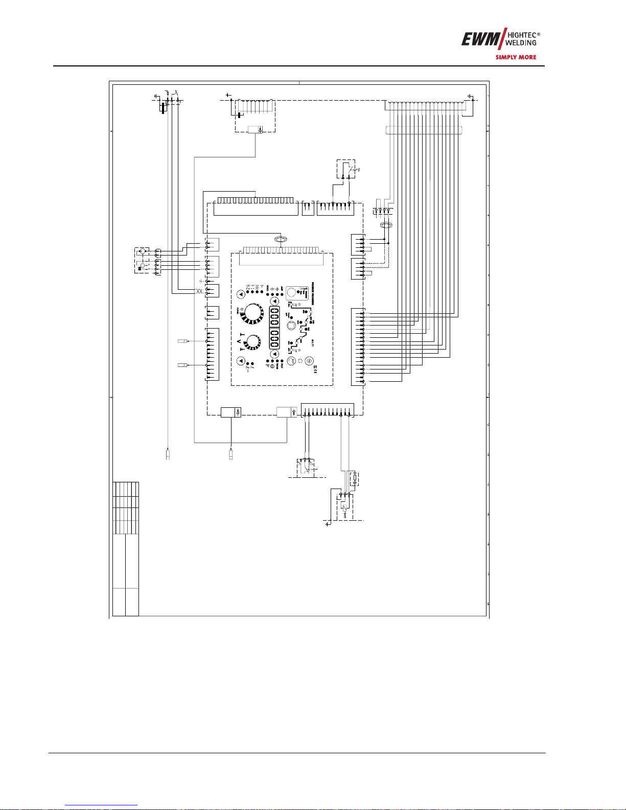
Circuit diagrams
PHOENIX 333 PROGRESS KG
94 Item No.: 099-005073-EWM01
A
B
C
D
E
F
G
H
J
K
L
M
NPR
S
T
U
V
NC
LED-A
+10V
DV(UP)0VBRT
US(DOWN)
LED-G
LED-D
LED-E
Code UP
LED-B
LED-C
Code DV
Code US
BRT
LED-F
Motor -
Motor +
X5-
Ringkern
1
+10V
2
LED-A
3
LED-B
4
LED-C
5
LED-D
6
LED-E
7
LED-F
8
LED-G
9
BRT
10
0V
11
US(DOWN)
12
DV(UP)
14
Code UP
15
Code US
16
Code DV
18
BRT
Frontseite
M2-1M2-1
M2-1
1
PE
123
4
X7-
15polig
D-Sub.
X1/10
X1/11
X1/12
X1/13
X1/14
X1/15
X1/16
X1/17
X1/18
X1/19
X1/20
X1/21
X1/22
X1/23
X1/24
X1/25
X1/1
X1/2
X1/3
X1/4
X1/5
X1/6
X1/7
X1/8
X1/9
X1/26
X1
Frontplatte
X10/2
X10/3
X10/4
X10/1
PE
X3/1
X3/2
X3
BRT
Systembus
X8
X1/10
X1/11
X1/12
X1/13
X1/14
X1/15
X1/16
X1/17
X1/18
X1/19
X1/20
X1/21
X1/22
X1/23
X1/24
X1/25
X1/1
X1/2
X1/3
X1/4
X1/5
X1/6
X1/7
X1/8
X1/9
X1/26
Ringkern
A5-
M 3 7 0 / 2
X5/12
X5/11
X5/10
X5/9
X5/8
X5/7
X5/6
X5/5
X5/4
X5/3
X5/2
X5/1
Gas/Schalter
X5
Systembus
15polig
D-Sub.
X11
X1
Frontplatte
Tacho
X10
X23
Zwischentrieb
X2X24
X24/1
X24/2
X24/3
X24/4
X23/1
X23/2
X23/3
X23/4
Fernregler
X2/1
X2/2
X2/3
X2/4
X2/5
X2/6
X2/7
X2/8
X2/9
X2/10
X2/11
X2/12
X2/13
X2/14
X2/15
X2/16
X2/17
X2/18
Push-Pull
M 3 7 0 / 1
X18
Peripherie1
X18/1
X18/2
X18/3
X18/4
X18/5
X18/6
X18/7
X18/8
X16/1
X16/2
ext. Motorversorgung
X16
A4-
X20/1
X20/2
Koffer-Motor
X20 X19
X19/1
X19/2
Gas/Wasserversorg.
X17/2
X17/3
X17/4
X17/1
X17/5
X17/6
X17/8
X17/9
X17/10
X17/7
X17/11
X17/12
X17
Peripherie2
1
0VAC3Gas
11
Up/Down12Programm
Y1-
Gas
12PE
2
2
S1-
1
1
1
BRT
2
BRT
T?
PE6--1
1
Motor
2
Motor
1
Tacho
2
Tacho
3
Tacho
1
PE
Rückseite
3
SäWa
9
SäWa
5
Schlüsselschalter
47R
0u1F
RC-1
Innenblech
C 31
D
31
1
Motor +
2
Motor -
3
?T
4
?T
1
?T
2
?T
3
?T
4
?T
Ringkern
4Wdg.
1
Schlüsselschalter
Schlüsselschalter
S2-
3
4
2x2n2F
BT
XZ-1
Zentralanschluß
1
2
E
151
M
T
br bl swrt sw
Drahtvorschub
M1-
X8-
1
2
1
234
X7-
1
X11-1
2
X11-1
3
X11-1
1
X11-
2
X11-
3
X11-
VP5/1D
42V
RSGND
RXD
TXD
0V
Schirm
RS+12V
X1/7
X1/6
X1/5
X1/4
X1/3
X1/2
X1/1
D-SUB
15polig
Stecker X2
2n2F
A5-
1
PE
83
I
Datum: Name:
gezeichnet:
geprüft:
Freigabe:
10.10.2007 NIEDENTHAL
Blatt: /3
This drawing is protected by copyright.
It may not be reproduced or utilised in any way
or communicated or forwarded to third parties
without our express permission!
2
PHOENIX 333 PROGRESS
5034-00
Zeichnungsnummer:
WIG-GERAET, 3X400V FAHRBAR
Änderung-
Änderung-
Änderung-
Änderung-
Figure 11-2
Page 95
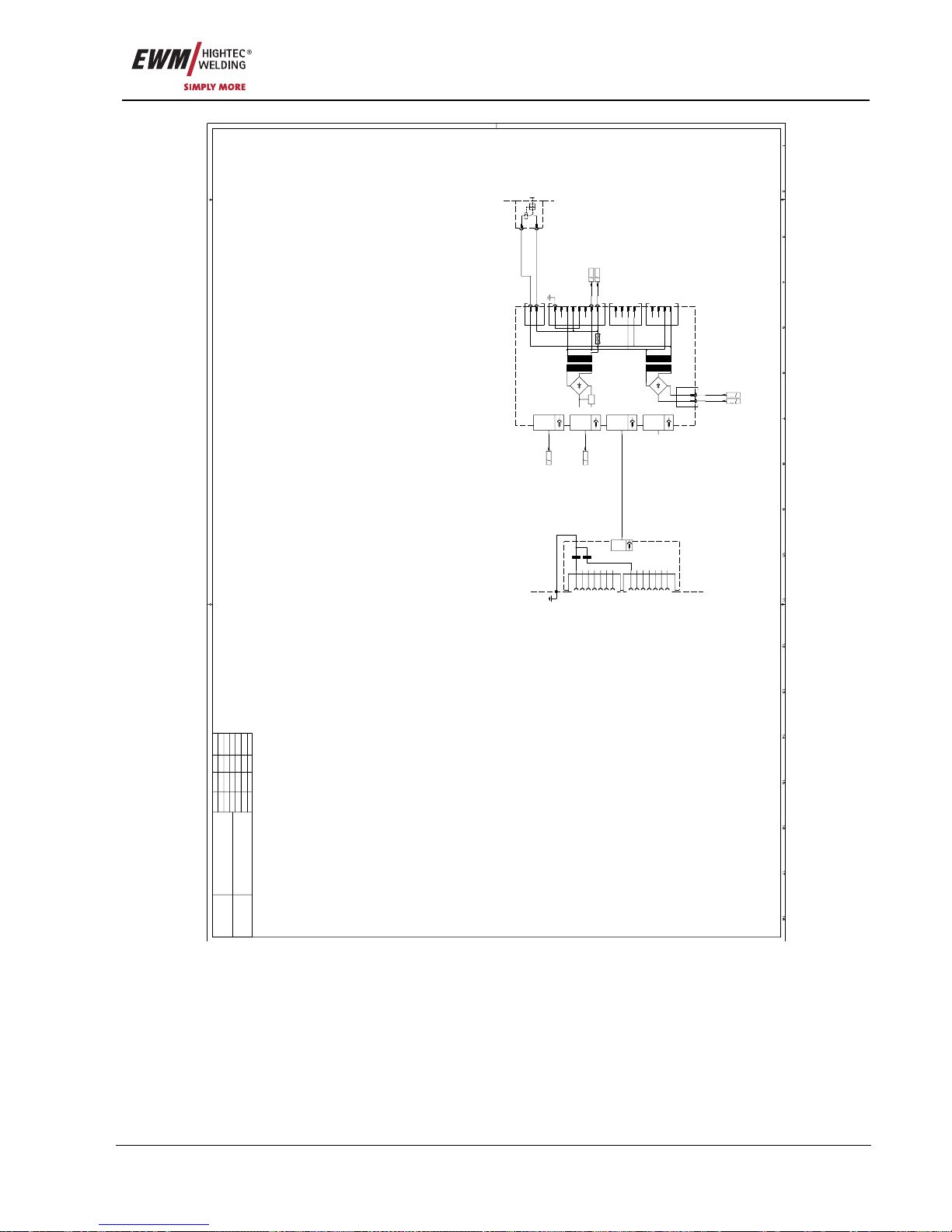
Circuit diagrams
PHOENIX 333 PROGRESS KG
Item No.: 099-005073-EWM01 95
X8/2
X8/1
15polig
D-Sub.
15polig
D-Sub.
15polig
D-Sub.
15polig
D-Sub.
X3/1
X3/2
X3/3
X3/4
X1/1
X1/2
X1/3
X1/4
X1/5
X1/6
X1/7
X1/8
T2
4AT
F1
T1
12V
W K - 6
A6-
X9/1
X9/2
X2/1
X2/2
X2/3
X2/4
X7
X6
X5
X4
X2
X3
X1
X9
X8
1
Absicherung2Absicherung
1
2
8
PE
1
42VAC
2
0VAC
A21B
21
15polig
D-SUB
Stecker X3
Schirm
0V
RS+12V
TXD
RXD
RSGND
42V
X1/7
X1/6
X1/5
X1/4
X1/3
X1/2
X1/1
Schirm
0V
RS+12V
RSGND
42V
X2/7
X2/6
X2/5
X2/4
X2/3
X2/2
X2/1
RXD
TXD
VP5/2D
2x2n2F
A7-
I 132
F
91
1
PE
1
Fühlerspannung
2
Fühlerspannung
G 101
H 101
1
2
4A
F1-
Datum: Name:
gezeichnet:
geprüft:
Freigabe:
10.10.2007 NIEDENTHAL
Blatt: /3
This drawing is protected by copyright.
It may not be reproduced or utilised in any way
or communicated or forwarded to third parties
without our express permission!
3
PHOENIX 333 PROGRESS
5034-00
Zeichnungsnummer:
WIG-GERAET, 3X400V FAHRBAR
Änderung-
Änderung-
Änderung-
Änderung-
Figure 11-3
Page 96
Appendix A
Declaration of Conformity
96 Item No.: 099-005073-EWM01
12 Appendix A
12.1 Declaration of Conformity
Originaldokument
liegt jedem Gerät bei!
Original document
is enclosed with each machine!
Document original
est joint à toute machine!
EG - Konformitätserklärung
EC – Declaration of Conformity
Déclaration de Conformité CE
Name des Herstellers:
Name of manufacturer:
Nom du fabricant:
EWM HIGHTEC WELDING GmbH
(nachfolgend EWM genannt)
(In the following called EWM)
(nommé par la suite EWM)
Anschrift des Herstellers:
Address of manufacturer:
Adresse du fabricant:
Dr.- Günter - Henle - Straße 8
D - 56271 Mündersbach – Germany
[email protected]
Hiermit erklären wir, daß das bezeichnete Gerät in seiner Konzeption und Bauart sowie in der von uns in Verkehr
gebrachten Ausführung den grundlegenden Sicherheits-anforderungen der
unten genannten EG- Richtlinien entspricht. Im Falle von unbefugten Veränderungen, unsachgemäßen Reparaturen
Nichteinhaltung der Fristen zur Wiederholungsprüfung und / oder unerlaubten
Umbauten, die nicht ausdrücklich von
EWM autorisiert sind, verliert diese
Erklärung ihre Gültigkeit.
We hereby declare that the machine below
conforms to the basic safety requirements
of the EC Directives cited both in its design
and construction, and in the version released by us. This declaration shall become null and void in the event of unauthorised modifications, improperly conducted repairs, non-observance of the
deadlines for the repetition test and/or nonpermitted conversion work not specifically
authorised by EWM.
Par la présente, nous déclarons que le
poste, dans sa conception et sa construction, ainsi que dans le modèle mis sur le
marché par nos services ci-dessous, correspondent aux directives fondamentales
de sécurité énoncées par l´CE et mentionnées ci-dessous. En cas de changements
non autorisés, de réparations inadéquates,
de non-respect des délais de contrôle en
exploitation et/ou de modifications prohibées n’ayant pas été autorisés expressément par EWM, cette déclaration devient
caduque.
Gerätebezeichnung:
Description of the machine:
Déscription de la machine:
Gerätetyp:
Type of machine:
Type de machine:
Artikelnummer EWM:
Article number:
Numéro d´article
Seriennummer:
Serial number:
Numéro de série:
Optionen:
Options:
Options:
keine
none
aucune
Zutreffende EG - Richtlinien:
Applicable EU - guidelines:
Directives de la CE applicables:
EG - Niederspannungsrichtlinie (2006/95/EG)
EC – Low Voltage Directive (2006/95/EG)
Directive CE pour basses tensions (2006/95/EG)
EG- EMV- Richtlinie (2004/108/EG)
EC – EMC Directive (2004/108/ EG)
Directive CE EMV (2004/108/EG)
Angewandte harmonisierte Normen:
Used co-ordinated norms:
Normes harmonisées appliquées:
EN 60974 / IEC 60974 / VDE 0544
EN 50199 / VDE 0544 part 206
GOST-R
Hersteller - Unterschrift:
Manufacturer's signature:
Signature du fabricant:
Michael Szczesny , Geschäftsführer
managing director
gérant
01.2007
Page 97
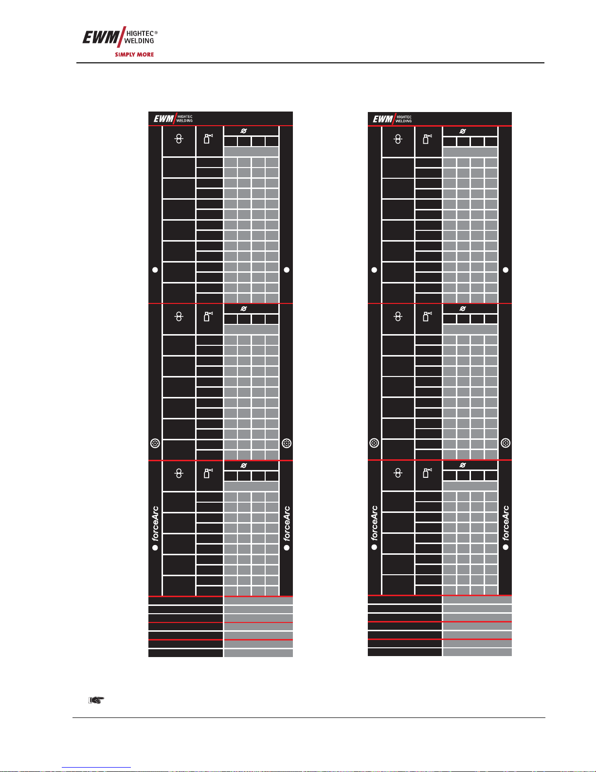
Appendix B
JOB-List
Item No.: 099-005073-EWM01 97
13 Appendix B
13.1 JOB-List
CrNi
CrNi
Ar98/2
Ar82/18
Ar82/18
Ar91...99
Ar80...90
Ar95/5
Ar82/18
Ar100
Ar98/2
CuAl
Ar100
Ar98/2
Ar91...99
Ar98/2
Ar100
Ar98/2
Ar100
Ar98/2
Ar100
Ar98/2
Ar92/8
Ar92/8
Ar92/8
AlMg
AlMg
Ar100
Ar/He
AlSi
AlSi
Ar100
Ar/He
Al99
Al99
GMAW Manuell <8m / min
SP3
SP2
SP1
GMAW Manuell >8m / min
WIG / TIG
MMA / E-Hand
Ar100
Ar/He
Wire
Wire
Wire
%
Gas
%
Gas
%
Gas
0,8
0,8
0,8
1
85
13
97
157
161
25
109
X
37
121
X
49
133
X
61
145
X
73
248
247
246
245
250
249
251
1,0
1,0
1,0
2
86
14
98
158
162
26
110
170
38
122
X
50
134
X
62
146
X
74
1,2
1,2
1,2
3
87
15
99
159
163
27
111
171
39
123
183
51
135
195
63
147
207
75
1,6
Job-Nr.
JOB-LIST
1,6
1,6
Job-Nr.
Job-Nr.
4
88
16
100
160
164
28
112
172
40
124
184
52
136
196
64
148
208
76
Material
Material
Material
5
17
29
41
125
53
137
65
149
77
6
18
30
42
126
54
138
66
150
78
7
19
31
43
127
55
139
67
151
79
8
20
32
44
128
56
140
68
152
80
SG2/3
G3/4 Si1
CuSi
Löten /
Brazing
SG2/3
G3/4 Si1
Metal
SG2/3
G3/4 Si1
Rutil / Basic
CrNi
Metal
CrNi
Rutil / Basic
CrNiMn
Metal
CrNiMn
Rutil / Basic
CO 100
2
09/07
SG2/3
G3/4 Si1
Massivdraht / Solid Wire
Fülldraht / Flux-Cored Wire
Massivdraht / Solid Wire
Fülldraht / Flux-Cored Wire
CrNi
CrNi
Ar91 - 99
Ar/He
Ar80 - 90
Ar80 - 90
Ar91 - 99
Ar80 - 90
Ar80 - 90
Ar91 - 99
Ar91 - 99
Ar98/2
Ar92/8
Ar100
Ar91 - 99
Ar100
Ar100
AlMg
AlSi
Al99
GMAW Manuell <8m / min
SP3
SP2
SP1
GMAW Manuell >8m / min
WIG / TIG
MMA / E-Hand
Wire
Wire
Wire
%
Gas
%
Gas
%
Gas
0,8
0,8
0,8
235
240
227
X
231
210
X
219
X
223
206
X
1,0
1,0
1,0
237
242
228
251
232
211
X
220
X
224
207
X
1,2
1,2
1,2
238
243
229
252
233
212
247
221
249
225
208
245
1,6
Job-Nr.
JOB-LIST
1,6
1,6
Job-Nr.
Job-Nr.
239
244
230
253
234
213
248
222
250
226
209
246
Material
Material
Material
SG2/3
G3/4 Si1
SG2/3
G3/4 Si1
Metal
SG2/3
G3/4 Si1
Rutil / Basic
CrNi
Metal
CrNi
Rutil / Basic
CrNiMn
Metal
CrNiMn
Rutil / Basic
CO 100
2
SG2/3
G3/4 Si1
Massivdraht / Solid Wire
Fülldraht / Flux-Cored Wire
Massivdraht / Solid Wire
Fülldraht / Flux-Cored Wire
1
34
42
190
189
188
131
130
129
127
187
128
3
35
43
254
179
4
36
44
255
180
5
37
45
256
181
68910
CuSi
Löten /
Brazing
CuAl
Löten /
Brazing
Ar100
114
115
116 117
Ar100
122 123 124 125
Ar91 - 99
110 111 11 2 11 3
Ar91 - 99
118 119 120 1 21
AlMg
Ar100
Ar/He
74
75
76 77
78 79 80 81
AlSi
Ar100
Ar/He
Al99
Ar100
Ar/He
82908391849285
93
86948795889689
97
Ar98/2
Ar92/8
Task-oriented JOB list Actual JOB list
See "M3.70/M3.71 machine controls – special parameters" chapter, P12 special parameters
 Loading...