

EWM MT551W Series, MT301W Series, MT451W Series, MT551W, MT301W Operating Instructions Manual
...
Operating instructions
EN
welding torch
MT301W
MT451W
MT551W
MT301W...X
MT451W...X
MT551W...X
099-500058-EW501 Observe additional system documents! 04.08.2016
Register now
and benefit!
Jetzt Registrieren
und Profitieren!
www.ewm-group.com
*For details visit
www.ewm-group.com
*

General instructions
WARNING
Read the operating instructions!
The operating instructions provide an introduction to the safe use of the products.
• Read and observe the operating instructions for all system components, especially the
safety instructions and warning notices!
• Observe the accident prevention regulations and any regional regulations!
• The operating instructions must be kept at the site of operation.
• Safety and warning labels at the machine indicate any possible risks.
Keep these labels clean and legible at all times.
• The machine has been constructed to the state of the art and any regulations and
standards applicable. It may be operated, serviced and repaired by trained personnel only.
In the event of queries on installation, commissioning, operation or special conditions at the
installation site, or on usage, please contact your sales partner or our customer service
department on +49 2680 181-0.
A list of authorised sales partners can be found at www.ewm-group.com.
Liability relating to the operation of this equipment is restricted solely to the function of the
equipment. No other form of liability, regardless of type, shall be accepted. This exclusion of
liability shall be deemed accepted by the user on commissioning the equipment.
The manufacturer is unable to monitor whether or not these instructions or the conditions and
methods are observed during installation, operation, usage and maintenance of the equipment.
An incorrectly performed installation can result in material damage and injure persons as a
result. For this reason, we do not accept any responsibility or liability for losses, damages or
costs arising from incorrect installation, improper operation or incorrect usage and maintenance
or any actions connected to this in any way.
© EWM AG
Dr. Günter-Henle-Str. 8
D-56271 Mündersbach, Germany
The copyright to this document remains the property of the manufacturer.
Reprinting, including extracts, only permitted with written approval.
The content of this document has been prepared and reviewed with all reasonable care. The information
provided is subject to change, errors excepted.

Contents
Notes on the use of these operating instructions
099-500058-EW501
04.08.2016
3
1 Contents
1
Contents .................................................................................................................................................. 3
2 Safety instructions ................................................................................................................................. 5
2.1 Notes on the use of these operating instructions .......................................................................... 5
2.1.1 Explanation of icons ....................................................................................................... 6
2.2 General .......................................................................................................................................... 7
2.3 Transport ........................................................................................................................................ 9
2.4 Scope of delivery ........................................................................................................................... 9
2.4.1 Ambient conditions ......................................................................................................... 9
2.4.1.1 In operation ..................................................................................................... 9
2.4.1.2 Transport and storage ..................................................................................... 9
3 Intended use ......................................................................................................................................... 10
3.1 General ........................................................................................................................................ 10
3.2 Documents which also apply ....................................................................................................... 10
3.2.1 Warranty ....................................................................................................................... 10
3.2.2 Declaration of Conformity ............................................................................................. 10
3.2.3 Service documents (spare parts) ................................................................................. 10
4 Product description – quick reference .............................................................................................. 11
4.1 Product variants ........................................................................................................................... 11
4.2 Standard welding torch ................................................................................................................ 12
4.3 Function torch .............................................................................................................................. 13
4.3.1 Operating elements ...................................................................................................... 14
4.3.2 Operating elements for up/down welding torch ............................................................ 14
4.3.3 Operating elements 2 for up/down welding torch ......................................................... 15
4.3.4 Operating elements for PC1 welding torch .................................................................. 16
4.3.4.1 Welding data display ..................................................................................... 17
4.3.5 Operating elements for PC2 welding torch .................................................................. 18
4.3.5.1 Welding data display ..................................................................................... 19
4.3.6 Euro torch connector with control cable ....................................................................... 20
4.3.7 Euro torch connector without control cable .................................................................. 20
4.4 Fume extraction torch .................................................................................................................. 21
4.4.1 Fume extraction torch Euro torch connector ................................................................ 22
4.5 Equipment recommendations ...................................................................................................... 23
5 Design and function ............................................................................................................................. 24
5.1 General ........................................................................................................................................ 24
5.2 Welding torch cooling system ...................................................................................................... 25
5.2.1 Approved coolants overview ........................................................................................ 25
5.2.2 Maximal hose package length ...................................................................................... 25
5.3 Configure welding torch ............................................................................................................... 26
5.3.1 Turning the torch neck .................................................................................................. 27
5.3.2 Changing the torch neck .............................................................................................. 27
5.4 Adjusting the welding machine Euro torch connector .................................................................. 29
5.4.1 Preparation work on the euro torch connector to connect welding torches with
plastic liners .................................................................................................................. 29
5.4.2 Preparation work on the central connector to connect welding torches with spiral
guides ........................................................................................................................... 29
5.5 Assemble the wire guide .............................................................................................................. 29
5.5.1 Combined liner ............................................................................................................. 30
5.5.2 Guide spiral .................................................................................................................. 33
6 Maintenance, care and disposal ......................................................................................................... 36
6.1 Maintenance work, intervals ........................................................................................................ 36
6.1.1 Daily maintenance tasks .............................................................................................. 36
6.1.2 Monthly maintenance tasks .......................................................................................... 36
6.2 Maintenance work ........................................................................................................................ 36
6.3 Disposing of equipment ............................................................................................................... 37
6.3.1 Manufacturer's declaration to the end user .................................................................. 37

Contents
Notes on the use of these operating instructions
4
099-500058-EW501
04.08.2016
6.4 Meeting the requirements of RoHS .............................................................................................. 37
7 Rectifying faults.................................................................................................................................... 38
7.1 Checklist for rectifying faults ........................................................................................................ 38
7.2 Functional check PC1X – PC2X .................................................................................................. 40
7.3 Vent coolant circuit ....................................................................................................................... 41
8 Technical data....................................................................................................................................... 42
8.1 MT 301 / 451 / 551 ....................................................................................................................... 42
9 Replaceable parts ................................................................................................................................. 43
9.1 MT301W ....................................................................................................................................... 43
9.2 MT451W ....................................................................................................................................... 45
9.3 MT551W ....................................................................................................................................... 47
9.4 MT301W F ................................................................................................................................... 49
9.5 MT451W F ................................................................................................................................... 50
10Circuit diagrams ................................................................................................................................... 52
10.1 MT U/D ......................................................................................................................................... 52
10.2 MT U/DX....................................................................................................................................... 53
10.3 MT 2U/D ....................................................................................................................................... 54
10.4 MT 2U/DX .................................................................................................................................... 55
10.5 MT PC1 ........................................................................................................................................ 56
10.6 MT PC1X ...................................................................................................................................... 57
10.7 MT PC2 ........................................................................................................................................ 58
10.8 MT PC2X ...................................................................................................................................... 59
11Appendix A ............................................................................................................................................ 60
11.1 Overview of EWM branches......................................................................................................... 60

Safety instructions
Notes on the use of these operating instructions
099-500058-EW501
04.08.2016
5
2 Safety instructions
2.1 Notes on the use of these operating instructions
DANGER
Working or operating procedures which must be closely observed to prevent imminent
serious and even fatal injuries.
• Safety notes include the "DANGER" keyword in the heading with a general warning symbol.
• The hazard is also highlighted using a symbol on the edge of the page.
WARNING
Working or operating procedures which must be closely observed to prevent serious
and even fatal injuries.
• Safety notes include the "WARNING" keyword in the heading with a general warning
symbol.
• The hazard is also highlighted using a symbol in the page margin.
CAUTION
Working or operating procedures which must be closely observed to prevent possible
minor personal injury.
• The safety information includes the "CAUTION" keyword in its heading with a general
warning symbol.
• The risk is explained using a symbol on the edge of the page.
Special technical points which users must observe.
Instructions and lists detailing step-by-step actions for given situations can be recognised via bullet
points, e.g.:
• Insert the welding current lead socket into the relevant socket and lock.

Safety instructions
Notes on the use of these operating instructions
6
099-500058-EW501
04.08.2016
2.1.1 Explanation of icons
Symbol Description Symbol Description
Indicates technical aspects which the
user must observe.
Activate and release/tap/tip
l
0
Switch off machine
Release/do not activate
l
0
Switch on machine
Press and hold
switch
Wrong
Turn
Correct
Numerical value – adjustable
Menu entry
Signal light lights up in green
Navigating the menu
Signal light flashes green
Exit menu
Signal light lights up in red
4s
Time representation (e.g.: wait
4 s/activate)
Signal light flashes red
Interruption in the menu display (other
setting options possible)
Tool not required/do not use
Tool required/use

Safety instructions
General
099-500058-EW501
04.08.2016
7
2.2 General
WARNING
Risk of injury from electrical voltage!
Voltages can cause potentially fatal electric shocks and burns on contact. Even low
voltages can cause a shock and lead to accidents.
• Never touch live components such as welding current sockets or stick, tungsten or wire
electrodes!
• Always place torches and electrode holders on an insulated surface!
• Wear the full personal protective equipment (depending on the application)!
• The machine may only be opened by qualified personnel!
Fire hazard!
Due to the high temperatures, sparks, glowing parts and hot slag that occur during
welding, there is a risk of flames.
• Be watchful of potential sources of fire in the working area!
• Do not carry any easily inflammable objects, e.g. matches or lighters.
• Ensure suitable fire extinguishers are available in the working area!
• Thoroughly remove any residue of flammable materials from the workpiece prior to starting
to weld.
• Only further process workpieces after they have cooled down. Do not allow them to contact
any flammable materials!
Risk of injury due to radiation or heat!
Arc radiation results in injury to skin and eyes.
Contact with hot workpieces and sparks results in burns.
• Use welding shield or welding helmet with the appropriate safety level (depending on the
application)!
• Wear dry protective clothing (e.g. welding shield, gloves, etc.) according to the relevant
regulations in the country in question!
• Protect persons not involved in the work against arc beams and the risk of glare using
safety curtains!
Risk of accidents due to non-compliance with the safety instructions!
Non-compliance with the safety instructions can be fatal!
• Carefully read the safety instructions in this manual!
• Observe the accident prevention regulations and any regional regulations!
• Inform persons in the working area that they must comply with the regulations!

Safety instructions
General
8
099-500058-EW501
04.08.2016
CAUTION
Electromagnetic fields!
The power source may cause electrical or electromagnetic fields to be produced which
could affect the correct functioning of electronic equipment such as IT or CNC devices,
telecommunication lines, power cables, signal lines and pacemakers.
• Observe the maintenance instructions > see 6.1 chapter!
• Unwind welding leads completely!
• Shield devices or equipment sensitive to radiation accordingly!
• The correct functioning of pacemakers may be affected (obtain advice from a doctor if
necessary).
Noise exposure!
Noise exceeding 70 dBA can cause permanent hearing damage!
• Wear suitable ear protection!
• Persons located within the working area must wear suitable ear protection!
Trained personnel!
Commissioning is reserved for persons who have the relevant expertise of working with arc
welding machines.
This document is valid only in combination with the operating instructions for the product being
used!
• Read and observe the operating instructions for all system components, especially the safety
instructions!
Obligations of the operator!
The respective national directives and laws must be observed for operation of the machine!
• National implementation of the framework directive (89/391/EWG), as well as the associated
individual directives.
• In particular, directive (89/655/EWG), on the minimum regulations for safety and health
protection when staff members use equipment during work.
• The regulations regarding work safety and accident prevention for the respective country.
• Setting up and operating the machine according to IEC 60974-9.
• Check at regular intervals that users are working in a safety-conscious way.
• Regular checks of the machine according to IEC 60974-4.
The manufacturer's warranty becomes void if non-genuine parts are used!
• Only use system components and options (power sources, welding torches, electrode
holders, remote controls, spare parts and replacement parts, etc.) from our range of products!
• Only insert and lock accessory components into the relevant connection socket when the
machine is switched off.

Safety instructions
Transport
099-500058-EW501
04.08.2016
9
2.3 Transport
CAUTION
Risk of accidents due to supply lines!
During transport, attached supply lines (mains leads, control cables, etc.) can cause
risks, e.g. by causing connected machines to tip over and injure persons!
• Disconnect all supply lines before transport!
2.4 Scope of delivery
The delivery is checked and packaged carefully before dispatch, however it is not possible to exclude the
possibility of damage during transit.
Receiving inspection
• Check that the delivery is complete using the delivery note!
In the event of damage to the packaging
• Check the delivery for damage (visual inspection)!
In the event of complaints
If the delivery has been damaged during transport:
• Please contact the last haulier immediately!
• Keep the packaging (for possible checking by the haulier or for the return shipment).
Packaging for returns
If possible, please use the original packaging and the original packaging material. If you have any queries
on packaging and protection during transport, please contact your supplier.
2.4.1 Ambient conditions
Unusually high quantities of dust, acid, corrosive gases or substances may damage the
equipment.
• Avoid high volumes of smoke, vapour, oil vapour and grinding dust!
• Avoid ambient air containing salt (sea air)!
2.4.1.1 In operation
Temperature range of the ambient air:
• -10 °C to +40 °C
Relative air humidity:
• Up to 50% at 40 °C
• Up to 90% at 20 °C
2.4.1.2 Transport and storage
Storage in an enclosed space, temperature range of the ambient air:
• -25 °C to +55 °C
Relative air humidity
• Up to 90% at 20 °C

Intended use
General
10
099-500058-EW501
04.08.2016
3 Intended use
3.1 General
WARNING
Hazards due to improper usage!
The machine has been constructed to the state of the art and any regulations and
standards applicable for use in industry and trade. It may only be used for the welding
procedures indicated at the rating plate. Hazards may arise for persons, animals and
material objects if the equipment is not used correctly. No liability is accepted for any
damages arising from improper usage!
• The equipment must only be used in line with its designated purpose and by trained or
expert personnel!
• Do not improperly modify or convert the equipment!
Welding torch for arc welding machines for GMAW.
3.2 Documents which also apply
3.2.1 Warranty
For more information refer to the "Warranty registration" brochure supplied and our information
regarding warranty, maintenance and testing at www.ewm-group.com!
3.2.2 Declaration of Conformity
The labelled machine complies with the following EC directives in terms of its design and
construction:
• Low Voltage Directive (LVD) 2014/35/EC
• Electromagnetic Compatibility Directive (EMC) 2014/30/EC
• Restriction of Hazardous Substance (RoHS) 2011/65/EC
In case of unauthorised changes, improper repairs, non-compliance with specified deadlines for "Arc
Welding Equipment – Inspection and Testing during Operation", and/or prohibited modifications which
have not been explicitly authorised by EWM, this declaration shall be voided. An original document of the
specific declaration of conformity is included with every product.
3.2.3 Service documents (spare parts)
WARNING
Do not carry out any unauthorised repairs or modifications!
To avoid injury and equipment damage, the unit must only be repaired or modified by
specialist, skilled persons!
The warranty becomes null and void in the event of unauthorised interference.
• Appoint only skilled persons for repair work (trained service personnel)!
Spare parts can be obtained from the relevant authorised dealer.

Product description – quick reference
Product variants
099-500058-EW501
04.08.2016
11
4 Product description – quick reference
4.1 Product variants
Version Functions Performance class
W Water-cooled
You use the torch trigger to switch the welding process on and
off. Interchangeable contact tip holder.
MT301, MT451, MT551
S Short torch neck
MT301, MT451, MT551
L Extended torch neck
MT451, MT551
C Interchangeable torch neck
The welding torch can be equipped with a torch neck angled
at 45°, 36° and 22°. The torch neck can be turned to the
desired position.
MT301, MT451
F Fume extraction torch
The fume extraction torch features an extraction unit. The
extraction capacity can be infinitely adjusted using a slider.
MT301, MT451
U/D Up/down torch
The welding power (welding current/wire feed speed) or the
program number can be adjusted on the welding torch.
MT301, MT451, MT551
2U/D 2 up/down torch
The welding power (welding current/wire feed speed) and the
voltage correction or the JOB number and program number
can be adjusted on the welding torch.
MT301, MT451, MT551
PC1 POWERCONTROL1 welding torch
The welding power (welding current/wire feed speed) or the
program number can be adjusted on the welding torch. Values
and changes are shown on the welding torch display.
MT301, MT451, MT551
PC2 POWERCONTROL2 welding torch
The welding power (welding current/wire feed speed) and the
voltage correction or the JOB number and program number
can be adjusted on the welding torch. Values and changes
are shown on the welding torch display.
MT301, MT451, MT551
X X technology (Multimatrix)
Welding torch with X technology – MT function torch without
separate control cable
MT301, MT451, MT551
The extended functions for welding torches MT301W…X, MT451W…X and MT551W…X are only
available if the welding torches on EWM machines are connected to the following control:
M3.70-A Phoenix Expert
M3.71-A Phoenix Progress
M3.72-A Alpha Q Progress
M3.76-A Taurus Synergic S
M3.7X-A drive 4X HP
M3.7X-B drive 4X LP

Product description – quick reference
Standard welding torch
12
099-500058-EW501
04.08.2016
4.2 Standard welding torch
4
3
2 1
5
Figure 4-1
Item Symbol Description 0
1
Gas nozzle
2
Torch neck 45°
3
Torch trigger
4
Grip plate
5 Welding torch hose package

Product description – quick reference
Function torch
099-500058-EW501
04.08.2016
13
4.3 Function torch
4
5
6
3 2 1
Figure 4-2
Item Symbol Description 0
1
Gas nozzle
2
Torch neck 45°
3
Operating elements
4
Grip plate
5
Torch trigger
6 Welding torch hose package

Product description – quick reference
Function torch
14
099-500058-EW501
04.08.2016
4.3.1 Operating elements
Programm
Up /
Down
Programm
Up /
Down
Figure 4-3
• Switch the"Program or up/down mode“ changeover switch at the welding machine to the up/down or
program mode position (see chapter "Design and function").
The 'Program or up/down function' changeover switch may look different on your machine. Use
the operating instructions for your power source to operate the switch.
4.3.2 Operating elements for up/down welding torch
U/D
X
21 21
Figure 4-4
Item Symbol Description 0
1
"A -" button (Program mode)
Decrease program number
"A -" button (Up/Down mode)
Reduce welding performance (welding current/wire-feed speed)
2
"A +" button (Program mode)
Increase program number
"A +" button (Up/Down mode)
Increase welding performance (welding current/wire-feed speed)

Product description – quick reference
Function torch
099-500058-EW501
04.08.2016
15
4.3.3 Operating elements 2 for up/down welding torch
2U/D
X
4
4
3
3
2
2
1
1
Figure 4-5
Item Symbol Description 0
1
"A +" button (Program mode)
Increase program number
"A +" button (Up/Down mode)
Increase welding performance (welding current/wire-feed speed)
2
"A -" button (Program mode)
Decrease program number
"A -" button (Up/Down mode)
Reduce welding performance (welding current/wire-feed speed)
3
"B +" button (program mode)
Increase JOB number
"B +" button (up/down mode)
Welding voltage correction, increase value
4
"B -" button (program mode)
Decrease JOB number
"B -" button (up/down mode)
Welding voltage correction, decrease value

Product description – quick reference
Function torch
16
099-500058-EW501
04.08.2016
4.3.4 Operating elements for PC1 welding torch
A A
1
Pc 1
X
3 3
1 1
2 2
Figure 4-6
Item Symbol Description 0
1
Three-figure display
Display of welding parameters > see 4.3.4.1 chapter.
2
"A +" button (Program mode)
Increase program number
"A +" button (Up/Down mode)
Increase welding performance (welding current/wire-feed speed)
3
"A -" button (Program mode)
Decrease program number
"A -" button (Up/Down mode)
Reduce welding performance (welding current/wire-feed speed)

Product description – quick reference
Function torch
099-500058-EW501
04.08.2016
17
4.3.4.1 Welding data display
The signal lamps in the lower part of the torch display indicate the welding parameters currently selected.
The corresponding parameter value is shown on the three-digit display.
After the welding machine is switched on, the active JOB number is shown on the display for approx. 3
seconds. The display then switches to the setpoint value for the welding current or wire speed.
In up/down mode, the corresponding parameter value is shown on the display for parameter changes. If
this parameter is not changed for approx. 5 seconds, the display switches back to the values specified by
the machine control.
A
32
1
Figure 4-7
Item Symbol Description 0
1
Three-figure display
Display of welding parameters > see 4.3.4.1 chapter.
2 A Welding current display signal lamp
3
Wire speed display signal lamp
Example displays for welding parameters in the welding data display
Welding parameters Display
Welding current
A
Wire speed
A
Programs
A

Product description – quick reference
Function torch
18
099-500058-EW501
04.08.2016
4.3.5 Operating elements for PC2 welding torch
A
V Job
A
V Job
PC2
X
4 4
1 1
5 5
3 3
2 2
Figure 4-8
Item Symbol Description 0
1
Three-figure display
Display of welding parameters > see 4.3.4.1 chapter.
2
"B +" button (program mode)
Increase JOB number
"B +" button (up/down mode)
Welding voltage correction, increase value
3
"A +" button (Program mode)
Increase program number
"A +" button (Up/Down mode)
Increase welding performance (welding current/wire-feed speed)
4
"A -" button (Program mode)
Decrease program number
"A -" button (Up/Down mode)
Reduce welding performance (welding current/wire-feed speed)
5
"B -" button (program mode)
Decrease JOB number
"B -" button (up/down mode)
Welding voltage correction, decrease value

Product description – quick reference
Function torch
099-500058-EW501
04.08.2016
19
4.3.5.1 Welding data display
The signal lamps in the lower part of the torch display indicate the welding parameters currently selected.
The corresponding parameter value is shown on the three-digit display.
After the welding machine is switched on, the active JOB number is shown on the display for approx. 3
seconds. The display then switches to the setpoint value for the welding current or wire speed.
In up/down mode, the corresponding parameter value is shown on the display for parameter changes. If
this parameter is not changed for approx. 5 seconds, the display switches back to the values specified by
the machine control.
V
A
JOB
432
1
5
Figure 4-9
Item Symbol Description 0
1
Three-figure display
Display of welding parameters > see 4.3.5.1 chapter.
2 A Welding current display signal lamp
3
Wire speed display signal lamp
4 V Voltage correction display signal lamp
5 JOB JOB number display signal lamp
Example displays for welding parameters in the welding data display
Welding parameters Display
Welding current
Wire speed
Voltage correction
Programs
JOB number
V
A
JOB
V
A
JOB
V
A
JOB
V
A
JOB
V
A
JOB

Product description – quick reference
Function torch
20
099-500058-EW501
04.08.2016
4.3.6 Euro torch connector with control cable
3
4
5
1
2
Figure 4-10
Item Symbol Description 0
1 Anti-kink spring
2
Euro central connection
3 Control cable plug
With function torches only
4 Quick connect coupling, blue (coolant supply)
5 Quick connect coupling, red (coolant return)
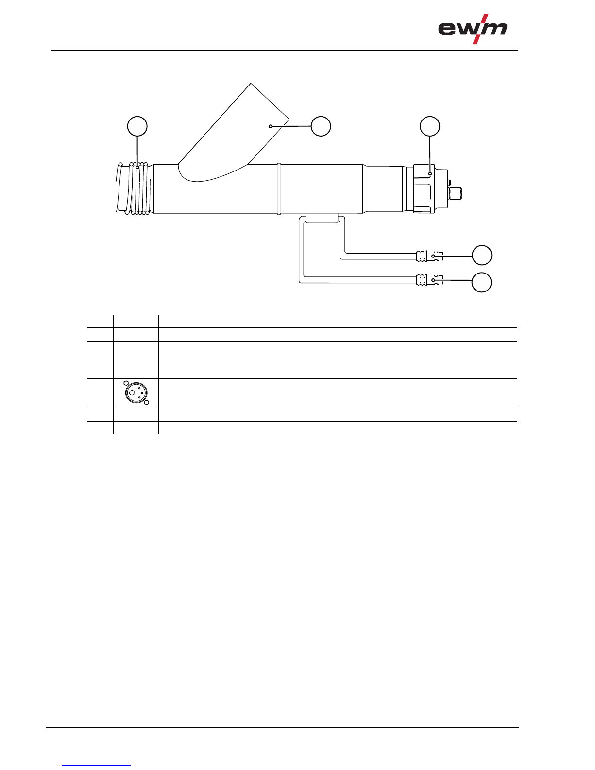
4.3.7 Euro torch connector without control cable
3
4
1
2
Figure 4-11
Item Symbol Description 0
1 Anti-kink spring
2
Euro central connection
Welding current, shielding gas and torch trigger included
3 Quick connect coupling, blue (coolant supply)
4 Quick connect coupling, red (coolant return)

Product description – quick reference
Fume extraction torch
099-500058-EW501
04.08.2016
21
4.4 Fume extraction torch
4
5
6
3
2
1
Figure 4-12
Item Symbol Description 0
1
Gas nozzle
2 Extraction unit
3 Slider, extraction capacity
4
Torch trigger
5
Grip plate
6 Extraction hose
Product description – quick reference
Fume extraction torch
22
099-500058-EW501
04.08.2016
4.4.1 Fume extraction torch Euro torch connector
21 3
4
5
Figure 4-13
Item Symbol Description 0
1 Anti-kink spring
2 Connection, extraction unit
Connect to extraction device or central extraction unit
= 42.5 mm
3
Euro central connection
4 Quick connect coupling, blue (coolant supply)
5 Quick connect coupling, red (coolant return)

Product description – quick reference
Equipment recommendations
099-500058-EW501
04.08.2016
23
4.5 Equipment recommendations
1
2
Material
Dia -
meter
wire
Contact tip
Dim ension
liner
Liner
Length
brass
spiral
Wire guide
equipment
Wire
feed
roller
0,8 1,5 x 4,0
1,0 1,5 x 4,0
1,2 2,0 x4,0
1,6 2,4 x 4,5
0,8 1,5 x 4,0
1,0 1,5 x 4,0
1,2 2,0 x4,0
1,6 2,3 x 4,7
0,8 1,5 x 4,0
1,0 1,5 x 4,0
1,2 2,0 x4,0
1,6 2,3 x 4,7
0,8 1,5 x 4,0
1,0 1,5 x 4,0
1,2 2,0 x4,0
1,6 2,3 x 4,7
0,8 1,5 x 4,0
1,0 1,5 x 4,0
1,2 2,0 x4,0
1,6 2,3 x 4,7
0,8 1,5 x 4,0
1,0 1,5 x 4,0
1,2 2,0 x4,0
1,6 2,3 x 4,7
0,8 1,5 x 4,0
1,0 1,5 x 4,0
1,2 2,0 x4,0
1,6 2,4 x 4,5
0,8 1,5 x 4,0
1,0 1,
5 x 4,0
1,2 2,0 x4,0
1,6 2,3 x 4,7
EWM
CuCrZr
Steel liner
insulated
Euro t orch
connector
V groove
capillary
tube
knurled V
groove
knurled V
groove
Euro t orch
connector
Euro t orch
connector
Euro t orch
connector
Euro t orch
connector
guide
tube
V groove
V groove
V groove
guide
tube
U groove
guide
tube
V groovePA combi l iner
EWM Alu
E-Cu
PA combi l iner 30 mm
EWM
CuCrZr
capillary
tube
Torch neck
Euro t orch
connector
Euro t orch
connector
guide
tube
200 mm
200 mm
EWM
CuCrZr
PA combi l iner
Copper
EWM
CuCrZr
PA combi l iner 200 mm
Stainless Steel
EWM
CuCrZr
GMAW Solid Wire
Un-alloyed
Stainless Steel
FCAW Flux Cored
Wire
Medium-alloyed
Hardfacing
Alumininium
Un-alloyed
guide
tube
EWM
CuCrZr
Steel liner
insulated
PA combi l iner 200 mm
guide
tube
EWM
CuCrZr
PA combi l iner 200 mm
1
2
2.
1.
1. capillary tube
2. guide tube
U-Nut
V groove
knurled V groove
Figure 4-14

Design and function
General
24
099-500058-EW501
04.08.2016
5 Design and function
5.1 General
WARNING
Risk of injury from electric shock!
Contact with live parts, e.g. welding current sockets, is potentially fatal!
• Follow safety instructions on the opening pages of the operating instructions.
• Commissioning may only be carried out by persons who have the relevant expertise of
working with arc welding machines!
• Connection and welding leads (e.g. electrode holder, welding torch, workpiece lead,
interfaces) may only be connected when the machine is switched off!
CAUTION
Risk of injury due to moving parts!
The wire feeders are equipped with moving parts, which can trap hands, hair, clothing
or tools and thus injure persons!
• Do not reach into rotating or moving parts or drive components!
• Keep casing covers or protective caps closed during operation!
Risk of injury due to welding wire escaping in an unpredictable manner!
Welding wire can be conveyed at very high speeds and, if conveyed incorrectly, may
escape in an uncontrolled manner and injure persons!
• Before mains connection, set up the complete wire guide system from the wire spool to the
welding torch!
• Remove the pressure rollers from the wire feeder if no welding torch is fitted!
• Check wire guide at regular intervals!
• Keep all casing covers or protective caps closed during operation!
Accessory components and the power source itself can be damaged by incorrect conn ection!
• Only insert and lock accessory components into the relevant connection socket when the
machine is switched off.
• Comprehensive descriptions can be found in the operating instructions for the relevant
accessory components.
• Accessory components are detected automatically after the power source is switched on.
Protective dust caps protect the connection sockets and therefore the machine against dirt and
damage.
• The protective dust cap must be fitted if there is no accessory component being operated on
that connection.
• The cap must be replaced if faulty or if lost!
Observe documentation of other system components when connecting!

Design and function
Welding torch cooling system
099-500058-EW501
04.08.2016
25
5.2 Welding torch cooling system
Insufficient frost protection in the welding torch coolant!
Depending on the ambient conditions, different liquids are used for cooling the welding
torch > see 5.2.1 chapter.
Coolants with frost protection (KF 37E or KF 23E) must be checked regularly to ensure that the
frost protection is adequate to prevent damage to the machine or the accessory components.
• The coolant must be checked for adequate frost protection with the TYP 1 frost protection
tester .
• Replace coolant as necessary if frost protection is inadequate!
Coolant mixtures!
Mixtures with other liquids or the use of unsuitable coolants result in material damage and
renders the manufacturer's warranty void!
• Only use the coolant described in this manual (overview of coolants).
• Do not mix different coolants.
• When changing the coolant, the entire volume of liquid must be changed.
Dispose of the coolant in accordance with local regulations and the material safety data sheets
(German waste code number: 70104).
May not be disposed of in household waste.
Prevent entry into sewers.
Absorb with liquid-binding material (sand, gravel, acid-binding agents, universal binding agents,
sawdust).
5.2.1 Approved coolants overview
Coolant Temperature range
KF 23E (Standard) -10 °C to +40 °C
KF 37E -20 °C to +10 °C
5.2.2 Maximal hose package length
Pump 3.5 bar Pump 4.5 bar
Machines with or without separate wire feeder 30 m 60 m
Compact machines with additional intermediate
drive (example. miniDrive)
20 m 30 m
Machines with separate wire feeder and additional
intermediate drive (example: miniDrive)
20 m 60 m
Data as a rule refer to the entire hose package length
including welding torch. The pump output is shown on the type plate (parameter: Pmax).
Pump 3.5 bar: Pmax = 0.35 MPa (3.5 bar)
Pump 4.5 bar: Pmax = 0.45 MPa (4.5 bar)
Design and function
Configure welding torch
26
099-500058-EW501
04.08.2016
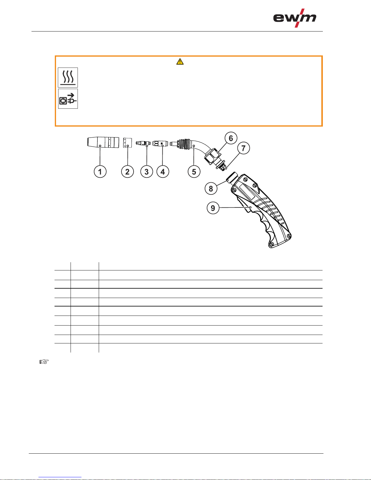
5.3 Configure welding torch
WARNING
Risk of burning or electric shock at the torch neck!
The torch neck and coolant (with water-cooled machines) become very hot during
welding.
You may get into contact with hot components or voltage when turning or changing the
torch neck.
• Switch off the power source and let the torch cool down!
• Wear dry and undamaged protective clothing (shoes with rubber soles/welder's gloves made
from leather without any studs or braces)!
Figure 5-1
Item Symbol Description 0
1
Gas nozzle
2 Gas distributor
3
Contact tip
4 Contact tip holder
5
Torch neck 45°
6
Crown nut
7
O-ring
8 Connection block
9
Grip plate
Damage to the machine due to worn O-rings!
Worn O-rings have a negative impact on the torch cooling. Insufficient cooling causes damage to
the torch.
• Check and if necessary replace all O-rings when converting the torch!

Design and function
Configure welding torch
099-500058-EW501
04.08.2016
27
5.3.1 Turning the torch neck
This function is only available with the "CG" and "CW" version!
• Unfasten the crown nut by several turns from the handle until the torch neck can move freely.
• Rotate the torch neck into the required position.
• Tighten the crown nut hand-tight until the torch neck can no longer be moved.
5.3.2 Changing the torch neck
WARNING
Risk of burning or electric shock at the torch neck!
The torch neck and coolant (with water-cooled machines) become very hot during
welding.
You may get into contact with hot components or voltage when turning or changing the
torch neck.
• Switch off the power source and let the torch cool down!
• Wear dry and undamaged protective clothing (shoes with rubber soles/welder's gloves made
from leather without any studs or braces)!
Welding torches can be fitted with a 45°, 36°, 22° and 0° angled torch neck as an option. To replace the
torch neck follow these instructions.
22°
0°
36°
45°45°
Figure 5-2

Design and function
Configure welding torch
28
099-500058-EW501
04.08.2016
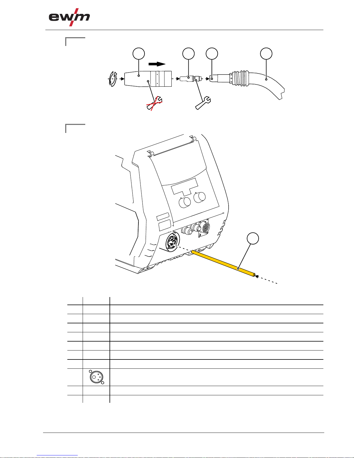
Switch off the welding machine before unfastening the torch neck!
1. 2.
3.
6
5
alt/old
1
2
3
4
neu/new
1
2
3
5
4.
1
2
3
5
7
4
Figure 5-3
Item Symbol Description 0
1
Grip plate
2
Crown nut
3
Torch neck 45°
4
Gas nozzle
5
Contact tip holder
6
Liner
7
Contact tip
Re-connect the welding torch after completing any maintenance work, use the 'gas test' function
to purge with shielding gas and vent > see 7.3 chapter.

Design and function
Adjusting the welding machine Euro torch connector
099-500058-EW501
04.08.2016
29
5.4 Adjusting the welding machine Euro torch connector
On delivery, the Euro torch connector is fitted with a capillary tube for welding torches with steel
liners!
5.4.1 Preparation work on the euro torch connector to connect welding torches with
plastic liners
• Push forward the capillary tube on the wire feed side in the direction of the euro torch connector and
remove at that point.
• Push on the guide pipe from the euro torch connector.
• Carefully insert the central plug for the welding torch, with the still oversized plastic core, into the euro
torch connector and screw together with crown nut.
• Use a special cutter or sharp knife to cut off the plastic core shortly before the wi re feed roller, making
sure not to pinch it.
• Unfasten and remove the central plug on the welding torch.
• Cleanly remove the burr from the separated end of the plastic core!
5.4.2 Preparation work on the central connector to connect welding torches with spiral
guides
• Check that the capillary tube is correctly positioned in relation to the central connector!
• Insert the central plug for the welding torch into the central connector and screw together with crown
nut.
5.5 Assemble the wire guide
Use the correct wire guide from spool to molten pool!
The wire guide has to be adjusted to the wire electrode type and diameter in order to achieve
good welding results!
• Equip the wire feeder according to wire electrode type and diameter!
• Refer to the manufacturer instructions for the right wire feed unit equipm ent. Refer to Annex 1
in these operating instructions for the right EWM machine equipment.
• Use a steel liner inside the torch hose package to guide hard, unalloyed wire electrodes
(steel)!
• Use a plastic liner inside the torch hose package to guide soft or alloyed wire electrodes!
> see 9 chapter

Design and function
Assemble the wire guide
30
099-500058-EW501
04.08.2016
5.5.1 Combined liner
A steel liner is installed at the connection side, whereas a combined liner is installed at the torch
side.
The distance between the plastic liner and drive rollers should be as short as possible.
Use only sharp, stable knives or special tongs for cutting to ensure that the plastic liner does not
become misshapen!
Always make sure the the hose package is straight when replacing the wire guide.
Figure 5-4
1.
1 2 3 4
Figure 5-5
2.
alt/old
9
8
6 7
5
Figure 5-6

Design and function
Assemble the wire guide
099-500058-EW501
04.08.2016
31
3.
alt/old
8 10 4
Figure 5-7
4.
Adjust steel liner > see 4.5 chapter.
neu/new
11
10 12
Figure 5-8
5.
neu/new
9
111110 4
100 - 120 mm
Figure 5-9
6.
1 2 3 4
Figure 5-10

Design and function
Assemble the wire guide
32
099-500058-EW501
04.08.2016
7.
neu/new
9
116 7
5
Figure 5-11
8.
9
11
13
Figure 5-12
Item Symbol Description 0
1
Gas nozzle
2
Contact tip
3
Contact tip holder
4
Torch neck 45°
5
Crown nut
6
O-ring
7
Collet
8 Combined liner
9
Euro central connection
10 Connecting sleeve
11 New combined liner
12 Liner sharpener
13
Guiding tube for welding torch Euro torch connector

Design and function
Assemble the wire guide
099-500058-EW501
04.08.2016
33
5.5.2 Guide spiral
Insert the grinded end towards the contact tip holder to ensure tight fit wit h the contact tip.
Always make sure the the hose package is straight when replacing the wire guide.
Figure 5-13
1.
1 2 3 4
Figure 5-14
2.
alt/old
8
765
Figure 5-15

Design and function
Assemble the wire guide
34
099-500058-EW501
04.08.2016
3.
neu/new
9
6
Figure 5-16
4.
neu/new
8
6 95
Figure 5-17
5.
9
3
3 9
Figure 5-18
Design and function
Assemble the wire guide
099-500058-EW501
04.08.2016
35
6.
1 2 3 4
Figure 5-19
7.
10
Figure 5-20
Item Symbol Description 0
1
Gas nozzle
2
Contact tip
3
Contact tip holder
4
Welding torch neck
5
Crown nut, welding torch central connection (euro)
6
Centring sleeve
7
old spiral guide
8
Euro central connection
9
new spiral guide
10 Capillary tube

Maintenance, care and disposal
Maintenance work, intervals
36
099-500058-EW501
04.08.2016
6 Maintenance, care and disposal
CAUTION
Electrical current!
The following work must always be carried out with the power source switched off.
Disconnect the welding torch from the connected device, before maintenance.
6.1 Maintenance work, intervals
6.1.1 Daily maintenance tasks
• Purge the wire guide from the direction of the Euro torch connector with oil- and condensate-free
compressed air or shielding gas.
• Purge the wire guide from the direction of the Euro torch connector with oil- and condensate-free
compressed air or shielding gas.
• Check that coolant connections are tight.
• Check that the welding torch, and where applicable the power source cooling, are functioning
correctly.
• Check the coolant level.
• Check torch, hose package and power connections for exterior damage and replace or have repaired
by specialist staff as necessary!
• Check the wearing parts in the torch.
• Check that all connections and wearing parts are hand-tight and tighten if necessary.
• Spray the gas nozzle with a splash protection agent.
6.1.2 Monthly maintenance tasks
• Check the coolant container for sludge deposits and check the coolant for cloudiness.
Clean the coolant container if contaminated, and change the coolant.
• If the coolant is dirty, rinse through the welding torch alternately several times with fresh coolant using
the coolant return and supply.
• Check the wire guide.
• Check and clean the welding torch. Deposits in the torch can cause sho rt circuits and have a negative
impact on the welding result, ultimately causing damage to the torch.
• Check that all screw and plug connections and replaceable parts are secured correctly, tighten if
necessary.
Re-connect the welding torch after completing any maintenance work, use the 'gas test' function
to purge with shielding gas and vent > see 7.3 chapter.
6.2 Maintenance work
Electric current!
Repairs may only be carried out by authorised specialist staff!
• Do not remove the torch from the hose package!
• Never clamp the torch body in a vice or similar, as this can cause the torch to be irreparably
destroyed!
• If damage occurs to the torch or to the hose package which cannot be corrected as part of the
maintenance work, the entire torch must be returned to the manufacturer

Maintenance, care and disposal
Disposing of equipment
099-500058-EW501
04.08.2016
37
6.3 Disposing of equipment
Proper disposal!
The machine contains valuable raw materials, which should be recycled, and electronic
components, which must be disposed of.
• Do not dispose of in household waste!
• Observe the local regulations regarding disposal!
6.3.1 Manufacturer's declaration to the end user
• According to European provisions (guideline 2012/19/EU of the European Parlia ment and the Council
of Juli, 4th 2021), used electric and electronic equipment may no longer be placed in unsorted
municipal waste. It must be collected separately. The symbol depicting a waste container on wheels
indicates that the equipment must be collected separately.
This machine is to be placed for disposal or recycling in the waste separation systems provided for
this purpose.
• According to German law (law governing the distribution, taking back and environmentally correct
disposal of electric and electronic equipment (ElektroG) from 16.03.2005), used machines are to be
placed in a collection system separate from unsorted municipal waste. The public waste management
utilities (communities) have created collection points at which used equipment from private
households can be disposed of free of charge.
• Information about giving back used equipment or about collections can be obtained from the
respective municipal administration office.
• EWM participates in an approved waste disposal and recycling system and is registered in the Used
Electrical Equipment Register (EAR) under number WEEE DE 57686922.
• In addition to this, returns are also possible throughout Europe via EWM sales partners.
6.4 Meeting the requirements of RoHS
We, EWM AG Mündersbach, hereby confirm that all products supplied by us which are affected by the
RoHS Directive, meet the requirements of the RoHS (Directive 2011/65/EU).

Rectifying faults
Checklist for rectifying faults
38
099-500058-EW501
04.08.2016
7 Rectifying faults
All products are subject to rigorous production checks and final checks. If, despite this, something fails to
work at any time, please check the product using the following flowchart. If none of the fault rectification
procedures described leads to the correct functioning of the product, please inform your authorised
dealer.
7.1 Checklist for rectifying faults
The correct machine equipment for the material and process gas in use is a fundamental
requirement for perfect operation!
Legend Symbol Description
Fault/Cause
Remedy
Welding torch overheated
Check coolant flow rate
Insufficient coolant flow
Check coolant level and refill if necessary
Eliminate kinks in conduit system (hose packages)
Completely unroll the hose package and the torch hose package
Vent coolant circuit > see 7.3 chapter
Loose welding current connections
Tighten power connections on the torch and/or on the workpiece
Screw contact tip holder and gas nozzle tightly into place correctly
Tighten contact tip correctly
Overload
Check and correct welding current setting
Use a more powerful welding torch
Functional error with the welding torch operating elements
Connection problems
Make control lead connections and check that they are fitted correctly.
Wire feed problems
Unsuitable or worn welding torch equipment
Adjust contact tip to wire diameter and -material and replace if necessary
Adjust wire guide to material in use, blow through and replace if necessary
Kinked hose packages
Extend and lay out the torch hose package
Incompatible parameter settings
Check settings and correct if necessary

Rectifying faults
Checklist for rectifying faults
099-500058-EW501
04.08.2016
39
Unstable arc
Unsuitable or worn welding torch equipment
Adjust contact tip to wire diameter and -material and replace if necessary
Adjust wire guide to material in use, blow through and replace if necessary
Incompatible parameter settings
Check settings and correct if necessary
Pore formation
Inadequate or missing gas shielding
Check shielding gas setting and replace shielding gas cylinder if necessary
Shield welding site with protective screens (draughts affect the welding result)
Unsuitable or worn welding torch equipment
Check size of gas nozzle and replace if necessary
Condensation (hydrogen) in the gas tube
Purge hose package with gas or replace
Splashes in the gas nozzle
Gas distributor out of order or missing

Rectifying faults
Functional check PC1X – PC2X
40
099-500058-EW501
04.08.2016
7.2 Functional check PC1X – PC2X
The welding torch shown is an example only. Depending on the type used, torches may vary.
Mode for checking the display and push-buttons at the welding torch. Pressing the push-buttons will
select the separate LEDs on the display one after the other. At the same time, individual bars will flash
and skip once the push-button is pressed again.
Applies for all PC1X / PC2X welding torches and in combination with the drive 4X wire feeder only.
1
l
0
l
0
V
A
JOB
3
EXIT
V
A
JOB
2
V
A
JOB
V
A
JOB
V
A
JOB
V
A
JOB
V
A
JOB
Figure 7-1

Rectifying faults
Vent coolant circuit
099-500058-EW501
04.08.2016
41
7.3 Vent coolant circuit
To vent the cooling system always use the blue coolant connection, which is located as deep as
possible inside the system (close to the coolant tank)!
maxmax
1
2
ca. 5s
3
4
7
6
5
KLICK
CLICK
KLICK
CLICK
092-007861-00000
blau / blue
l
0
l
0
l
0
Figure 7-2
Complete the following steps to vent the welding torch:
• Connect the welding torch to the cooling unit
• Switch on the welding machine
• Tao the torch trigger
Venting the welding torch starts and lasts for approx. 5 to 6 minutes.

Technical data
MT 301 / 451 / 551
42
099-500058-EW501
04.08.2016
8 Technical data
8.1 MT 301 / 451 / 551
Performance specifications and guarantee only in connection with original spare and
replacement parts!
Type MT301W
MT301WX
MT451W
MT451WX
MT551W
MT551WX
Welding torch polarity
Usually positive
Guide type
Manually operated
Voltage type
DC
Shielding gas
CO
2
or mixed gas M21 according to DIN EN 439
Duty cycle
100%
Maximum welding current, M21
300 A 450 A 550 A
Maximum welding current, pulse M21
260 A 350 A 500 A
Maximum welding current, CO2
350 A 500 A 650 A
Switching voltage microswitch
15 V
Switching current microswitch
10 mA
Required cooling capacity
min. 800 W
Torch input pressure for coolant
(min.–max.)
3 to 6 bar
Wire types
Standard round wires
Wire diameter
0.8 to 1.2 mm 0.8 to 1.6 mm 0.8 to 2.0 mm
Ambient temperature
-10 °C to +40 °C
Voltage measurement
113 V (peak value)
Protection rating for the machine
connections (EN 60529)
IP3X
Gas flow
10 to 25 l/min
Hose package length
3 m/4 m/5 m
Connection
Euro torch connector
Constructed to standard
IEC 60974-7

Replaceable parts
MT301W
099-500058-EW501
04.08.2016
43
9 Replaceable parts
The manufacturer's warranty becomes void if non-genuine parts are used!
• Only use system components and options (power sources, welding torches, electrode
holders, remote controls, spare parts and replacement parts, etc.) from our range of products!
• Only insert and lock accessory components into the relevant connection socket when the
machine is switched off.
9.1 MT301W
1
4
3
2
1.3
1.2
2.2
3.1
1.6
Figure 9-1
Item. Order number Type Designation
1 094-013061-00001 GN TR 20 66mm D=13mm Gas nozzle
1 094-013062-00001 GN TR 20 66mm D=11mm
Gas nozzle
1 094-013063-00001 GN TR 20 66mm D=16mm
Gas nozzle
1.2 094-020136-00000 GN TR 20x4 68mm D=10,5mm Gas nozzle cylinder neck
1.3 094-013644-00000 GN FCW TR 20 58mm Gas nozzle, Innershield
1.6 094-020944-00000 GN TR 20, 75 mm, D=18 mm Spot welding nozzle
2 094-013071-00000 CT M6 CuCrZr, D=0,8 mm Contact tip
2 094-013072-00000 CT M6 CuCrZr, D=1,0 mm, L=28 mm
Contact tip
2 094-013122-00000 CT M6 CuCrZr, D=0,9 mm
Contact tip
2 094-013535-00000 CT CUCRZR M7X30MM D=0.8MM
Contact tip
2 094-013536-00000 CT CUCRZR M7X30MM D=0.9MM
Contact tip
2 094-013537-00000 CT CUCRZR M7X30MM D=1.0MM
Contact tip
2 094-013538-00000 CT CUCRZR M7X30MM D=1.2MM
Contact tip
2 094-013550-00000 CTAL E-CU M7X30MM D=0.8MM Contact tip, aluminium welding
2 094-013551-00000 CTAL E-CU M7X30MM D=0.9MM
Contact tip, aluminium welding
2 094-013552-00000 CTAL E-CU M7X30MM D=1.0MM
Contact tip, aluminium welding
2 094-013553-00000 CTAL E-CU M7X30MM D=1.2MM
Contact tip, aluminium welding
2 094-014317-00000 CT M6 CuCrZr D=1,2 mm
Contact tip
2 094-016101-00000 CT M6x28mm 0.8mm E-CU
Contact tip
2 094-016102-00000 CT M6x28mm 0.9mm E-CU
Contact tip
2 094-016103-00000 CT M6x28mm 1.0mm E-CU
Contact tip
2 094-016104-00000 CT M6x28mm 1.2mm E-CU
Contact tip
2 094-016105-00000 CTAL E-CU M6X28MM D=0.8MM
Contact tip, aluminium welding
2 094-016106-00000 CTAL E-CU M6X28MM D=0.9MM
Contact tip, aluminium welding
2 094-016107-00000 CTAL E-CU M6X28MM D=1.0MM
Contact tip, aluminium welding
2 094-016108-00000 CTAL E-CU M6X28MM D=1.2MM
Contact tip, aluminium welding
2.2 094-005403-00000 CT M6 x 25 mm, 0.6 mm, CuCrZr
Contact tip
2.2 094-020689-00000 CT M6 x 25 mm, 0.8 mm, CuCrZr
Contact tip
2.2 094-020690-00000 CT M6 x 25 mm, 1.0 mm, CuCrZr
Contact tip

Replaceable parts
MT301W
44
099-500058-EW501
04.08.2016
Item. Order number Type Designation
2.2 094-020691-00000 CT M6 x 25 mm, 0.6 mm, E-Cu
Contact tip
2.2 094-020692-00000 CT M6 x 25 mm, 0.8 mm, E-Cu
Contact tip
2.2 094-020693-00000 CT M6 x 25 mm, 0.9 mm, E-Cu
Contact tip
2.2 094-020694-00000 CT M6 x 25 mm, 1.0 mm, E-Cu
Contact tip
2.2 094-020695-00000 CT M6 x 25 mm, 0.6 mm, E-Cu (Alu)
Contact tip, aluminium welding
2.2 094-020696-00000 CT M6 x 25 mm, 0.8 mm, E-Cu (Alu)
Contact tip, aluminium welding
2.2 094-020697-00000 CT M6 x 25 mm, 0.9 mm, E-Cu (Alu)
Contact tip, aluminium welding
2.2 094-020698-00000 CT M6 x 25 mm, 1.0 mm, E-Cu (Alu)
Contact tip, aluminium welding
3 094-013069-00002 CTH CUCRZR M6 L=30.5MM
Contackt tip holder
3 094-013070-00002 CTH CUCRZR M6 L=33.5MM
Contackt tip holder
3 094-013542-00002 CTH CUCRZR M7 L=34.5MM
Contackt tip holder
3 094-013541-00002 CTH CUCRZR M7 L=31.5MM
Contackt tip holder
3.1 094-020562-00000 CTH M6 CuCrZr 30.5mm
Contackt tip holder
4 094-013094-00002 GD MT221G / MT301W Gas diffuser
- 094-016038-00001 TT SW5-SW12MM Torch key

Replaceable parts
MT451W
099-500058-EW501
04.08.2016
45
9.2 MT451W
4
3
2
1
1.3
1.1
2.1
6
1.5
5
1.4
Figure 9-2
Item Order number Type Description
1 094-013105-00001 GN TR 22 71mm D=13mm Gas nozzle
1 094-013106-00001 GN TR 22 71mm D=15mm Gas nozzle
1 094-013107-00001 GN TR 22 71mm D=18mm Gas nozzle
1 094-019821-00001 GN TR 22 65mm D=15mm Gas nozzle, short
1 094-019822-00001 GN TR 22 65mm D=18mm Gas nozzle, short
1.1 094-019853-00001 GN NG TR22X4 71mm D=13mm Highly conical gas nozzle, narrow
gap welding
1.3 094-019554-00000 GN FCW TR 22x4 59.5MM Gas nozzle, Innershield
1.4 094-019626-00000 GN NG M12 73mm Gas nozzle, narrow gap welding
1.5 094-019623-00000 GNC TR22x4 Gas nozzle body
1.6 094-020945-00000 GN TR 22, 80 mm, D=20 mm Spot welding nozzle
2 094-007238-00000 CT E-CU M8X30MM D=1.2MM Contact tip
2 094-013113-00000 CT M8 CuCrZr 30mm, 1.2mm Contact tip
2 094-013129-00000 CT CUCRZR M8X30MM D=0.9MM Contact tip
2 094-013528-00000 CT CUCRZR M9X35MM D=0.8MM Contact tip
2 094-013529-00000 CT CUCRZR M9X35MM D=0.9MM Contact tip
2 094-013530-00000 CT M9 CuCrZr 1.0mm Contact tip
2 094-013531-00000 CT CUCRZR M9X35MM D=1.2MM Contact tip
2 094-013532-00000 CT CUCRZR M9X35MM D=1.4MM Contact tip
2 094-013533-00000 CT CUCRZR M9X35MM D=1.6MM Contact tip
2 094-013543-00000 CTAL E-CU M9X35MM D=0.8MM Contact tip, aluminium welding
2 094-013544-00000 CTAL E-CU M9X35MM D=0.9MM Contact tip, aluminium welding
2 094-013545-00000 CTAL E-CU M9X35MM D=1.0MM Contact tip, aluminium welding
2 094-013546-00000 CTAL E-CU M9X35MM D=1.2MM Contact tip, aluminium welding
2 094-013547-00000 CTAL E-CU M9X35MM D=1.4MM Contact tip, aluminium welding
2 094-013548-00000 CTAL E-CU M9X35MM D=1.6MM Contact tip, aluminium welding
2 094-014024-00000 CT CUCRZR M8X30MM D=0.8MM Contact tip
2 094-014191-00000 CT CUCRZR M8X30MM D=1.4MM Contact tip
2 094-014192-00000 CT CUCRZR M8X30MM D=1.6MM Contact tip
2 094-014222-00000 CT CUCRZR M8X30MM D=1.0MM Contact tip
2 094-016109-00000 CT E-CU M8X30MM D=0.8MM Contact tip
2 094-016110-00000 CT E-CU M8X30MM D=0.9MM Contact tip
2 094-016111-00000 CT E-CU M8X30MM D=1.0MM Contact tip

Replaceable parts
MT451W
46
099-500058-EW501
04.08.2016
Item Order number Type Description
2 094-016112-00000 CT E-CU M8X30MM D=1.4MM Contact tip
2 094-016113-00000 CT E-CU M8X30MM D=1.6MM Contact tip
2 094-016115-00000 CTAL E-CU M8X30MM D=0.8MM Contact tip, aluminium welding
2 094-016116-00000 CTAL E-CU M8X30MM D=0.9MM Contact tip, aluminium welding
2 094-016117-00000 CTAL E-CU M8X30MM D=1.0MM Contact tip, aluminium welding
2 094-016118-00000 CTAL E-CU M8X30MM D=1.2MM Contact tip, aluminium welding
2 094-016119-00000 CTAL E-CU M8X30MM D=1.4MM Contact tip, aluminium welding
2 094-016120-00000 CTAL E-CU M8X30MM D=1.6MM Contact tip, aluminium welding
2.1 094-019616-00000 CT M9 x 100 mm; Ø 1,0 mm CuCrZr Contact tip, narrow gap welding
2.1 094-019617-00000 CT M9 x 100 mm; Ø 1,2 mm CuCrZr Contact tip, narrow gap welding
2.1 094-019618-00000 CT M9 x 100 mm; Ø 1,6 mm CuCrZr Contact tip, narrow gap welding
2.1 094-020019-00000 CT M9 x 100 mm; Ø 1,4 mm CuCrZr Contact tip, narrow gap welding
2.1 094-021189-00000 CT M9 x 100 mm; Ø 0,8 mm CuCrZr Contact tip, narrow gap welding
3 094-013109-00002 CTH CUCRZR M8 L=34.1MM Contact tip holder
3 094-013110-00002 CTH CUCRZR M8 L=37.1MM Contact tip holder
3 094-013539-00002 CTH M9 CuCrZr 34.5mm Contact tip holder
3 094-013540-00002 CTH M9 CuCrZr 37.5mm Contact tip holder
4 094-013096-00003 GD MT301/451 Gas diffuser
5 094-019625-00000 IT ES M22X1,5 M12X1 Insulation part
6 094-019627-00000 ZH GDE ID=5MM AD=10MM L=15MM Centring sleeve
- 094-016038-00001 TT SW5-SW12MM Torch key

Replaceable parts
MT551W
099-500058-EW501
04.08.2016
47
9.3 MT551W
1.5
5
1.4
2.1
6
1.1
1
3
4
2
Figure 9-3
Item Order number Type Description
1 094-014177-00001 GN TR 23 63mm D=15mm Gas nozzle
1 094-014178-00001 GN TR 23 66mm D=15mm Gas nozzle
1 094-014179-00001 GN TR 23 63mm D=17mm Gas nozzle
1 094-014180-00001 GN TR 23 66mm D=17mm Gas nozzle
1 094-014181-00001 GN TR 23 63mm D=19mm Gas nozzle
1 094-014182-00001 GN TR 23 66mm D=19mm Gas nozzle
1.1 094-019702-00000 GN NG TR23X4 63mm D=13mm Highly conical gas nozzle, narrow
gap welding
1.4 094-019626-00000 GN NG M12 73mm Gas nozzle, narrow gap welding
1.5 094-019624-00000 GNC TR23x4 Gas nozzle body
2 094-007238-00000 CT E-CU M8X30MM D=1.2MM Contact tip
2 094-013113-00000 CT M8 CuCrZr 30mm, 1.2mm Contact tip
2 094-013129-00000 CT CUCRZR M8X30MM D=0.9MM Contact tip
2 094-013528-00000 CT CUCRZR M9X35MM D=0.8MM Contact tip
2 094-013529-00000 CT CUCRZR M9X35MM D=0.9MM Contact tip
2 094-013530-00000 CT M9 CuCrZr 1.0mm Contact tip
2 094-013531-00000 CT CUCRZR M9X35MM D=1.2MM Contact tip
2 094-013532-00000 CT CUCRZR M9X35MM D=1.4MM Contact tip
2 094-013533-00000 CT CUCRZR M9X35MM D=1.6MM Contact tip
2 094-013534-00000 CT CUCRZR M9X35MM D=2.0MM Contact tip
2 094-013543-00000 CTAL E-CU M9X35MM D=0.8MM Contact tip, aluminium welding
2 094-013544-00000 CTAL E-CU M9X35MM D=0.9MM Contact tip, aluminium welding
2 094-013545-00000 CTAL E-CU M9X35MM D=1.0MM Contact tip, aluminium welding
2 094-013546-00000 CTAL E-CU M9X35MM D=1.2MM Contact tip, aluminium welding
2 094-013547-00000 CTAL E-CU M9X35MM D=1.4MM Contact tip, aluminium welding
2 094-013548-00000 CTAL E-CU M9X35MM D=1.6MM Contact tip, aluminium welding
2 094-013549-00000 CTAL E-CU M9X35MM D=2.0MM Contact tip, aluminium welding
2 094-014024-00000 CT CUCRZR M8X30MM D=0.8MM Contact tip
2 094-014191-00000 CT CUCRZR M8X30MM D=1.4MM Contact tip
2 094-014192-00000 CT CUCRZR M8X30MM D=1.6MM Contact tip
2 094-014193-00000 CT CUCRZR M8X30MM D=2.0MM Contact tip
2 094-014222-00000 CT CUCRZR M8X30MM D=1.0MM Contact tip
2 094-016109-00000 CT E-CU M8X30MM D=0.8MM Contact tip
2 094-016110-00000 CT E-CU M8X30MM D=0.9MM Contact tip
2 094-016111-00000 CT E-CU M8X30MM D=1.0MM Contact tip

Replaceable parts
MT551W
48
099-500058-EW501
04.08.2016
Item Order number Type Description
2 094-016112-00000 CT E-CU M8X30MM D=1.4MM Conta ct tip
2 094-016113-00000 CT E-CU M8X30MM D=1.6MM Conta ct tip
2 094-016114-00000 CT E-CU M8X30MM D=2.0MM Conta ct tip
2 094-016115-00000 CTAL E-CU M8X30MM D=0.8MM Contact tip, aluminium welding
2 094-016116-00000 CTAL E-CU M8X30MM D=0.9MM Contact tip, aluminium welding
2 094-016117-00000 CTAL E-CU M8X30MM D=1.0MM Contact tip, aluminium welding
2 094-016118-00000 CTAL E-CU M8X30MM D=1.2MM Contact tip, aluminium welding
2 094-016119-00000 CTAL E-CU M8X30MM D=1.4MM Contact tip, aluminium welding
2 094-016120-00000 CTAL E-CU M8X30MM D=1.6MM Contact tip, aluminium welding
2 094-016920-00000 CTAL E-CU M8X30MM D=2.0MM Contact tip, aluminium welding
2.1 094-019616-00000 CT M9 x 100 mm; Ø 1,0 mm CuCrZr Contact tip, narrow gap welding
2.1 094-019617-00000 CT M9 x 100 mm; Ø 1,2 mm CuCrZr Contact tip, narrow gap welding
2.1 094-019618-00000 CT M9 x 100 mm; Ø 1,6 mm CuCrZr Contact tip, narrow gap welding
2.1 094-020019-00000 CT M9 x 100 mm; Ø 1,4 mm CuCrZr Contact tip, narrow gap welding
2.1 094-021189-00000 CT M9 x 100 mm; Ø 0,8 mm CuCrZr Contact tip, narrow gap welding
3 094-013856-00003 CTH CUCRZR M9 L=35MM Contact tip holder
3 094-015489-00003 CTH M8 x 35 mm, CuCrZr Contact tip holder
3 094-016018-00003 CTH M8 x 37,5 mm, CuCrZr Contact tip holder
3 094-016425-00003 CTH CUCRZR M9 L=38MM Contact tip holder
4 094-013111-00001 GD D=20,2 mm; 25 mm Gas diffuser
5 094-019625-00000 IT ES M22X1,5 M12X1 Insulation part
6 094-019627-00000 ZH GDE ID=5MM AD=10MM L=15MM Centring sleeve
- 094-016038-00001 TT SW5-SW12MM Torch key

Replaceable parts
MT301W F
099-500058-EW501
04.08.2016
49
9.4 MT301W F
4
3
2
1
7
Figure 9-4
Item. Order number Type Designation
1 094-013061-00001 GN TR 20 66mm D=13mm
Gas nozzle
1 094-013062-00001 GN TR 20 66mm D=11mm
Gas nozzle
1 094-013063-00001 GN TR 20 66mm D=16mm
Gas nozzle
2 094-013071-00000 CT M6 CuCrZr, D=0,8 mm Contact tip
2 094-013072-00000 CT M6 CuCrZr, D=1,0 mm, L=28 mm
Contact tip
2 094-013122-00000 CT M6 CuCrZr, D=0,9 mm
Contact tip
2 094-013535-00000 CT CUCRZR M7X30MM D=0.8MM
Contact tip
2 094-013536-00000 CT CUCRZR M7X30MM D=0.9MM
Contact tip
2 094-013537-00000 CT CUCRZR M7X30MM D=1.0MM
Contact tip
2 094-013538-00000 CT CUCRZR M7X30MM D=1.2MM
Contact tip
2 094-013550-00000 CTAL E-CU M7X30MM D=0.8MM
Contact tip, aluminium welding
2 094-013551-00000 CTAL E-CU M7X30MM D=0.9MM
Contact tip, aluminium welding
2 094-013552-00000 CTAL E-CU M7X30MM D=1.0MM
Contact tip, aluminium welding
2 094-013553-00000 CTAL E-CU M7X30MM D=1.2MM
Contact tip, aluminium welding
2 094-014317-00000 CT M6 CuCrZr D=1,2 mm
Contact tip
2 094-016101-00000 CT M6x28mm 0.8mm E-CU
Contact tip
2 094-016102-00000 CT M6x28mm 0.9mm E-CU
Contact tip
2 094-016103-00000 CT M6x28mm 1.0mm E-CU
Contact tip
2 094-016104-00000 CT M6x28mm 1.2mm E-CU
Contact tip
2 094-016105-00000 CTAL E-CU M6X28MM D=0.8MM
Contact tip, aluminium welding
2 094-016106-00000 CTAL E-CU M6X28MM D=0.9MM
Contact tip, aluminium welding
2 094-016107-00000 CTAL E-CU M6X28MM D=1.0MM
Contact tip, aluminium welding
2 094-016108-00000 CTAL E-CU M6X28MM D=1.2MM Contact tip, aluminium welding
3 094-013069-00002 CTH CUCRZR M6 L=30.5MM Contact tip holder
3 094-013070-00002 CTH CUCRZR M6 L=33.5MM
Contact tip holder
3 094-013541-00002 CTH CUCRZR M7 L=31.5MM
Contact tip holder
4 094-013094-00002 GD MT221G / MT301W Gas diffuser
7 094-014998-00000 RAD MT221GF/MT301WF Extraction nozzle
- 094-016038-00001 TT SW5-SW12MM Torch key

Replaceable parts
MT451W F
50
099-500058-EW501
04.08.2016
9.5 MT451W F
4
3
2
1
7
Figure 9-5
Item Order number Type Description
1 094-013105-00001 GN TR 22 71mm D=13mm Gas nozzle
1 094-013106-00001 GN TR 22 71mm D=15mm Gas nozzle
1 094-013107-00001 GN TR 22 71mm D=18mm Gas nozzle
1 094-019821-00001 GN TR 22 65mm D=15mm Gas nozzle, short
1 094-019822-00001 GN TR 22 65mm D=18mm Gas nozzle, short
2 094-007238-00000 CT E-CU M8X30MM D=1.2MM Contact tip
2 094-013113-00000 CT M8 CuCrZr 30mm, 1.2mm Contact tip
2 094-013129-00000 CT CUCRZR M8X30MM D=0.9MM Contact tip
2 094-013528-00000 CT CUCRZR M9X35MM D=0.8MM Contact tip
2 094-013529-00000 CT CUCRZR M9X35MM D=0.9MM Contact tip
2 094-013530-00000 CT M9 CuCrZr 1.0mm Contact tip
2 094-013531-00000 CT CUCRZR M9X35MM D=1.2MM Contact tip
2 094-013532-00000 CT CUCRZR M9X35MM D=1.4MM Contact tip
2 094-013533-00000 CT CUCRZR M9X35MM D=1.6MM Contact tip
2 094-013543-00000 CTAL E-CU M9X35MM D=0.8MM Contact tip, aluminium welding
2 094-013544-00000 CTAL E-CU M9X35MM D=0.9MM Contact tip, aluminium welding
2 094-013545-00000 CTAL E-CU M9X35MM D=1.0MM Contact tip, aluminium welding
2 094-013546-00000 CTAL E-CU M9X35MM D=1.2MM Contact tip, aluminium welding
2 094-013547-00000 CTAL E-CU M9X35MM D=1.4MM Contact tip, aluminium welding
2 094-013548-00000 CTAL E-CU M9X35MM D=1.6MM Contact tip, aluminium welding
2 094-014024-00000 CT CUCRZR M8X30MM D=0.8MM Contact tip
2 094-014191-00000 CT CUCRZR M8X30MM D=1.4MM Contact tip
2 094-014192-00000 CT CUCRZR M8X30MM D=1.6MM Contact tip
2 094-014222-00000 CT CUCRZR M8X30MM D=1.0MM Contact tip
2 094-016109-00000 CT E-CU M8X30MM D=0.8MM Contact tip
2 094-016110-00000 CT E-CU M8X30MM D=0.9MM Contact tip
2 094-016111-00000 CT E-CU M8X30MM D=1.0MM Contact tip
2 094-016112-00000 CT E-CU M8X30MM D=1.4MM Contact tip
2 094-016113-00000 CT E-CU M8X30MM D=1.6MM Contact tip
2 094-016115-00000 CTAL E-CU M8X30MM D=0.8MM Contact tip, aluminium welding
2 094-016116-00000 CTAL E-CU M8X30MM D=0.9MM Contact tip, aluminium welding
2 094-016117-00000 CTAL E-CU M8X30MM D=1.0MM Contact tip, aluminium welding
2 094-016118-00000 CTAL E-CU M8X30MM D=1.2MM Contact tip, aluminium welding
2 094-016119-00000 CTAL E-CU M8X30MM D=1.4MM Contact tip, aluminium welding
2 094-016120-00000 CTAL E-CU M8X30MM D=1.6MM Contact tip, aluminium welding
3 094-013109-00002 CTH CUCRZR M8 L=34.1MM Contact tip holder
3 094-013110-00002 CTH CUCRZR M8 L=37.1MM Contact tip holder
3 094-013539-00002 CTH M9 CuCrZr 34.5mm Contact tip holder
3 094-013540-00002 CTH M9 CuCrZr 37.5mm Contact tip holder

Replaceable parts
MT451W F
099-500058-EW501
04.08.2016
51
Item Order number Type Description
4 094-013096-00003 GD MT301/451 Gas diffuser
7 094-014997-00000 RAD MT451 WF Extraction nozzle
- 094-016038-00001 TT SW5-SW12MM Torch key

Circuit diagrams
MT U/D
52
099-500058-EW501
04.08.2016
10 Circuit diagrams
The circuit diagrams are only intended for authorised service personnel!
10.1 MT U/D
Figure 10-1

Circuit diagrams
MT U/DX
099-500058-EW501
04.08.2016
53
10.2 MT U/DX
U/D
X
-
+
A3
A4
rt (+)
bl (-)
B
A2
bn
A
A1
sw
Lötpunkt
Lötpunkt
U / D X
A1-
Lötpunkte
Polarität/ polarity +
Polarität/ polarity -
blau/blue
Ausführung/ version:
braun/brown
rot/redweiss/white
Polarität beachten/ take notice of polarity
wassergekühlt/ watercooled gasgekühlt/ gascooled
BRT
Brenneranschluss-Draufsicht/ torch connector top view Brenner-Draufsicht/ torch top view
Datum:
gezeichnet:
geprüft von:
07.05.2014
NIEDENTHAL
Änderung-
Änderung-
Änderung-
Änderung-
Blatt: /
SANDMANN
4
1
07.05.2014
Name:
Bez. 3:
Bez. 1:
U/D X MULTIMATRIX G/W
Bez. 2:
SCHWEISSBRENNER MT-SERIE
Schutzvermerk ISO16016 beachten
Refer to protection notice ISO16016
Artikelnummer:
10701-0-A
095-010161-00000
Zeichnungsnr-Index-Version:
1
2345
6
789
10
11
12
Figure 10-2

Circuit diagrams
MT 2U/D
54
099-500058-EW501
04.08.2016
10.3 MT 2U/D
Figure 10-3

Circuit diagrams
MT 2U/DX
099-500058-EW501
04.08.2016
55
10.4 MT 2U/DX
2U/D
X
-
+
A3
A4
rt (+)
bl (-)
B
A2
bn
A
A1
sw
Lötpunkt
Lötpunkt
A1-
Lötpunkte
Polarität/ polarity +
Polarität/ polarity -
blau/blue
Ausführung/ version:
braun/brown
rot/redweiss/white
Polarität beachten/ take notice of polarity
wassergekühlt/ watercooled gasgekühlt/ gascooled
BRT
Brenneranschluss-Draufsicht/ torch connector top view
2 U / D X
Brenner-Draufsicht/ torch top view
Datum:
gezeichnet:
geprüft von:
07.05.2014
NIEDENTHAL
Änderung-
Änderung-
Änderung-
Änderung-
Blatt: /
SANDMANN
4
2
07.05.2014
Name:
Bez. 3:
Bez. 1:
2U/D X MULTIMATRIX G/W
Bez. 2:
SCHWEISSBRENNER MT-SERIE
Schutzvermerk ISO16016 beachten
Refer to protection notice ISO16016
Artikelnummer:
10701-0-A
095-010161-00000
Zeichnungsnr-Index-Version:
1
2345
6
789
10
11
12
Figure 10-4

Circuit diagrams
MT PC1
56
099-500058-EW501
04.08.2016
10.5 MT PC1
Figure 10-5
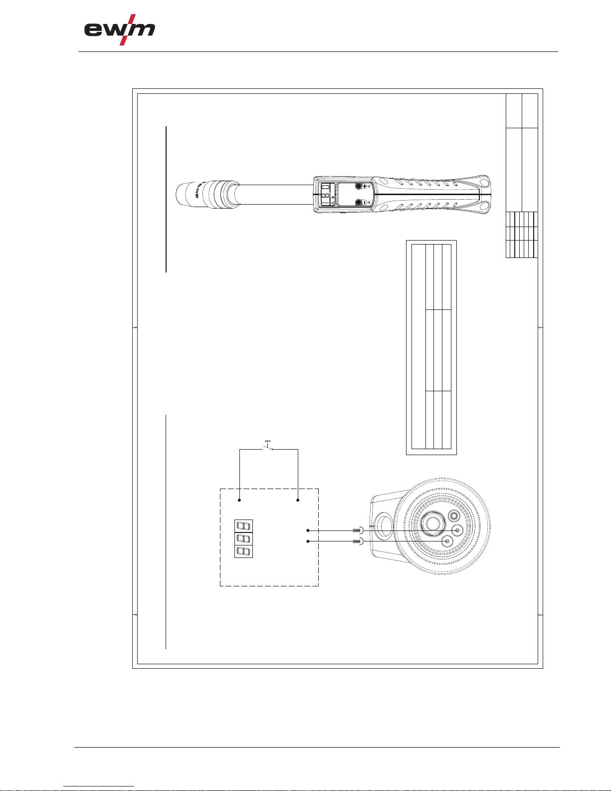
Circuit diagrams
MT PC1X
099-500058-EW501
04.08.2016
57
10.6 MT PC1X
X
PC1
-
+
A3
A4
rt (+)
bl (-)
B
A2
bn
A
A1
sw
Lötpunkt
Lötpunkt
P C 1 X
A1-
Lötpunkte
Polarität/ polarity +
Polarität/ polarity -
blau/blue
Ausführung/ version:
braun/brown
rot/redweiss/white
Polarität beachten/ take notice of polarity
wassergekühlt/ watercooled gasgekühlt/ gascooled
BRT
Brenneranschluss-Draufsicht/ torch connector top view
Brenner-Draufsicht/ torch top view
Datum:
gezeichnet:
geprüft von:
07.05.2014
NIEDENTHAL
Änderung-
Änderung-
Änderung-
Änderung-
Blatt: /
SANDMANN
4
3
07.05.2014
Name:
Bez. 3:
Bez. 1:
PC1 X MULTIMATRIX G/W
Bez. 2:
SCHWEISSBRENNER MT-SERIE
Schutzvermerk ISO16016 beachten
Refer to protection notice ISO16016
Artikelnummer:
10701-0-A
095-010161-00000
Zeichnungsnr-Index-Version:
1
2345
6
789
10
11
12
Figure 10-6

Circuit diagrams
MT PC2
58
099-500058-EW501
04.08.2016
10.7 MT PC2
Figure 10-7

Circuit diagrams
MT PC2X
099-500058-EW501
04.08.2016
59
10.8 MT PC2X
PC2
X
-
+
A3
A4
rt (+)
bl (-)
B
A2
bn
A
A1
sw
Lötpunkt
Lötpunkt
P C 2 X
A1-
Lötpunkte
Polarität/ polarity +
Polarität/ polarity -
blau/blue
Ausführung/ version:
braun/brown
rot/redweiss/white
Polarität beachten/ take notice of polarity
wassergekühlt/ watercooled gasgekühlt/ gascooled
BRT
Brenneranschluss-Draufsicht/ torch connector top view Brenner-Draufsicht/ torch top view
Datum:
gezeichnet:
geprüft von:
07.05.2014
NIEDENTHAL
Änderung-
Änderung-
Änderung-
Änderung-
Blatt: /
SANDMANN
4
4
07.05.2014
Name:
Bez. 3:
Bez. 1:
PC2 X MULTIMATRIX G/W
Bez. 2:
SCHWEISSBRENNER MT-SERIE
Schutzvermerk ISO16016 beachten
Refer to protection notice ISO16016
Artikelnummer:
10701-0-A
095-010161-00000
Zeichnungsnr-Index-Version:
1
2345
6
789
10
11
12
Figure 10-8

Appendix A
Overview of EWM branches
60
099-500058-EW501
04.08.2016
11 Appendix A
11.1 Overview of EWM branches
 Loading...