


Operating instructions
EN
Control
Synergic (M3.7X-M)
099-0M37XM-EW501
Observe additional system documents!
16.07.2018

WARNING
Read the operating instructions!
The operating instructions provide an introduction to the safe use of the products.
• Read and observe the operating instructions for all system components, especially the
safety instructions and warning notices!
• Observe the accident prevention regulations and any regional regulations!
• The operating instructions must be kept at the location where the machine is operated.
• Safety and warning labels on the machine indicate any possible risks.
Keep these labels clean and legible at all times.
• The machine has been constructed to state-of-the-art standards in line with any applicable
regulations and industrial standards. Only trained personnel may operate, service and
repair the machine.
• Technical changes due to further development in machine technology may lead to a
differing welding behaviour.
General instructions
In the event of queries on installation, commissioning, operation or special conditions at the
installation site, or on usage, please contact your sales partner or our customer service
department on +49 2680 181-0.
A list of authorised sales partners can be found at www.ewm-group.com/en/specialist-dealers.
Liability relating to the operation of this equipment is restricted solely to the function of the
equipment. No other form of liability, regardless of type, shall be accepted. This exclusion of
liability shall be deemed accepted by the user on commissioning the equipment.
The manufacturer is unable to monitor whether or not these instructions or the conditions and
methods are observed during installation, operation, usage and maintenance of the equipment.
An incorrectly performed installation can result in material damage and injure persons as a
result. For this reason, we do not accept any responsibility or liability for losses, damages or
costs arising from incorrect installation, improper operation or incorrect usage and maintenance
or any actions connected to this in any way.
© EWM AG
Dr. Günter-Henle-Strasse 8
56271 Mündersbach Germany
Tel.: +49 2680 181-0, Fax: -244
Email: info@ewm-group.com
www.ewm-group.com
The copyright to this document remains the property of the manufacturer.
Copying, including extracts, only permitted with written approval.
The content of this document has been prepared and reviewed with all reasonable care. The information
provided is subject to change; errors excepted.

Contents
Notes on the use of these operating instructions
099-0M37XM-EW501
16.07.2018
3
1 Contents
1 Contents .................................................................................................................................................. 3
2 For your safety ....................................................................................................................................... 5
2.1 Notes on the use of these operating instructions .......................................................................... 5
2.2 Explanation of icons ....................................................................................................................... 5
2.3 Part of the complete documentation .............................................................................................. 6
3 Intended use ........................................................................................................................................... 7
3.1 Use and operation solely with the following machines .................................................................. 7
3.2 Documents which also apply ......................................................................................................... 7
3.3 Software version ............................................................................................................................ 7
4 Machine control – Operating elements ................................................................................................ 8
4.1 Overview of control sections .......................................................................................................... 8
4.1.1 Control section A ............................................................................................................ 9
4.1.2 Control section B .......................................................................................................... 10
4.2 Welding data display .................................................................................................................... 11
4.3 Operating the machine control ..................................................................................................... 12
4.3.1 Main screen .................................................................................................................. 12
4.3.2 Welding power setting .................................................................................................. 12
4.3.3 Setting advanced welding parameters (Expert menu) ................................................. 12
4.3.4 Changing basic settings (machine configuration menu) .............................................. 12
4.3.5 Lock function ................................................................................................................ 12
5 Functional characteristics ................................................................................................................... 13
5.1.1 Shielding gas volume settings ...................................................................................... 13
5.1.2 Wire return .................................................................................................................... 14
5.2 MIG/MAG welding ........................................................................................................................ 15
5.2.1 Welding task selection .................................................................................................. 15
5.2.2 Expert menu (MIG/MAG) .............................................................................................. 17
5.2.3 Program sequence ....................................................................................................... 18
5.2.4 Operating modes (functional sequences) .................................................................... 18
5.2.5 Standard MIG/MAG torch ............................................................................................. 23
5.3 MMA welding ............................................................................................................................... 23
5.3.1 Welding task selection .................................................................................................. 23
5.3.2 Welding current setting ................................................................................................. 23
5.3.3 Arcforce ........................................................................................................................ 24
5.3.4 Hotstart ......................................................................................................................... 24
5.3.5 Antistick ........................................................................................................................ 24
5.4 Special parameters (advanced settings) ..................................................................................... 24
5.4.1 Selecting, changing and saving parameters ................................................................ 25
5.4.2 Reset to factory settings ............................................................................................... 26
5.5 Machine configuration menu ........................................................................................................ 27
5.5.1 Selecting, changing and saving parameters ................................................................ 27
5.1.1.1 Gas test ......................................................................................................... 13
5.1.1.2 Purge hose package ..................................................................................... 13
5.1.1.3 Wire thread .................................................................................................... 14
5.2.1.1 Basic welding parameters ............................................................................. 15
5.2.1.2 Operating mode ............................................................................................ 15
5.2.1.3 Welding power (operating point) ................................................................... 16
5.2.1.4 Accessory components for operating point setting ....................................... 16
5.2.1.5 Arc length ...................................................................................................... 16
5.2.1.6 Arc dynamics (choke effect) .......................................................................... 17
5.2.2.1 Burn-back ...................................................................................................... 18
5.2.4.1 Explanation of signs and functions ............................................................... 18
5.2.4.2 Automatic cut-out .......................................................................................... 19
5.2.5.1 Switching between Push/Pull and intermediate drive ................................... 23
5.4.1.1 Ramp time for wire inching (P1) .................................................................... 25
5.4.1.2 Latched/special-latched tap start (P9) .......................................................... 26
5.4.1.3 Hold function (P15) ....................................................................................... 26
5.4.1.4 Correction or nominal voltage display (P24) ................................................. 26
5.4.1.5 Units system (P29) ........................................................................................ 26

Contents
Notes on the use of these operating instructions
4
099-0M37XM-EW501
16.07.2018
5.5.2 Aligning the cable resistance ........................................................................................ 28
5.5.3 Power-saving mode (Standby) ..................................................................................... 29
6 Rectifying faults.................................................................................................................................... 30
6.1 Display machine control software version .................................................................................... 30
6.2 Error messages (power source) ................................................................................................... 30
6.3 Resetting JOBs (welding tasks) to the factory settings ................................................................ 31
6.3.1 Resetting a single JOB ................................................................................................. 31
6.3.2 Resetting all JOBs ........................................................................................................ 31
7 Appendix A ............................................................................................................................................ 33
7.1 JOB-List........................................................................................................................................ 33
8 Appendix B ............................................................................................................................................ 34
8.1 Parameter overview – setting ranges .......................................................................................... 34
8.1.1 MIG/MAG welding ......................................................................................................... 34
8.1.2 MMA welding ................................................................................................................ 34
9 Appendix C ............................................................................................................................................ 35
9.1 Searching for a dealer .................................................................................................................. 35

For your safety
Notes on the use of these operating instructions
099-0M37XM-EW501
16.07.2018
5
DANGER
Working or operating procedures which must be closely observed to prevent imminent
serious and even fatal injuries.
• Safety notes include the "DANGER" keyword in the heading with a general warning symbol.
• The hazard is also highlighted using a symbol on the edge of the page.
WARNING
Working or operating procedures which must be closely observed to prevent serious
and even fatal injuries.
• Safety notes include the "WARNING" keyword in the heading with a general warning
symbol.
• The hazard is also highlighted using a symbol in the page margin.
CAUTION
Working or operating procedures which must be closely observed to prevent possible
minor personal injury.
• The safety information includes the "CAUTION" keyword in its heading with a general
warning symbol.
• The risk is explained using a symbol on the edge of the page.
Technical aspects which the user must observe to avoid material or equipment damage.
Symbol
Description
Symbol
Description
Indicates technical aspects which the
user must observe.
Activate and release / Tap / Tip
Switch off machine
Release
Switch on machine
Press and hold
Switch
Incorrect / Invalid
Turn
Correct / Valid
Numerical value – adjustable
Input
Signal light lights up in green
Navigation
Signal light flashes green
Output
Signal light lights up in red
2 For your safety
2.1 Notes on the use of these operating instructions
Instructions and lists detailing step-by-step actions for given situations can be recognised via bullet
points, e.g.:
2.2 Explanation of icons
• Insert the welding current lead socket into the relevant socket and lock.

For your safety
Part of the complete documentation
6
099-0M37XM-EW501
16.07.2018
Symbol
Description
Symbol
Description
Time representation (e.g.: wait 4 s /
actuate)
Signal light flashes red
Interruption in the menu display (other
setting options possible)
Tool not required/do not use
Tool required/use
Item
Documentation
A.1
Wire feeder
A.2
Conversion instructions
A.3
Power source
A.4
Cooling unit, voltage converter, tool box etc.
A.5
Trolley
A.6
Welding torch
A.7
Remote control
A.8
Control
A
Complete documentation
2.3 Part of the complete documentation
These operating instructions are part of the complete documentation and valid only in
combination with all other parts of these instructions! Read and observe the operating
instructions for all system components, especially the safety instructions!
The illustration shows a general example of a welding system.
Figure 2-1

Intended use
Use and operation solely with the following machines
099-0M37XM-EW501
16.07.2018
7
WARNING
Hazards due to improper usage!
The machine has been constructed to the state of the art and any regulations and
standards applicable for use in industry and trade. It may only be used for the welding
procedures indicated at the rating plate. Hazards may arise for persons, animals and
material objects if the equipment is not used correctly. No liability is accepted for any
damages arising from improper usage!
• The equipment must only be used in line with its designated purpose and by trained or
expert personnel!
• Do not improperly modify or convert the equipment!
The software version of the machine control can be displayed in the machine configuration menu
(menu Srv) > see 5.5 chapter.
3 Intended use
3.1 Use and operation solely with the following machines
This description may only be applied to machines with the M3.7X-M machine control.
3.2 Documents which also apply
• Operating instructions for the connected welding machines
• Documents of the optional expansions
3.3 Software version
These instructions apply to the following software version:
1.0.9.0
Machine control – Operating elements
Overview of control sections
8
099-0M37XM-EW501
16.07.2018
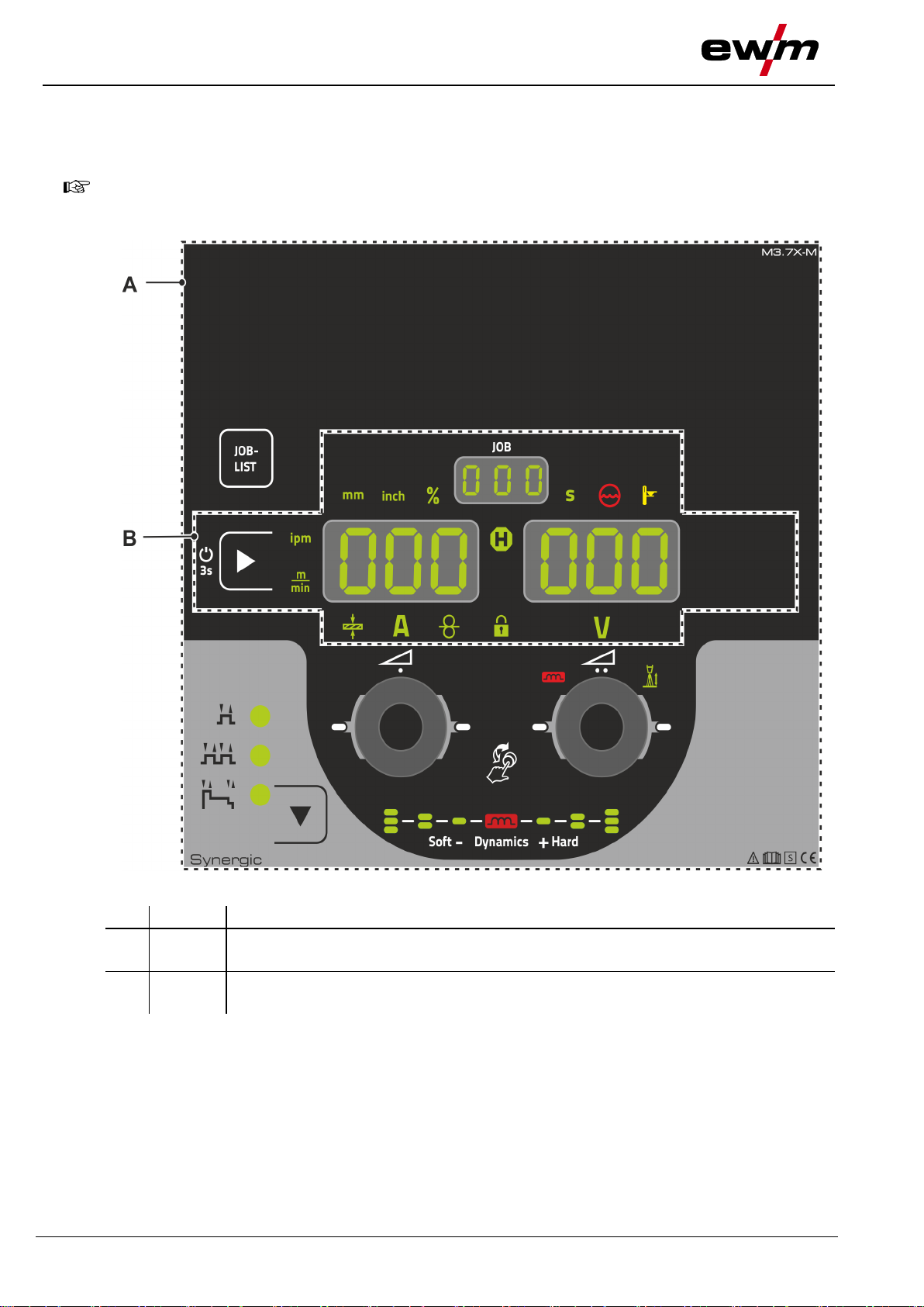
For description purposes, the machine control has been divided into two sections (A, B) to
ensure maximum clarity. The setting ranges for the parameter values are summarised in the
parameter overview section > see 8.1 chapter.
Item
Symbol
Description 0
1
Control section A
> see 4.1.1 chapter
2
Control section B
> see 4.1.2 chapter
4 Machine control – Operating elements
4.1 Overview of control sections
Figure 4-1
Machine control – Operating elements
Overview of control sections
099-0M37XM-EW501
16.07.2018
9
Item
Symbol
Description 0
1
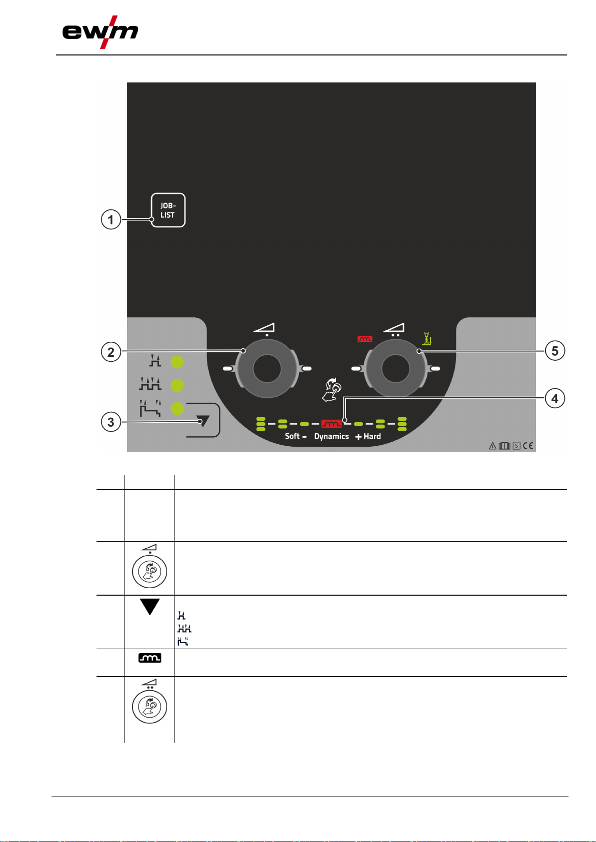
JOB-
LIST
Welding task push-button (JOB)
Select the welding task from the welding task list (JOB-LIST). The list can be found
inside the protective cap on the wire feeder and in the appendix to these operating
instructions.
2
Click wheel welding power
• ----------- Setting the welding power > see 4.3.2 chapter
• ----------- Setting various parameters values depending on the preselection.
The white signal lights (LED) around the rotary knob light up when setting is possible.
3
Operating mode selection push-button
--------- Non-latched
-------- Latched
--------- Special latched
4
Display of arc dynamics
The height and orientation of the set arc dynamics are displayed.
5
Correction of arc length click wheel
• ----------- Setting the arc length correction > see 5.2.1.5 chapter
• ----------- Setting arc dynamics > see 5.2.1.6 chapter
• ----------- Setting various parameters values depending on the preselection.
The white signal lights (LED) around the rotary knob light up when setting is possible.
4.1.1 Control section A
Figure 4-2
Machine control – Operating elements
Overview of control sections
10
099-0M37XM-EW501
16.07.2018
Item
Symbol
Description 0
1
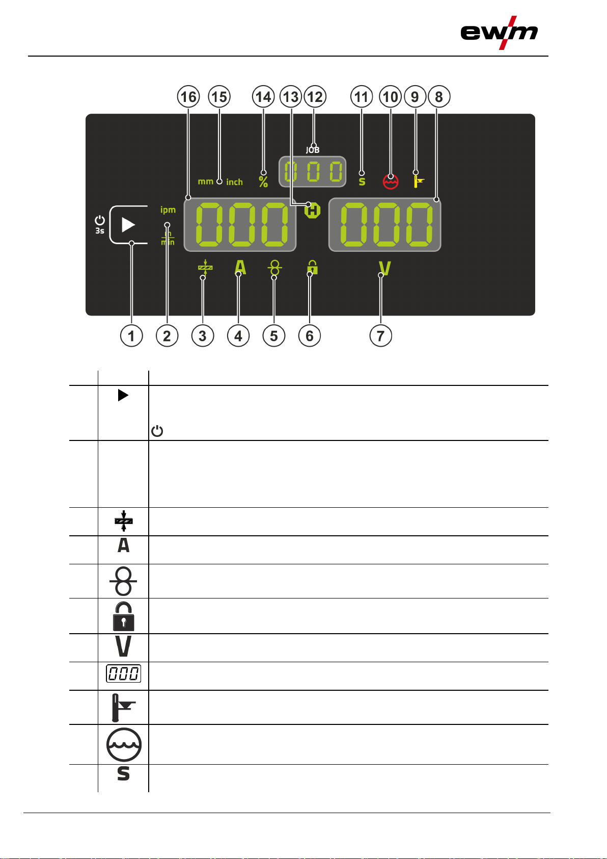
Display left / Lock function push-button
Switching the device display between various welding parameters. Signal lamps show
the selected parameter.
-------- Press for 3 s to put the machine into lock function > see 4.3.5 chapter.
2
Wire feed speed unit signal light
m/min --- Parameter value is displayed in meters per minute.
ipm ------ Parameter value is displayed in inches per minute.
Switching between metric or imperial system via special parameters
"P29" > see 5.4 chapter.
3
Material thickness signal light
Indication of the selected material thickness.
4
Welding current signal light
Display of the welding current in amperes.
5
Signal light, Wire speed
Lights when the wire speed is shown on the display.
6
Lock function signal light
Use display left / lock function push-button to switch on and off.
7
Correction voltage arc length signal light
Display of correction voltage arc length in volts.
8
Display, right > see 4.2 chapter
V --------- welding voltage
9
Excess temperature signal light / Welding torch cooling failure
For error messages > see 6 chapter
10
Coolant fault signal light
Indicates flow fault or low coolant level.
11
Second signal light
The displayed value is displayed in seconds.
4.1.2 Control section B
Figure 4-3
Machine control – Operating elements
Welding data display
099-0M37XM-EW501
16.07.2018
11
Item
Symbol
Description 0
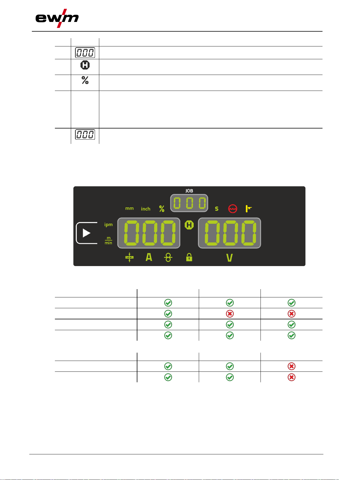
12
JOB number display (welding task) > see 5.2.1 chapter
13
Status display signal light (Hold)
Display of mean values across the entire welding process.
14
Percent signal light
The displayed value is displayed in percent.
15
Material thickness unit signal light
mm ------- Parameter value is displayed in millimeters.
inch ------ Parameter value is displayed in inches.
Switching between metric or imperial system via special parameters
"P29" > see 5.4 chapter.
16
Display, left
Welding current, material thickness, wire speed, hold values
Parameter
Nominal values
[1]
Actual values
[2]
Hold values
[3]
Welding current
Material thickness
Wire feed speed
Welding voltage
Parameter
Nominal values
[1]
Actual values
[2]
Hold values
[3]
Welding current
Welding voltage
4.2 Welding data display
To the left of the parameter displays, there is the parameter selection push-button. It is used to select the
welding parameters to be displayed and their values.
Each time one the button is clicked, the display proceeds to the next parameter (signal lights indicate the
selection). After reaching the last parameter, the system is restarted with the first one.
Figure 4-4
MIG/MAG
MMA
When settings are changed (e.g. wire feed speed) the display immediately switches to the nominal value
setting.
[1]
Nominal values (before welding)
[2]
Actual values (during welding)
[3]
Hold values (after welding, display of mean values for entire welding process)

Machine control – Operating elements
Operating the machine control
12
099-0M37XM-EW501
16.07.2018
4.3 Operating the machine control
4.3.1 Main screen
The machine control switches to the main screen after it has been turned on or a setting has been
completed. This means that the previously selected settings (indicated by signal lights where applicable)
are adopted and that the nominal value for the current (A) is shown in the left-hand welding data display.
The right-hand display shows the nominal value for the welding voltage (V). The control always switches
4.3.2 Welding power setting
4.3.3 Setting advanced welding parameters (Expert menu)
4.3.4 Changing basic settings (machine configuration menu)
4.3.5 Lock function
back to the main screen after 4 sec.
The welding power is adjusted with the welding power rotary knob (click wheel). You can also adjust the
parameters in the operation sequence or settings in the different machine menus.
The Expert menu contains functions and parameters which cannot be set directly in the machine control
or which do not need to be et on a regular basis. The number and display of these parameters depends
on the previously selected welding procedure or the functions. To select them hold the welding power
click wheel (> 2 s). Select the required parameter/menu item by turning (navigating) and pressing the
click wheel.
The basic welding system functions can be adjusted in the machine configuration menu. Only
experienced users should change the settings > see 5.5 chapter.
The lock function protects against accidental adjustment of the device settings.
The user can switch the lock function on or off by pressing the button for a long time from each machine
control or accessory component with the symbol .

Functional characteristics
Operating the machine control
099-0M37XM-EW501
16.07.2018
13
Welding process
Recommended shielding gas quantity
MAG welding
Wire diameter x 11.5 = l/min
MIG brazing
Wire diameter x 11.5 = l/min
MIG welding (aluminium)
Wire diameter x 13.5 = l/min (100 % argon)
TIG
Gas nozzle diameter in mm corresponds to l/min gas throughput
Shielding gas
Factor
75% Ar/25% He
1.14
50% Ar/50% He
1.35
25% Ar/75% He
1.75
100% He
3.16
25s
0
5s
0
300s
5 Functional characteristics
5.1.1 Shielding gas volume settings
If the shielding gas setting is too low or too high, this can introduce air to the weld pool and may cause
pores to form. Adjust the shielding gas quantity to suit the welding task!
• Slowly open the gas cylinder valve.
• Open the pressure regulator.
• Switch on the power source at the main switch.
• Trigger gas test > see 5.1.1.1 chapter function (welding voltage and wire feed motor remain switched
off – no accidental arc ignition).
• Set the relevant gas quantity for the application on the pressure regulator.
Setting instructions
Helium-rich gas mixtures require a higher gas volume!
The table below can be used to correct the gas volume calculated where necessary:
5.1.1.1 Gas test
The operating elements are installed under the protective cap of wire feed mechanism.
5.1.1.2 Purge hose package
The operating elements are installed under the protective cap of wire feed mechanism.
Figure 5-1
Figure 5-2

Functional characteristics
Operating the machine control
14
099-0M37XM-EW501
16.07.2018
+
5.1.1.3 Wire thread
The wire inching function is used for potential- and gas-free inching of the wire electrode after the wire
spool change. By pressing and holding the wire inching button for a long time, the wire inching speed
increases in a ramp function (special parameter P1 > see 5.4.1.1 chapter) from 1 m/min to the set
maximum value. The maximum value is set by simultaneously pressing the wire inching button and
turning the left click wheel.
The operating elements are installed under the protective cap of wire feed mechanism.
5.1.2 Wire return
The wire return function is used to retract the wire electrode without tension and protection gas. By
simultaneously pressing and holding the wire inching and gas test buttons, the wire return speed
increases in a ramp function (special parameter P1 > see 5.4.1.1 chapter) from 1 m/min to the set
maximum value. The maximum value is set by simultaneously pressing the wire inching button and
turning the left click wheel.
During the process, the wire spool must be turned by hand clockwise to wind up the wire electrode again.
The operating elements are installed under the protective cap of wire feed mechanism.
Figure 5-3
Figure 5-4

Functional characteristics
MIG/MAG welding
099-0M37XM-EW501
16.07.2018
15
JOB-LIST
5.2 MIG/MAG welding
5.2.1 Welding task selection
The following steps have to be carried out to select the welding job:
• Select basic parameters (material type, wire diameter and shielding gas type) and welding procedures
(select and enter JOB number by means of JOB-List > see 7.1 chapter).
• Select operating and welding type
• Adjust welding power
• Correct arc length and dynamics if necessary
5.2.1.1 Basic welding parameters
The user must first determine the basic parameters (material type, wire diameter and shielding gas type)
of the welding system. These basic parameters are then compared with the welding job list (JOB-LIST).
The combination of the basic parameters gives a JOB number, which must now be entered on the control
unit. This basic setting must be rechecked or adjusted only when changing the wire or gas.
5.2.1.2 Operating mode
The operating mode determines the process sequence controlled by the welding torch. Detailed
descriptions of the operating modes > see 5.2.4 chapter.
Figure 5-5
Figure 5-6

Functional characteristics
MIG/MAG welding
16
099-0M37XM-EW501
16.07.2018
5.2.1.3 Welding power (operating point)
The welding power is adjusted according to the principle of one-knob operation. The user can set their
operating point optionally as wire feed speed, welding current or material thickness. The optimum welding
voltage for the operating point is calculated and set by the welding machine. If necessary, the user can
correct this welding voltage > see 5.2.1.5 chapter.
5.2.1.4 Accessory components for operating point setting
The operating point can be set at various accessory components as well, such as remote control, special
welding torches or robot and industrial bus interfaces (optional interface for automated welding required,
not available for all machines of this series).
See the operating instructions for the machine in question for a more detailed description of the individual
Figure 5-7
machines and their functions.
5.2.1.5 Arc length
When required, the arc length (welding voltage) can be adjusted for the welding task in hand by +/– 9.9 V.
Figure 5-8

Functional characteristics
MIG/MAG welding
099-0M37XM-EW501
16.07.2018
17
A
B
A
B
A
A
A
A
A
A
B
B
B
B
B
B
Display
Setting/selection
Ignition current
Setting range in percent: depending on main current
Setting range, absolute: Imin to Imax.
5.2.1.6 Arc dynamics (choke effect)
This function can be used to adjust the arc between a narrow, hard arc with deep penetration (positive
values) and a wide and soft arc (negative values). In addition, the selected settings are displayed with
signal lights below the rotary knobs.
5.2.2 Expert menu (MIG/MAG)
The Expert menu has adjustable parameters stored that don’t require regular setting. The number of
parameters shown may be limited, e.g. if a function is deactivated.
Figure 5-9
Figure 5-10

Functional characteristics
MIG/MAG welding
18
099-0M37XM-EW501
16.07.2018
Display
Setting/selection
Correction of arc length in start program P
START
Slope time of start program P
START
to main program PA
Slope time of main program PA to end program P
END
End-crater current
Setting range in percent: depending on main current
Setting range, absolute: Imin to Imax.
Correction of arc length in end program P
END
Burn-back time > see 5.2.2.1 chapter
• ---------- Increase value > increase wire burn-back
• ---------- Decrease value > decrease wire burn-back
Welding wire behaviour
Setting instructions
Wire electrode is sticking in the weld pool.
Increase value
Wire electrode is sticking on the contact tip or large ball
formation on the wire electrode
Reduce value
Symbol
Meaning
Press torch trigger
Release torch trigger
5.2.2.1 Burn-back
The wire burn-back parameter prevents the sticking of the wire electrode in the weld pool or at the contact
tip at the end of the welding process. The value is optimally preset for a variety of applications (but can be
adjusted if necessary). The adjustable value stands for the time until the power source switches off the
welding current after the welding process has been stopped.
5.2.3 Program sequence
Certain materials require special functions for reliable and high-quality welding. In this case, the special
latched mode is used with the following programs:
• Start program P
(avoidance of cold welds at start of seam)
START
• Main program PA (continuous welding)
• End program P
(avoidance of end-craters by targeted heat reduction)
END)
The programs contain parameters such as wire feed speed (operating point), correction of arc length,
slope times, program duration, etc.
Figure 5-11
5.2.4 Operating modes (functional sequences)
5.2.4.1 Explanation of signs and functions

Functional characteristics
MIG/MAG welding
099-0M37XM-EW501
16.07.2018
19
Tap torch trigger (briefly press and release)
Shielding gas is flowing
I
Welding power
Wire electrode is being fed
Wire creep
Wire burn-back
Gas pre-flow
Gas post-flow
Non-latched
Latched
Special latched
t
Time
P
START
Start program
PA
Main program
P
END
End program
The welding machine ends the ignition process or the welding process with an
• ignition fault (no welding current flows within 5 s after the start signal)
• arc interruption (arc is intrerrupted for longer than 5 s)
5.2.4.2 Automatic cut-out

Functional characteristics
MIG/MAG welding
20
099-0M37XM-EW501
16.07.2018
Non-latched mode
Figure 5-12
Step 1
• Press and hold torch trigger.
• Shielding gas is expelled (gas pre-flows).
• Wire feed motor runs at “creep speed”.
• Arc ignites after the wire electrode makes contact with the workpiece; welding current flows.
• Change over to pre-selected wire speed.
Step 2
• Release torch trigger.
• WF motor stops.
• Arc is extinguished after the preselected wire burn-back time expires.
• Gas post-flow time elapses.

Functional characteristics
MIG/MAG welding
099-0M37XM-EW501
16.07.2018
21
Latched mode
Figure 5-13
Step 1
• Press and hold torch trigger
• Shielding gas is expelled (gas pre-flows)
• Wire feed motor runs at “creep speed”.
• Arc ignites after the wire electrode makes contact with the workpiece; welding current flows.
• Change over to pre-selected WF speed (main program PA).
Step 2
• Release torch trigger (no effect)
Step 3
• Press torch trigger (no effect)
Step 4
• Release torch trigger
• WF motor stops.
• Arc is extinguished after the preselected wire burn-back time expires.
• Gas post-flow time elapses.

Functional characteristics
MIG/MAG welding
22
099-0M37XM-EW501
16.07.2018
Latched special
Figure 5-14
1st cycle
• Press and hold torch trigger.
• Shielding gas is flowing (gas pre-flow).
• Wire feed motor runs at “wire creep speed”.
• Arc ignites when the wire electrode makes contact with the workpiece,
welding current is flowing (start program P
START
).
2nd cycle
• Release torch trigger.
• Slope to main program PA.
3rd cycle
• Press and hold torch trigger.
• Slope to end program P
END
.
4th cycle
• Release torch trigger.
• Wire feed motor stops.
• The arc is extinguished once the wire burn-back time has elapsed.
• Gas post-flow time elapses.

Functional characteristics
MMA welding
099-0M37XM-EW501
16.07.2018
23
Operating elements
Functions
Torch trigger
• Start/stop welding
WARNING
Do not carry out any unauthorised repairs or modifications!
To avoid injury and equipment damage, the unit must only be repaired or modified by
specialist, skilled persons!
The warranty becomes null and void in the event of unauthorised interference.
• Appoint only skilled persons for repair work (trained service personnel)!
Dangers resulting from failure to perform test after conversion!
Before reconnection, “Inspection and Testing during Operation” according to
IEC/BS EN 60974-4 “Arc welding systems – Inspection and Testing during Operation”
has to be performed!
• Perform test to IEC / DIN EN 60974-4!
Plug
Function
on X24
Operation with Push/Pull welding torch (factory setting)
on X23
Operation with intermediate drive
5.2.5 Standard MIG/MAG torch
The MIG welding torch trigger is essentially used to start and stop the welding process.
5.2.5.1 Switching between Push/Pull and intermediate drive
The plugs are located directly on the M3.7X printed circuit board.
5.3 MMA welding
5.3.1 Welding task selection
5.3.2 Welding current setting
Figure 5-15
Figure 5-16

Functional characteristics
Special parameters (advanced settings)
24
099-0M37XM-EW501
16.07.2018
A = Hot start current
B = Hot start time
C = Main current
I = Current
t = Time
The Antistick feature prevents the electrode from annealing.
Should the electrode stick despite the Arcforce feature, the machine
automatically switches to the minimum current within approx. one
second. This prevents the electrode from annealing. Check the welding
current setting and correct for the welding task in hand.
5.3.3 Arcforce
Setting:
• Negative values: rutile electrode types
• Values at zero: basic electrode types
Figure 5-17
• Positive values: cellulose electrode types
5.3.4 Hotstart
The function hot start ensures a secure igniting of the arc and a sufficient heating to the still cold parent
metal at the beginning of the welding process. The ignition takes place here with increased current (hot
start current) over a certain time (hot start time).
5.3.5 Antistick
Figure 5-18
Figure 5-19
5.4 Special parameters (advanced settings)
Special parameters (P1 to Pn) are applied for customer-specific configuration of machine functions. This
allows the user maximum flexibility in optimising their requirements.
These settings are not configured directly on the machine control since a regular setting of the
parameters is generally not required. The number of selectable special parameters can deviate between
the machine controls used in the welding system (also see the relevant standard operating instructions).
If required, the special parameters can be reset to the factory settings > see 5.4.2 chapter.

Functional characteristics
Special parameters (advanced settings)
099-0M37XM-EW501
16.07.2018
25
+
A
B
B
A
B
Display
Setting/selection
Wire inching / wire return ramp time
0 = -------- normal inching (10 s ramp time)
1 = -------- fast inching (3 s ramp time) (ex works)
Tapping start for latched and special latched operation
0 = -------- no 4-cycle inching start
1 = -------- 4-cycle inching start possible (ex works)
HOLD function
0 = -------- HOLD values are not displayed
1 = -------- HOLD values are displayed (Ex works)
Correction or nominal voltage display
0 = -------- Correction voltage display (ex works).
1 = -------- Absolute nominal voltage display.
Unit system > see 5.4.1.5 chapter
0 = -------- metric system (ex works)
1 = -------- Imperial system
5.4.1 Selecting, changing and saving parameters
5.4.1.1 Ramp time for wire inching (P1)
The wire inching starts with a speed 1.0 m/min for 2 secs. It is subsequently increased to a ramp function
to 6.0 m/min. The ramp time can be set between two ranges.
During wire inching, the speed can be changed by means of the welding power rotary knob. Changing the
speed has no effect on the ramp time.
Figure 5-20
Functional characteristics
Special parameters (advanced settings)
26
099-0M37XM-EW501
16.07.2018
All special parameters saved by the user will be overwritten by the factory settings!
+
5.4.1.2 Latched/special-latched tap start (P9)
In latched – tap start – operating mode it is possible to switch straight to the second step by tapping the
torch trigger; it is not necessary for current to be flowing.
The welding can be halted by pressing the torch trigger for a second time.
5.4.1.3 Hold function (P15) Hold function active (P15 = 1)
• Mean values for the last main program parameters used for welding are displayed.
Hold function not active (P15 = 0)
• Setpoint values for the main program parameters are displayed.
5.4.1.4 Correction or nominal voltage display (P24)
When setting the arc correction using the right-hand rotary knob the display will either show the correction
voltage +- 9.9 V (ex works) or the absolute nominal voltage.
5.4.1.5 Units system (P29) Function not active
• Metric metric units are displayed.
Function active
5.4.2 Reset to factory settings
• Imperial units are displayed.
Figure 5-21
Functional characteristics
Machine configuration menu
099-0M37XM-EW501
16.07.2018
27
+
B
A
B
A
A
A
A
A
B
B
B
B
B
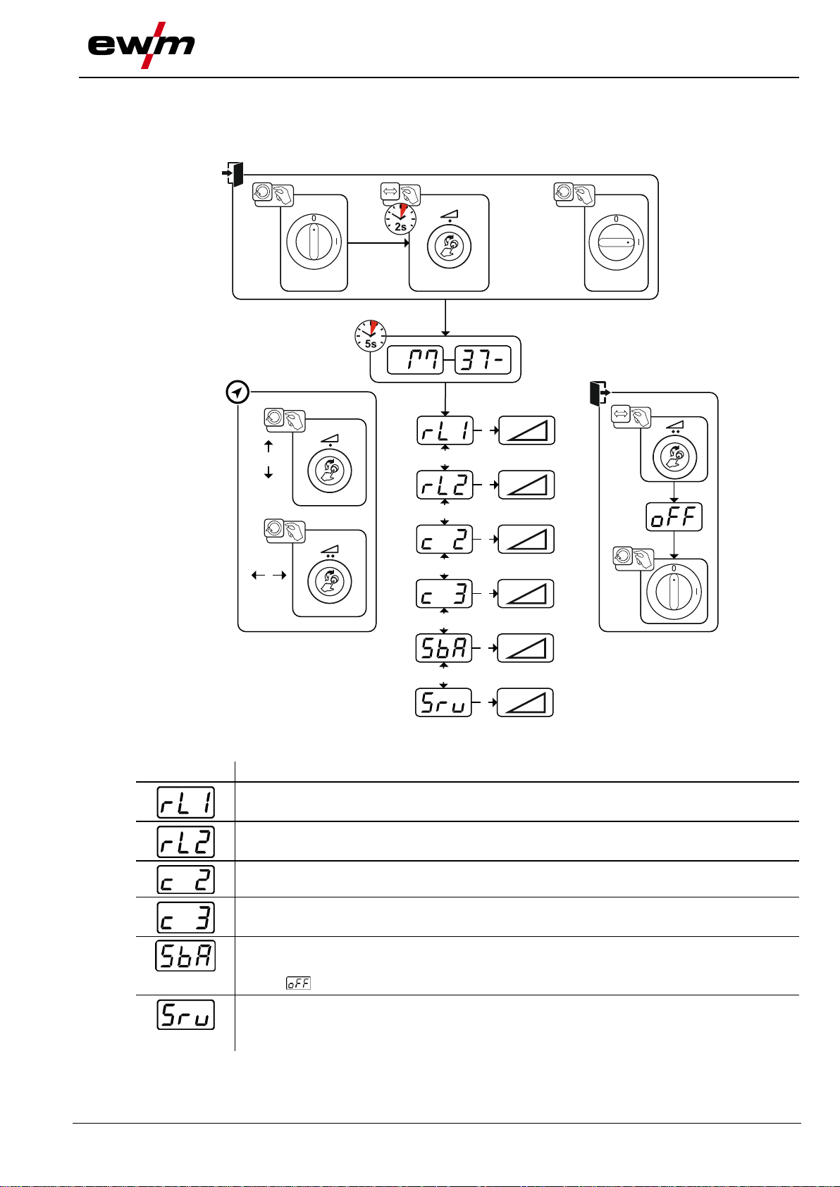
Display
Setting/selection
Lead resistance 1
Lead resistance for the first welding circuit 0 mΩ–60 mΩ (8 mΩ ex works).
Lead resistance 2
Lead resistance for the second welding circuit 0 mΩ–60 mΩ (8 mΩ ex works).
Only qualified service personnel may change the parameters!
Only qualified service personnel may change the parameters!
Time-based power-saving mode > see 5.5.3 chapter
Time to activation of the power-saving mode in case of inactivity.
Setting = disabled or numerical value 5– 60 min. (ex works: 20).
Service menu
Modifications to the service menu may only be carried out by authorised maintenance
staff!
5.5 Machine configuration menu
5.5.1 Selecting, changing and saving parameters
Figure 5-22

Functional characteristics
Machine configuration menu
28
099-0M37XM-EW501
16.07.2018
2
3
4
1
l
0
50mm
l
0
B
A
+
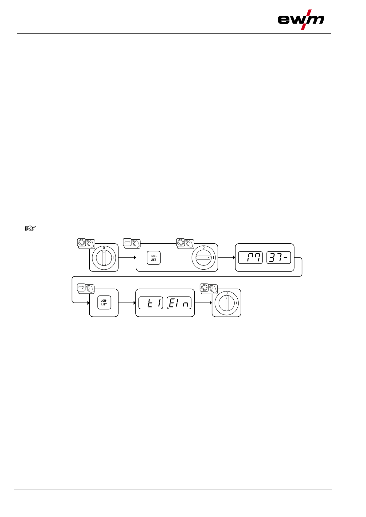
5.5.2 Aligning the cable resistance
The resistance value of the cables can be set directly or it can be adjusted through the power source. The
power source cable resistance value is set to 8 mΩ when delivered. This value corresponds to an earth
cable length of 5 m, an intermediate hose package length of 1.5 m and a water-cooled welding torch
length of 3 m. A +/- welding voltage correction is therefore required to optimise the welding properties for
other hose package lengths. By realigning the cable resistance, the voltage correction value can be set
close to zero again. The electric cable resistance should be realigned whenever an accessory component
such as the welding torch or the intermediate hose package has been changed.
Figure 5-23

Functional characteristics
Machine configuration menu
099-0M37XM-EW501
16.07.2018
29
When power-saving mode is activated, the machine displays show the horizontal digit in the
centre of the display only.
1 Preparation
• Switch off the welding machine.
• Unscrew the gas nozzle from the welding torch.
• Trim the welding wire so that it is flush with the contact tip.
• Retract the welding wire a little (approx. 50 mm) on the wire feeder. There should be no more welding
wire in the contact tip at this point.
2 Configuration
• Press and hold the “Welding power rotary knob”; at the same time switch on the welding machine (at
least 2 s). Release the rotary knob (after a further 5 s the device will switch to the cable resistance 1
parameter).
• Turn the “Welding power rotary knob” to select the appropriate parameter. The “rL1” parameter has to
be adjusted for all machine combinations.
3 Alignment/Measurement
• Applying slight pressure, put the welding torch in place with the contact tip on a clean, purged location
on the workpiece and then press the torch trigger for approx. 2 seconds. A short-circuit current will
flow briefly, which is used to determine and display the cable resistance. The value can be between
0 mΩ and 40 mΩ. The new value is immediately saved without requiring further confirmation. If no
value is shown on the right-hand display, then measurement failed. The measurement must be
repeated.
4 Restoring welding standby mode
• Switch off the welding machine.
• Screw the gas nozzle onto the welding torch.
• Switch on the welding machine.
• Insert the welding wire again.
5.5.3 Power-saving mode (Standby)
You can activate the power-saving mode by setting a parameter in the machine configuration menu (timecontrolled power-saving mode ) > see 5.5 chapter.
Pressing any operating element (e.g. turning a rotary knob) deactivates power-saving mode and the
machine is ready for welding again.

Rectifying faults
Display machine control software version
30
099-0M37XM-EW501
16.07.2018
Error
(Err)
Category
Possible cause
Remedy
a)
b)
c)
1
- - x
Mains overvoltage
Check the mains voltages and compare with
the welding machine connection voltages
2
- - x
Mains undervoltage
3
x - -
Welding machine excess
temperature
Allow the machine to cool down (mains
switch to "1")
4
x x -
Coolant error
Fill coolant
Turn on pump shaft (coolant pump)
Check air cooling unit overcurrent trip
5
x - -
Wire feeder/tachometer error
Check the wire feeder
Tachogenerator is not emitting a signal,
M3.51 defective > inform Service.
6
x - -
Shielding gas error
Check shielding gas supply (for machines
with shielding gas monitoring)
7
- - x
Secondary overvoltage
Inverter error > inform Service
8
- - x
Wire error
Separate the electrical connection between
welding wire and casing or an earthed object
9
x - -
Quick shut-down
Rectify error on robot
(Interface for automated welding)
10
- x -
Arc interruption
Check wire feeding
(Interface for automated welding)
11
- x -
Ignition error (after 5 s)
Check wire feeding
(Interface for automated welding)
13
x - -
Emergency stop deactivation
Check the emergency stop switch at the
interface for automated welding
14
- x -
Wire feeder detection
Check cable connections
ID number allocation error
(2DV)
Correct ID numbers
15
- x -
Second wire feeder detection
Check cable connections
16
- - x
Open circuit voltage reduction
error (VRD)
Inform Service.
17
- x x
Overcurrent detection on wire
feeder
Check ease of wire feeding
18
- x x
Tachogenerator signal error
Check the connection and particularly the
tachogenerator of the second wire feeder
(slave drive).
56
- - x
Mains phase failure
Check mains voltages
6 Rectifying faults
All products are subject to rigorous production checks and final checks. If, despite this, something fails to
work at any time, please check the product using the following flowchart. If none of the fault rectification
procedures described leads to the correct functioning of the product, please inform your authorised
6.1 Display machine control software version
6.2 Error messages (power source)
dealer.
The query of the software versions only serves to inform the authorised service staff. It is available in the
machine configuration menu > see 5.5 chapter.
A welding machine error will be signalled by an error code (see table) on the control display. In
the event of an error, the power unit shuts down.
The display of possible error numbers depends on the machine version (interfaces/functions).
• Document machine errors and inform service staff as necessary.
• If multiple errors occur, these are displayed in succession.
Rectifying faults
Resetting JOBs (welding tasks) to the factory settings
099-0M37XM-EW501
16.07.2018
31
Error
(Err)
Category
Possible cause
Remedy
a)
b)
c)
59
- - x
Machine incompatible
Check machine usage
60
- - x
Software update required
Inform Service.
Welding machine control
Push-button
RC1 / RC2
Expert
Expert 2.0 / Expert XQ 2.0
CarExpert / Progress (M3.11)
alpha Q / Concept / Basic / Basic S / Synergic /
Synergic S / Progress (M3.71) / Picomig 355
not possible
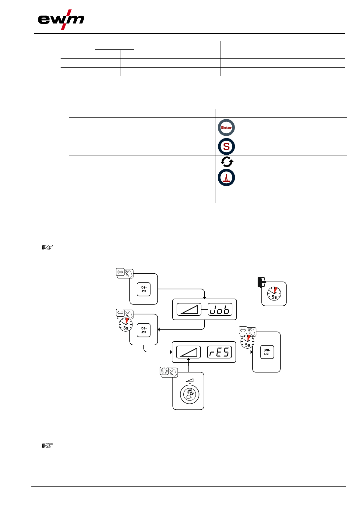
All customised welding parameters that are stored will be replaced by the factory settings.
JOBs 1–128 and 170–256 will be reset.
Custom JOBs 129–169 are maintained.
Categories legend (resetting the error)
a) The error message will disappear once the error has been rectified.
b) The error message can be reset by pressing a push-button:
c) The error message can only be reset by switching the machine off and on again.
6.3 Resetting JOBs (welding tasks) to the factory settings
The shielding gas error (Err 6) can be reset by pressing the "Welding parameters" key button.
6.3.1 Resetting a single JOB
Figure 6-1
6.3.2 Resetting all JOBs

Rectifying faults
Resetting JOBs (welding tasks) to the factory settings
32
099-0M37XM-EW501
16.07.2018
Figure 6-2

Appendix A
JOB-List
099-0M37XM-EW501
16.07.2018
33
7 Appendix A
7.1 JOB-List
Figure 7-1

Appendix B
Parameter overview – setting ranges
34
099-0M37XM-EW501
16.07.2018
Name
Display
Setting range
Code
Standard (ex
works)
Unit
Min. Max.
Ignition current
-
[1]
% 0 - 200
Correction of arc length in start program P
START
-
[1]
V
-9,9 - 9,9
Slope time of start program P
START
to main program PA
-
[1]
s 0 - 20
Slope time of main program PA to end program P
END
-
[1]
s 0 - 20
End-crater current
-
[1]
% 0 - 200
Correction of arc length in end program P
END
-
[1]
V
-9,9 - 9,9
Burn-back time
-
[1]
- 0 - 333
Voltage correction
0 V -9,9 9,9
Wire feed speed, absolute (main program PA)
-
[1]
m/min
0,00 - 20,0
Name
Display
Setting range
Code
Standard (ex
works)
Unit
Min. Max.
Arcforce
0 -40 - 40
8 Appendix B
8.1 Parameter overview – setting ranges
8.1.1 MIG/MAG welding
8.1.2 MMA welding
[1]
depending on the selected welding task (JOB)

Appendix C
Searching for a dealer
099-0M37XM-EW501
16.07.2018
35
9 Appendix C
9.1 Searching for a dealer
www.ewm-group.com/en/specialist-dealers
"More than 400 EWM sales partners worldwide"
Sales & service parteners
 Loading...