

Operating instructions
Power sources for automate d a pplications
alpha Q 352, 552 puls MM
Register now!
For your benefit
Jetzt Registrieren
und Profitieren!
www.ewm-group.com
*Details for ewm-warranty
www.ewm-group.com
*
099-005366-EW501 Observe additional system documents! 31.07.2014

CAUTION
Read the operating instructions !
The operating instructions provide an introduction to the safe use of the products.
•
•
•
• Confirm with a signature where appropriate.
NOTE
A list of authorised sales partners can be found at www.ewm-group.com.
General instructions
Read the operating instructions for all system components!
Observe accident prevention regulations!
Observe all local regulations!
In the event of queries on installation, commissioning, operation or special conditions at the
installation site, or on usage, please contact your sales partner or our
customer service department on +49 2680 181-0.
Liability relating to the operation of this equipment is restricted solely to the function of the equipment. No other
form of liability, regardless of type, shall be accepted. This exclusion of liability shall be deemed accepted by the
user on commissioning the equipment.
The manufacturer is unable to monitor whether or not these instructions or the conditions and methods are
observed during installation, operation, usage and maintenance of the equipment.
An incorrectly performed installation can result in material damage and injure persons as a result. For this reason,
we do not accept any responsibility or liability for losses, damages or costs arising from incorrect installation,
improper operation or incorrect usage and maintenance or any actions connected to this in any way.
© EWM AG · Dr. Günter-Henle-Str. 8 · D-56271 Mündersbach, Germany
The copyright to this document remains the property of the manufacturer.
Reprinting, including extracts, only permitted with written approval.
Subject to technical amendments.

31.07.2014
1 Contents
1
Contents .................................................................................................................................................. 3
2 Safety instructions ................................................................................................................................. 6
2.1 Notes on the use of these operating instructions .......................................................................... 6
2.2 Explanation of icons ....................................................................................................................... 7
2.3 General .......................................................................................................................................... 8
2.4 Transport and installation ............................................................................................................ 12
2.4.1 Lifting by crane ............................................................................................................. 13
2.4.2 Ambient conditions ....................................................................................................... 14
2.4.2.1 In operation ................................................................................................... 14
2.4.2.2 Transport and storage ................................................................................... 14
3 Intended use ......................................................................................................................................... 15
3.1 Applications .................................................................................................................................. 15
3.1.1 MIG/MAG standard welding ......................................................................................... 15
3.1.1.1 forceArc ......................................................................................................... 15
3.1.1.2 rootArc ........................................................................................................... 15
3.1.1.3 coldArc .......................................................................................................... 15
3.1.1.4 pipeSolution .................................................................................................. 15
3.1.2 MIG/MAG pulse welding ............................................................................................... 15
3.1.2.1 forceArc puls ................................................................................................. 15
3.1.2.2 rootArc puls ................................................................................................... 15
3.1.2.3 coldArc puls ................................................................................................... 15
3.1.2.4 superPuls ...................................................................................................... 15
3.2 Documents which also apply ....................................................................................................... 16
3.2.1 Warranty ....................................................................................................................... 16
3.2.2 Declaration of Conformity ............................................................................................. 16
3.2.3 Welding in environments with increased electrical hazards ......................................... 16
3.2.4 Service documents (spare parts and circuit diagrams) ................................................ 16
3.2.5 Calibration/Validation .................................................................................................... 16
4 Machine description – quick overview .............................................................................................. 17
4.1 Front view .................................................................................................................................... 17
4.2 Rear view ..................................................................................................................................... 19
4.3 Machine control – Operating elements ........................................................................................ 21
5 Design and function ............................................................................................................................. 23
5.1 General ........................................................................................................................................ 23
5.2 Connection plan ........................................................................................................................... 25
5.2.1 Legend .......................................................................................................................... 26
5.3 Installation .................................................................................................................................... 27
5.4 Machine cooling ........................................................................................................................... 27
5.5 Workpiece lead, general .............................................................................................................. 27
5.6 Notes on the installation of welding current leads ....................................................................... 28
5.7 Welding torch cooling system ...................................................................................................... 30
5.7.1 List of coolants .............................................................................................................. 30
5.7.2 Maximal hose package length ...................................................................................... 30
5.8 Connect the cooling module to the power source ....................................................................... 31
5.9 Mains connection ......................................................................................................................... 32
5.9.1 Mains configuration ...................................................................................................... 32
5.10 Inter m edi ate hos e pack age connection ....................................................................................... 33
5.11 Matching the cable resistance ..................................................................................................... 34
5.12 Connection for workpiece lead .................................................................................................... 36
5.13 Shielding gas supply (shielding gas cylinder for welding machine) ............................................. 37
5.13.1 Connecting the shielding gas supply ............................................................................ 37
5.13.2 Setting instructions ....................................................................................................... 38
Contents
Notes on the use of these operating instructions
099-005366-EW501
3

Contents
Notes on the use of these operating instructions
31.07.2014
5.14 Interfaces...................................................................................................................................... 39
5.14.1 Connecting the RINT X11 robot interface/BUSINT X11 industrial bus interface .......... 39
5.14.2 RINT X12 robot interface .............................................................................................. 39
5.14.3 BUSINT X11 industrial bus interface ............................................................................ 39
5.14.4 Connecting the PC 300.net welding parameterisation software ................................... 41
5.14.5 Connecting the Q-DOC 9000 welding data documentation software ........................... 42
5.14.6 Connecting the WELDQAS welding data monitoring and documentation system ....... 43
5.14.7 Automation interface ..................................................................................................... 44
5.14.8 Sensor Voltage ............................................................................................................. 46
5.15 Protecting welding parameters from unauthorised access .......................................................... 47
5.15.1 Welding data display ..................................................................................................... 47
5.16 Definition of MIG/MAG welding tasks .......................................................................................... 48
5.16.1 Welding task selection .................................................................................................. 49
5.16.1.1 Selecting or defining a new job ..................................................................... 49
5.16.2 forceArc / forceArc puls ................................................................................................ 50
5.16.3 coldArc / coldArc puls ................................................................................................... 51
5.16.4 pipeSolution .................................................................................................................. 52
5.16.4.1 Operating mode ............................................................................................. 53
5.16.5 Welding type ................................................................................................................. 53
5.16.5.1 Program or control voltage mode .................................................................. 53
5.16.5.2 Program sequence ........................................................................................ 54
5.16.5.3 superPuls ...................................................................................................... 55
5.16.6 MIG/MAG functional sequences / operating modes ..................................................... 56
5.16.6.1 Explanation of signs and functions ................................................................ 56
5.16.7 MIG/MAG program sequence ("Program steps" mode) ............................................... 61
5.16.8 Selection ....................................................................................................................... 61
5.16.9 MIG/MAG overview of parameters for M3.1x ............................................................... 61
5.16.10 Main program A mode .................................................................................................. 62
5.16.10.1 Selection ........................................................................................................ 62
5.16.11 MIG/MAG overview of parameters for M3.1x ............................................................... 63
5.17 "Special Mode" mode ................................................................................................................... 64
5.17.1 Selection ....................................................................................................................... 64
5.17.2 Switching the Hold function on and off ......................................................................... 65
5.17.3 Wire feed speed switching (absolute / relative) ............................................................ 65
5.17.4 Resetting JOBs to status on delivery (Reset ALL) ....................................................... 65
5.17.5 Exiting "Special Mod e" afte r makin g changes .............................................................. 65
5.18 "JOB Info" mode ........................................................................................................................... 66
5.19 Operating time counter ................................................................................................................. 66
5.20 Organising welding tasks (Mode "JOB Manager") ....................................................................... 67
5.20.1 Creating a new JOB in the memory or copying a JOB ................................................. 67
5.20.2 Loading an existing job ................................................................................................. 68
5.20.3 Resetting an existing JOB to the factory setting (Reset JOB) ...................................... 68
5.21 Expert parameters ........................................................................................................................ 69
5.21.1 Selecting expert model parameters .............................................................................. 69
5.21.2 Selecting variables (5 model points) ............................................................................. 69
5.21.3 Setting parameters ....................................................................................................... 69
4
099-005366-EW501

31.07.2014
6 Maintenance, care and disposal ......................................................................................................... 70
6.1 General ........................................................................................................................................ 70
6.2 Maintenance work, intervals ........................................................................................................ 70
6.2.1 Daily maintenance tasks............................................................................................... 70
6.2.1.1 Visual inspection ........................................................................................... 70
6.2.1.2 Functional test ............................................................................................... 70
6.2.2 Monthly maintenance tasks .......................................................................................... 71
6.2.2.1 Visual inspection ........................................................................................... 71
6.2.2.2 Functional test ............................................................................................... 71
6.2.3 Annual test (inspection and testing during operation) .................................................. 71
6.3 Maintenance work ........................................................................................................................ 71
6.4 Disposing of equipment ............................................................................................................... 72
6.4.1 Manufacturer's declaration to the end user .................................................................. 72
6.5 Meeting the requirements of RoHS ............................................................................................. 72
7 Rectifying faults ................................................................................................................................... 73
7.1 Checklist for rectifying faults ........................................................................................................ 73
7.2 Error messages ............................................................................................................................ 75
7.3 Error messages (RC-Panel) ........................................................................................................ 77
7.3.1 Interface for automated welding ................................................................................... 78
7.4 Display machine control software version ................................................................................... 79
7.4.1 Resetting JOBs to status on delivery (Reset ALL) ....................................................... 79
7.5 Vent coolant circuit ....................................................................................................................... 80
8 Technical data ...................................................................................................................................... 81
8.1 alpha Q 352, 552 Puls ................................................................................................................. 81
9 Accessories .......................................................................................................................................... 82
9.1 Connection cables, connection sockets....................................................................................... 82
9.2 General accessories .................................................................................................................... 82
9.3 Options ......................................................................................................................................... 82
9.4 Transport systems ....................................................................................................................... 82
9.5 Interfaces ..................................................................................................................................... 82
9.6 Computer communication ............................................................................................................ 82
9.7 Cooling units ................................................................................................................................ 83
9.8 Wire feed units ............................................................................................................................. 83
10 Circuit diagrams ................................................................................................................................... 84
10.1 alpha Q 352, 552 Puls ................................................................................................................. 84
11 Appendix A ........................................................................................................................................... 86
11.1 JOB-List ....................................................................................................................................... 86
12 Appendix B ........................................................................................................................................... 95
12.1 Overview of EWM branches ........................................................................................................ 95
Contents
Notes on the use of these operating instructions
099-005366-EW501
5
Safety instructions
Notes on the use of these operating instructions
31.07.2014
DANGER
Working or operating procedures which must be closely observed to prevent imminent
• The hazard is also highlighted using a symbol on the edge of the page.
WARNING
Working or operating procedures which must be closely observed to prevent serious
• The hazard is also highlighted using a symbol in the page margin.
CAUTION
• The risk is explained using a symbol on the edge of the page.
CAUTION
Working and operating procedures which must be followed precisely to avoid damaging
• The hazard is explained using a symbol at the edge of the page.
NOTE
• Notes include the "NOTE" keyword in the heading without a general warning symbol.
2 Safety instructions
2.1 Notes on the use of these operating ins tr uc t ions
serious and even fatal injuries.
• Safety notes include the "DANGER" keyword in the heading with a general warning symbol.
and even fatal injuries.
• Safety notes include the "WARNING" keyword in the heading with a general warning
symbol.
Working or operating procedures which must be closely observed to prevent possible
minor personal injury.
• The safety information includes the "CAUTION" keyword in its heading with a general
warning symbol.
or destroying the product.
• The safety information includes the "CAUTION" keyword in its heading without a general
warning symbol.
Special technical points which users mu st observe.
Instructions and lists detailing step-by-step actions for given situations can be recognised via bullet
points, e.g.:
• Insert the welding current lead socket into the relevant socket and lock.
6
099-005366-EW501
31.07.2014
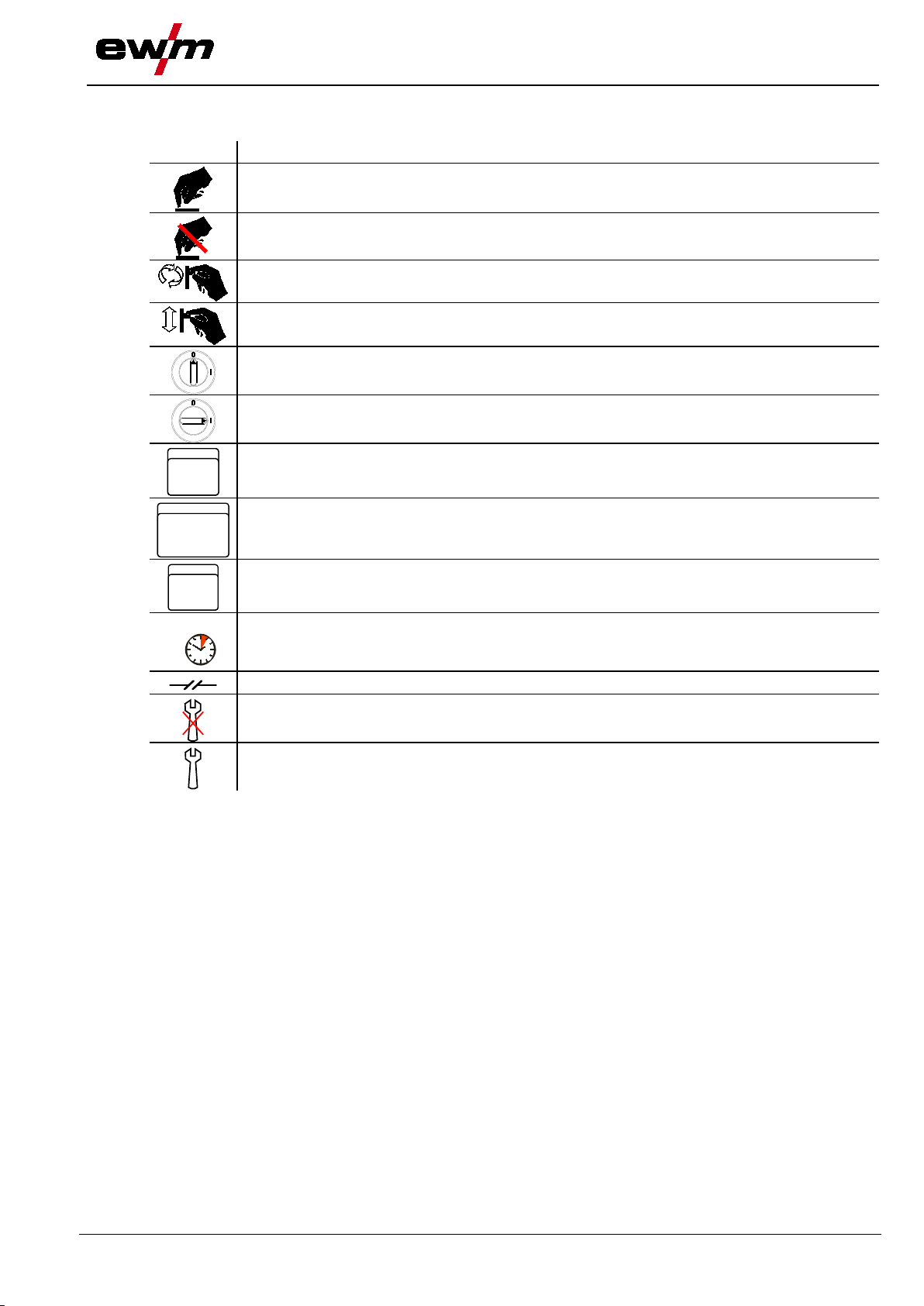
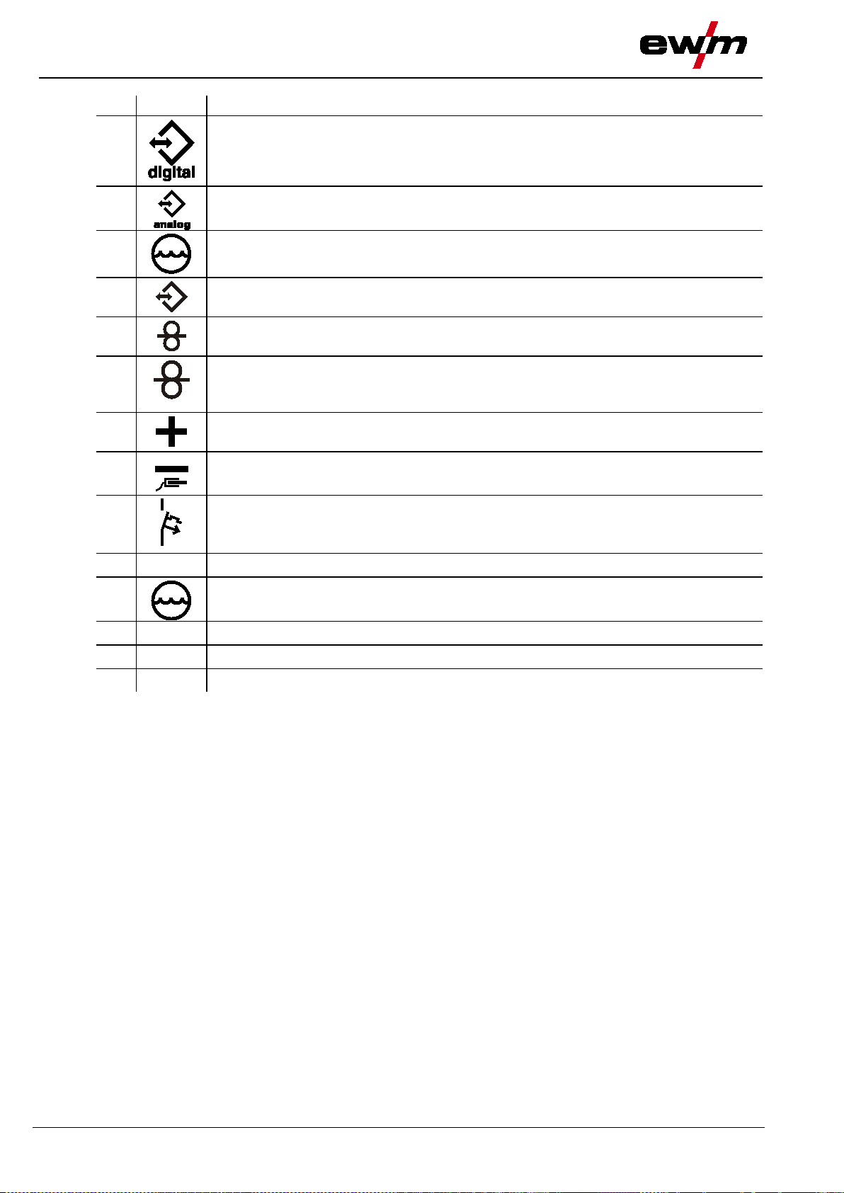
Symbol
Description
Turn
Switch on machine
ENTERENTER
ENTER (enter the menu)
NAVIGATION
EXIT
EXIT (Exit the menu)
4 s
Interruption in the menu display (other setting options possible)
Tool not required/do not use
2.2 Explanation of icons
Press
Do not press
Switch
Switch off machine
Safety instructions
Explanation of icons
NAVIGATION (Navigating in the menu)
Time display (example: wait 4s/press)
Tool required/use
099-005366-EW501
7

Safety instructions
General
31.07.2014
DANGER
Electric shock!
Welding machines use high voltages which can result in potentially fatal electric shocks
• Wait for 4 minutes until the capacitors have discharged!
necessary).
Do not carry out any unauthorised repairs or modifications!
• Appoint only skilled persons for repair work (trained service personnel)!
WARNING
Risk of accidents if these safety instructions are not observed!
• Inform persons in the working area that they must observe the regulations!
safety curtains!
2.3 General
and burns on contact. Even low voltages c an cause you to get a shock and lead to
accidents.
• Do not touch any live parts in or on the machine!
• Connection cables and leads must be free of faults!
• Switching off alone is not sufficient!
• Place welding torch and stick electrode holder on an insulated surface!
• The unit should only be opened by specialist staff after the mains plug has been unplugged!
• Only wear dry protective clothing!
Electromagnetic fields!
The power source may cause electrical or electromagnetic fields to be produced which
could affect the correct functioning of electronic equipment such as IT or CNC devices,
telecommunication lines, power cables, signal lines and pacemakers.
• Observe the maintenance instr uc tions "See 6 Maintenance, care and disp osal chapter"!
• Unwind welding leads completely!
• Shield devices or equipment sensitive to radiation accordingly!
• The correct functioning of pacemakers may be affected (obtain advice from a doc tor if
To avoid injury and equipment damage, the unit must only be repaired or modified by
specialist, skilled persons!
The warranty becomes null and void in the event of unauthorised interference.
Non-observance of these safety instructions is potentially fatal!
• Carefully read the safety information in this manual!
• Observe the accident prevention regulations in your country.
Risk of injury due to radiation or heat!
Arc radiation results in injury to skin and eyes.
Contact with hot workpieces and sparks results in burns.
• Use welding shield or welding helmet with the appropriate safety level (depending on the
application)!
• Wear dry protective clothing (e.g. welding shield, gloves, etc.) according to the relevant
regulations in the country in question!
• Protect persons not involved in the work against arc beams and the risk of glare using
8
099-005366-EW501
Safety instructions
General
31.07.2014
WARNING
excessive pressure
• Never heat explosive liquids, dusts or gases by welding or cutting!
Smoke and gases!
• Wear suitable breathing apparatus if appropriate!
• Connect welding leads correctly!
Danger when coupling multiple power sources!
AC welding, as a minor error in operation can cause the welding voltages to be combined.
CAUTION
Noise exposure!
• Persons located within the working area must wear suitable ear protection!
Explosion risk!
Apparently harmless substances in closed containers may generate
when heated.
• Move containers with inflammable or explosive liquids away from the working area!
Smoke and gases can lead to breathing difficulties and poisoning. In addition, solvent
vapour (chlorinated hydrocarbon) may be converted into poisonous phosgene due to
the ultraviolet radiation of the arc!
• Ensure that there is sufficient fresh air!
• Keep solvent vapour away from the arc beam field!
Fire hazard!
Flames may arise as a result of the high temperatures, stray sparks, glowing-hot parts
and hot slag produced during the welding process.
Stray welding currents can also result in flames forming!
• Check for fire hazards in the working area!
• Do not carry any easily flammable objects such as matches or lighters.
• Keep appropriate fire extinguishing equipment to hand in the working area!
• Thoroughly remove any residue of flammable substances from the workpiece before
starting welding.
• Only continue work on welded workpieces once they have cooled down.
Do not allow to come into contact with flammable material!
Coupling multiple power sources in parallel or in series has to be carried out by
qualified personnel and in accordance with the manufacturer's guidelines. Before
bringing the power sources
that they cannot exceed the maximum allowed open circuit voltage.
• Connection of the machine
• When decommissioning individual power
to be safely disconnected from the welding system as a whole. (Danger due to inverse
voltages
!)
• Do not couple welding machines with pole reversing switch (PWS series) or machines for
Noise exceeding 70 dBA can cause permanent hearing damage!
• Wear suitable ear protection!
into service for arc welding operations, a test has to verify
may be carried out by qualified personnel only!
sources, all mains and welding current leads have
099-005366-EW501
9

Safety instructions
General
31.07.2014
CAUTION
• Regular checks of the machine according to IEC 60974-4.
machine is switched off.
Damage to the machine due to stray welding c urrents!
Stray welding currents can destro y protective earth conductors, damage equipment and
not in use!
the machine can be connected.
Obligations of the operator!
The respective national directives and laws must be observed for operation of the
machine!
• National implementation of the framework directive (89/391/EWG), as well as the
associated individual directives.
• In particular, directive (89/655/EWG), on the minimum regulations for safety and health
protection when staff members use equipment during work.
• The regulations regarding work safety and accident prevention for the respective country.
• Setting up and operating the machine according to IEC 60974-9.
• Check at regular intervals that users are working in a safety-conscious way.
Damage due to the use of non-genuine parts!
The manufacturer's warranty becomes voi d if non-genuine parts are used!
• Only use system components and options (power sources, welding torches, electrode
holders, remote controls, spare parts and replacement parts, etc.) from our range of
products!
• Only insert and lock accessory components into the relevant connection socket when the
electronic devices and cause overheating of components leading to fire.
• Make sure all welding leads are securely connected and check regularly.
• Always ensure a proper and secure electrical connection to the workpiece!
• Set up, attach or suspend all conductive power source components like casing, transport
vehicle and crane frames so they are insulated!
• Do not place any other electronic devices such as drillers or angle grinders, etc., on the
power source, transport vehicle or crane frames unless they are insulated!
• Always put welding torches and electrode holders on an insulated surface when they are
Mains connection
Requirements for connection to the public mains network
High-performance machines can influence the mains quality by taking current from the mains
network. For some types of machines, connection restrictions or requirements relating to the
maximum possible line impedance or the necessary minimum supply capacity at the interface
with the public network (Point of Common Coupling, PCC) can therefore apply. In this respect,
attention is also drawn to the machines' technical data. In this case, it is the responsibility of
the operator, where necessary in consultation with the mains network operator, to ensure that
10
099-005366-EW501

Safety instructions
General
31.07.2014
CAUTION
10, welding machines are grouped in two electromagnetic
• Shielding from other equipment in the surrounding area or the entire welding system
EMC Machine Classification
In accordance with IEC 60974compatibility classes "See 8 Technical data chapter":
Class A machines are not inten ded for use in reside nt ial areas where the power supply comes
from the low-voltage public mains network. When ensuring the electromagnetic compatibility of
class A machines, difficulties can arise in these areas due to interference not only in the supply
lines but also in the form of radiated interference.
Class B machines fulfil the EMC requirements in industrial as well as residential areas,
including residential areas connected to the low-voltage public mains network.
Setting up and operating
When operating arc welding systems, in some cases, electro-magnetic interference can occur
although all of the welding machines comply with the emission limits specified in the standard.
The user is responsible for any interference caused by welding.
In order to evaluate any po s s ible problems with electromagnetic compatibility in the
surrounding area, the user must consider the following: (see also EN 60974-10 Appendix A)
• Mains, control, signal and telecommunication lines
• Radios and televisions
• Computers and other control systems
• Safety equipment
• The health of neighbouring persons, especially if they have a pacemaker or wear a hearing
aid
• Calibration and measuring equ ipm ent
• The immunity to interference of other equipment in the surrounding area
• The time of day at which the welding work must be carried out
Recommendations for reducing interference emission
• Mains connection, e.g. additional mains filter or shielding with a metal tube
• Maintenance of the arc welding equipment
• Welding leads should be as short as possible and run closely together along the ground
• Potential equalization
• Earthing of the workpiece. In cases where it is not possible to earth the workpiece directly,
it should be connected by means of suitable capacitors.
099-005366-EW501
11

Safety instructions
Transport and installation
31.07.2014
WARNING
Incorrect handling of shielding gas cylinders!
• Avoid heating the shielding gas cylinder!
CAUTION
There is a risk of the machine tipping over and injuring persons or being damaged itself
• Fix external wire feed units during transport (avoid uncontrolled rotation)!
• Disconnect supply lines!
CAUTION
• Only transport and operate in an upright position!
2.4 Transport and installation
Incorrect handling of shielding gas cylinders can result in serious and even fatal injury.
• Observe the instructions from the gas manufacturer and in any relevant regulations
concerning the use of compressed air!
• Place shielding gas cylinders in the holders provided for them and secure with fixing
devices.
Risk of tipping!
during movement and set up. Tilt resistance is guaranteed up to an angle of 10°
(according to EN 60974-A2).
• Set up and transport the machine on level, solid ground!
• Secure add-on parts using suitab le equip ment !
• Replace damaged wheels and their fixing elements!
Damage due to supply lines not being disconnected!
During transport, supply lines which have not been disconnected (mains supply leads,
control leads, etc.) may cause hazards such as connected equipment tipping over and
injuring persons!
Equipment damage when not operated in an upright position!
The units are designed for operation in a n u p rig h t position!
Operation in non-permissible positions can cause equipment damage.
12
099-005366-EW501

31.07.2014
WARNING
Risk of injury during lifting by crane!
or mount-on components.
Craning principle
• Avoid lateral loading of the lifting eyes!
2.4.1 Lifting by crane
When lifting the machine by crane, persons may be severely injured by falling machines
• Simultaneous lifting of system components such as power source, wire
feeder or cooling unit
be lifted separately!
• Remove any supply leads and accessories before lifting by crane
hose package
remote control,etc.)!)
• Properly close and lock all casing covers and protective caps
lifting by crane!
• Use the correct number of hoisting equipment of the right size and
right capacity! Observe craning principle (see figure)!
• For machines with lifting eyes: always lift all lifting eyes simultaneously!
• When using retrofitted craning frames etc.: always use at least two
lifting points positioned as far apart as possible – observe option
description.
• Avoid any jerky movements!
• Ensure that the load is
chain slings of the same length only!
• Stay outside the danger zone underneath the machine!
• Observe the regulations regarding occupational safety and accident
prevention for the respective country.
Safety instructions
Transport and installation
is not allowed. Each system component has to
(e.g.
, wire spool, shie ld in g gas cylinder, toolbox, wire feeder,
before
distributed evenly! • Use chain hoists and
Risk of injury due to unsuitable lifting eye!
In case of improper use of lifting eyes or the use of unsuitable lifting eyes, persons can
be seriously damaged by falling equipment or add-on components!
• The lifting eye must be completely screwed in!
• The lifting eye must be positioned flat onto and in full contact with the supporting surfaces!
• Check that the lifting eyes are securely fastened before use and check for any damage
(corrosion, deformation)!
• Do not use or screw in damaged lifting eyes!
099-005366-EW501
13

Safety instructions
Transport and installation
31.07.2014
CAUTION
Installation site!
CAUTION
• Avoid ambient air containing salt (sea air)!
Non-permissible ambient conditions!
• Observe the minimum distance of 0.5 m from obstacles!
2.4.2 Ambient conditions
The machine must not be operated in the open air and must only be set up and
operated on a suitable, stable and level base!
• The operator must ensure that the ground is non-slip and level, and provide sufficient
lighting for the place of work.
• Safe operation of the machine must be guaranteed at all times.
Equipment damage due to dirt accumulation!
Unusually high quantities of dust, acid, corrosive gases or substances may damage the
equipment.
• Avoid high volumes of smoke, vapour, oil vapour and grinding dust!
Insufficient ventilation results in a reduction in performance and equipment damage.
• Observe the ambient conditions!
• Keep the cooling air inlet and outlet clear!
2.4.2.1 In operation Temperature range of the ambient air:
• -25 °C to +40 °C
Relative air humidity:
• Up to 50% at 40 °C
• Up to 90% at 20 °C
2.4.2.2 Transport and storage Storage in an enclosed space, temperature range of the ambient air:
• -30 °C to +70 °C
Relative air humidity
• Up to 90% at 20 °C
14
099-005366-EW501

31.07.2014
WARNING
• Do not modify or convert the equipment improperly!
3 Intended use
Hazards due to improper usage!
Hazards may arise for persons, animals and material objects if the equipment is not
used correctly. No liability is accepted for any damages arising from improper u sag e!
• The equipment must only be used in line with proper usage and by trained or expert staff!
3.1 Applications
3.1.1 MIG/MAG standard welding
Metal arc welding using a wire electrode whereby gas from an external source surrounds the arc and the
molten pool to protect them from the atmosphere.
3.1.1.1 forceArc
Heat-reduced, directionally stable and powerful arc with deep penetration for the higher performance
range. Non-alloyed, low-alloy and high-alloy steels and high-tensile fine-grained steels
3.1.1.2 rootArc
Short arc with perfect weld modelling capabilities for effortless gap bridging and positional welding
3.1.1.3 coldArc
Heat-reduced, low-spatter short arc for high dimensional stability welding and brazing, plus root welding
with excellent gap bridging capab iliti es .
3.1.1.4 pipeSolution
Reduced-energy MAG welding. X-ray-proof welding of pipelines and pipework without lack of fusion. Root
pass and fill and final pass with or without air gap. Low- and high-alloy steels with solid and cored wires.
3.1.2 MIG/MAG pulse welding
Welding process for optimum welding results when joining stainless steel and aluminium thanks to
controlled drop transfer and targeted, adapted heat input.
3.1.2.1 forceArc puls
Effective addition to the forceArc arc, perfect for welding final passes in all performance classes and all
positions.
3.1.2.2 rootArc puls
The perfect enhancement for focused heat input for the higher performance range
3.1.2.3 coldArc puls
The optimum enhancement for the higher performance range, with focused heat input exactly where the
heat is required.
3.1.2.4 superPuls
The EWM superPuls function enables automatic switching between two operating points in a process.
Intended use
Applications
099-005366-EW501
15
Intended use
Documents which also apply
31.07.2014
NOTE
For further information, please see th e accompanying supplementary sheets "Machine
and Company Data, Maintenance and Testing, Warranty"!
The designated machine conforms to EC Directives and standards in terms of its design
and construction:
•
• EC EMC Directive (2004/108/EC),
This declaration shall become null and void in the event of unauthorised modifications, improperly
conducted repairs, non
conversion work not specifically authorised by the manufacturer.
The original copy of the declaration of conformity is enclosed with the unit.
In compliance with
environments with an increased electrical hazard.
DANGER
• Appoint only skilled persons for repair work (trained service personnel)!
3.2 Documents which also apply
3.2.1 Warranty
3.2.2 Declaration of Conformity
EC Low Voltage Directive (2006/95/EC),
-observance of the deadlines for the repetition test and / or non-permitted
3.2.3 Welding in environments with increased electrical hazards
IEC / DIN EN 60974, VDE 0544 the machines can be used in
3.2.4 Service documents (spare parts and circuit diagrams)
Do not carry out any unauthorised repai rs o r modifications!
To avoid injury and equipment damage, the unit must only be repaired or modified by
specialist, skilled persons!
The warranty becomes null and void in the event of unauthorised interference.
Original copies of the circuit diagrams are enclosed with the unit.
Spare parts can be obtained from the relevant authorised dealer.
3.2.5 Calibration/Validation
We hereby confirm that this machine has been tested using calibrated measuring equipment, as
stipulated in IEC/EN 60974, ISO/EN 17662, EN 50504, and complies with the admissible tolerances.
Recommended calibration i nter v al: 12 months
16
099-005366-EW501
Machine description – quick overview
31.07.2014
4 Machine description – quick overview
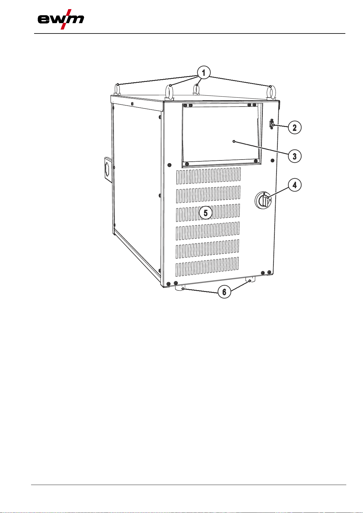
4.1 Front view
Front view
Figure 4-1
099-005366-EW501
17

Machine description
– quick overview
Front view
31.07.2014
Item
Symbol
Description 0
Lifting lug
"See 4.3 Machine control – Operating elements chapter“
Main switch, machine on/off
5 Cooling air inlet
Machine feet
1
2
PC interface, serial (D-Sub connection socket, 9-pole)
3
4
6
Machine control
18
099-005366-EW501

31.07.2014
4.2 Rear view
Machine description – quick overview
Rear view
Figure 4-2
099-005366-EW501
19
Machine description
– quick overview
Rear view
31.07.2014
Item
Symbol
Description 0
Interfaces (customer specific)
7-pole connection socket (digital)
For connecting digital accessory components
7-pole connection socket (digital)
Wire feed unit connection
welding torch and the power source
Welding current connection on wire feed unit
press to reset a triggered fuse
11 Connection socket, 5-pole
Intermediate hose package strain relief
14
1
• RINTX12 robot interface
• BUSINTX11 industrial bus inter fac e
2
3
4
5
6
7
8
9
10 Mains connection cable
19-pole mechanised welding interface (analogue)
"See 5.14.7 Automation interface chapter"
8-pole connection socket
Cooling unit control lead
12-pole connection socket (analogue)
Connection socket for analogue control signals (collision protection, etc. ) between the
Connector plug, welding current "+"
Connection socket, “-” welding current
Workpiece connection
Key button, automatic cutout
Wire feed motor supply voltage fuse
Cooling unit voltage supply
12
13 Cooling air outlet
Machine feet
20
099-005366-EW501
Machine description – quick overview
31.07.2014
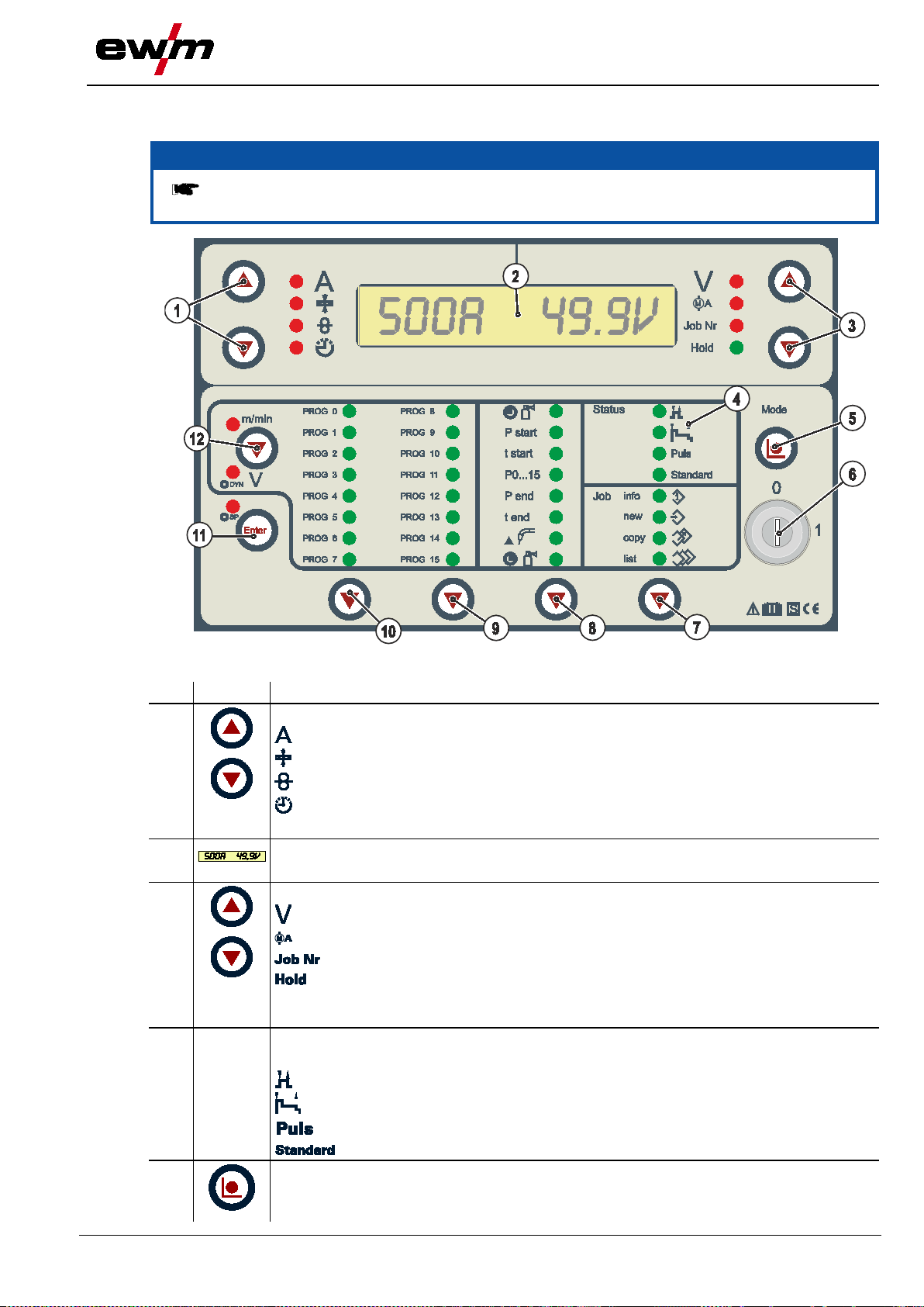
NOTE
as in the power source!
Item
Symbol
Description 0
Buttons switching digital display, left
Selection of further welding parameters in lower programming levels.
Display, 16-digit
Display of all welding parameters and their values
Switching of the digital display Buttons, right
Standard welding
(program steps mode, main program A mode, JOB Manager, JOB Info)
4.3 Machine control – Operating elements
The device controller may be install ed both in an external wired remote Control as well
Machine control – Operating elements
1
2
3
4
Figure 4-3
Welding current (nominal, actual and hold values)
Material thickness (nominal value)
Wire speed (nominal, actual and hold values)
Operating hour counter
Welding voltage (nominal / actual values)
Motor current (actual value)
JOB number
After each completed welding process, the last parameter values used for the
welding process are shown on the display in the main program; the signal
light is on.
Status
Display of the current parameters specified by the robot control.
Non-latched
Special, non-latched
Pulse welding
5
Button, Mode
Select further programming levels
099-005366-EW501
21

Machine description
– quick overview
Machine control
31.07.2014
Item
Symbol
Description 0
Key switch for protection against unauthorised use
Button, "Program sequence"
the welding process.
the welding process.
"ENTER" button
Superpuls
Button, "Program A" (operating point)
Dynamics (signal light flashing)
– Operating elements
6
Position “1” > changes possible,
Position “0” > changes not possible.
"See 5.15 Protecting welding parameters from unauthorised access chapter".
7
8
9
"JOB Manager" button (organise welding tasks)
During operation, the current position in the program sequence is shown.
Outside, the values can be selected and welding parameters changed by means of the
rotary dial.
Button, "Program selection 8 to 15"
Display the selected program during the welding process and select program outside
Display information on the current welding task selected
Define new welding task
Copy welding task
Display information on any welding task (job)
Gas pre-flows (0.0 to 20.0 sec)
Start program (WFstart 0% to 200% / Ustart)
Start time (0.0 to 20.0 sec)
Current program display
End program (0% to 200%)
End time (0.0 to 20.0 sec)
Wire burn-back (2 to 500)
Gas post-flow time (0.0 s to 20.0 s)
10
11
12
Button, "Program selection 0 to 7"
Display the selected program during the welding process and select program outside
Confirmation, e.g.: of JOB parameters
Wire speed
Voltage correction
22
099-005366-EW501

General
31.07.2014
WARNING
Risk of injury from electric shock!
interfaces) may only be connected when the machine is switched off!
CAUTION
Not all active parts of the welding current circuit can be shielded from direct contact. To
• Always place torches and electrode holders on an insulated surface!
if necessary.
Risk of injury due to moving parts!
• Keep casing covers or protective caps closed during operation!
• Keep all casing covers or protective caps closed during operation!
Risk from electrical current!
surface before starting work and during breaks.
5 Design and function
Design and function
5.1 General
Contact with live parts, e.g. weldin g current sockets, is potentially fatal!
• Follow safety instructions on the opening pages of the operating instructions.
• Commissioning may only be carried out by persons who have the relevant expertise of
working with arc welding machines!
• Connection and welding leads (e.g. electrode holder, welding torch, workpiece lead,
Insulate the arc welder from welding voltage!
avoid any associated risks it is vital for the welder to adhere to the relevant safety
regulations. Even low voltages can cause a shock and lead to accidents.
• Wear dry and undamaged protective clothing (shoes with rubber soles/welder's gloves
made from leather without any studs or braces)!
• Avoid direct contact with non-insulated connection sockets or connectors!
Risk of burns on the welding current connection!
If the welding current connections are not locked, connections and leads heat up an d
can cause burns, if touched!
• Check the welding current connections every day and lock by turning in clockwise direction,
The wire feeders are equipped with moving parts, which can trap hands, hair, clothing
or tools and thus injure persons!
• Do not reach into rotating or moving parts or drive components!
Risk of injury due to welding wire escaping in an unpredictable manner!
Welding wire can be conveyed at very high speeds and, if conveyed incorrectly, may
escape in an uncontrolled manner and i n jure persons!
• Before mains connection, set up the complete wire guide system from the wire spool to the
welding torch!
• Remove the pressure rollers from the wire feeder if no welding torch is fitted!
• Check wire guide at regular intervals!
If welding is carried out alternately using different methods and if a welding torch and
an electrode holder remain connected to the machine, the open-circuit/welding voltage
is applied simultaneously on all cables.
• The torch and the electrode holder should therefore always be placed on an insulated
099-005366-EW501
23

Design and function
General
31.07.2014
CAUTION
• Accessory components are detected automatically after the power source is switched on.
NOTE
Observe documentation of other sy stem components when connecting!
Damage due to incorrect connection!
Accessory components and the power source itself can be damaged by incorrect
connection!
• Only insert and lock accessory components into the relevant connection socket when the
machine is switched off.
• Comprehensive descriptions can be found in the operating instructions for the relevant
accessory components.
Using protective dust caps!
Protective dust caps protect the connection sockets and therefore the machine against
dirt and damage.
• The protective dust cap must be fitted if there is no accessory component being operated
on that connection.
• The cap must be replaced if faulty or if lost!
24
099-005366-EW501

31.07.2014
3~
AC
Cool 82
M drive 4 Rob 2
AC
Fassförderung
7
pol
12
pol
5
pol
8
pol5pol
SPS / CU / ROB
19
pol
RINTX12
BUSINTX11
7
pol
12
pol
7
pol
19
pol
19
pol
AIR
AIR
8
pol
AIR
HP
HP
HP
5.2 Connection plan
Design and function
Connection plan
099-005366-EW501
Figure 5-1
25

Design and function
Connection plan
31.07.2014
Shielding gas
Welding torch coolant
Cooling water input
3~
AC
19
pol
19-pole mechanised welding interface
12
pol
Wire feed unit control lead (12-pole)
7
pol
Wire feed unit control lead/RINTX12, BUSINTX11 (7-pole)
5
pol
Cooling unit supply voltage connection (5-pole)
8
pol
Cooling unit control lead (8-pole)
AIR
HP
5.2.1 Legend
Wire feed
Welding current (minus potential, workpiece)
Cooling water output
Welding machine supply voltage
Welding current (plus potential)
Euro torch connector
Compressed air connection to clean the welding torch nozzles
Hose package (HP = hose package)
26
099-005366-EW501
31.07.2014
CAUTION
Installation site!
• Safe operation of the machine must be guaranteed at all times.
CAUTION
• Take care to ensure faultless power connections!
5.3 Installation
The machine must not be operated in the open air and must only be set up and
operated on a suitable, stable and level base!
• The operator must ensure that the ground is non-slip and level, and provide sufficient
lighting for the place of work.
5.4 Machine cooling
To obtain an optimal duty cycle from the power components, the following precautions should be
observed:
• Ensure that the working area is adequately ventilated.
• Do not obstruct the air inlets and outlets of the machine.
• Do not allow metal parts, dust or other objects to get into the machine.
5.5 Workpiece lead, general
Design and function
Installation
Risk of burns due to incorrect connection of the workpiece lead!
Paint, rust and dirt on the connec tion restrict the power flow and may lead to stra y
welding currents.
Stray welding currents may cause fires and injuries!
• Clean the connections!
• Fix the workpiece lead securely!
• Do not use structural parts of the workpiece as a return lead for the welding current!
099-005366-EW501
27

Design and function
Notes on the installation of welding current leads
31.07.2014
NOTE
Incorrectly installed welding current leads can cause faults in the arc (flickering).
Lay the workpiece lead and hose package of power sources without HF igniter
(MIG/MAG) for as long and as close as possible in parallel.
long as possible in parallel with a distance of 20 cm to avoid HF sparkover.
Always keep a distance of at least 20 cm to leads of other power sources to avoid
interferences.
5.6 Notes on the installation of wel ding current leads
Lay the workpiece lead and hose package of power sources with HF igniter (TIG) for as
Figure 5-2
28
099-005366-EW501

Design and function
31.07.2014
NOTE
Use an individual welding lead to the workpiece for each welding machine!
NOTE
packages. Avoid loops!
Always keep leads as short as possible!
Lay any excess cable lengths in meanders.
Figure 5-3
Fully unroll welding current lead s, torch hose packages and intermediate hose
Notes on the installation of welding current leads
Figure 5-4
099-005366-EW501
29

Design and function
Welding torch cooling system
31.07.2014
CAUTION
Coolant mixtures!
• When changing the coolant, the entire volume of liquid must be changed.
that the frost protection is adequate to prevent damage to the machine or the accessory
• Replace coolant as necessary if frost protection is inadequate!
NOTE
The disposal of coolant must be carr ied o u t according to official regulations and
• Recommended cleaning agent: water, if necessary with cleaning agent added.
Coolant
Temperature range
KF 23E (Standard)
-10 °C to +40 °C
KF 37E
-20 °C to +10 °C
Pump 3.5 bar
Pump 4.5 bar
drive (example. miniDrive)
intermediate drive (example: miniDrive)
5.7 Welding torch cooling s yst e m
Mixtures with other liquids or the use of unsuitable coolants result in material damage
and renders the manufacturer's warranty void!
• Only use the coolant described in this manual (overview of coolants).
• Do not mix different coolants.
Insufficient frost protection in the welding torch coolant!
Depending on the ambient conditions, different liquids are used for cooli n g the welding
torch "See 5.7.1 List of coolants
Coolants with frost protection (KF 37E or KF 23E) must be checked regularly to ensure
components.
• The coolant must be checked for adequate frost protection with the TYP 1 frost protection
tester "See 9 Accessories chapter".
chapter".
observing the relevant safety data sheets (German waste code number: 70104)!
• Coolant must not be disposed of together with household waste.
• Coolant must not be discharged into the sewerage system.
5.7.1 List of coolants
The following coolants may be used "See 9 Accessories chapter":
5.7.2 Maximal hose package length
Machines with or without separate wire feeder
Compact machines with additional intermediate
Machines with separate wire feeder and additional
Data as a rule refer to the entire hose package length
including welding torch. The pump output is shown on the type plate (parameter: Pmax).
Pump 3.5 bar: Pmax = 0.35 MPa (3.5 bar)
Pump 4.5 bar: Pmax = 0.45 MPa (4.5 bar)
30 m 60 m
20 m 30 m
20 m 60 m
30
099-005366-EW501

Design and function
31.07.2014
NOTE
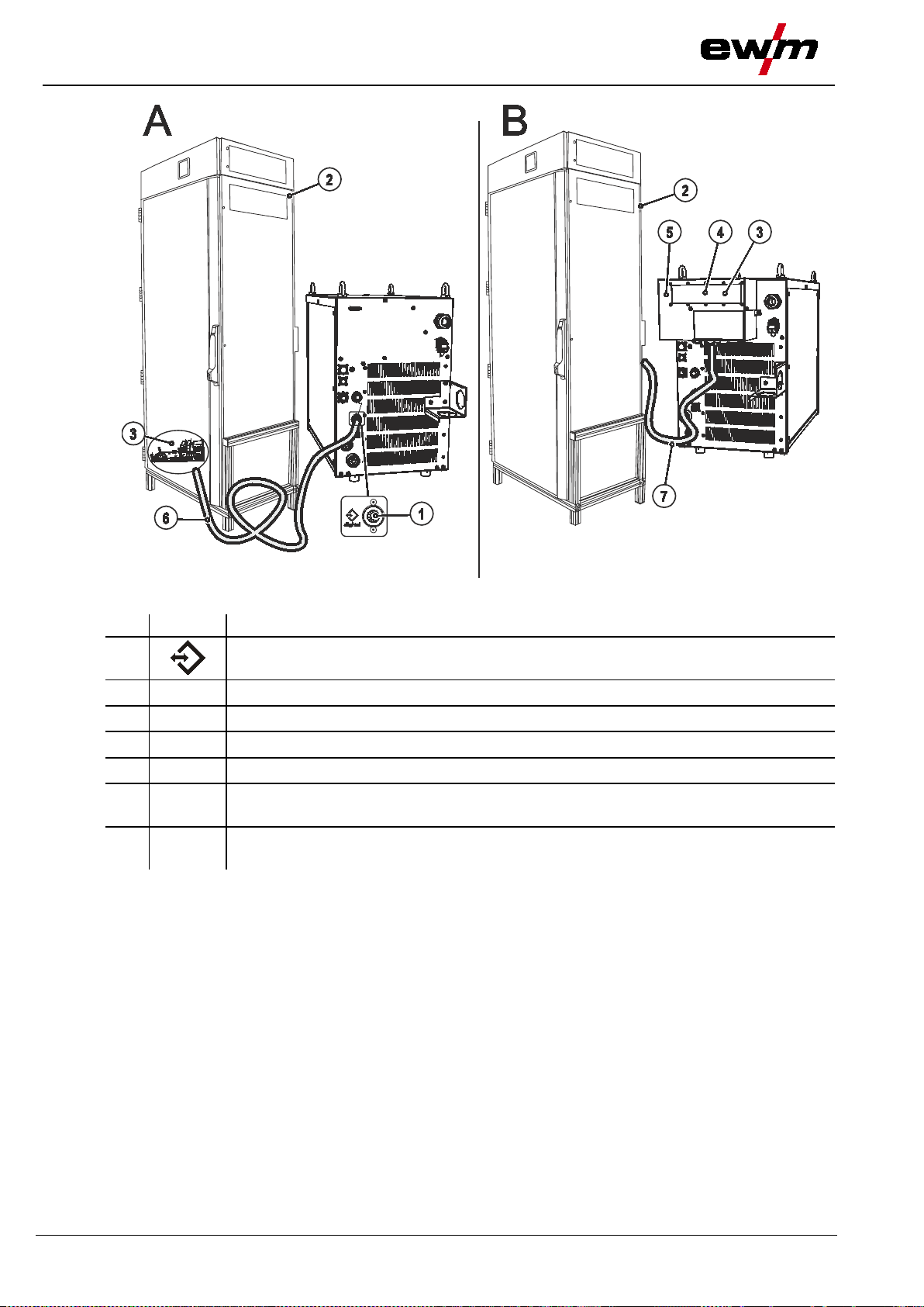
Item
Symbol
Description 0
2 Connection socket, 5-pole
5.8 Connect the cooling module t o t he power s ource
Please note the relevant documentation of the accessory components.
Connect the cooling module to the power source
1
• Insert and lock the 8-pole control lead plug on the cooling module into the 8-pole connection socket on
the welding machine.
• Insert and lock the 5-pole supply plug on the cooling module into the 5-pole connection socket on the
welding machine.
099-005366-EW501
8-pole connection socket
Cooling unit control lead
Cooling unit voltage supply
Figure 5-5
31
Design and function
Mains connection
31.07.2014
DANGER
Hazard caused by improper mains connection!
protection class 1.
NOTE
The machine may be connected to:
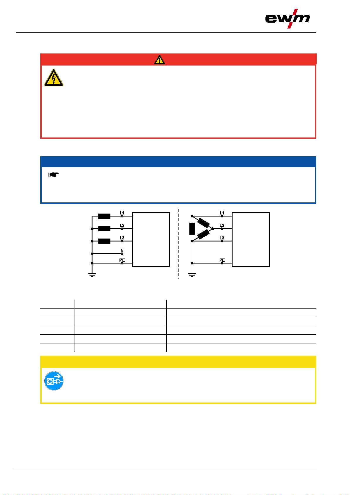
e.g. the outer conductor
Item
Designation
Colour code
L1
Outer conductor 1
brown
L2
Outer conductor 2
black
L3
Outer conductor 3
grey
N
Neutral conductor
blue
PE
Protective conductor
green-yellow
CAUTION
• For mains fuse protection, please refer to the “Technical data” chapter!
5.9 Mains connection
An improper mains connection can cause injuries or damage property!
• Only use machine with a plug socket that has a correctly fitted protective conductor.
• If a mains plug must be fitted, this may only be carried out by an electrician in accordance
with the relevant national provisions or regulations!
• Mains plug, socket and lead must be checked regularly by an electrician!
• When operating the generator always ensure it is earthed as stated in the operating
instructions. The resulting network has to be suitable for operating devices according to
5.9.1 Mains configuration
• a three-phase system with four conductors and an earthed neutral conductor
• a three-phase system with three conductors of which any one can be earthed,
Figure 5-6
Legend
Operating voltage - mains voltage!
The operating voltage shown on the rating plate must be consistent with the ma ins
voltage, in order to avoid damage to the machine!
• Insert mains plug of the switched-off machine into the appropriate socket.
32
099-005366-EW501

31.07.2014
NOTE
shielding cored wire) are welded using ne gative polarity.
• Observe the information from the electrode manufacturer!
Item
Symbol
Description 0
Intermediate hose package strain relief
7-pole connection socket (digital)
Wire feed unit connection
12-pole connection socket (analogue)
welding torch and the power source
Connection socket, “+” welding current
• MIG/MAG welding:
Welding current to wire feed/torch
Connection socket, “-” welding current
• MIG/MAG cored wire welding:
Welding current to wire feed/torch
5.10 Intermediate hose package connection
Note the polarity of the welding curren t!
Some wire electrodes (e.g. self-
In this case, the welding current lead should be connected to the "-" welding current
socket, and the workpiece lead should b e connected to the "+" welding current socket.
Design and function
Intermediate hose package connec t ion
1
2
3
Connection socket for analogue control signals (collision protection, etc. ) between the
4
5
• Insert the end of the tube package through the intermediate tube package strain relief and lock by
turning to the right. If applicable, follow the instructions from the third party manufacturer of the strain
relief.
• Insert the welding current plug of the wire feeder unit in the "+" welding current connection socket and
lock by turning to the right.
• Insert the wire feed control lead plug into the 7-pole connection socket (digital) and lock.
• Insert the analogue control signal cable plug into the 12-pole (analogue) connection socket and lock
by turning to the right.
099-005366-EW501
Figure 5-7
33
Design and function
Matching the cable resistance
31.07.2014
2
3
4
1
l
0
50mm
l
0
A
RINT X12
BUSINT X11
1 x
n x
l
0
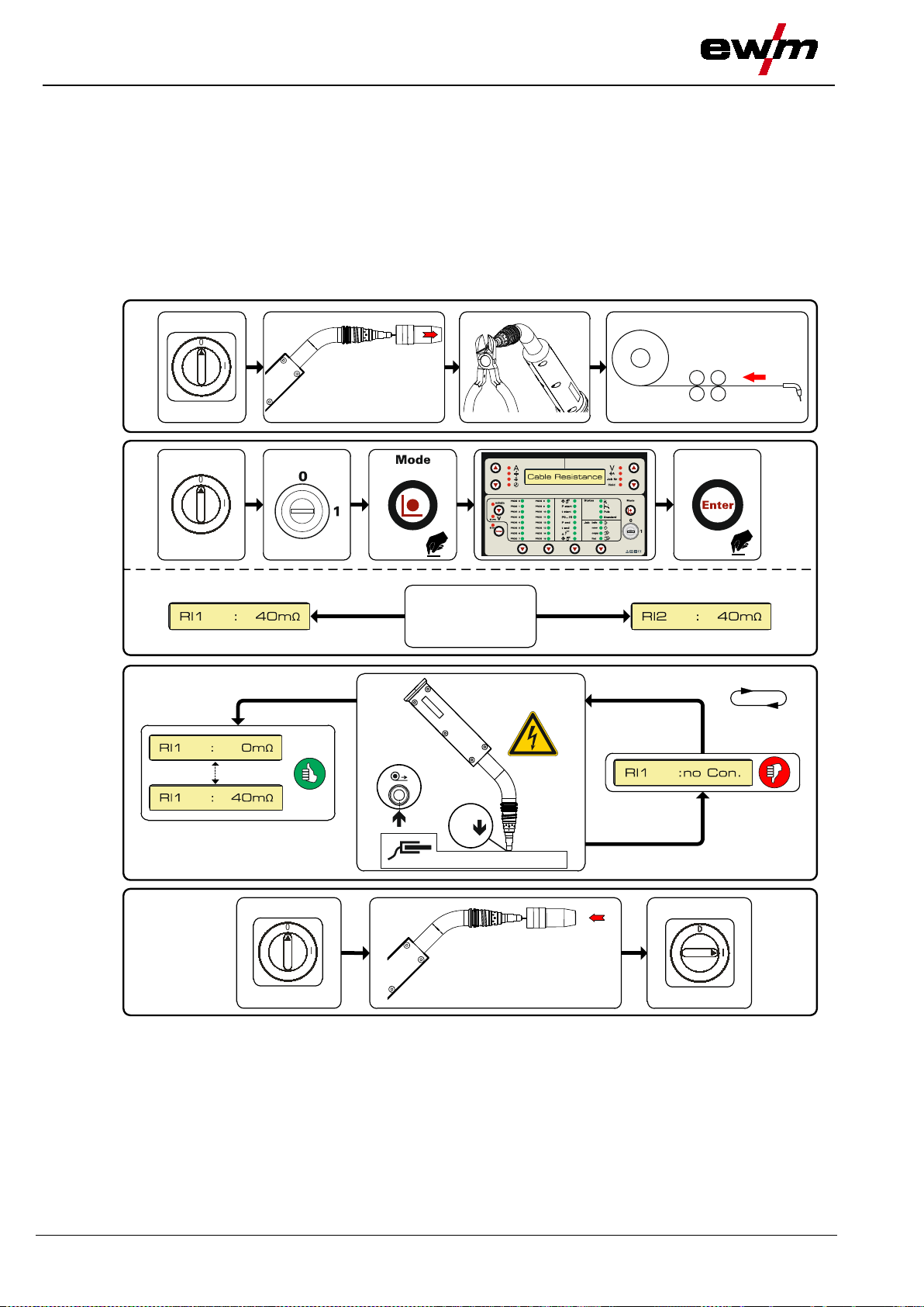
5.11 Matching the cable resistance
The resistance value of cables can either be set directly or it can be matched using the power source.
The factory setting of the power sources is 8 m-ohm. This value correponds to a 5 m earth cable, a 1.5 m
intermediate hose package and a 3 m water-cooled welding torch. With other hose package lengths, it is
necessary to carry out a +/- voltage correction to optimise welding properties. The voltage correction
value can be set close to zero by means of re-matching the cable resistance. It is recommended to match
the electric cable resistance after replacing accessories such as torches or intermediate hose packages.
In case a second wire feeder is used the (rL2) parameter has to be adjusted. For all other configurations it
is sufficient to match the (rL1) parameter.
Figure 5-8
34
099-005366-EW501

tance
31.07.2014
1 Preparation
• Switch off the welding mac hine.
• Unscrew the gas nozzle of the welding torch.
• Cut off the welding wire to be flush with the contact tip.
• Retract the welding wire a bit (approx. 50 mm) on the wire feeder. Now there should be no more
welding wire in the contact tip.
2 Configuration
• Switch on the welding machine
• At the machine control, turn the key switch to the "1" position.
• Press the "Mode" push-button until the "Cable Resistance" parameter is shown on the machine control
display.
• Confirm the parameter by the" Enter " push-button.
• In case of welding systems with a second power circuit – if two wire feeders are to be operated from a
single power source, for example – a second alignment with parameter Rl2 must be performed. To do
so, switch the wire feeder using the appropriate interface.
3 Alignment/measurement
• Place the welding torch contact tip on a cleansed part of the workpiece with light pressure and press
the inching button at the torch or wire feeder for approx. 2 seconds; this function can also be selected
via the interface. Short-circuit current flows briefly, which is used to determine and display the cable
resistance. The value can be between 0 mΩ and 40 mΩ. The new value is immediately saved without
requiring any further confirmati on. If "no Con." is shown on the display, measurement failed. The
measurement must be repeated.
4 Restoring welding standby mode
• Switch off the welding machine.
• Screw the gas nozzle onto the welding torch.
• Switch on the welding machine
• Insert the welding wire.
Design and function
Matching the cable resis
099-005366-EW501
35

Design and function
Connection for workpiece lead
31.07.2014
NOTE
shielding cored wire) are welded using ne gative polarity.
• Observe the information from the electrode manufacturer!
Item
Symbol
Description 0
Connection socket, "+" welding current
• MIG/MAG cored wire welding:
Workpiece connection
"-" welding current connection socket
• MIG/MAG welding:
Workpiece connection
5.12 Connection for workpie c e l ead
Note the polarity of the welding curren t!
Some wire electrodes (e.g. self-
In this case, the welding current lead should be connected to the "-" welding current
socket, and the workpiece lead should b e connected to the "+" welding current socket.
1
2
• Insert the plug on the workpiece lead into the "-" welding current connection socket and lock.
36
Figure 5-9
099-005366-EW501

Design and function
31.07.2014
WARNING
• Avoid heating the shielding gas cylinder!
CAUTION
Faults in the shielding gas supply.
• All shielding gas connections must be gas tight.
NOTE
Before connecting the pressure regulator to the gas cylinder, open the cylinder valve
briefly to expel any dirt.
5.13 Shielding gas supply (shie lding gas cylinder for welding machi ne )
5.13.1 Connecting the shielding gas supply
Incorrect handling of shielding gas cylinders!
Incorrect handling of shielding gas cylinders can result in serious and even fatal injury.
• Observe the instructions from the gas manufacturer and in any relevant regulations
concerning the use of compressed air!
• Place shielding gas cylinders in the holders provided for them and secure with fixing
devices.
An unhindered shielding gas supply fro m th e shielding gas cylinder to the welding
torch is a fundamental requirement fo r optimum welding results. In addition, a blocked
shielding gas supply may resul t in the welding torch being destroyed.
• Always re-fit the yellow protective cap when not using the shielding gas connection.
Shielding gas supply (shielding gas cylinder for welding machine)
099-005366-EW501
37

Design and function
Shielding gas supply (shielding gas cylinder for welding machine)
31.07.2014
Item
Symbol
Description 0
Pressure regulator
Shielding gas cylinder
3
Welding process
Recommended shielding gas quantity
MAG welding
Wire diameter x 11.5 = l/min
MIG brazing
Wire diameter x 11.5 = l/min
MIG welding (aluminium)
Wire diameter x 13.5 = l/min (100 % argon)
TIG
Gas nozzle diameter in mm corresponds to l/min gas throughput
Shielding gas
Factor
75% Ar/25% He
1.14
50% Ar/50% He
1.35
25% Ar/75% He
1.75
100% He
3.16
NOTE
• Adjust the shielding gas quantity to suit the welding task!
1
2
Output side of the pressure regulator
4
Cylinder valve
• Place the shielding gas cylinder in the cylinder holder and secure it from tipping over using the
securing chain!
• Before connecting the pressure regulator to the gas cylinder, open the cylinder valve briefly to blow out
any dirt.
• Mount the pressure regulator on the gas cylinder valve.
• Screw gas hose connection crown nut onto the output side of the pressure regulator.
• Screw the gas hose connection nipple onto the G¼" connection nipple.
• Tighten gas hose on pressure regulator to be gas tight.
• Fit the gas hose and G1/4" crown nut onto the relevant connection on the welding machine, and fit the
wire feed unit (if present on this version).
5.13.2 Setting instructions
Figure 5-10
Helium-rich gas mixtures require a higher gas volume!
The table below can be used to correct the gas volume calculated where necessary:
Incorrect shielding gas setting!
If the shielding gas setting is too low or too high, this can introduce air to the weld p o o l
and may cause pores to form.
38
099-005366-EW501

Design and function
31.07.2014
CAUTION
machine is switched off.
• Accessory components are detected automatically after the power source is switched on.
NOTE
Only one variant can ever be operated at any one time.
5.14 Interfaces
5.14.1 Connecting the RINT X11 robot interface/BUSINT X11 industrial bus interface
Damage due to the use of non-genuine parts!
The manufacturer's warranty becomes void if non-genuine parts are used!
• Only use system components and options (power sources, welding torches, electrode
holders, remote controls, spare parts and replacement parts, etc.) from our range of
products!
• Only insert and lock accessory components into the relevant connection socket when the
Damage due to incorrect connection!
Accessory components and the power source itself can be damaged by incorrect
connection!
• Only insert and lock accessory components into the relevant connection socket when the
machine is switched off.
• Comprehensive descriptions can be found in the operating instructions for the relevant
accessory components.
Interfaces
The interfaces can be operated directly on the power source in a separate interface casing or externally,
e.g. in a robot control cabinet or via a data cable.
5.14.2 RINT X12 robot interface
The standard digital interface for mechanised applications
(optional, retrofitting on the machine or external fitting by the customer)
Functions and signals:
• Digital inputs: start/stop, operating modes, JOB and program selection, inching, gas test
• Analogue inputs: control voltages, e.g. for welding performance, welding current, etc.
• Relay outputs: process signal, ready for welding, system composite fault, etc.
5.14.3 BUSINT X11 industrial bus interface
The solution for integration into mechanised production lines, with for example
• Profibus
• CAN-Open, CAN DeviceNet
• Interbus systems with copper and optical fibre connection (FSMA/Rugged Line)
099-005366-EW501
39
Design and function
Interfaces
31.07.2014
Item
Symbol
Description 0
For connecting digital accessory components
Robot interface, Tetrix / Phoenix / alpha Q, RINT X12
Industrial bus interface, Tetrix / Phoenix / alpha Q, BUSINT X11
5
Connection between switching cabinet and power source
Connection lead
Connection between interface casing and switching cabinet
1
2
3
4
6
7
7-pole connection socket (digital)
Switching cabinet
Interface casing
Connection cable, 7-pole
Figure 5-11
40
099-005366-EW501
Design and function
31.07.2014
Item
Symbol
Description 0
PC interface, serial (D-Sub connection socket, 9-pole)
2
3
RC300 tablet PC
USB connection
6
CAUTION
Equipment damage or faults may occur if the PC is connected incorrectly!
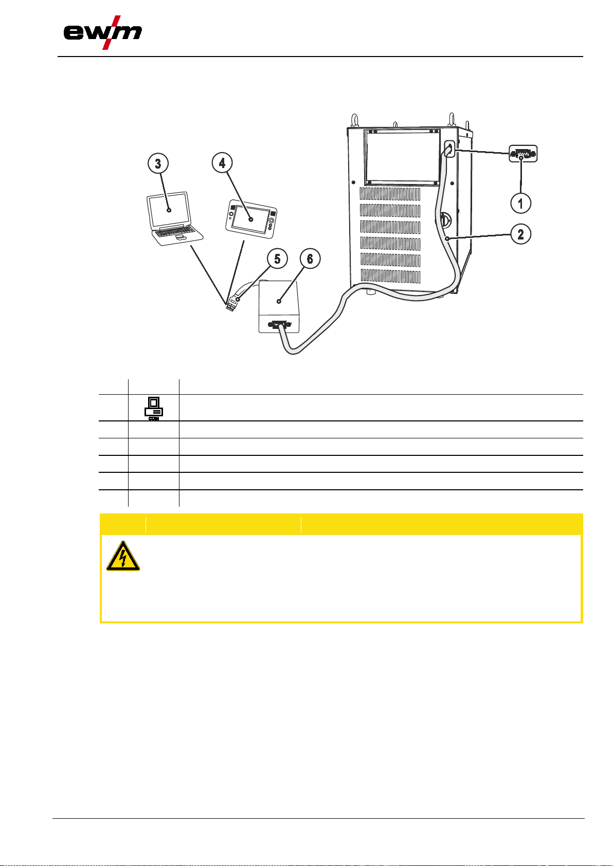
5.14.4 Connecting the PC 300.net welding parameterisation software
Create all welding parameters quickly on the PC and easily transfer them to one or more welding
machines (accessories, set consisting of software, interface, connection leads)
Interfaces
1
Connection cable, 9-pole, serial
Windows PC
4
5
SECINT X10 USB
Not using the SECINT X10USB interface results in equipment damage or faults in signal
transmission. The PC may be destroyed due to hi gh frequency ignition pulses.
• Interface SECINT X10USB must be connected between the PC and the welding machine!
• The connection must only be made using the cables supplied (do not use any additional
extension cables)!
Figure 5-12
099-005366-EW501
41

Design and function
Interfaces
31.07.2014
Item
Symbol
Description 0
For connecting digital accessory components
Windows PC
RC300 tablet PC
4
5
Connection cable, 7-pole
Connection between switching cabinet and power source
CAUTION
Equipment damage or faults may occur if the PC is connected incorrectly!
extension cables)!
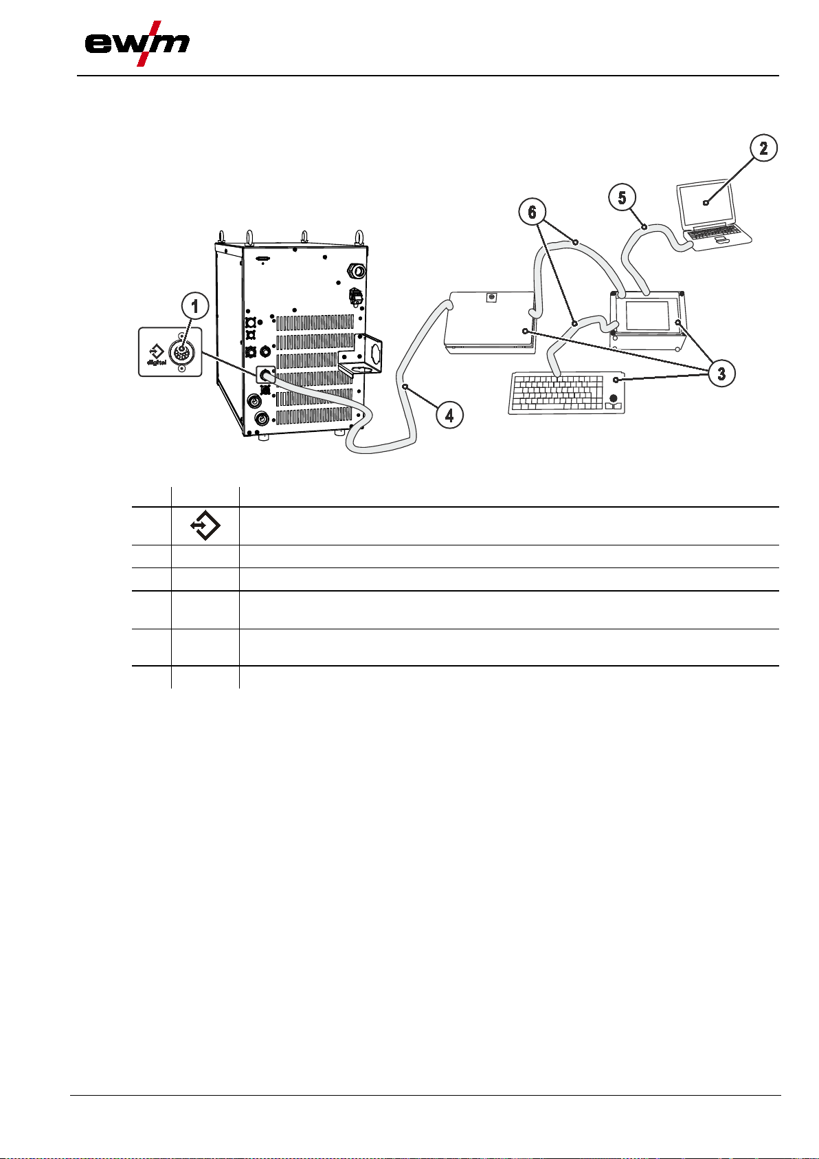
5.14.5 Connecting the Q-DOC 9000 welding data documentation software
(Accessories: Set consisting of software, interface, connection leads)
The ideal tool for welding data documentation of, for example:
welding voltage and current, wire speed and motor current.
1
Figure 5-13
7-pole connection socket (digital)
2
3
SECINT X10 USB
Connection cable, 9-pole, serial
6
PCINT X10
7
Not using the SECINT X10USB interface results in equipment damage or faults in signal
transmission. The PC may be destroyed due to hi gh frequency ignition pulses.
• Interface SECINT X10USB must be conn ec ted betw een the PC and the welding machine!
• The connection must only be made using the cables supplied (do not use any additional
42
099-005366-EW501
Design and function
31.07.2014
Item
Symbol
Description 0
For connecting digital accessory components
WELDQAS welding data monitoring and docum entation system
Connection cable, 7-pole
Connection between switching cabinet and power source
cables
5.14.6 Connecting the WELDQAS welding data monitoring and documentation system
Network-compatible welding data monitoring and documentation system for digital power sources.
Interfaces
1
2
3
4
5
6
7-pole connection socket (digital)
Windows PC
Integration option of WELDQAS into existing network systems via network
Connection cable included as standard with WELDQAS
Figure 5-14
099-005366-EW501
43

Design and function
Interfaces
31.07.2014
CAUTION
• Use shielded control leads only.
WARNING
No function of the external interr u p t equipment (emergency stop switch)!
• Disconnect jumper 1 on PCB T320/1 (Tetrix / forceTig) or M320/1 (Phoenix / alpha Q)!
5.14.7 Automation interface
The welding power sources feature a very high safety standard.
This safety standard is also maintained when peripheral equipment is connected for mechanised welding,
if this peripheral equipment meets the same criteria, particularly with regard to isolation from the mains
supply.
This is guaranteed by the use of transformers conforming to VDE 0551.
The welding machines are equipped for mechanised operation as standard.
For the simplest possible mechanised applications, control inputs and galvanically isolated relay contacts
are available on the interface for mechanised welding.
Equipment damage due to unshielded contro l leads!
Unshielded control leads can cause damage to the power source and accessory
components.
Figure 5-15
If the emergency stop circuit has been realised using an external interrupt equipment
via the interface for automated welding, the machine must be configured for this setup.
If this is not observed, the power source will ignore the external interrupt equipment
and will not shut down!
44
099-005366-EW501

Design and function
31.07.2014
Pin
Input/output
Designation
Note
Cable screen connection
B
Output
REGaus
15 V = no welding current
E/R
Not-Aus
contact!
F
Output
0V
I>0 to the user
+U
act
J
K
Output
SYN_A1
Seam tracking synchronising signal
Start/stop
Switch to potential-free
Power supply
N
Power supply
S
Output
0V
+I
act
box, collision switch
V
box, collision switch
19-pole connection assignment for mechanised welding interface (X4):
Interfaces
A Output PE
C Input Gasdüsensensor 1
D Output IGR0
Current flowing signal (I>0)
0 V = welding current
Input
Open = welding current switched off
G/P Output IGR0
Power relay contact,
H Output Uist
Output DVist
Maximum load 100 mA
Not isolated!
Make sure that jumper 1 on PCB
M320/1 of the welding machine is
open!
Connection with potential-free
Potential-free, +-15 V/100 mA
10 V = 100 V welding voltage
L Input STA/STP
M Output +15V
Output -15V
T Output Iist
U Output Not-Aus 1
Output Not-Aus 2
Contact at M
+15 V, max. 75 mA
-15 V, max. 25 mA
10 V = 1000 A welding current
e.g. emergency stop for shutdown
e.g. emergency stop for shutdown
099-005366-EW501
45

Design and function
Interfaces
31.07.2014
Pin
Signalshape
Circuit diagram signal
name
Function
A NC B NC
Emergency s top for higher level shut-down of the
Contact open = welding current switched off
D NC E Gasdüsensensor 1
F
NC G NC H NC J NC
K NC M NC
12-pole connection assignments for mechanised we lding interface (X2):
C/L Input Not-Aus
power source.
To use this function, jumper 1 must be unplugged on
PCB M320/1 in the welding machine.
5.14.8 Sensor Voltage
Outside the welding process , there is a voltage of approx. 12 V on the welding torch electrode. If the
electrode comes into contact with the workpiece or the molten pool, the short-circuit produced means that
when using the relevant interface (BUSINT X11/RINT X12), the resultant signal can be used for various
functions (e.g. workpiece search).
46
099-005366-EW501

Design and function
31.07.2014
Before welding
During welding
After welding
value
value
value
Welding current
Material thickness
Wire speed
Welding voltage
Motor current
JOB no.
Operating time
5.15 Protecting welding para m e ters from unauthorised access
To protect against unauthorised or unintentional adjustment of the welding parameters on the machine,
the control input can be locked with the aid of a key switch.
In key switch position 1 all functions and parameters can be set without restriction.
In key switch position 0 the following functions and parameters cannot be changed:
5.15.1 Welding data display
To the left and right of the LCD display on the control there are 2 “arrow keys” on each side for selecting
the welding parameter to be displayed. The button is used to scroll through the parameters from the
bottom upwards and the button is used to scroll downwards from the top.
As soon as changes have been made to the settings after welding (display on hold values) the display
switches back to the nominal values.
Protecting welding parameters from unauthorised access
Figure 5-16
Parameter
Nominal value Actual value Nominal
Hold
Nominal
099-005366-EW501
47

Design and function
Definition of MIG/MAG welding tasks
31.07.2014
NOTE
The parameters and
laptop and the PHOENIX PCM 300 welding param eter software.
5.16 Definition of MIG/MAG welding tasks
The user defines the welding tasks using job numbers.
Each job number stores all the parameters relating to the welding task.
For the most commonly used applications, 128 pre-programmed JOBs (welding tasks) are stored in the
machine control with the relevant parameters.
On the control panel, the user can either load an existing job, load an existing job and change it, or define
a completely new job.
The welding task or job is defined usin g th e following parameters:
Basic parameters
The job number is defined using four basic welding parameters:
Welding process, material type, wire diameter and gas type.
According to the pre-programmed jobs, the typical or frequently used gas types and wire diameters for
the material are suggested automatically depending on the material type selected. It is impossible to
select inappropriate combinations for welding.
Program sequence
Other welding parameters, such as parameters for the start program, secondary program or end program
and the gas pre-flow time, wire creep, slope times, wire burn-back (and many more) are preset for a
variety of applications, but can be modified where required. On the control panel, the most important
welding parameters are displayed directly and can be modified where required.
Program or control voltage (operating point)
The operating point can either be set using up to 15 (PROG 1 to PROG 15) freely definable programs or
using control voltages (PROG 0) via the robot interface (RINTX12 / BUSINTX11).
• The wire speed, voltage correction and dynamics are stored in each program. These program
parameters can be specified on the control panel. The program number is selected by the robot
control.
• In control voltage mode, there is a control voltage (0 V to 10 V) available on the robot interface for
each parameter (wire speed, voltage correction and dynamics).
The digital system calculates the required process parameters, such as the welding current, welding
voltage and pulse current according to the operating point specified.
Operating mode
Non-latched or non-latched special (start current, main current and end program)
Welding type
Pulse or standard welding
functions described here can also be programmed using a PC or
48
099-005366-EW501

31.07.2014
element
Select "Job new"
1 x
Select "Welding process"
Select "Welding process"
Verf. : MIG
1 x
1 x
Select "Wire diameter"
Draht : xxxxxx
1 x
Select "Gas type"
Gas-Art : xxxxxx
1 x
Select "Job number"
Jobs 129 to 256 (free memory space)
Job-Nr. : xxx
1 x
Save job number
Save selected job number in the free memory
Wait
NOTE
The job number is selected and changed by the robot control via robot interface
RINTX11 or BUSINTX12.
5.16.1 Welding task sel ect ion
5.16.1.1 Selecting or de fining a new job Option 1: Select job from existing job reference list
To do this, the job overview (see Appendix 2) is used as a reference for determining the welding task.
It is also possible to use the "Job list" menu option on the M3.40 power source control to determine the
relevant job number according to the basic parameters (see Appendix 1: "Job organisation function
sequence").
Defining a new job
Operating
Action Result Display (example)
X x
Design and function
Definition of MIG/MAG welding tasks
Verf. : MIG
The signal light displays the selection.
Verf. : MIG
n x
n x
n x
n x
n x
Select "Material type" Material: xxxxx
Select "Material type" Material: xxxxx
Select "Wire diameter" Draht : xxxxxx
Select "Gas type" Gas-Art : xxxxxx
Select "Job number" Job-Nr. : xxx
Search for job number for selected welding task:
099-005366-EW501
49
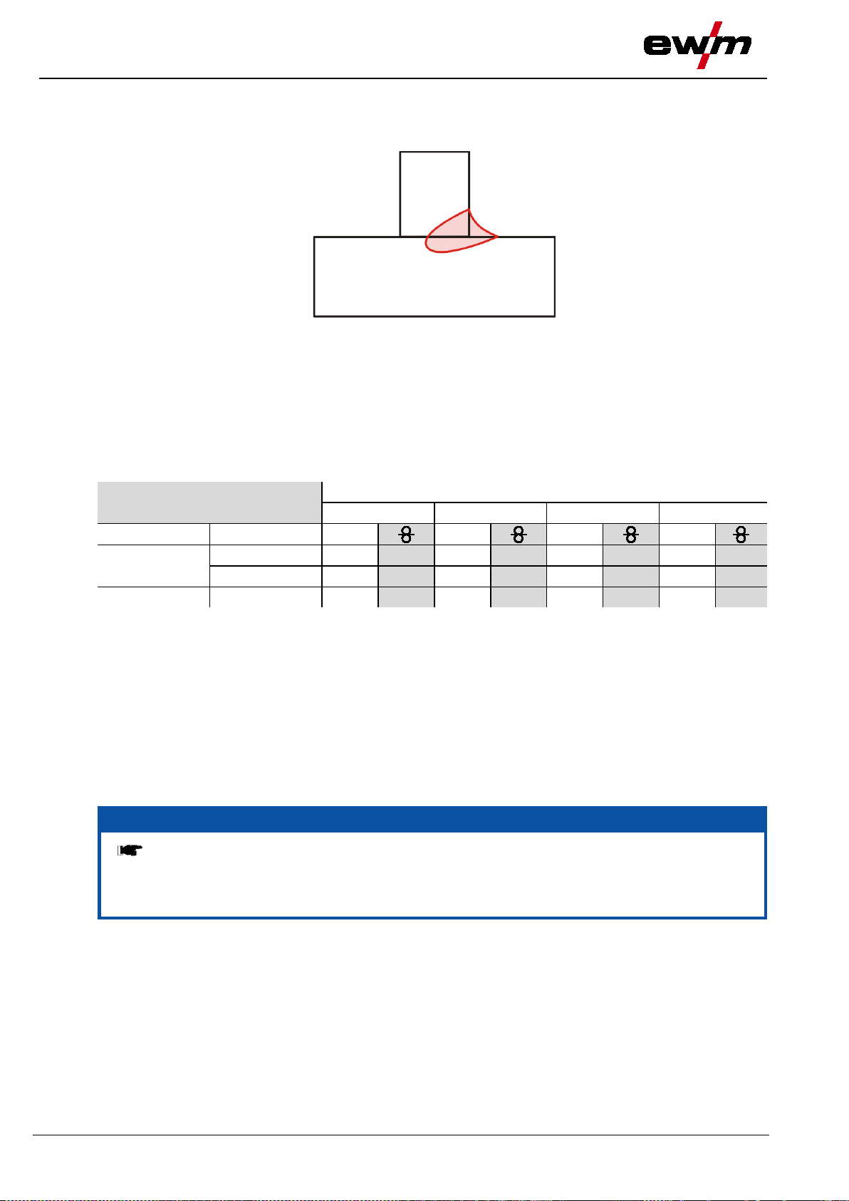
Design and function
Definition of MIG/MAG welding tasks
31.07.2014
forceArc welding from:
Wire Ø (mm)
0.8 1 1.2
1.6
Material
Gas
JOB
JOB
JOB
JOB
Ar 91–99%
190
17.0
254
12.0
255
9.5
256
7.0
Ar 80–90%
189
17.0
179
12.0
180
9.5
181
6.0
CrNi
Ar 91–99%
- - 251
12.0
252
12.0
253
6.0
NOTE
hose packages. Avoid loops!
5.16.2 forceArc / forceArc puls
Heat-reduced, directionally stable and powerful arc with deep penetration for the upper power range.
• Smaller included angle due to deep penetration and directionally stable arc
• Excellent root and sidewall fusion
• Secure welding also with very long stick-outs
• Reduced undercuts
• Un-, low- and high-alloyed steels as well as high-tensile fine-grained building steels
• Manual and automated applications
Figure 5-17
Steel
You can make use of these properties after selecting the forceArc process (see the "Selecting a
MIG/MAG welding task" chapter).
As with pulse arc welding, it is important to make sure of a good welding current connection.
• Keep welding current cables as short as possible and ensure that cable cross-sections are adequate!
• Fully unroll welding current cables, torche hose packages and, if applicabl e, inter m edi ate hose
packages. Avoid loops!
• Use welding torches, preferably water-cooled, that are suitable for the higher power range.
• Use welding wire with adequate copper coating when welding steel. The wire spool should have layer
spooling.
Unstable arc!
Welding current cables that are not fully unrolled can cause faults in the arc (flickering).
• Fully unroll welding current cables, torch hose packages and, if applicable, intermediate
50
099-005366-EW501

31.07.2014
coldArc welding to:
Wire Ø (mm)
0.8
0.9 1 1.2
1.6
CrNi
Ar 91–99%
- - - - 51
7.0
52
6.0 - -
AlMg
Ar 100%
- - - - 55
8.0
56
8.0 - -
ALSi
Ar 100%
- - - - 59
8.0
60
6.0 - -
AL99
Ar 100%
- - - - 63
8.0
64
6.0 - -
Ar 91–99%
- - - - - - - - - - Ar 80–90%
191
7.0
192
6.0
193
6.0
194
5.0
195
5.0
CO2
182
7.0
183
6.0
184
6.0
185
5.0
186
5.0
Wire Ø (mm)
0.6
0.8
0.9 1 1.2
1.6
CuSi
Ar 100%
- - 66
10.0 - -
67
8.0
68
6.0
69
6.0
CuAl
Ar 100%
- - 70
7.0 - -
71
6.0
72
6.0
73
7.0
AlSi
Ar 100%
- - 196
8.0 - -
197
8.0
198
8.0
199
8.0
Zn
Ar 100%
- - 200
6.0 - -
201
6.0
202
6.0
203
6.0
NOTE
This function can only be enabled wi th th e PC300.NET software.
• (See operating instructions for the software)
5.16.3 coldArc / coldArc puls
Heat-reduced, low-spatter short arc for welding and brazing of thin metal sheets with low distortion and
for root welding with excellent gap bridging properties.
After selecting the coldArc process (see chapter “Selecting a MIG/MAG welding task”) the following
properties are available:
• Less distortion and reduced discolouration thanks to minimised heat input
• Considerably reduced spatter thanks to virtually power-free material transfer
• Easy welding of root passes in all panel thicknesses and in all positions
• Perfect gap bridging even with inconsistent gap widths
• Unalloyed, low-alloy and high-alloy steels and also dissimilar joints of even the thinnest metal sheets
• Brazing of CrNi sheets with CuAl8/AlBz8
• Brazing and welding of coated metal sheets, e.g. with CuSi, AlSi and Zn
• Manual and automated applications
Figure 5-18
Design and function
Definition of MIG/MAG welding tasks
Material Gas JOB
JOB
JOB
JOB
JOB
Steel
coldArc brazing to:
Material Gas JOB
JOB
JOB
JOB
JOB
JOB
You can make use of these properties after selecting the coldArc process (see the "Selecting a MIG/MAG
welding task" chapter).
With coldArc welding, it is importa n t to ensure good quality wire feeding because of the welding
filler materials being used!
• Equip the welding torch and torch hose package to suit the task! (See the "Connecting the welding
torch" chapter and the operating instructions for the welding torch.)
099-005366-EW501
51
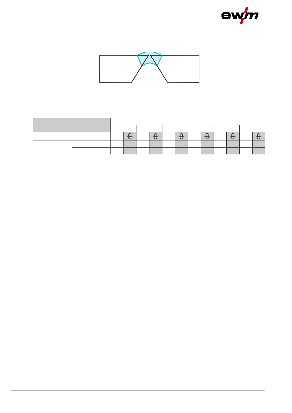
Design and function
Definition of MIG/MAG welding tasks
31.07.2014
pipeSolution welding to:
Wire Ø (mm)
0.6
0.8
0.9 1 1.2
1.6
Material
Gas
JOB
JOB
JOB
JOB
JOB
JOB
CO2
x x x x x x 171
6.0
172
5.0 x x
Ar 80–90%
x x x x x x 173
6.0
174
5.0 x x
5.16.4 pipeSolution
Powerful arc for rapid, secure welding with and without gap in all positions.
• Root welding for metal sheets and pipes in all positions
• Unalloyed and low-alloy steels as well as high-tensile fine-grained steels
• Manual and automated applications
Steel
Figure 5-19
52
099-005366-EW501

31.07.2014
NOTE
This parameter can be changed over dur ing the welding process.
NOTE
The operating point can either be spe cified using up to 15 freely definable programs
(PROG 1 to PROG 15) or an operating point can b e set using control voltages (PROG 0)
via the robot interface (RINTX11 / BUSINTX10).
Operating
element
Action
Result
Display
Select "Wire speed"
Select "Voltage correction"
P1 U2 : + x.x V
5.16.4.1 Operating mode
This parameter setting is specified by the robot control via the RINTX12 or BUSINTX11 robot interface
(see documentation in the relevant interface description).
The selected parameter is displayed on the status displays on the control panel.
5.16.5 Welding type
This parameter setting is specified by the robot control via the RINTX12 or BUSINTX11 robot interface
(see documentation in the relevant interface description).
5.16.5.1 Program or control voltage mode
The selected parameter is displayed on the status displays on the control panel.
Different welding tasks or positions on a workpiece demand various welding outputs (operating points) or
welding programs.
For each program, the
• Wire speed
• Correction of the arc length and the
• Dynamics / choke effect
can be set separately.
15 different programs (PROG 1 to PROG 15) can be defined. It is possible to switch between these
programs during the welding process.
The parameters for the relevant program are selected on the control panel.
Design and function
Definition of MIG/MAG welding tasks
X x
1 x
n x
1 x
n x
1 x
Select "Program number"
The signal light displays the selection.
PROG 1 to PROG 15 are available.
Select "Wire speed"
The signal light displays the selection (m/min).
Setting from 0.1 to 40.0 m/min.
The signal light displays the selection (V).
Select "Voltage correction"
Setting from -9.9 V to +9.9 V.
Press "Dynamics"
The signal light (DYN) flashes.
P1 DV2 : 2.0m/m
P1 DV2 : x.x m/m
P1 DV2 : x.x m/m
P1 U2 : + x.x V
099-005366-EW501
53

Design and function
Definition of MIG/MAG welding tasks
31.07.2014
Operating
element
Action
Result
Display
Select "Dynamics"
Graphic
Symbol
Parameter
Value
Gas pre-flows
0.0 to 20.0 sec
Start time
0.0 to 20.0 sec
Program number
P0 to P15
End time
0.0 to 20.0 sec
Wire burn-back
2 to 500
Gas post-flow time
0.0 to 20.0 sec
Control voltage operation
This parameter setting is specified by the robot control via the RINTX12 or BUSINTX11 robot interface
(see documentation in the relevant interface description).
Signal light "PROG 0" lights up on control panel.
5.16.5.2 Program sequence
Certain materials, such as aluminium, require special functions in order to be able to weld them safely
and at high quality. T he no n-latched special operating mode is used here with the following programs:
The following parameters can be selected and changed on the control panel:
n x
Setting from -40 to +40.
Figure 5-20
Parameter changes are made either using the "Welding parameter " rotary dial or the
buttons.
The program P
corresponds to one of the up to 15 freely definable programs. The times for parameters
A
tS1 and tSe (soft wire transfer) are factory-set.
The complete list of parameters can be found in chapter:
MIG/MAG program sequence ("Program steps" mode).
The signal lights display the current progress in the function sequence throughout the welding process.
Ignition program
• Wire speed
WFstart 0 % to 200 % or
Ustart -9.9 V to +9.9 V
• Voltage correction
Change with button
End program
• Wire speed
WFend 0 % to 200 % or
Uend -9.9 V to +9.9 V
• Voltage correction
Change with button
54
099-005366-EW501
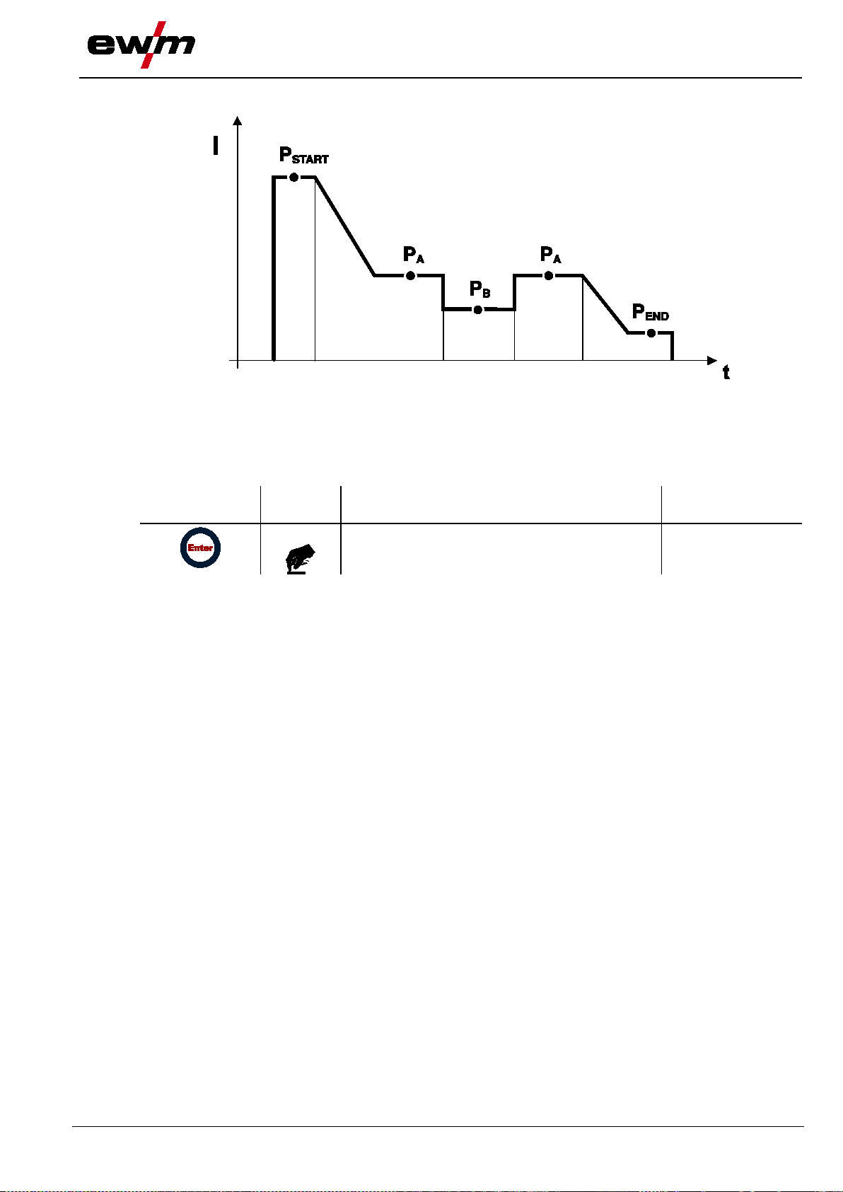
31.07.2014
element
Switch superpulses on or off
5.16.5.3 superPuls
With superpulses, there is a changeover between the main program (PA) and reduced main program (PB).
This function is used in the very thin metal sheet range, for example, to reduce the heat input in a
targeted way.
Selection on the operating panel:
Operating
Design and function
Definition of MIG/MAG welding tasks
Figure 5-21
Action Result Display
For setting the program parameters, see "MIG/MAG program sequence" ("Program steps" mode) chapter.
2 s
No change
The "SP" signal light displays the selection.
099-005366-EW501
55
Design and function
Definition of MIG/MAG welding tasks
31.07.2014
NOTE
back, etc. for numerous applications (although these can also be changed if required).
Symbol
Meaning
End of welding
I
Welding output
Non-latched
Non-latched special
t
Time
PSTART
Start program
Flat
Main program
PEND
End program
5.16.6 MIG/MAG functional sequences / operating modes
There are optimum pre-sets for welding p ar ameters such as gas pre-flow and burn
5.16.6.1 Explanation of sig n s and functions
Start of welding
Shielding gas flowing
Wire electrode is being conveyed
Wire creep
Wire burn-back
Gas pre-flows
Gas post-flows
56
099-005366-EW501

31.07.2014
Non-latched mode
Step 1
• Robot issues the start signal to the power source.
• Shielding gas is expelled (gas pre-flows).
• Wire feed motor runs at “creep speed”.
• Arc ignites after the wire electrode makes contact with the workpiece; welding current flows.
• Changeover to pre-selected wire speed (main program P
Step 2
• Robot issues the stop signal to the power source.
• WF motor stops.
• Arc is extinguished after the pre-selected wire burn-back time elapses.
• Gas post-flow time elapses.
Figure 5-22
Design and function
Definition of MIG/MAG welding tasks
).
A
099-005366-EW501
57
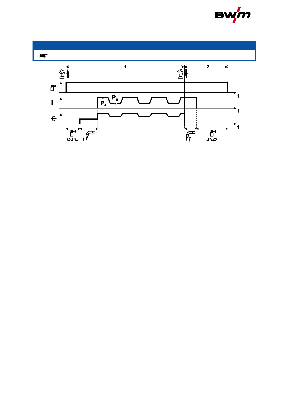
Design a
nd function
Definition of MIG/MAG welding tasks
31.07.2014
NOTE
Pulse arc welding machines only.
Non-latched operation with superpulse
Figure 5-23
Step 1
• Robot issues the start signal to the power source.
• Shielding gas is expelled (gas pre-flows).
• Wire feed motor runs at “creep speed”.
• Arc ignites after the wire electrode makes contact with the workpiece; welding current flows.
• Start the super pulse function beginning with main program P
The welding parameters switch between main program P
specified times.
Step 2
• Robot issues the stop signal to the power source.
• Super pulse function is ended.
• Wire feed motor stops.
• Arc is extinguished after the pre-selected wire burn-back time elapses.
• Gas post-flow time elapses.
:
A
and the reduced main program PB at the
A
58
099-005366-EW501
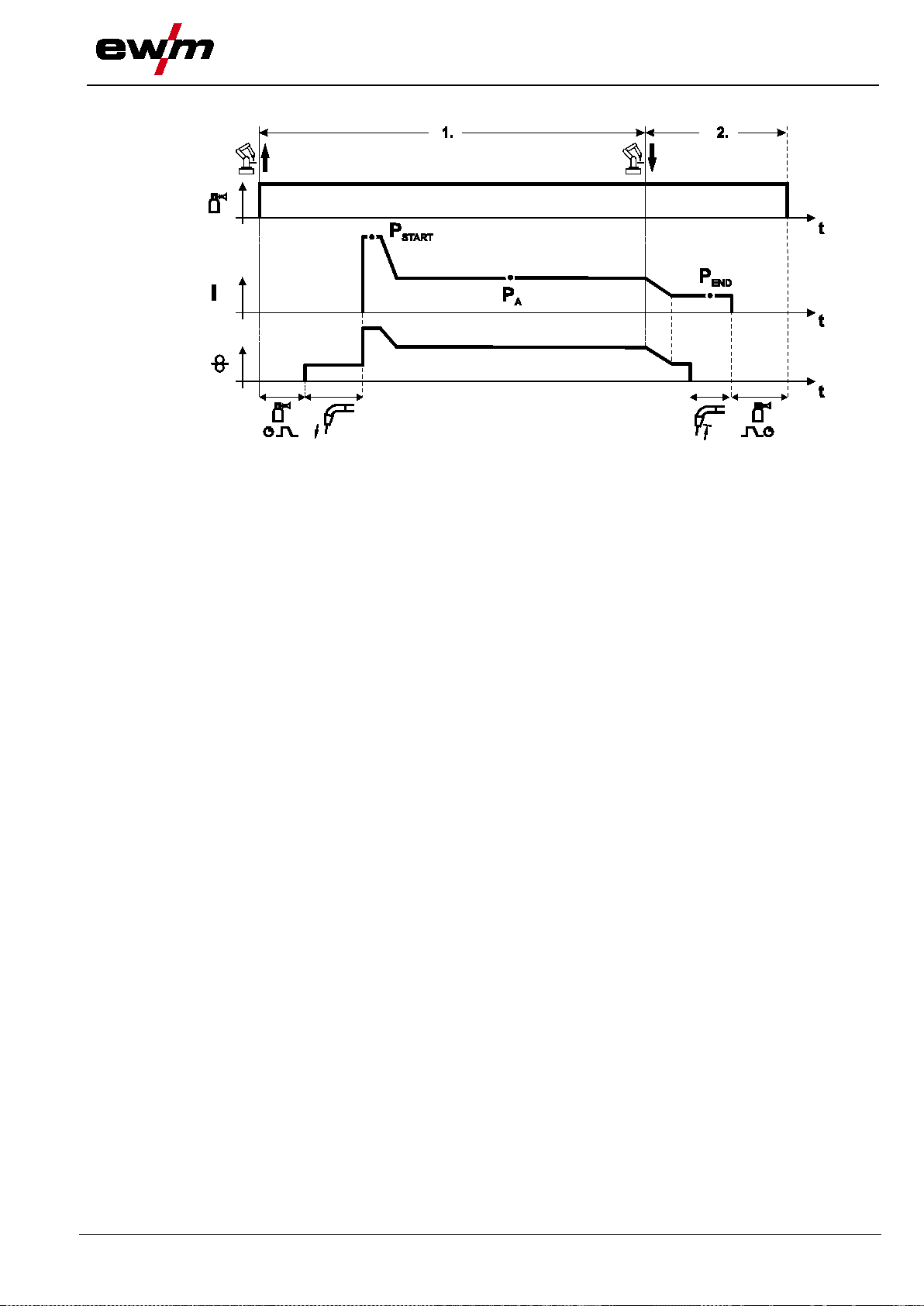
31.07.2014
Special, non-latched
Step 1
• Robot issues the start signal to the power source.
• Shielding gas is expelled (gas pre-flows)
• Wire feed motor runs at “creep speed”.
• Arc ignites after the wire electrode makes contact with the workpiece, welding current is flowing (start
program P
for the time t
START
• Slope to main program P
Step 2
• Robot issues the stop signal to the power source.
• Slope to end program P
• WF motor stops.
• Arc is extinguished after the pre-selected wire burn-back time elapses.
• Gas post-flow time elapses.
).
start
.
A
for the time t
END
Figure 5-24
.
end
Design and function
Definition of MIG/MAG welding tasks
099-005366-EW501
59

Design and function
Definition of MIG/MAG welding tasks
31.07.2014
NOTE
Pulse arc welding machines only.
Special, non-latched with superpulse
Step 1
• Robot issues the start signal to the power source.
• Shielding gas is expelled (gas pre-flows)
• Wire feed motor runs at “creep speed”.
• Arc ignites after the wire electrode makes contact with the workpiece, welding current is flowing (start
program P
for the time t
START
• Slope on main program P
• Start the super pulse function beginning with main progr am P
The welding parameters switch between main program P
specified times.
Step 2
• Robot issues the stop signal to the power source.
• Super pulse function is ended.
• Slope to end program P
• WF motor stops.
• Arc is extinguished after the pre-selected wire burn-back time elapses.
• Gas post-flow time elapses.
).
start
.
A
for the time t
END
Figure 5-25
.
end
:
A
and the reduced main program PB at the
A
60
099-005366-EW501

ion
31.07.2014
element
Adjust the selected parameter using the buttons
Machine returns to display mode
5.16.7 MIG/MAG program sequence ("Program steps" mode)
Certain materials, such as aluminium, require special functions in order to be able to weld them safely
and at high quality. The non-latched special operating mode is used here with the following programs:
• Start program P
• Main program P
• Reduced main program P
• End program P
(reduction of cool points at the start of the seam)
START
(continuous welding)
A
(targeted heat reduction)
B
(minimisation of end craters via targeted heat reduction)
END
5.16.8 Selection
Operating
Action Result Display
Select program sequence mode Program steps
1 x
Design and funct
Definition of MIG/MAG welding tasks
n x
n x
and "Down" (left)
"Up" and "Down" (right)
3 x
5.16.9 MIG/MAG overview of parameters for M3.1x
Select the parameters using the buttons "Up"
Figure 5-26
099-005366-EW501
61

Design and function
Definition of MIG/MAG welding tasks
31.07.2014
Display
Meaning / explanation
Setting range
GASstr
Gas pre-flow time
0.0s to 0.9s
RUECK
Wire burn-back length
2 to 500
GASend:
Gas post-flow time
0.0s to 20s
Proc.Sp.
Process speed to determine the a-measurement
10cm to 200cm
DVstart
Wire speed
1% to 200%
Ustart
Arc length correction
-9.9V to +9.9V
tstart
Duration
0.0s to 20.0s
tS1
Slope duration from P
START
to PA
0.0s to 20.0s
t2
Duration (spot time and superpulse)
0.01s to 20.0s
tS2
Slope duration from PA to PB
0.00s to 20.0s
DV3
Wire speed
1% to 200%
U3
Arc length correction
-9.9V to +9.9V
t3
Duration
0.01s to 20.0s
tS3
Slope duration from PB to PA
0.00s to 20.0s
tSe
Slope duration from PA to P
END
0.0s to 20s
DVend
Wire speed
1% to 200%
Uend
Arc length correction
-9.9V to +9.9V
tend
Duration (superpulse)
0.0s to 20s
Operating
element
Action
Result
Display
"Down" (right)
Basic parameters
"P
" start program
START
"PA" main program
"PB" reduced main program
"P
" end program
END
, PB, and P
P
START
program P
A
are "relative programs", i.e. they relate to percentages of the wire feed value from main
END
. The wire feed values of the relative programs can also be set as absolute values if required,
regardless of the main program (see chapter "Special Mode" mode).
Various functional sequences can be set up according to the operating mode. Selecting and setting other
parameters, functions and modes.
5.16.10 Main program A mode
5.16.10.1 Selection
2 x
n x
n x
2 x
Select main program A mode Program A
Select the welding parameters using the buttons
"Up" and "Down" (left)
Change values for the selected welding
parameter using the buttons "Up" and
Machine returns to Display mode
62
099-005366-EW501
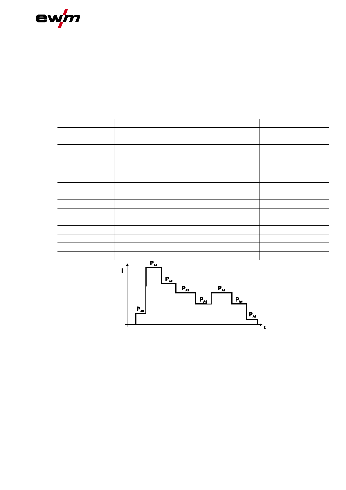
31.07.2014
Display
Meaning/explanation
Setting range
curr.prg.: X
Active main program A
0 to 15
P0 U2 :+0.0V
Arc length correction (offset Wire feed unit)
-9.9V to +9.9V
correction in program mode
wire feed unit)
P1 DV2 :+2.0m/m
Wire speed
0.1m/min. to 20.0m/min.
P1 U2 :+0.0V
Arc length correction
-9.9V to +9.9V
P1 DYN2: + 0
Dynamics/choke effect
-40% to +40%
P2 to P14
P2 to P14
P2 to P14
P15 DV2 :+2.0m/m
Wire speed
0.1m/min. to 20.0m/min.
P15 U2 :+0.0 V
Arc length correction
-9.9V to +9.9V
P15 DYN2: + 0
Dynamics/choke effect
-40% to +40%
5.16.11 MIG/MAG overview of parameters for M3.1x
Different welding tasks or positions on a workpiece demand various welding outputs (operating points) or
welding programs.
For each program, the
• Wire speed
• Correction of the arc length and the
• Dynamics / choke effect
can be set separately.
Up to 15 programs (P1 to P15) can be defined, and the user can switch between these programs during
the welding process.
Design and function
Definition of MIG/MAG welding tasks
P1 15 UK :+2.0V Limitation of the setting range for the voltage
P1 15 DK : 20% Restriction of the wire correction range
(for more details, see operating instructions for the
0.0V to +9.9V
0% to 30%
099-005366-EW501
Figure 5-27
63
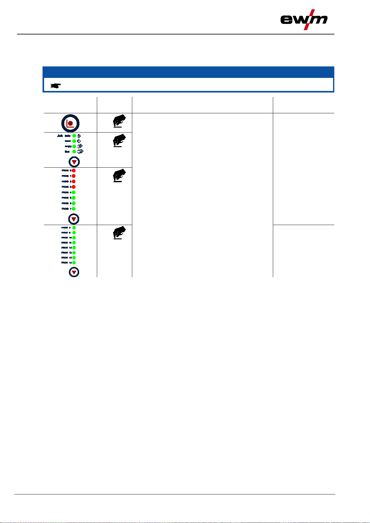
Design and function
"Special Mode" mode
31.07.2014
NOTE
Combination of buttons shown must be selected without pauses!
element
Select Special Mode
Program Steps
Special Mode
5.17 "Special Mode" mode
5.17.1 Selection
Operating
Action Result Display
1 x
1 x
2 x
1 x
64
099-005366-EW501

31.07.2014
NOTE
There is the option of switching the Hold fu n ction on and off for welding parameters.
Operating
element
Action
Result
Display
0= Hold function off
element
0= Relative wire feed speeds activated
element
Res. All 1
element
displayed
5.17.2 Switching the Hold function on and off
Design and function
"Special Mode" mode
Select the Hold function using the buttons
"Up" and "Down" (left)
Use the buttons "Up" and "Down" (right)
to switch the Hold function on or off.
1 = Hold function on
5.17.3 Wire feed speed switching (absolute / relative)
The following wire feed speeds are "relative programs" in the factory settings: DVStart (start program);
DV3 (reduced main program); DVEnd (end program). This means that they represent a percentage of the
wire feed speed DV2 (main program A) that has been set.
All wire feed speeds can also be specified as absolute values (independent of other values).
To do this, the absolute function (Abs-Fct = 1) must be configured as follows:
Operating
Action Result Display
Select function using the buttons "Up" und
"Down" (left)
Switch the function on and off using the "Up"
und "Down" (right) buttons
1= Absolute wire feed speeds ac tivate d
Hold-Fct 1
Hold-Fct 1
Hold-Fct 0
Abs-Fct 0
Abs-Fct 0
Abs-Fct 1
5.17.4 Resetting JOBs to status on delivery (Reset ALL)
Operating
Action Result Display
Select Res. All using the buttons "Up" and
"Down" (left).
5.17.5 Exiting "Special Mode" after making changes
Operating
Action Result Display
Saves the change No change
1 x
Exits Special Mode
1 x
Last selected
parameters are
099-005366-EW501
65
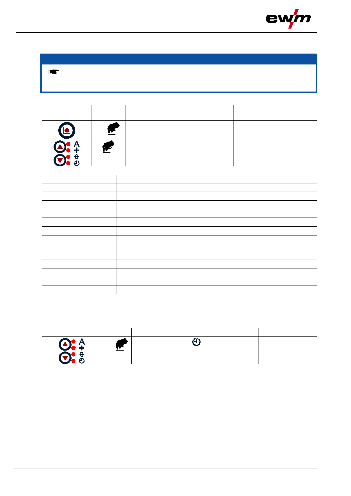
Design and function
"Job Info
" mode
31.07.2014
NOTE
relevant.
element
Select “JOB Info mode”
JOB Info
Parameter (display)
Explanation
Uist
Voltage
System
System status
JOB-Nr.
JOB number
akt. Prg.
Program number
Mode
Operating mode
Schweiss
Welding type
software)
Wire
Wire diameter
Material
Material type
Gas-Typ
Gas type
Verf.
Welding process
Operating element
Action
Result
Display
Operating time
5.18 "JOB Info" mode
Information on the current JOB is displayed in this mode.
• In JOBs 127 and 128 (TIG & MMA), it is not possible to select the mode as it would not be
Selection:
Operating
JOB Info parameter list:
Action Result Display
n x
Parameter selection See “JOB Info” parameter list
table
JOB-Typ Pre-defined or user-defined JOB
JOB-Text Text information relating to the JOB (can be edited using PC 300.Net
5.19 Operating time counter
The operating time is displayed in the format hhhh:mm:'h'. Four digits for the hours, two digits for the
minute, and a final 'h' symbol.
On the welding machine control
n x
The operating time is counted when current is flowing, and is written to non-volatile memory once per
minute.
Press until signal light comes on
display
66
099-005366-EW501

Design and function
31.07.2014
NOTE
The Job Manager can be used to load, copy or save JOBs.
The JOB is the welding task defined by the 4 main welding parameters; welding process,
material type, wire diameter and gas type.
One
Up to 15 operating points (P1 to P15) can be set in each program sequence.
The user has a total of 256 jobs available. 128 of these JOBs are pre
further 128 JOBs can be freely defined.
To ensure th
after at least 5 seconds have elapsed.
NOTE
It is normally possible to adjust all 256 JOBs individually. However, it is useful to assign
a separate JOB number to special welding tasks.
element
JOB has been copied
Copy to: xxx
Machine returns to Display mode
5.20 Organising welding task s (Mode "J OB Mana ge r")
Organising welding tasks (Mode "JOB Manager")
program sequence can be defined in each JOB.
at all the changes are active, the welding machine should be switched off
A distinction is made between two memory sectors:
• 128 factory-set, pre-programmed, fixed jobs (jobs 1 to 128).
Each welding task is assigned a JOB number (1 to 128).
• 128 freely definable JOBs (JOBs 129 to 256).
Each job can also be loaded directly (see chapter Loading an existing job).
5.20.1 Creating a new JOB in the memory or copying a JOB
Define the welding task which most closely matches the required application.
Copy the preset welding task (JOB 1-128) to the free memory sector (JOB 129-256):
Operating
Action Result Display
-programmed. A
Select JOB Manager mode JOB Manager
3 x
Select the JOB copy function using the buttons
x x
"Up" and "Down" (left)
Select the target JOB number (JOB 129-256)
x x
using the buttons "Up" and "Down" (right)
1 x
1 x
099-005366-EW501
Copy to: xxx
Copy to: xxx
67

Design and function
Organising welding tasks (Mode "JOB Manager")
31.07.2014
NOTE
JOB reference list (see Appendix).
Operating
element
Action
Result
Display
NOTE
If a pre-programmed JOB (JOB 1 to 128) has been changed accidentally, it can be reset
to the factory settings.
element
Select JOB Manager mode
JOB Manager
5.20.2 Loading an existing job
This function is used, for example, if the welding task (JOB) has been selected from the
3 x
Select JOB Manager mode JOB Manager
x x
"Up" and "Down" (left)
Select the JOB to be loaded using the buttons
Select JOB load function using the buttons
x x
"Up" and "Down" (right)
JOB has been loaded Load JOB: xxx
1 x
Machine returns to Display mode
3 x
5.20.3 Resetting an existing JOB to the factory setting (Reset JOB)
Operating
Action Result Display
3 x
Load JOB: xxx
Load JOB: xxx
x x
x x
1 x
1 x
Select the JOB reset function using the buttons
Res. JOB: xxx
"Up" and "Down" (left)
Select the JOB (JOB 1-128) to be reset to the
Res. JOB: xxx
factory settings using the buttons "Up" and
"Down" (right)
JOB has been reset Res. JOB: xxx
Machine returns to Display mode
68
099-005366-EW501

31.07.2014
Operating
element
Action
Result
Operating
element
Action
Result
Operating
element
Action
Result
Select parameter
5.21 Expert parameters
5.21.1 Selecting expert model parameters
1 x
1 x
1 x
Select expert model parameters
Design and function
Expert parameters
2 x
5.21.2 Selecting variables (5 model points)
1 x
Select model points 1 to 5
5.21.3 Setting parameters
Adjust parameter
099-005366-EW501
69

Maintenance, care and disposal
General
31.07.2014
DANGER
• Appoint only skilled persons for repair work (trained service personnel)!
Risk of injury from electric shock!
• Wait for 4 minutes until the capacitors have discharged!
6 Maintenance, care and disposal
Do not carry out any unauthorised repai rs o r modifications!
To avoid injury and equipment damage, the unit must only be repaired or modified by
specialist, skilled persons!
The warranty becomes null and void in the event of unauthorised interference.
Cleaning machines that are not disconnected from the mains can lead to serious
injuries!
• Disconnect the machine completely from the mains.
• Remove the mains plug!
6.1 General
When used in the specified environmental conditions and under normal operating conditions, this
machine is largely maintenance-free and requires a minimum of care.
There are some points, which should be observed, to guarantee fault-free operation of your welding
machine. Among these are regular cleaning and checking as described below, depending on the pollutio n
level of the environment and the length of time the unit is in use.
6.2 Maintenance work, intervals
6.2.1 Daily maintenance tasks
• Check that all connections and wearing parts are hand-tight and tighten if necessary.
• Check that all screw and plug connections and replaceable parts are secured correctly, tighten if
necessary.
• Remove any spatter.
• Clean the wire feed rollers on a regular basis (depending on the degree of soiling).
6.2.1.1 Visual inspection
• Check hose package and power connections for exterior damage and replace or have repaired by
specialist staff as necessary!
• Mains supply lead and its strain relief
• Gas tubes and their switching equipment (solenoid valve)
• Other, general condition
6.2.1.2 Functional test
• Check correct mounting of the wire spool.
• Welding current cables (check that they are fitted correctly and secured)
• Gas cylinder securing elements
• Operating, message, safety and adjustment devices (Functional test)
70
099-005366-EW501

Maintenance, care and disposal
31.07.2014
NOTE
procedures.
For further information, please see th e accompanying supplementary sheets "Machine
and Company Data, Maintenance and Testing, Warranty"!
6.2.2 Monthly maintenance tasks
6.2.2.1 Visual inspection
• Casing damage (front, rear and side walls)
• Wheels and their securing elements
• Transport elements (strap, lifting lugs, han dl e)
• Check coolant tubes and their connections for impurities
6.2.2.2 Functional test
• Selector switches, command devices, emergency stop devices, voltage reducing devices, message
and control lamps
• Check that the wire guide elements (inlet nipple, wire guide tube) are fitted securely.
6.2.3 Annual test (inspection and testing during opera tion)
The welding machine may only be teste d b y competent, capable personsl.
A capable person is one who, because of his tra ining, knowledge and experience, is
able to recognise the dangers that can o ccur while testing welding power sources as
well as possible subsequent damage and who is able to implement the required safety
Maintenance work
A periodic test according to IEC 60974-4 "Periodic inspection and test" has to be carried out. In addition
to the regulations on testing given here, the relevant local laws and regulations must also be observed.
6.3 Maintenance work
Repair and maintenance work may only be performed by qualified authorised personnel; otherwise the
right to claim under warranty is void. In all service matters, always consult the dealer who supplied the
machine. Return deliveries of defective equipment subject to warranty may only be made through your
dealer. When replacing parts, use only original spare parts. When ordering spare parts, please quote the
machine type, serial number and item number of the machine, as well as the type designation and item
number of the spare part.
099-005366-EW501
71

Maintenance, care and disposal
Disposing of equipment
31.07.2014
NOTE
• Observe the local regulations regarding disposal!
6.4 Disposing of equipment
Proper disposal!
The machine contains valuable raw materials, which should be recycled, and
electronic components, which must be disposed of.
• Do not dispose of in household waste!
6.4.1 Manufacturer's declaration to the end user
• According to European provisions (guideline 2002/96/EG of the European Parliament and the Council
of January, 27th 2003), used electric and electronic equipment may no longer be placed in unsorted
municipal waste. It must be collected separately. The symbol depicting a waste container on wheels
indicates that the equipment must be collected separately.
This machine is to be placed for disposal or recycling in the waste separation systems provided for this
purpose.
• According to German law (law governing the distribution, taking back and environmentally correct
disposal of electric and electronic equipment (ElektroG) from 16.03.2005), used machines are to be
placed in a collection system separate from unsorted municipal waste. The public waste management
utilities (communities) have created collection points at which used equipment from private households
can be disposed of free of charge.
• Information about giving back used equipment or about collections can be obtained from the
respective municipal administration office.
• EWM participates in an approved waste disposal and recycling system and is registered in the Used
Electrical Equipment Regist er (EAR) und er number WE EE DE 576 869 22.
• In addition to this, returns are also possible throughout Europe via EWM sales partners.
6.5 Meeting the requirements of RoHS
We, EWM AG Mündersbach, hereby confirm that all products supplied by us which are affected by the
RoHS Directive, meet the requirements of the RoHS (Directive 2002/95/EC).
72
099-005366-EW501

31.07.2014
NOTE
fundamental requirement for perfect operation!
Legend
Symbol
Description
Fault/Cause
Remedy
7 Rectifying faults
7.1 Checklist for rectify ing faults
The correct machine equipment for the material and process gas in use is a
Coolant error/no coolant flowing
Insufficient coolant flow
Check coolant level and refill if necessary
Air in the coolant circuit
"See 7.5 Vent coolant circuit chapter"
Functional errors
Machine control without displaying the signal lights after switching on
Phase failure > check mains connection (fuses)
No welding performance
Phase failure > check mains connection (fuses)
Various parameters cannot be set
Entry level is blocked, disable access lock "See 5.15 Protecting welding parameters from
unauthorised access chapter"
Connection problems
Make control lead connections and check that they are fitted correctly.
Insufficient coolant flow
Check coolant level and refill if necessary
Wire feed problems
Unsuitable or worn welding torch equipment
Adjust contact tip to wire diameter and -material and replace if necessary
Adjust wire guide to material in use, blow through and replace if neces sar y
Contact tip blocked
Clean, spray with anti-spatter spray and replace if necessary
Setting the spool brake (see "Setting the spool brake" chapter)
Check settings and correct if necessary
Setting pressure units (see "Inching wire electrodes" chapter )
Check settings and correct if necessary
Worn wire rolls
Check and replace if necessary
Wire feed motor without supply voltage (automatic cutout triggered by overloading)
Reset triggered fuse (rear of the power source) by pressing the key button
Kinked hose packages
Extend and lay out the torch hose package
Incompatible parameter settings
Check settings and correct if necessary
Arc between gas nozzle and workpiece (metal vapour on the gas nozzle)
Replace gas nozzle
Rectifying faults
Checklist for rectifying faults
099-005366-EW501
73

Rectifying faults
Checklist for rectifyi
31.07.2014
ng faults
Welding torch overheated
Insufficient coolant flow
Check coolant level and refill if necessary
Eliminate kinks in conduit system (hose packages)
Loose welding current connections
Tighten power connections on the torch and/or on the workpiece
Tighten contact tip correctly
Overload
Check and correct welding current setting
Use a more powerful welding torch
Unstable arc
Unsuitable or worn welding torch equipment
Adjust contact tip to wire diameter and -material and replace if necessary
Adjust wire guide to material in use, blow through and replace if neces sar y
Material inclusions in the tungsten electrode due to contact with filler material or workpiece
Regrind or replace the tungsten electrode
Incompatible parameter settings
Check settings and correct if necessary
Pore formation
Inadequate or missing gas shielding
Check shielding gas setting and replace shielding gas cylinder if necessary
Shield welding site with protective screens (draughts affect the welding result)
Use gas lens for aluminium applications and high-alloy steels
Unsuitable or worn welding torch equipment
Check size of gas nozzle and replace if necessary
Condensation (hydrogen) in the gas tube
Purge hose package with gas or replace
74
099-005366-EW501

31.07.2014
NOTE
The error code is signalled via the robot i n terface!
General system errors
1
The change of application signal of the power
source has not been updated.
Phoenix/alpha Q/Te
trix
Yes
4
Wire feed error
Phoenix/alpha Q/Te
trix
Yes
temperature error
trix
trix
power source
trix
power source
trix
power source
trix
trix
power source
11
Protective conductor error
Phoenix/alpha Q/Te
trix
No, switch off
power source
12
System quick stop
Phoenix/alpha Q/Te
Yes
trix
power source
7.2 Error messages
All products are subject to rigorous production checks and final checks. If, despite this, something fails to
work at any time, please check the product using the following flowchart. If none of the fault rectification
procedures described leads to the correct functioning of the product, please inform your authorised
dealer.
• If multiple errors occur, these are displayed in succession.
• Document machine errors and inform service staff as necessary.
Rectifying faults
Error messages
5 Inverter/inverter emergency stop circuit
6 Excess mains volt age Phoenix/alpha Q/Te
7 Insufficient mains voltage Phoenix/alpha Q/Te
8 Low water level Phoenix/alpha Q/Te
9 Gas error Phoenix/alpha Q/Te
10 Excess secondary circuit voltage Phoenix/alpha Q/Te
13 Internal error, please contact EWM Phoenix/alpha Q/Te
Phoenix/alpha Q/Te
No, automatic reset
No, switch off
No, switch off
No, switch off
Yes
No, switch off
trix
No, switch off
099-005366-EW501
75

Rectifying faults
Error messages
31.07.2014
Error
(value)
Meaning
Relevance
Error can be reset
49
Process ignition error
Phoenix/alpha Q/Te
trix
Yes
trix
trix
system or incorrect configuration
53
Switching to a non-ex iste nt doub le wir e feed er
the function to switch double wire feeders.
Phoenix/alpha Q
Yes
reduction device.
switched off)
trix
255
Unknown error
(1)
Phoenix/alpha Q/Te
trix
Yes
NOTE
The error numbers displayed on operatin g u n its are different from those transmitted via
the field bus.
An error has been assigned by the system which cannot be assigned. This situation can o ccur
with differences in the software versions between the power source and interface.
number
50 Arc break error Phoenix/alpha Q/Te
51 Emergency stop/excess temperature Phoenix/alpha Q/Te
52 Double wire feeder missing in the MIG/MAG
to system
Yes
No, automatic reset
Phoenix/alpha Q Yes
has been attempted in a system supporting
54 Reducing the open circuit voltage to the set
Phoenix/alpha Q No
values failed for power sources with voltage
99 No connection to power source (i.e. system
Phoenix/alpha Q/Te
No, automatic reset
(1)
76
099-005366-EW501

Panel)
31.07.2014
NOTE
A welding machine error is indicated by an error code being displayed (see table) on the
In the event of a machine error, the power uni t is shut down.
Category
a)
b)
c)
Error 1
- - x
Mains overvoltage
Check the mains voltages and compare with
(Un.Vol)
(Temp)
temperature
switch to "1")
Error 4
x x -
Low coolant level
Top off the coolant
current trigger on air cooling unit
Error 5
x - -
Wire feeder/speedometer
Check the wire feeder
M3.51 defective > inform Servic e
(gas)
with shielding gas monitoring)
(Se.Vol)
Error 8
- - x
Earth fault between welding
(Phoenix 330 only)
Separate the connection between the
Error 9
x - -
Fast cut-out
Rectify error on robot
RINT X12
RINT X12
Error 14
- x -
Wire feeder not detected.
Control cable not connected.
Check cable connection
Incorrect ID numbers
Check assignment of ID numbers (see the
(DV2?)
Control cable not connected.
(VRD)
reduction error)
7.3 Error messages (RC-Panel)
All products are subject to rigorous production checks and final checks. If, despite this, something fails to
work at any time, please check the product using the following flowchart. If none of the fault rectification
procedures described leads to the correct functioning of the product, please inform your authorised
dealer.
display on the machine control.
• If multiple errors occur, these are displayed in succession.
• Document machine errors and inform service staff as necessary.
Error
Possible cause Remedy
Rectifying faults
Error messages (RC-
(Ov.Vol)
Error 2
Error 3
(Water)
(Wi.Spe)
Error 6
Error 7
(no PE)
(fast stop)
Error 10
(no arc)
the connection voltages of the welding
- - x Mains undervoltage
x - - Welding machine excess
machine
Allow the machine to cool down (mains
Leak in the coolant circuit >
rectify the leak and top off the coolant
Coolant pump is not working > check excess
error
speedometer is not issuing a signal,
x - - Shielding gas error Check shielding gas supply (for machines
- - x Secondary excess voltage Inverter error > inform Service
wire and earth line
welding wire and casing or an earthed object
triggered by BUSINT X11 or
RINT X12
- x - Arc break
Check wire feeding
triggered by BUSINT X11 or
Error 11
(no ign)
- x - Ignition fault after 5 s
triggered by BUSINT X11 or
Check wire feeding
(no DV)
Error 15
Error 16
assigned during operati on
with multiple wire feeders.
- x - Wire feeder 2 not detected.
- - x VRD (open circuit voltage
"Changing ID number of wire feeder"
chapter)
Check cable connection
Inform Service
099-005366-EW501
77

Rectifying fa
ults
Error messages (RC
31.07.2014
Error
Category
Possible cause
Remedy
a)
b)
c)
M3.51 defective > inform Servic e
Welding machine control
Key button
CarExpert / Progress (M3.11)
Synergic S / Progress (M3.71) Picomig 305
WARNING
• Disconnect jumper 1 on PCB T320/1 (Tetrix / forceTig) or M320/1 (Phoenix / alpha Q)!
-Panel)
Error 18
(Wf.Sl.)
x - - Auxiliary drive/
speedometer error
Legend for categories (error reset)
a) The error message will disappear once the error has been rectified.
b) The error message can be reset by pressing a key button:
RC1 / RC2
Expert
alpha Q / Concept / Basic / Basic S / Synergic /
c) The error message can only be reset by switching the machine off and on again.
7.3.1 Interface for automated welding
No function of the external interr u p t equipment (emergency stop switch)!
If the emergency stop circuit has b een re alised using an external interrupt equip m ent
via the interface for automated weld ing, the machine must be configured for this setup.
If this is not observed, the power source will ignore the external interrupt equipment
and will not shut down!
Check auxiliary drive
tachogenerator not issuing signals.
not possible
78
099-005366-EW501

31.07.2014
NOTE
The query of the software versions onl y serves to inform the authorised service staff!
ENTER
+
A
l
0
l
0
Display
Setting/selection
List of the software
System bus ID/printed circuit board and version number are separated by a colon.
End of the list of software versions
NOTE
The printed circuit boards and software versions shown are displayed in an automated
process and vary according to the compone n ts that are connected and the versions.
Operating
element
Action
Result
Display
7.4 Display machine control s of t ware version
Rectifying faults
Display machine control software version
Figure 7-1
Start of the automated process
Software versions display
------- = System bus ID/printed circuit board
0.0.0.0.= Version number
List of the software
7.4.1 Resetting JOBs to status on delivery (Reset ALL)
Select Res. All using the buttons "Up" and
"Down" (left).
Res. All 1
099-005366-EW501
79

Rectifying faults
Vent coolant circuit
31.07.2014
NOTE
machines with water cooling.
To vent the cooling system always us e the b lue coolant connection, which is loca ted as
deep as possible inside the system (close to the coolant tank)!
7.5 Vent coolant circuit
Coolant tank and quick connect coupling of coolant supply and return are only fitted in
Figure 7-2
80
099-005366-EW501
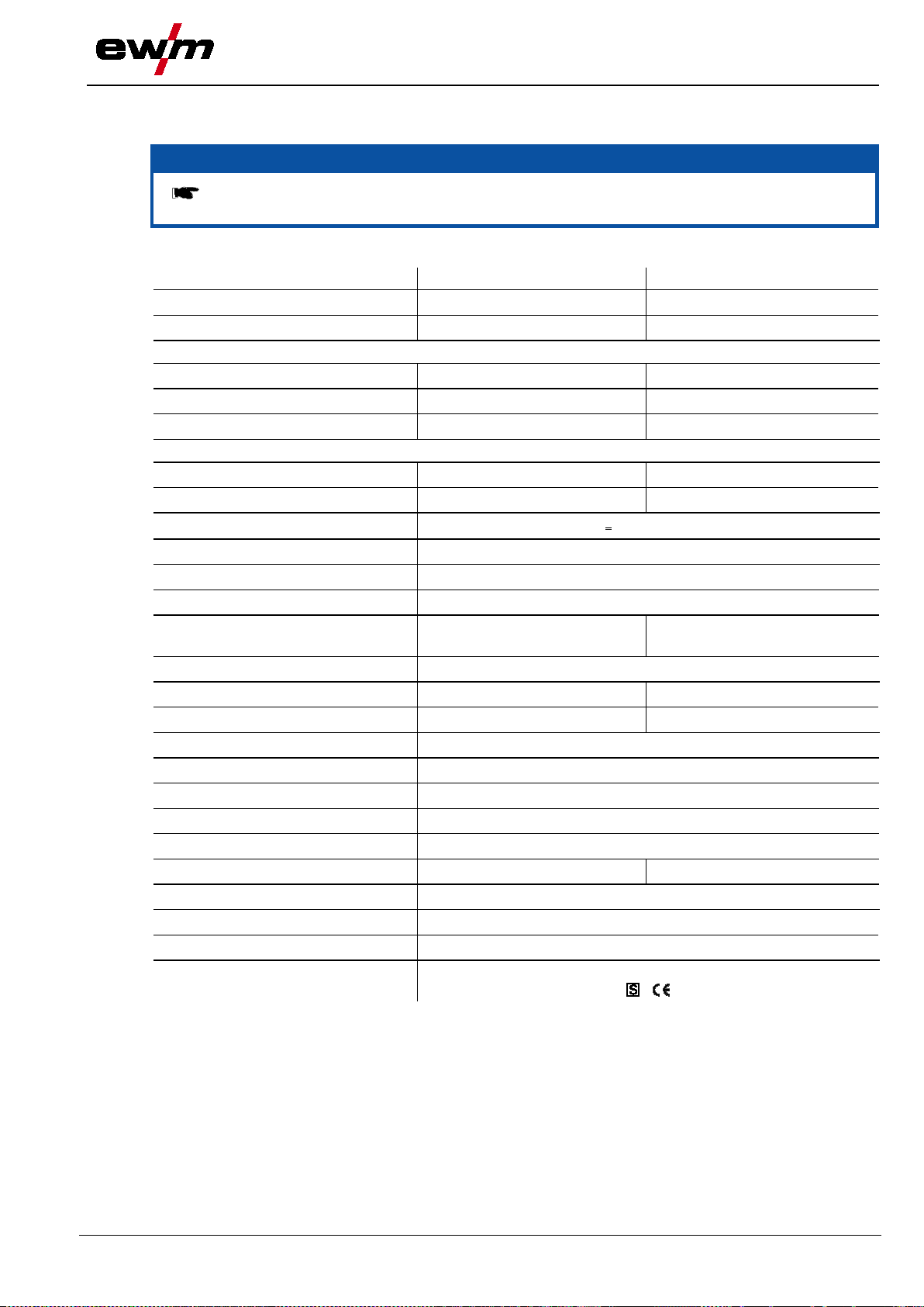
Technical data
31.07.2014
NOTE
Performance specifications and guarantee only in connection with original spare and
replacement parts!
352
552
Setting range for welding curr ent
Duty cycle at 40°C ambient temperature
100% DC
Duty cycle at 20°C ambient temperature
60% DC
Load cycle
Open circuit voltage
Mains voltage (tolerance)
(safety fuse, slow-blow)
Recommended generator rating
Protection classification
Workpiece cable
EMC class
Constructed to standard
/
alpha Q 352, 552 Puls
8 Technical data
8.1 alpha Q 352, 552 Puls
Setting range for welding voltage
60% DC
80% DC
100% DC
Frequency
Mains fuse
5 A to 350 A 5 A to 550 A
14.3 V to 31.5 V 14.3 V to 41.5 V
- 550 A
- 520 A
350 A 420 A
- 550 A
350 A 420 A
10 min (60% DC ∧ 6 min welding, 4 min pause)
93 V
3 x 400 V (-25 % to +20 %)
50/60 Hz
3 x 25 A 3 x 35 A
Mains connection cable
Max. connected load
cosϕ
Insulation class
Ambient temperature
Machine cooling
Dimensions L/W/H in mm
Weight
H07RN-F4G6
13.9 kVA 28.8 kVA
18.8 kVA 38.9 kVA
0.99
H
IP 23
-25°C to +40°C
Fan
70 mm2 95 mm2
780 x 375 x 625
85 kg
A
IEC 60974-1, -10
099-005366-EW501
81

Accessories
Connection cables, connection sockets
31.07.2014
NOTE
Performance-dependent accessories like torches, workpiece leads, electrode holders or
intermediate hose packages are available from your authorised dealer.
Type
Designation
Item no.
5POLE/CEE/32A/M
Machine plug
094-000207-00000
RA5 19POL 1x 5M
Connection cable, 19-pole, 5 m
092-001569-00005
RA10 19POL 1x 10M
Connection cable, 19-po le, 10 m
092-001569-00010
FRV 7POL 5 m
Extension/connecting cable
092-000201-00003
Type
Designation
Item no.
DMDIN TN 200B AR/MIX 35L
Manometer pressure regulator
094-000009-00000
Type
Designation
Item no.
BGA364X51X47
Panel for stacking machines
094-012294-00001
ON ZWIPA-CONNECTION
Retrofit option for third party INTPA strain relief
094-007890-00000
Type
Designation
Item no.
PALETTE ROB XX2
Transport pallet for use with robots
090-008275-00000
Type
Designation
Item no.
RINT X12 STANDARD
Robot interface
090-008291-00000
ATCASE
ON PLUG SET RINT X12
Optional EWM plug set, retrofit kit for RINT X12
092-001822-00000
Type
Designation
Item no.
PC300.NET software, cable and filter box
cable and SECINT X10 USB interface
QDOC9000 V2.0
Set consisting of interface, documentation software,
connection lead
090-008713-00000
ANALYSER
Software for control and status signal analysis
090-008778-00000
PQS-ARC
Quality assurance software
094-016609-00000
9 Accessories
9.1 Connection cables, connec t ion sockets
9.2 General accessories
9.3 Options
9.4 Transport systems
9.5 Interfaces
BUSINT X11 INTERBUS
Interbus industrial bus interface in casing 090-008225-00000
9.6 Computer communicati on
RC 300 DE Tablet PC with Microsoft Windows XP,
090-008238-00502
PC300.Net PC300.Net welding parameter software kit incl.
82
090-008777-00000
099-005366-EW501

31.07.2014
Type
Designation
Item no.
RK1
Reverse cooling unit
094-002283-00000
RK2
Reverse cooling unit
094-002284-00000
RK3
Reverse cooling unit
094-002285-00000
cool82 U45
Cooling module for robot welding machines
090-008280-00502
Type
Designation
Item no.
M drive 4 Rob 2 WE
MIG WF unit
090-004999-00502
M drive 4 Rob 2 WI
MIG WF unit
090-004999-00503
M drive 4 Rob 2 ZT
Robot intermediate drive
090-005137-00502
M drive 4 Rob 2 MF
MIG WF unit
090-005000-00502
M drive 4 Rob 3 RE
MIG WF unit
090-005110-00502
M drive 4 Rob 3 LI
MIG WF unit
090-005111-00502
9.7 Cooling units
cool82 U44 Cooling module for robot welding machines 090-008268-00502
9.8 Wire feed units
Accessories
Cooling units
099-005366-EW501
83

Circuit diagrams
alpha Q 352, 552 Puls
31.07.2014
NOTE
Original format circuit diagra ms are located inside the machine.
10 Circuit diagrams
10.1 alpha Q 352, 552 Puls
Figure 10-1
84
099-005366-EW501

Circuit diagrams
31.07.2014
alpha Q 352, 552 Puls
099-005366-EW501
Figure 10-2
85
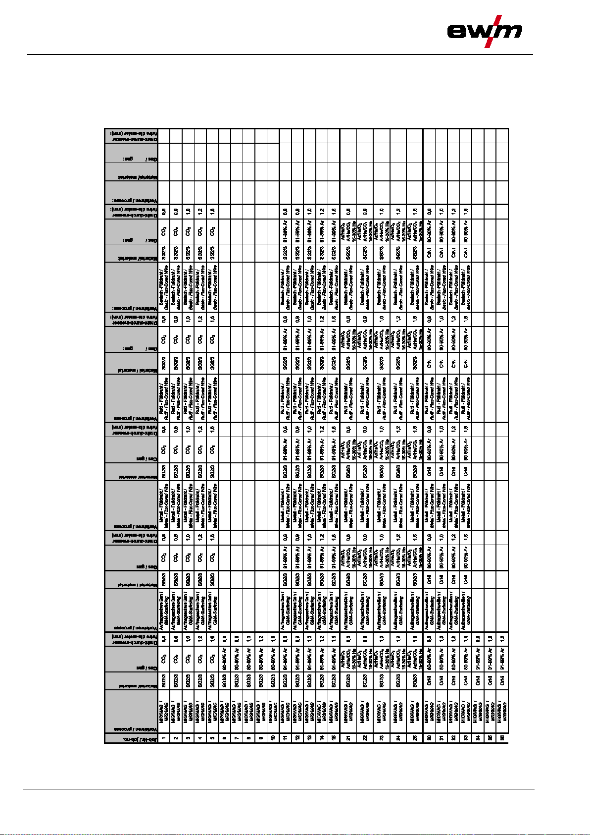
Appendix A
JOB
31.07.2014
-List
11 Appendix A
11.1 JOB-List
86
099-005366-EW501

Appendix A
31.07.2014
JOB-List
099-005366-EW501
87

Appen
dix A
JOB
31.07.2014
-List
88
099-005366-EW501

Appendix A
31.07.2014
JOB-List
099-005366-EW501
89
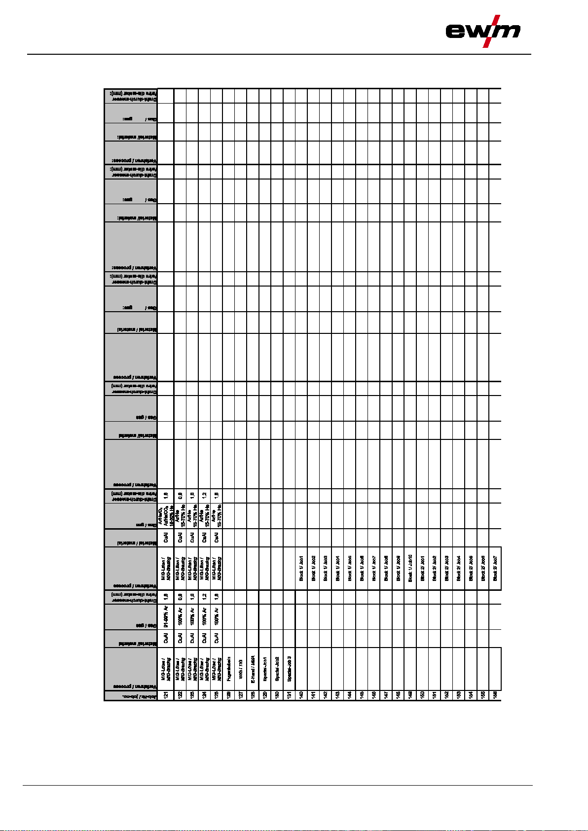
Appendix A
JOB
31.07.2014
-List
90
099-005366-EW501
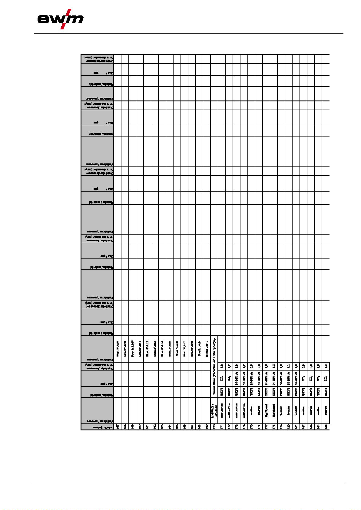
Appendix A
31.07.2014
JOB-List
099-005366-EW501
91

Appendix A
JOB
31.07.2014
-List
92
099-005366-EW501

Appendix A
31.07.2014
JOB-List
099-005366-EW501
93
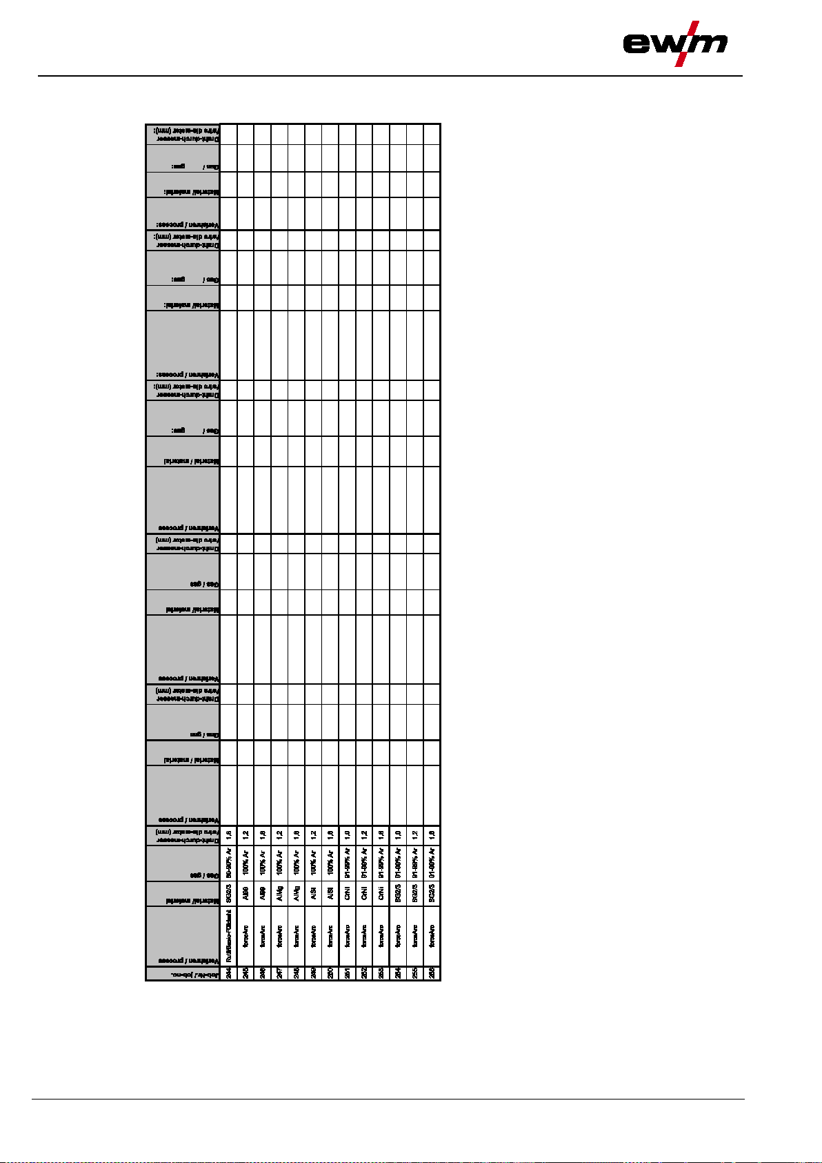
Appendix A
JOB
31.07.2014
-List
94
099-005366-EW501

31.07.2014
12 Appendix B
12.1 Overview of EWM branches
Appendix B
Overview of EWM branches
099-005366-EW501
95
 Loading...