

Smart Home User Instruction Manual
Open size: 490mm X 105mm
Fold size: 70mm X 105mm
490mm
105mm
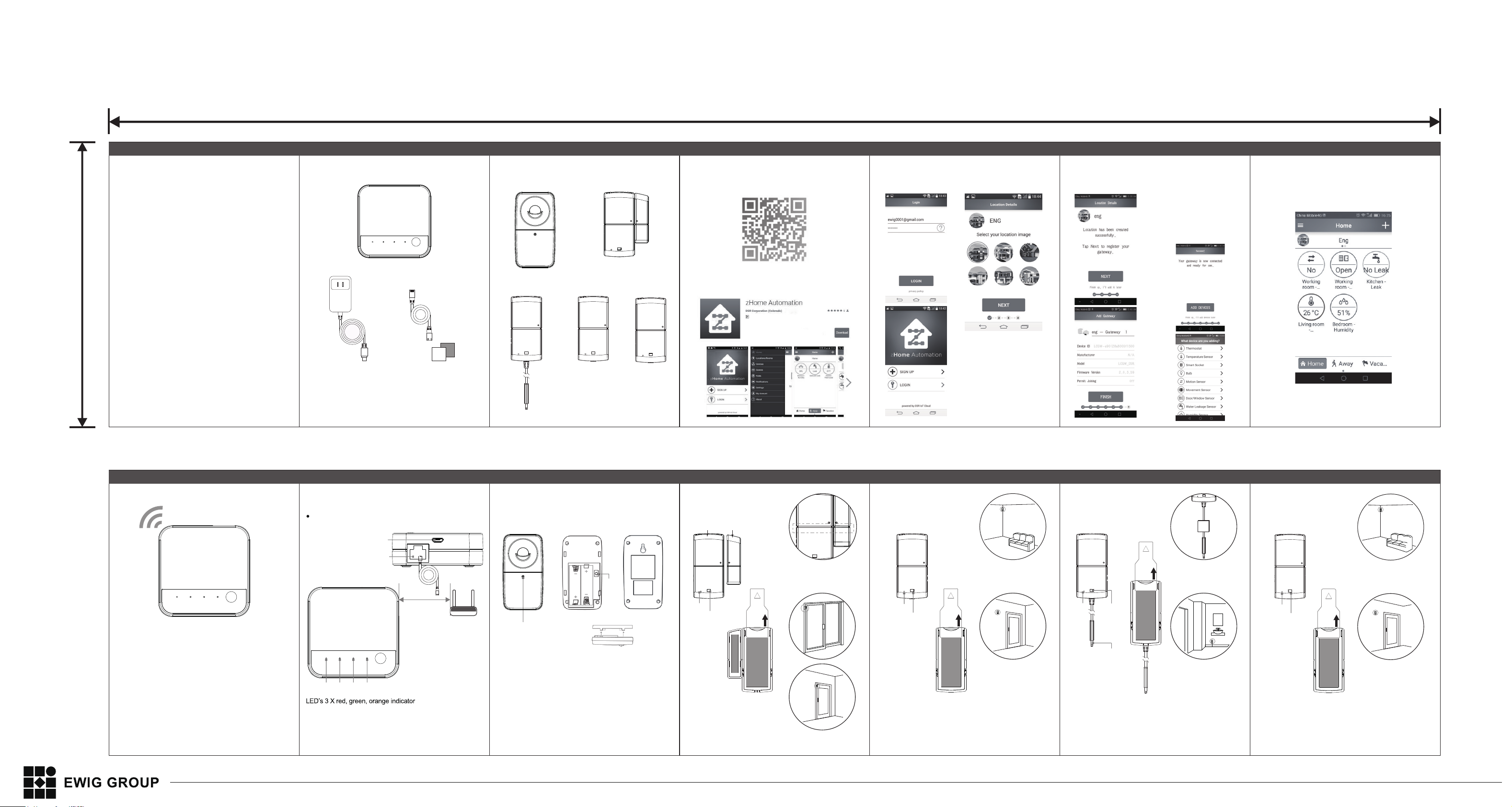
Smart Home System
User Instruction Manual
Smart Home system include following essentials:
Gateway
Ethernet Cable5V Adaptor
* This device design for indoor using,
no waterproof function;
GRP001
PIR sensor
GRP006
Water leakage sensor
GRP002
Door/window sensor
GRP007
Temperature sensor
GRP008
Indoor sensor
1st Step
APP download, install
https://play.google.com/store/apps/details?id=com.dsr.cloud.app
Scan QR code or type below link directly
Click the download to install APP automatically
Front side
2nd step:
sign up, login
3rd step:
Identify location
4th step:
Add gateway
5th step:
Add sensor
1.Press “add devices” to add sensor;
2.Select sensor type;
3.Pull out the insulation sheet ;
4.Select the install place for sensor;
5. Add others sensor as same step;
6th Step
User interface
Hardware Installation
RESET ERROR ZigBee POWER
This equipment has been tested and found to comply with the limits for a Class B
digital device, pursuant to Part 15 of the FCC Rules. These limits are designed to
provide reasonable protection against harmful interference in a residential installation.
This equipment generates, uses andcan radiate radio frequency energy and, if not
installed and used in accordance with the instructions, may cause harmful interference
to radio communications. However, there is no guarantee that interference will not
occur in a particular installation.
If this equipment does cause harmful interference to radio or television reception,
which can be determined by turning the equipment off and on, the user is encouraged
to try to correctthe interference by one or more of the following measures:
-- Reorient or relocate the receiving antenna.
-- Increase the separation between the equipment and receiver.
-- Connect the equipment into an outlet on a circuit different from that to which the
receiver is connected.
-- Consult the dealer or an experienced radio/TV technician for help.
Changes or Modifications not expressly approved by the party
responsible could void the user’s authority to operate this device.
This equipment complies with the FCC RF radiation exposure limits set forth for an
uncontrolled environment. This equipment should be installed and operated with a
minimum distance of 20 centimeters between the radiator and your body.
Gateway Installation
Connect the Gateway to internet via modem;
5V Adapter Connector
Ethernet cable connector
1m
Modem
a.Make sure 1m distance
between Gateway and
Modem to ensure RF
RESET ERROR ZigBee POWER
reset
3 2 1
1. Power LED - Green LED. It does show Ethernet activities;
2. Zigbee LED - Orange LED. It is used to provide information
on some special cases;
3. Error LED - Red LED. It is used to indicate error cases.
function;
b. When the gateway turn on,
the lights start to blink. When
the power light stays
continuously on,the gateway
is ready;
Sensor Installation
PIR sensor
reset
pairing indicator
Open the casing by detaching the back plate;
Place AA batteries into compartment;
Drill a hole in the wall at about 1.4 meters high,
use the provided wall plug to turn the screw in the wall;
Mount the sensor by sliding the hole in the top of back plate;
* Make sure the Lens is pointing upwards.
Back side
Door/Window sensor
Main body
reset
pairing indicator
Please pull out the insulation sheet
when the first time using.
Place the device on the position
want to install.
Clean the surface of the install position
Vice body
Make sure the dots on devices are
close to each other
remove
before
using
Temperature sensor
reset
pairing indicator
Please pull out the insulation sheet
when the first time using.
Place the device on the position
want to install.
Clean the surface of the install position
remove
before
using
Water Leakage sensor
remove
before
using
reset
pairing indicator
probe
Please pull out the insulation sheet
when the first time using.
Place the device on the position
want to install.
Clean the surface of the install position
EWIG COPYRIGHT © 2016 - ALL DISTRIBUTION UNDER NDA - NON-DISCLOSURE AGREEMENT.
Tie the cable by velcro,
ensure the probe can
touch to water
Indoor sensor
reset
pairing indicator
Please pull out the insulation sheet
when the first time using.
Place the device on the position
want to install.
Clean the surface of the install position
remove
before
using
PRELIMINARY DESIGN 20160519
 Loading...