

Page 1
®
TECHNICAL BULLETIN
Forced Air Zone Controls
Model UZC4 Zone Control
The UZC4 Zone Control System allows you to easily
upgrade an inefficient single zone HVAC system, into an
Automated, Multi-zone, Energy saving, Comfort producing,
Safety Minded, HVAC system. With Superior design, Intuitive
firmware, Building Code Compliant support, Simple setup
options, and Easy to understand wiring, the UZC4 Zoning
system is the Designer/Contractors dream. Combined with
Patented EWC motorized dampers and practically any Off-theshelf Conventional or Heat Pump style Thermostats,
EWC has set a New Industry Standard in Large
Residential and Commercial HVAC Air Zoning Systems.
Zone
Capacity
Compatible
HVAC
Systems
Compatible
Thermostats
Automatic
Heat/Cool
Changeover
Status LED
System LEDs
Damper LEDs
Operating
Power
TB-221
P/N 090375A0221 Revision I
Universal
FA
FA
24V
24V
RESET
MXR
MXC
M6
M4
M2
M1
M6
M4
M2
M1
M6
M4
M2
M1
M6
M4
M2
The main module controls four air zones
using 24 vac motorized air dampers and
may be expanded up to 20 zones, using
ZXM2 Expansion Modules. See page 23.
The UZC4 will Control 2, 3 & 4 stage
Conventional, GeoThermal or Dual Fuel
Heat pumps, without the need for dual
fuel kits. Also single or multi-stage Gas,
Oil, & Hydronic HVAC systems, with
single or two stage cooling and Constant
or Variable speed fan systems.
Compatible with most Off the shelf 1 or 2
stage Conventional Heat/Cool or Heat
M1
M6
M4
M2
M1
M6
M4
M2
M1
NC
NO
C
G
Y2
Y1
O
B
W1
W2
E
RC
RH
RC
LINK
W
E
Box Contents
Pump Therm ostats. All Mech anical,
Digital/Electronic, Dual Mode, and Internet
Compatible Thermostats that operate on
24vac. Battery powered or Power robbing
thermostats that draw less than 20 ma of
current are also compatible. Zone 1 will
accept One Zone Mode, Carbon Dioxide
Safety and Auxiliary/Dehumidify mode
inputs. See pages 9-11 & 14-17 for details.
The UZC4 Zo ne system features
auto m a t ic chan g e o ver from a n y
Manual
and
Automatic
Thermal
Circuit
Breakers
thermostat allowing for individual zone
comfort from the HVAC system.
The STATUS LED pulses as a steady
heart beat to indicate active Microprocessor status.
On board Multi-colored LED’s will
illuminate to indicate system status,
HVAC system mode, and active / inactive
zone identification. See page 22 for details.
Damper 1 thru Damper 20 green LEDs
Operating
Conditions
will indicate which zone dampers are
demanded to energize Open or Closed.
INPUT VOLTAGE: 19-30VAC 60 Hz
Transformer 40-100VA MAX. NEC Class
2.
CURRENT DRAW: Max 22VA @ 24VAC.
OVER-CURRENT PROTECTION: 4.0
amp or 100VA.
EWC Controls Inc. 385 Highway 33 Englishtown, NJ 07726 800-446-3110 FAX 732-446-5362 E-Mail- [email protected]
Copyright © 2004-2009 EWC Controls All Rights Reserved
Indoor Fan
Control
Leave this bulletin on the job site for future reference!
J1
HVAC ZONE
CONTROl SYSTEM
TB1
JMP1
R
D1
C
TB2
CB1
F1
K1
Z
O
4
N
E
K2
TB3
Z
O
3
N
E
K3 K4
TB4
Z
O
2
N
E
TB5
K5
Z
O
1
N
E
TB6
O
A
D
M
P
R
K7
TB7
E
B
K8
D
A
TB8
U
X
K9
R
L
Y
K10 K11
TB9
H
V
A
C
S
K12 K13
Y
S
T
E
M
JMP3
K14
RH
CONTROLS INC.
Englishtown, NJ
C
28
40
35
37
42
34
C54
R20
R19
HP
SYSTEM
>
HP
DF
< >
OFF
FAN PRG
<
PURGE
90
s
<
STAGES
OAS
<
OFF
50
<
OFF
SAS
<
FAN
GAS
<
TSTAT
HC
>
1
CS#
<
RV
O
<
OFF
<
RA
AUX RLY
<
RAS
OFF
<
0
RA LMT
<
FAN CTRL
ANY
<
STATUS
OAS
SAS
RAS
ZONE
ZONE
ZONE
ZONE
DMPR
BYPASS
AUX RELAY
FAN
COMPRESSOR2
COMPRESSOR1
REV
EMERGENCY
C53
CONV
%
>
>
ZDL
R48
C17
Y1
R50
SW1
LIMIT
LIMIT
LIMIT
4
3
2
1
VALVE
COOLING
LIMIT
R2
>
>
R
>
>
>
>
2
B
>
>
>
TIMER
RESET
OPEN
OPEN
OPEN
OPEN
43
GAS
>
180
TMR
>
ON
ON
HYDRO
HP
ON
>
ON
+10
U14
U19
OPENOA
DMPR
R52
R53
R54
R55
R63
21
14
7
OFF
STAGING
OAS
TIMER
R1
C1
C2
D2
LED19
GROUND FAULT
JMP2
D3
R5
D4
R6
D5
R7
D6
R8
D7
R9
D8
R10
D9
R11
D10
R12
D11
R13
D12
R14
D13
R15
D14
W1 HEAT
W2 HEAT
R16
D15
R17
D16
R18
140
130
46
120
49
110
52
1ST
STAGE
HEATING
LIMIT
R3
R21
R22
BANK1
R29
R30
ON
s
DA
Z
1
>
U1
R31
R32
R33
R34
R35
R36
BANK2
R37
R38
R39
R40
R41
R42
R43
R44
C8
C7
U15
R47
C10C9C11
C12
C13
C14
C15
C18
R49
C19
C22
R58
C21
R51
CPU
RESET
U17
U18
LED1
LED2
LED3
LED4
LED5
LED6
LED7
LED8
LED9
LED10
LED11
LED12
LED13
LED14
LED15
LED16
LED17
LED18
Z1
R56
R57
R60
R61
26
150
19
160
12
170
5
STAGE
MULTI
DIFFERENTIAL
R4
R23
D17
R24
D18
R25
D19
D20
R26
D21
R27
R28
D22
R50
R45
C3
R46
D23
U2
C4
U3
C5
U4
C6
U5
C16
J2
U6
C20
U7
SW2
C23
U8
C24
U9
C52
R135
R134
UZC4
33
40
47
R64
HEAT
R65
S
R66
E
C25
R67
R69
R71
R75
R77
R79
R83
R85
R87
R91
R93
R95
R99
R101
R103
R107
R109
R111
R112
R115
R117
R119
R120
R123
R125
R126
R127
R128
R129
R130
R133
SW3
R68
R70
R72
R73
R74
R76
R78
R80
R81
R82
R84
R86
R88
R89
R90
R92
R94
R96
R97
R98
R100
R102
R104
R105
R106
R108
R110
R113
R114
R116
R118
R121
R122
R124
R130
R132
N
C26
S
O
C27
R
S
TB11
C28
T
C29
S
T
C30
A
T
4
C31
C32
TB12
C33
T
S
C34
T
A
C35
T
C36
3
C37
TB13
C38
T
C39
S
T
A
T
C40
2
C41
C42
TB14
C43
T
S
C44
T
C45
A
T
1
C46
C47
C48
C49
C50
C51
EMERGENCY
NORMAL
* UZC4 Zone Control Panel
* Supply Air Sensor
* Technical Bulletin TB219
* Mounting Hardware
The main UZC4 module has a Manual
Reset circuit breaker with a Ground
Fa ult In dica tor t hat p rote cts al l
connected modules and thermostat
circuitry. All modules have separate
damper motor Thermal Breakers too.
They protect the damper motor circuitry
from shorts in the field wiring. The
breakers will not protect against shorts
in the HVAC system wiring.
CAUTION: When the thermal
breaker is tripped it will get quite
hot. To reset the breaker: Shut off
power to the panel. Find and repair
the short. Restore the 24VAC power.
TEMPERATURE: -20° to 160°F (-29° to 71°C)
HUMIDITY: 0% - 95% RH Non-Condensing.
The UZC4 allows constant operation of
the Indoor Fan by Thermostat #1 only, or
by each individual thermostat. When
controlled by thermostat #1, All Zone
dampers will respond. When controlled
individually, Zones not calling for
continuous fan will close.
TB10
TB15
Figure 1.
SAS
SAS
OAS
OAS
RAS
RAS
C
W1
W2
O
Y1
Y2
R
G
C
W1
W2
O
Y1
Y2
R
G
C
W1
W2
O
Y1
Y2
R
G
C
W1
W2
O
Y1
Y2
R
G
ONE
ZONE
AUX R
CO
CO
1
E
B
E
B
E
B
E
B
2
2
Page 2
UZC4 STANDARD FIRMWARE AND HARDWARE FEATURES
Indoor Fan
Control
During
Heating
Built-In
Timer
Settings
Definitions
are explained
below
*Short Cycle
Timer
*Changeover
Timer
*Inter-stage
Timer
*Opposite
Mode
Delay Timer
*Staging
Timer / OAS
21
14
7
OFF
MULTISTAGE
Timer / OAS
28
35
42
OFF or
7 to 42
minutes or
7 to 42
degrees F.
Use when Timer
or Outside Air
Changeover is
required.
See Page 7
*Supply/Return
Air Limit
Delay Timer
2
EWC Controls Inc. 385 Highway 33 Englishtown, NJ 07726 800-446-3110 FAX 732-446-5362 E-Mail- [email protected]
A dip switch is provided to enable automatic fan
operation in heat mode. Useful for straight
electric heat or hydronic heat applications.
NOTE: Fan mode is automatically set when
Heat Pump is selected.
The panel has built-in delay timers that
insure safe & reliable operation.
*Short Cycle Timer
*Changeover Timer
*Inter-stage Timer
*Opposite Mode
3 minutes - Fixed.
4 minutes - Fixed.
2 minutes - Fixed.
20 minutes - Fixed.
Delay Timer
*Staging Timer
OAS Setting
*Supply / Return
7 to 42 minutes
or 7 to 42 ° F
3 minutes - Fixed.
Air Limit Delay Timer
When all zone demands are satisfied, the
panel will not resume the same mode
operation for a minimum of 3 minutes.
When a demand to Change Over has
been honored. A 4 minute delay timer
prevents the system from rapidly
changing between Heat to Cool, or Cool
to Heat mode.
2 minute time delay that occurs between
thermostatic demands to stage up or down.
A 20 minute delay must expire, or all
act i ve zone( s) m ust sat i sf y, bef or e
t h e U ZC 4 w i ll h o n o r a t h e r m o s t a t
d e m a n d t o c h a n g e o v e r t o t h e
opposite mode of system operation. The
delay is fixed & cannot be changed or defeated.
The STAGING TIMER sets the
amount of continuous & cumulative
call time in 1st stage, before second
stage heat or cool is energized. Also
applies to 3rd & 4th stage heat.
NOTE: The potentiometer also
serves as the 2nd or 3rd stage Heat,
Outside Air Changeover Setting.
The UZC4 can inhibit 2nd or 3rd stage
heat based on Time or Outside Air
Temperature. All staging scenarios
depend upon the type of thermostat
used. See page 5 & 7 for details.
NOTE: An Optional OAS Sensor is required to
use the OAS feature. NOTE: Y2 Output
defaults to 30 minutes, if OAS is chosen and
single stage thermostats are used.
The time delay of 3 minutes must
expire before the UZC4 will reenergize heat or cool mode. This
occurs when the processor detects
the supply or return air temperature is
higher or lower than the Heat/Cool
limit settings.
Cooling and Heating Limit Controls
The operational sequence of the limit controls depends upon the
dip switch settings chosen on the UZC4 main module. Multistage
Heat Pump sequence will differ from Conventional Gas/Electric.
43
40
37
34
COOLING LIMIT
130
120
110
1st STAGE
HEAT LIMIT
19
12
5
MULTI STAGE HEAT
DIFFERENTIAL
Example:
Hi Temp. limit=130
Plus M. stg T= 40
New limit F = 170°
Timer Reset
BUTTON
CPU Reset
BUTTON
Emergency
Heat
Switch
140
26
TIMER
RESET
SYSTEM
RESET
NORM
46
52
150
170
33
40
47
EM
49
160
Press & Hold the SYSTEM RESET
button for 5 seconds. That will reset
the Main & Expansion modules on a
UZC4 Zoning System.
NOTE: A three minute startup delay
occurs whenever the CPU Reset button
is pushed, upon any initial power up, or
when a power failure has occurred.
An On-Board Switch is provided that
allows the user to set the system to the
Emergency heat mode. This switch is
shown in the NORMAL position.
NOTE: An Emergency terminal is also
provided at every Thermostat terminal
b l o c k , a l l o w i n g H e a t P um p
Thermostats to be connected to every
zone.
Th e Ad j ust a ble C ool i ng L i mi t
potentiometer sets the supply air
temperature at which the 1st & 2nd
stage cooling is cycled off and the fan
continues to run, allowing the coil to
warm up.
Th e Adj u sta b le H e a ti n g L imi t
potentiometer sets the 1st or 2nd stage
heat supply air temperature, at which
the heating is cycled off and the fan
continues to run, allowing the heat
exchanger or coil to cool down.
The Adjustable Mul tistage H eat
differential potentiometer sets the 2nd
and/or, 3rd, & 4th stage heat supply air
temperature, at which the heating is
cycled off and the fan continues to run,
allowing the heat exchanger or coil to
cool down.
NOTE: Allows the supply air sensor to
be installed in the supply air plenum,
regardless of the coil/heat exchanger
configuration. Allows the installer to
fine tune virtually any multistage
heating system!
Momentarily pressing the TIMER
RESET button will clear any Active
Time Delay. This enables you to test
and certify the installation faster.
NOTE: Do not use sharp objects to
press the button. Use your finger tip or
the eraser head of a pencil.
Page 3
UZC4 ADVANCED FIRMWARE AND HARDWARE FEATURES CONTINUED
*FIRE ALARM
INTERLOCK
FEATURE
Building
Code
Compliant
Support
Fire Alarm
Activation
Over-rides
ALL functions
and features
All Connected
Dampers will
close and the
HVAC system
will shut down
*Demand
Based
Ventilation
CO2 MONITOR
FRESH AIR
INTERFACE
FEATURE
Building
Code
Compliant
Support
This feature is
not affected by
Heat/Cool
Operations
Fire Alarm
Activation
Over-rides
this feature
EWC Controls Inc. 385 Highway 33 Englishtown, NJ 07726 800-446-3110 FAX 732-446-5362 E-Mail- [email protected]
The UZC4 includes a Fire Alarm
system interlock feature.
Wire the UZC4 into your building
Fire Alarm system, and achieve full
HVAC system shutdown, and
Closure of all Duct dampers, in the
event of Fire Mode Activation.
The circuit is normally closed and
must open to activate this mode. A
Fail Safe dry contact is required on
the Fire Alarm System.
When the Fire alarm system resets
to normal, the UZC4 will also
resume normal operation. Clip the
on-board jumper and wire as shown
on page 17.
The UZC4 includes a Carbon
Dioxide and Fresh Air interface
feature.
Wire the UZC4 up to a separate
&
CO2 Monitor with auxilary dry
contacts. When the CO2 Monitor
activates, the UZC4 will open a
fresh air damper connected to it’s
OA damper terminal block, and
start the HVAC system fan.
The circuit is normally open and
must close to activate this mode. A
normally open dry contact is
required on the C02 Monitor or
Fresh air Timer or Other Device.
When the CO2 monitor resets to a
normal CO2 level, the UZC4 will
close the fresh air /auxilary damper.
Other external dry contact devices
can be connected to the CO2
terminals such as a Manual Switch,
Enthalpy Control, or ClockTimer.
See page 16.
NO T E: Co o li ng & He at i ng
operations are not affected by
activation of this feature.
NOTE: Activation of the Fire Alarm
Interlock feature will over-ride the
CO2 Monitor feature.
AUXILARY or
DeHUMIDIFY
INTERFACE
RELAY
Enhanced
Comfort
Solution
Auxiliary “dry”
SPDT output
This feature is
affected by
Heat/Cool
Operations
Fire Alarm
Activation
Over-rides
this feature
ELECTRONIC
BYPASS
DAMPER
SUPPORT
FEATURE
Enhanced
Airflow
Solution
Fire Alarm
Activation
Over-rides
this feature
The UZC4 includes an Auxiliary
Interface Input and SPDT action
Dry Contact Output. This allows
the Installer to connect various
Aux i lia r y co n trol s suc h as
Humidify or DeHumidify controls.
Simply connect the Controlled
Device or Circuit to the “Output”
dr y c on ta ct s a nd ac hi ev e
integrated control without 3rd
party isolating relays.
See Page 14 and 15 for example
control and wiring solutions.
The Auxiliary input logic can be
field selected as (DA) Direct Acting
to humidify or (RA) Reverse Acting
to Dehumidify.
The UZC4 activates a unique algorithm to
rapidly de-humidify the home without
over-cooling it. See page 14.
The UZC4 includes support for
an Electronic Bypass Damper.
Wire up a EWC Model “EBD”
Bypass Damper to ach ieve
precise control of the HVAC
system static pressure and
bypass damper operations.
Wire up the Model “EBD” damper
as shown on page 17.
The UZC4 defaults the Bypass
Damper to the “Open” position
during “IDLE” periods. It will also
maintain that position for 45
seconds; at the start of any
thermostat demand for Heating,
Cooling, or Fan only Operation.
The 45 second time delay
allows a constant or variable
speed fan to start in a “Quiet
Mode” and does away with
noisy air duct velocities upon
system startup.
A Latent cooling effect is also
achieved by using this feature.
After 45 seconds the UZC4 will
release control of the system static
pressure to the EBD diaphragm
control and a gradual increase in
sy st em st at ic pr es su re i s
achieved. NOTE: The UZC4 will not
resume control of the “EBD”, until the
next “IDLE” period begins.
3
Page 4
UZC4 ADVANCED FIRMWARE AND HARDWARE FEATURES CONTINUED
RETURN AIR
MONITORING
FEATURE
Enhanced
HVAC System
Safety and
Energy
Savings
Solution
Note: If this
feature is
“Enabled”
but the “RAS” is
not connected or
is not detected;
The “RAS” LED
will blink rapidly
as a warning and
The UZC4 will
not allow RAS
operations to
occur.
Note: When the
Return Air sensor
detects a return
air temperature
between the
Stage Up Value
and
the Stage Down
Value, the “RAS”
LED will blink
slowly as a
warning. The UZC4
will also hold at the
current staging
until the system
status changes
sufficiently to
allow a stage up
or down.
The UZC4 includes a RETURN AIR TEMPERATURE SENSING feature.
Connect an OPTIONAL Return Air Sensor (#RAS) to the UZC4 and achieve the ability to
STAGE DOWN the HVAC system if the return air temperature exceeds the return air
temperature limit set points. Set the “RAS” Dipswitch #6 to the “ON” position, and
choose either (0) or (+10) at the “RA LIMIT” Dipswitch # 7. Both switches are located
on the Dipswitch Bank#2.
The UZC4 will now monitor the return air temperature and allow Stage up, or if necessary
Stage Down the cooling or heating operation to maintain a return air temperature within
the following values. As stated above, choose either (0) to accept the default return air
limit values for your particular HVAC system or choose (+10) to offset the default values
10 degrees higher. Note: The (+10) offset applies to heating operations only. The default
return air temperature limit set points for cooling operations cannot be offset.
RETURN AIR LIMITS DURING HEATING CYCLE FOR HEAT PUMPS ONLY:
Default (0) set points:
If the Return Air temperature is:
80 degree F. or below, Stage Up is allowed.
105 degree F. or above, Stage Down is forced.
Default (+10) set points:
If the Return Air temperature is:
90 degree F. or below, Stage Up is allowed.
115 degree F. or above, Stage Down is forced.
RETURN AIR LIMITS DURING HEATING CYCLES FOR GAS, OIL, STRAIGHT ELECTRIC:
Default (0) set points:
If the Return Air temperature is:
80 degree F. or below, Stage Up is allowed.
115 degree F. or above, Stage Down is forced.
Default (+10) set points:
If the Return Air temperature is:
90 degree F. or below, Stage Up is allowed.
125 degree F. or above, Stage Down is forced.
RETURN AIR LIMITS DURING COOLING CYCLES FOR ALL HVAC SYSTEM TYPES:
Default (0) set points:
If the Return Air temperature is:
65 degree F. or above, Stage Up is allowed.
55 degree F. or below, Stage Down is forced.
Default +10 applies to heating operations only.
The Return Air Sensing Feature cannot cycle the 1st stage equipment off-line. It can only force a
4
EWC Controls Inc. 385 Highway 33 Englishtown, NJ 07726 800-446-3110 FAX 732-446-5362 E-Mail- [email protected]
Stage Down when the equipment is in 2nd stage cool or 2nd, 3rd, or 4th stage heat, and the selected
return air set points above have been exceeded. The Supply Air Sensing feature is the only monitor
that can cycle the 1st stage equipment off-line.
A three minute delay will occur after a forced stage down. If a stage up demand is present, the UZC4
will allow the stage up to re-occur when the three minute delay has expired and the return air
temperature is back to normal.
The UZC4 will automatically adapt to the “GAS,OIL,ELECTRIC” set points when a Heat Pump
system stages up to Fuel or Auxiliary mode.
This powerful feature will enhance the efficiency of your Zoned HVAC system and protect the
equipment from excessive bypass temperatures during low load conditions.
Page 5
UZC4 ADVANCED FIRMWARE AND HARDWARE FEATURES CONTINUED
MODULE TO MODULE FACTORY POWER WIRING
The UZC4 includes Factory Power Wiring on
all expanded systems. The 24 vac power to the
expansion modules is fed through the bus
cable. The bus cable feeds power to all module
processors & thermostats. Damper Motor
terminal blocks are isolated and powered
separately. This simplifies your wiring,
reduces the chances of polarity reversal and
allows more connected dampers per zone.
DIRECT DUAL FUEL COMPATIBLE FIRMWARE
The UZC4 is fully compatible with Dual Fuel
Heat Pumps, and other Hybrid HVAC systems.
Dual Fuel kits are not required. Select staging
based on Adjustable Time Delay, an Optional
Outside Air temperature Sensor, or allow the
thermostats to control staging. The intelligent
firmware does the rest.
* 7 TO 42 MINUTE STAGE UP TIME DELAY SETTINGS
RAPID DE-HUMIDIFY FIRMWARE
The UZC4 will perform a unique de-humidify
function when a demand to de-humidify is
detected at the Auxilary Input terminal. The
UZC4 will energize the Emergency heat relay to
activate one electric strip bank at the same
time the Y1 cool is active, so long as the
demand to de-humidify is detected. This
powerful feature will rapidly de-humidify your
home, and tempers (reheats) the supply air to
prevent over-cooling. See Page 14 for details.
CO2 DEMAND BASED VENTILATION SUPPORT
The UZC4 includes support for Demand Based
Ventilation Control scenarios. Designed to
help meet or exceed local building codes and
ASHRAE ventilation standards. Simply
connect your CO2 Monitor and a Fresh Air
damper to the UZC4.
*ZONE DEMAND LIMITING FEATURE
* 7 TO 42 DEGREE F. OUTSIDE AIR CHANGEOVER
* MULTI- STAGE HEAT ADJUSTABLE LIMIT CONTROL
* ELECTRONIC BYPASS DAMPER SUPPORT
* AUXILARY MULTI-FUNCTION SUPPORT RELAY
THERMOSTATIC DEMAND STAGE UP ON ALL ZONES
The UZC4 is the first Zone Control System to allow 4 stage thermostats to be connected to all zones
* STATUS LED’s ARE INCLUDED ON ALL MODULES
*ONE ZONE MODE SETBACK CAPABILITY
* SIMPLIFIED WIRING AND SYSTEM SETUP
* FIRE ALARM INTERFACE
The UZC4 is capable of numerous staging sequences depending on the type of HVAC system being
controlled, the type of thermostats connected, and the programmed staging sequence you desire.
As always you can still control a multi-stage HVAC system using inexpensive single stage thermostats
and sequence the staging by on-board adjustable time delay, or by using an optional outdoor air sensor
(OAS) and sequence the staging via an outdoor air set point.
You can still control a state of the art multi-stage Heat Pump using single or two stage conventional
thermostats and sequence the staging by time delay or outside air set point.
You can choose to control most any multi-stage Heat Pump or Conventional HVAC system with OEM
multi-stage thermostats on all zones. The UZC4 can be programmed to stage up or down based on the
thermostat inputs from each zone. The UZC4 allows a level of versatility that has never before been
offered by any zoning company. You can choose to install 3 or 4 stage thermostats on the largest zones, 2
stage thermostats on medium sized zones and single stage thermostats on the small zones.
To achieve staging via thermostatic demand only; Choose (TMR) Timer setting on Dipswitch #5 Bank 1
And then set the Multi-Stage Timer setting to (0) Zero. Setting the Timer to zero disables Timed Staging
and the UZC4 will stage up or down only when the thermostat(s) demand it.
EWC Controls Inc. 385 Highway 33 Englishtown, NJ 07726 800-446-3110 FAX 732-446-5362 E-Mail- [email protected]
5
Page 6
Selecting the Options Using the DIP Switches
***FS = Factory Settings
RECORD YOUR DIP SWITCH
SETTINGS HERE
Programming and setting up the
UZC4 is very easy! Check the
Switch Legend and refer to the
following pages for an explanation of
each dip switch function and choose
your settings. Some functions may
not apply to your application. Use a
pencil to fill in the square & record
your settings. If the settings get
changed later on, you will have a
record of the original settings.
NOTE: When you choose “HP” at
switch #1, Bank 1, the fan mode is
automatically set for you. There is no
need to move switch #8, Bank1.
Leave it in the “GAS” factory setting.
RECORD YOUR DIP SWITCH
SETTINGS HERE
Bank1
Bank2
SWITCH LEGEND
HP < SYSTEM > GAS
1
1
2
2
3
3
4
4
5
5
6
6
7
7
8
8
1
1
2
2
3
3
4
4
5
5
FS
DF < HP > CONV FS
FS OFF < FAN PRG > ON
90s < PURGE > 180s FS
OAS < STAGES > TMR FS
FS OFF < 50% R > ON
FS OFF < SAS > ON
FS GAS < FAN > HYDRO
HC < TSTATS > HP
FS
FS1 < CS# > 2
FS O < RV > B
FS OFF < ZDL > ON
RA < AUX RLY > DA FS
6
6
7
7
8
8
FS OFF < RAS > ON
FS 0 < RA LIMIT > +10
ANY < FAN CTRL > Z1 FS
Detailed explanations of each Dip Switch Function are included on the following
pages. Please study and familiarize yourself with all of the functions and features, prior
to activating the Zoned HVAC system. Not all features will apply to your application.
The UZC4 comes from the factory pre-set to operate a 2 stage Heat Pump using
heat pump thermostats to control the staging.
Failure to properly set all dip switches to the correct and/or desired positions will result
in improper operation of the controlled HVAC System.
Please read and study the entire Technical Bulletin and if necessary, Call the EWC
Technical Support Hotline when assistance is required.
Leave this Technical Bulletin with the Home or Building Owner for future reference.
CONTINUED ON NEXT PAGE...
6
EWC Controls Inc. 385 Highway 33 Englishtown, NJ 07726 800-446-3110 FAX 732-446-5362 E-Mail- [email protected]
Page 7
Selecting the Options Using the DIP Switches - BANK1
HP < SYSTEM > GAS
1
Choose the type of HVAC system you want to control. Select HP, if your system is any type of heat pump. Select GAS,
if your system is a any type of Gas / Oil furnace, or any straight Electric furnace or Hydronic (hot water / steam)
heating system.
DF < HP > CONV
2
If you chose “HP” at switch #1, then choose the type of Heat Pump you want to control. Select DF, if your system is a Dual Fuel
heat pump with Gas or Oil furnace backup heat. Select CONV, if your system is a Conventional heat pump with Electric resistance
backup / supplemental heat. Also applies to Ground source / Geothermal heat pumps with Electric backup heat.
OFF < FAN PRG > ON
3
Select ON, if you want the UZC4 to force the indoor blower ON at the end of a heat/cool call to assist the zone purge cycle.
Selecting OFF will allow the HVAC system to operate the indoor blower, without interference from the UZC4.
90S < PURGE > 180S
4
Select 90S or 180S, if you want the zone dampers to hold position for 90 seconds or 180 seconds at the end of any heat or cool call.
This allows the HVAC system to purge the remaining hot or cold air, into the zone(s) that were calling for it.
OAS < STAGES > TMR
5
Select OAS, if you want to delay multi-stage operations based on the outside air temperature sensor. Select TIMER, if you want to
delay stage up based on the adjustable on-board timer. Both features are very useful when using single stage thermostats on all zones.
NOTE1: Y2/W2 stage up defaults to a 30 minute delay, when OAS is chosen. NOTE2: An optional Outside Air Sensor (Part#OAS) is required
to use the OAS feature. NOTE3: Thermostat demands to stage up, will always over-ride the Timer or OAS staging operations, Unless the
50% rule has been enabled, or the Return Air temperature limit has been exceeded. NOTE4: Thermostatic demands to Stage Down will be
honored unless the Timer is also in use. NOTE5: Disable the Timer by setting to OFF, and the UZC4 will obey Stage up & Stage down
demands via the thermostats only!
OFF < 50% RULE > ON
6
Select OFF, if you do not want to inhibit two stage compressor cooling operations based on the total number of zones calling.
Select ON, if you want to inhibit 2nd stage cooling compressor based on the total number of zones calling. Half or more of the total number of
thermostats must be calling or stage up will not occur. NOTE 1: In All Modes, the 50% rule occurs between Y1 and Y2. NOTE2: In Gas mode
the 50% rule occurs between W1 &W2. NOTE3: If Dual Fuel or OAS has been selected, the 50% rule applies to cooling only. Heating stage
up will not be affected by this setting. Emergency mode is never affected by the 50% rule.
OFF < SAS > ON
7
Select OFF, if you do not want to use the Supply air sensor included with the UZC4 Zone Control system. Select ON, if
you want to use the included Supply air sensor. Refer to the data sheet included with the Supply air sensor for
installation details. Refer to page 2 for details on Supply air Sensing Limit Controls and settings. Mount the Supply
Air Sensor in the discharge duct and/or plenum.
GAS < FAN > HYDRONIC
8
Select GAS, if your HVAC system is a gas or oil forced air furnace. Select HYDRONIC, if your HVAC system has a hot
water / steam coil, or straight electric heat with no indoor blower support. Useful when you need the indoor blower to run
automatically in heat mode, just like it does in cool mode. NOTE: When you select HP on dip switch #1, the indoor fan
mode is automatically set for you. If so, then leave this switch in the factory GAS setting.
CONTINUED ON NEXT PAGE...
EWC Controls Inc. 385 Highway 33 Englishtown, NJ 07726 800-446-3110 FAX 732-446-5362 E-Mail- [email protected]
7
Page 8
Selecting the Options Using the DIP Switches - BANK2
1
HC < TSTAT > HP
Select the type of thermostats you want to use. Select HC, if your thermostats are the standard Heat/Cool type. Select HP, if your
thermostats are Heat Pump types. NOTE1: You cannot mix thermostat types. NOTE2: You do not need HP thermostats to control
a Heat Pump. NOTE3: Thermostat demands to stage up, will always over-ride the Timer or OAS staging operations, unless the 50%
rule has been enabled. NOTE4: Thermostatic demands to stage down will be honored unless the Timer is in use.
IMPORTANT NOTE: The UZC4 Zone Control System allows Heat Pump or Conventional Multi-Stage
thermostats to be wired to all Zones!
Thermostat demands to stage up, will always over-ride any programmed staging operation. The UZC4 will
remain in Multi-stage mode until that terminal is de-energized. If this occurs in dual fuel mode or emergency mode,
the UZC4 will stay in that mode until all Heating demands are satisfied. On the next heating cycle, the UZC4 will
attempt to activate 1st stage heat unless, Emergency Mode is still active, or the outdoor temperature is low and
OAS / DF has been selected. This comfort over-ride feature provides true versatility to your zoning system, and
gives the homeowner comfort control capability over the system.
1 < CS# > 2
2
Choose the number of Condensing Unit Stages you want to control. Select , if your CU has a Y1 connection only. Select 2, if
your CU has a Y1 & Y2 connection. NOTE1: This feature must be set correctly for proper Timed & Outdoor Air Sensor staging
operations. NOTE2: Thermostat demands to stage up, will always Over-ride the Timer & OAS staging operations, unless the
50% rule has been enabled, or the Return air temperature limit has been exceeded. NOTE3: All stage up Operations depend upon
the correct setting of this switch.
3
O < RV > B
Choose the type of Reversing Valve you want to control. Select O , if your heat pump reversing valve energizes in cooling and
defaults to heat mode. Select B, if your reversing valve energizes in heating and defaults to cool mode. NOTE: The UZC4 will hold
the “O” output or the “B” output continuously, even during idle periods, until a thermostatic demand to change modes is detected.
NOTE: Proper setting of this switch is critical. The reversing valve will not function properly if this switch is not set correctly.
1
OFF < ZDL > ON
4
Select ON and the UZC4 will limit HVAC operations based on the total number of zones calling for conditioned air.
16% or 1/6 of the total number of zones (rounded up) must be calling for the same mode of operation, or the UZC4 will not
activate the HVAC system. This feature only activates at 8 or more zones.
Demand Limiter feature. NOTE: Zone 1 is not affected by this feature. Zone 1 demands are always honored. ZDL example:
A zone system has 20 total zones and the ZDL feature is active; At least 4 zones must be calling for the same mode of
operation (Heat or Cool) or the UZC4 will not activate the HVAC system. 18zone=3, 16zone=3, 14zone=3, 12zone=2, 10zone=2, 8zone=2.
5
RA < AUX RLY > DA
Select the control signal type you need, in order to activate your preferred Auxilary Relay function.
Acting) for De-Humidification Control, or Choose DA (Direct Acting) for Humidification Control, depending on the control input signal
you require. Then connect your controlled device or circuit to the SPDT dry output contacts and achieve integrated control without
the need for 3rd party relays or specialty relays. If this feature is not used, the switch must be in the DA position.
See Pages 14-16 for further information.
6
OFF < RAS > ON
If you connect an OPTIONAL Return Air Sensor to the UZC4, then Select ON, and Choose to use the default set points
for Return Air Temperature Limit Operations, or choose to Offset those set points by 10 degrees higher at the next Dip Switch.
Refer to the data sheet included with the Return air sensor for installation details.
return air duct as close to the Blower intake as possible, or in the blower cabinet. Read page 4 for Operational details.
7
0 < RA LIMIT > +10
If you connect an OPTIONAL Return Air Sensor and switch on the “RAS” switch above; then choose “0” to accept the
default set points for Return Air Temperature Limits, or choose “+10” to Offset the default set points 10 degrees higher.
Refer to the data sheet included with the Return air sensor for installation details. page 4 for Operational details.Read
Select OFF if you do not want to utilize the Zone
Choose RA (Reverse
Mount the Return Air Sensor in the
8
ANY < FAN CTRL > Z1
Select which thermostat(s) can activate a demand for Continuous Fan Operation. Choose “ANY”, and the UZC4 will
honor any thermostat demand to activate continuous fan, and only the dampers connected to that zone will open. All others
will close. Choose “Z1”, and the UZC4 will honor a demand to activate continuous fan from zone 1 only. All connected
dampers on all zones will open. Demands to activate continuous fan from any other thermostat will be ignored.
NOTE: Continuous Fan Operations will only occur when there are no active or pending heat or cool operations.
8
EWC Controls Inc. 385 Highway 33 Englishtown, NJ 07726 800-446-3110 FAX 732-446-5362 E-Mail- [email protected]
Page 9
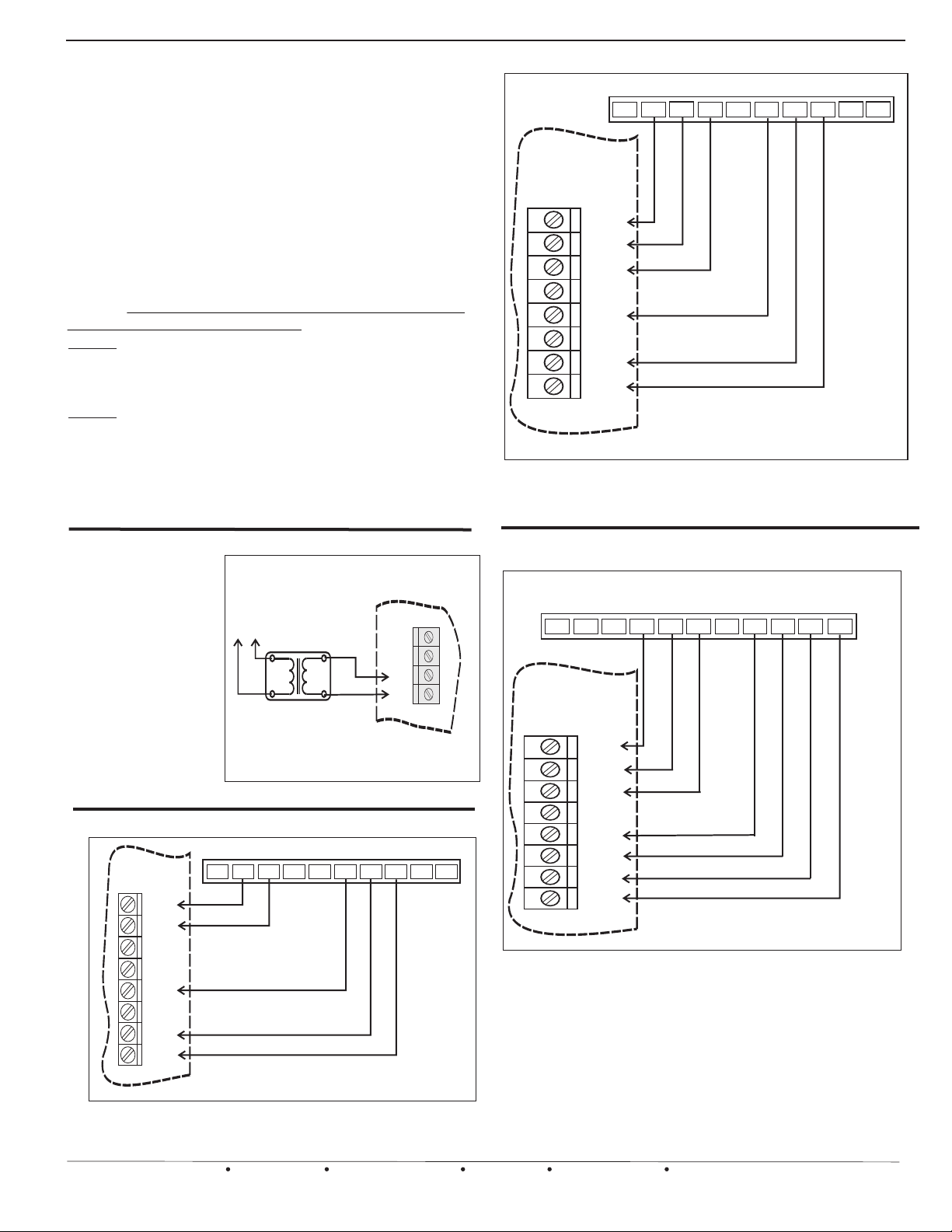
INSTALLATION INSTRUCTIONS and THERMOSTAT WIRING
Installation should be performed by qualified
personnel only. Follow local & national electrical &
mechanical codes. Use multi-conductor 18 awg solid
copper conductors. Wire number to number or letter to
letter on each control or device.
WARNING: THESE PANELS ARE DESIGNED FOR USE
WITH 24-30vac. DO NOT USE OTHER VOLTAGES! USE
CAU T I ON TO AVOID E L ECTR I C S H OCK O R
EQUIPMENT DAMAGE.
Mount the panel housing in a convenient location close to
the Air Handler. Mounting hardware is provided. Use the
knockouts provided on the panel housing as entryways
into the housing. Strain relief fittings can be used if
desired. Use care and do not damage the circuit board
when making wire connections.
NOTE: The 24 vac power required to operate a UZC4
system must be supplied by a separate transformer.
WARNING! DO NOT use the 24 vac power supply from
the HVAC manufacturer’s equipment.
NOTE: Unlike previous UZC series zone control
systems, the UZC4 supplies power to all connected
expansion modules. This improved design simplifies
the installation wiring and reduces the possibility of
polarity reversal or incorrect transformer phasing. The
UZC4 does allow you to isolate and power up the
damper terminal block separately for greater versatility.
CONVENTIONAL 2 HEAT / 1 COOL THERMOSTAT
MODEL EWT-3707
MODEL EWT-3707
W2
O
B
W1
C
*
ANY ZONE
T’STAT
C
W1/E
W2
O/B
Y1
Y2
R
G
Common wire not required if batteries are used.
*
Figure 4.
Model EWT-3707: Configured for typical 2 stage
Gas or Electric heating system with 1 stage
cooling.
Y1
R
G
L
E
POWER WIRING
Line
A single 24vac, 40va
UL Listed transformer
can power the UZC4
Main module with one
damper on each zone.
A total of four zones
and four dampers. See
page 19 for more load
and transformer data.
Voltage
PROVIDE
MEANS OF
DISCONNECT
TRANSFORMER
24vac, 40 - 100va
UL LISTED
Figure 2. UZC4 Power wiring Supply
TYPICAL 1 HEAT / 1 COOL THERMOSTAT WIRING
MODEL EWT-3707
ANY ZONE
T’STAT
B
C
W1/E
W2
O/B
Y1
Y2
R
G
Common wire not required if batteries are used.
*
Figure 3.
Model EWT-3707: Configured for 1 heat 1
cool (SS1 mode). Typical Gas, Oil or
Hydronic System.
EWC Controls Inc. 385 Highway 33 Englishtown, NJ 07726 800-446-3110 FAX 732-446-5362 E-Mail- [email protected]
MODEL EWT-3707
C
W1
W2
*
O
Y1
UZC4
Main Module
FA
FA
24 V
24 V
R - Hot
C - Common
R
E
G
R
C
L
CONVENTIONAL 2 HEAT / 2 COOL THERMOSTAT
TOUCHSCREEN THERMOSTAT
MODEL EWT-3102
R
S1
S2
L
C
W1
W2
E
Y1
Y2
G
*
ANY ZONE
T’STAT
C
W1/E
W2
O/B
Y1
Y2
R
G
Common wire not required if batteries are used.
*
Figure 5.
All of the preceding diagrams reflect conventional
(N on - He a t P u m p ) t h er m os t a t s, c on t ro l l i ng
conventional HVAC systems. However, the equipment
being controlled does not have to be the conventional
type. A heat pump system can be controlled using
conventional thermostats. But you cannot control a
conventional system using heat pump thermostats.
Model EWT-3102 : Configured for typical 2 stage
Gas or Electric heating system with 2 stage
cooling.
9
Page 10
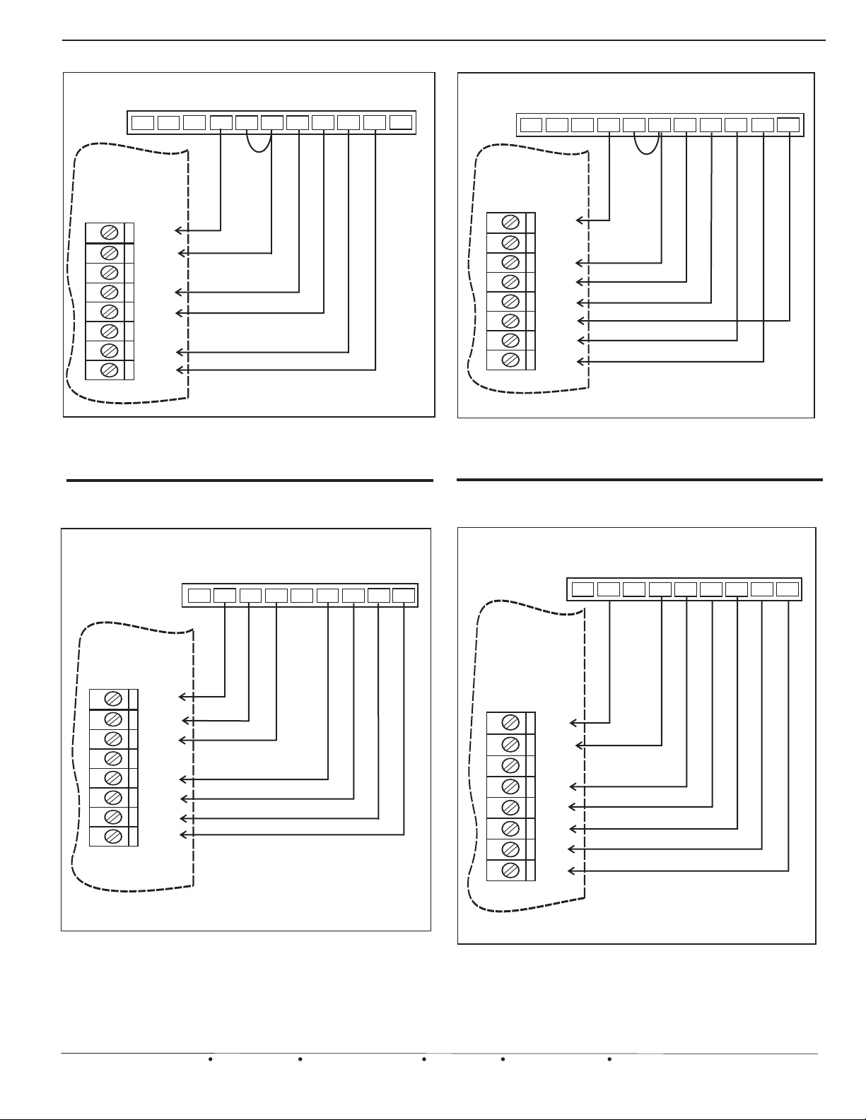
THERMOSTAT WIRING CONTINUED
ANY ZONE
T’STAT
Figure 6.
TOUCHSCREEN THERMOSTAT
MODEL EWT-3102
S1
S2
L
C
W2
E
O/B
Y1
R
Y2
G
*
**
C
W1/E
W2
O/B
Y1
Y2
R
G
Model EWT-3102: Configured for 2 heat 1 cool
heat pump (HP1 mode). See thermostat
instructions for further details.
Common wire not required if batteries are used.
*
Field installed jumper.
*
*
ANY ZONE
T’STAT
Figure 8.
TOUCHSCREEN THERMOSTAT
MODEL EWT-3102
S2
S1
L
C
W2
E
O/B
Y1
R
Y2
G
*
**
C
W1/E
W2
O/B
Y1
Y2
R
G
Common wire not required if batteries are used.
*
Field installed jumper.
*
*
Model EWT-3102: Configured for 3 heat 2 cool
heat pump (HP2 mode). See thermostat
instructions for further details.
WIRELESS THERMOSTAT: RECIEVER MODULE
MODEL EWT-3900
C
ANY ZONE
T’STAT
Figure 7.
B
C
W1/E
W2
O/B
Y1
Y2
R
G
Model EWT-3900: Wireless Thermostat.
O
Y2W1 W2 Y1
Configured for 2 heat 2 cool (MS2 mode).
See Thermostat instructions for further details.
WIRELESS THERMOSTAT: RECIEVER MODULE
MODEL EWT-3900
C
R
G
ANY ZONE
T’STAT
B
O
R
Y2W1 W2 Y1
G
C
W1/E
W2
O/B
Y1
Y2
R
G
Figure 9.
Model EWT-3900 Wireless Thermostat:
Configured for 3 heat 2 cool heat pump (HP2
Mode). See thermostat instructions for further
Details.
10
EWC Controls Inc. 385 Highway 33 Englishtown, NJ 07726 800-446-3110 FAX 732-446-5362 E-Mail- [email protected]
Page 11
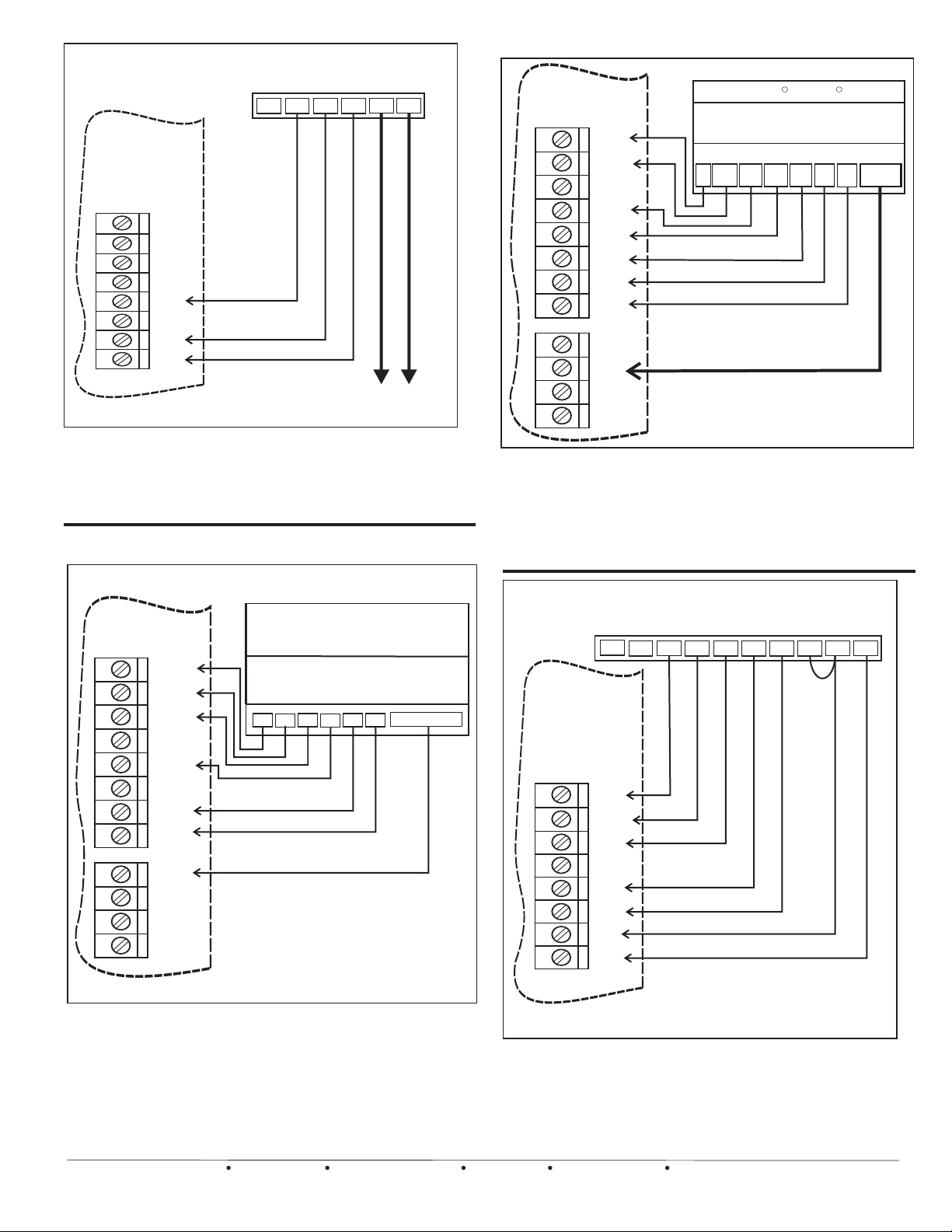
WIRING FOR RADIANT FLOOR HEAT
HEAT PUMP MODE WITH DE-HUMIDIFICATION
ANY ZONE
T’STAT
Figure 10.
MODEL EWT-3611
W
RH
G
C
W1/E
W2
O/B
Y1
Y2
R
G
C
RC
Y
To Radiant floor / Baseboard heat
zone valve or pump relay
Wiring a split circuit thermostat to operate a
Radiant floor heating or Baseboard heating
Hydronic system. The UZC4 controls the cooling
only, in this type of configuration.
WIRING FOR “ONE ZONE” MODE
ZONE 1
T'STAT
Figure 12.
C
W1/E
W2
R
Carrier Bryant
THERMIDISTAT
2 Heat 1 Cool HEAT PUMP
CONFIGURATION
Y1 / W2
O/W2
W / W1
C
Y / Y2
R
R
DHUM
G
O/B
Y1
Y2
R
G
ONE
ZONE
AUX R
CO2
CO2
Refer to Dehumidify
Operations on page 14.
Wiring for typical 2 stage Heat,1 stage cool Heat
Pump. Diagram reflects De-humidification
terminal wired to the Auxilary input. For auxilary
output wiring see page 14. Auxilary Relay Dip
Switch #5, Bank #2, should be set to Reverse
Acting. (RA)
ZONE 1
T'STAT
Figure 11.
Commercial Grade
Thermostat
C
W1/E
W2
O/B
Y1
Y2
R
G
ONE
ZONE
AUX R
CO2
CO2
Wiring for automatic activation of “One Zone”
mode using a commercial grade thermostat in
Zone 1. Program or wire the thermostat to Energize
(close contact) the One Zone Terminal and setback
the temperature when the building is
Unoccupied....When the building is Occupied, the
thermostat will de-energize (open contact) the One
Zone Terminal.
ZONE THERMOSTAT
#1
UNOCC / OCC
C
W2W1
RY
G
ANY ZONE
T’STAT
Figure 13.
MODEL IZT-250
INTERNET THERMOSTAT
O
CB
W1 W2
Y1
Y2
RC
RH
G
C
W1/E
W2
O/B
Y1
Y2
R
G
Model IZT-250 Internet Thermostat:
Configured for 2 heat 2 cool. See thermostat
instructions for further details.
EWC Controls Inc. 385 Highway 33 Englishtown, NJ 07726 800-446-3110 FAX 732-446-5362 E-Mail- [email protected]
11
Page 12
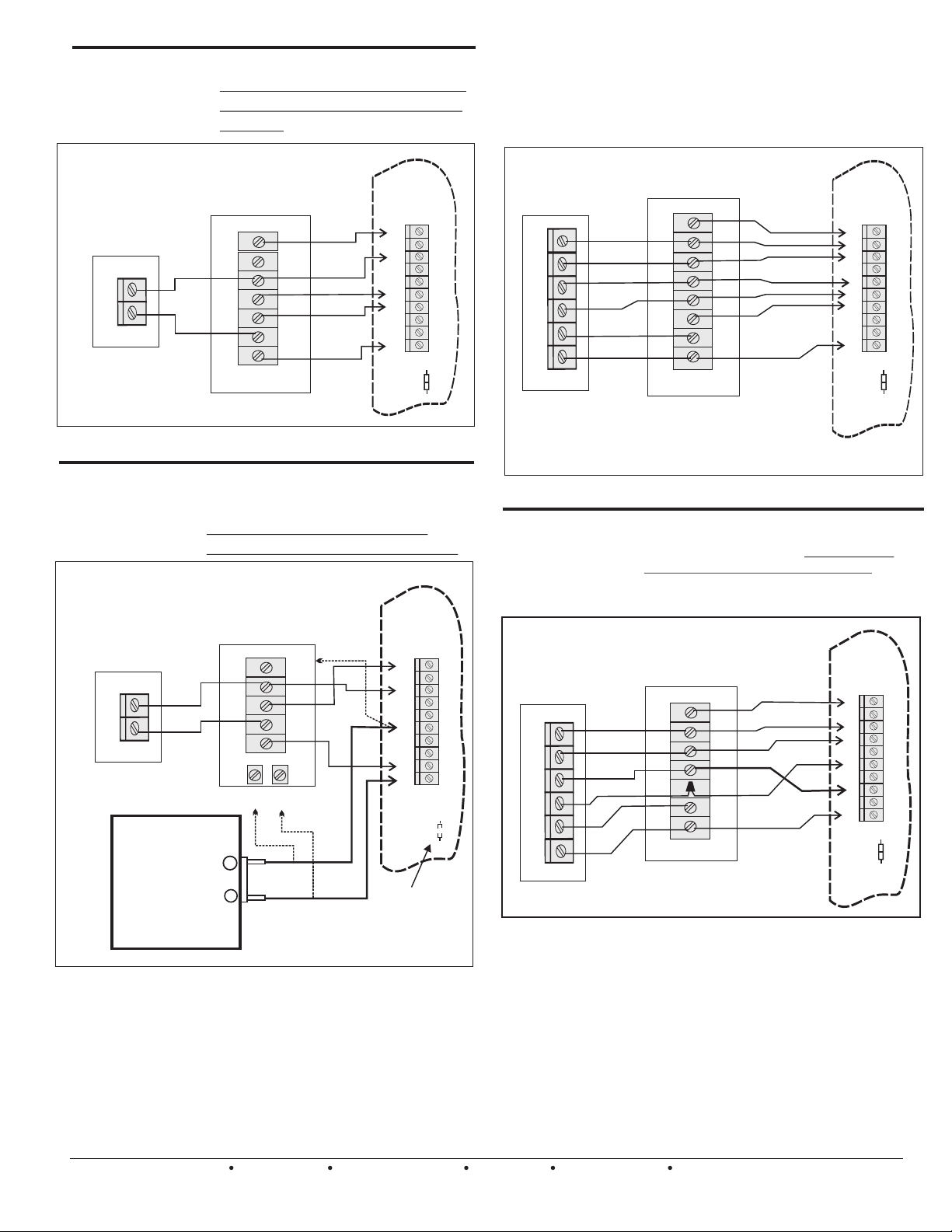
HVAC SYSTEM WIRING
Single
Transformer
Gas/Oil Systems
1 or 2 Stage Heat
OUTDOOR
CONDENSING
UNIT
Y
C
Figure 14. Single transformer Gas / A/C system.
Typical gas / oil system with A/C.
A jumper wire between Rc and Rh is
provided. There is no need to install
a jumper.
GAS/OIL
Furnace
1or2 STAGE
G
Y2
Y1
W1
W2
C
R
UZC4
G
Y2
Y1
O
B
W1
W2
E
RC
RH
RC/RH
LINK
Conventional 4
Stage Heat Pump
with a “B” Type
Reversing Valve
Typical heat pump system wiring with
electric resistance backup heat. Wire
up the reversing valve to either O or B,
depending on your system type.
Applies to air cooled or geothermal /
ground source systems.
AIR HANDLER
WITH 1 0R 2 STAGE
ELECTRIC RESISTANCE
HEAT PUMP
2 STAGE
H
V
A
C
S
Y
S
T
E
M
Y2
Y
B
X / W
C
R
Diagram reflects a Heat Pump with a “B” type
Reversing Valve NOT a neutral or Common
terminal designated as “B”.
BACKUP HEAT
G
Y2
Y
B
W
W2
C
R
UZC4
G
Y2
Y1
O
B
W1
W2
E
RC
RH
RC/RH
LINK
H
V
A
C
S
Y
S
T
E
M
Two
Transformer
Oil/ Hydro
Systems
OUTDOOR
CONDENSING
UNIT
Y
C
Oil / Wood Burner
Primary Control
Boiler Control
Zone Valve
Pump Control
Terminals
Wiring diagram for a typical oil burner,
hydronic zone / Air handler with A/C.
Cut the Rc / Rh link on the UZC4
Panel for systems requiring isolation.
TYPICAL FAN
CENTER
TERMINAL
*W
BLOCK
W*
Y
G
C
R
*
TT
ISOLATION TERMINALS
OR WIRES
*
or
or
or
T
T
UZC4
G
H
Y2
V
A
Y1
C
O
-
B
S
W1
Y
W2
S
T
E
E
RC
M
RH
RC/RH
LINK
*
Cut Rc/Rh
Jumper
Figure 15. Two transformer Oil or Hydronic / A/C system.
* Note: Your Air Handler may include a W terminal. That
means it may have it’s own isolation circuit. If you can
confirm this, simply connect the W1 terminal to the W
terminal on the air handler. Do not cut the Rc / Rh jumper.
Wire up your Oil Burner, Pump Control, or Hydronic Zone
valve to the isolation terminals or wires provided in the air
handler. (follow dashed lines)The fan is controlled via
time delay relay inside the air handler, or set the UZC4
“FAN “ Dip Switch to the “HYDRO” position.
12
EWC Controls Inc. 385 Highway 33 Englishtown, NJ 07726 800-446-3110 FAX 732-446-5362 E-Mail- [email protected]
Figure 16. Conventional Heat Pump System
Dual Fuel
Heat Pump
with “O” Type
Reversing Valve
HEAT PUMP
1 STAGE
Y
O
Wout
W
C
R
Hi Efficiency Heat Pump with built-in Outside
Air Changeover Capability. The Heat Pump
makes the decision to run the Furnace. Note
that the UZC4 can still operate the furnace in
Emergency Mode!
GAS OR OIL
FORCED AIR
FURNACE
BACKUP HEAT
G
Y
O
W
C
R
UZC4
G
Y2
Y1
O
B
W1
W2
E
RC
RH
RC/RH
LINK
H
V
A
C
S
Y
S
T
E
M
Figure 17. Single stage heat pump and single stage furnace.
Note that a Conventional & Dual fuel heat pump could wire up more or less the
same. The difference is how staged heat operates. In a Conventional system,
the indoor fan & the compressor continues to run when stage up occurs. In a
Dual Fuel system, the indoor fan & the compressor shuts down when stage up
occurs. The UZC4 will perform these functions automatically. All you have to
do is set the dip switches to the correct settings. Select DF or CONV at dip
switch #2, Bank 1. Choose to activate 2nd stage heat by TIMER or by
OUTSIDE AIR TEMPERATURE. (Optional Sensor Required) You can also
use Multi-stage thermostats in any or all Zones. When the thermostat stage up
heat demand is satisfied, the UZC4 will stage down, unless DF/OAS has been
selected and the outdoor temperature is lower than the OAS changeover
setting. In that case the system will continue in FUEL mode, until all heating
demands are fully satisfied. Your Heat Pump may be capable of making
these decisions without the aid of the UZC4, in which case you may elect
to wire your system as shown in figure 17.
Page 13
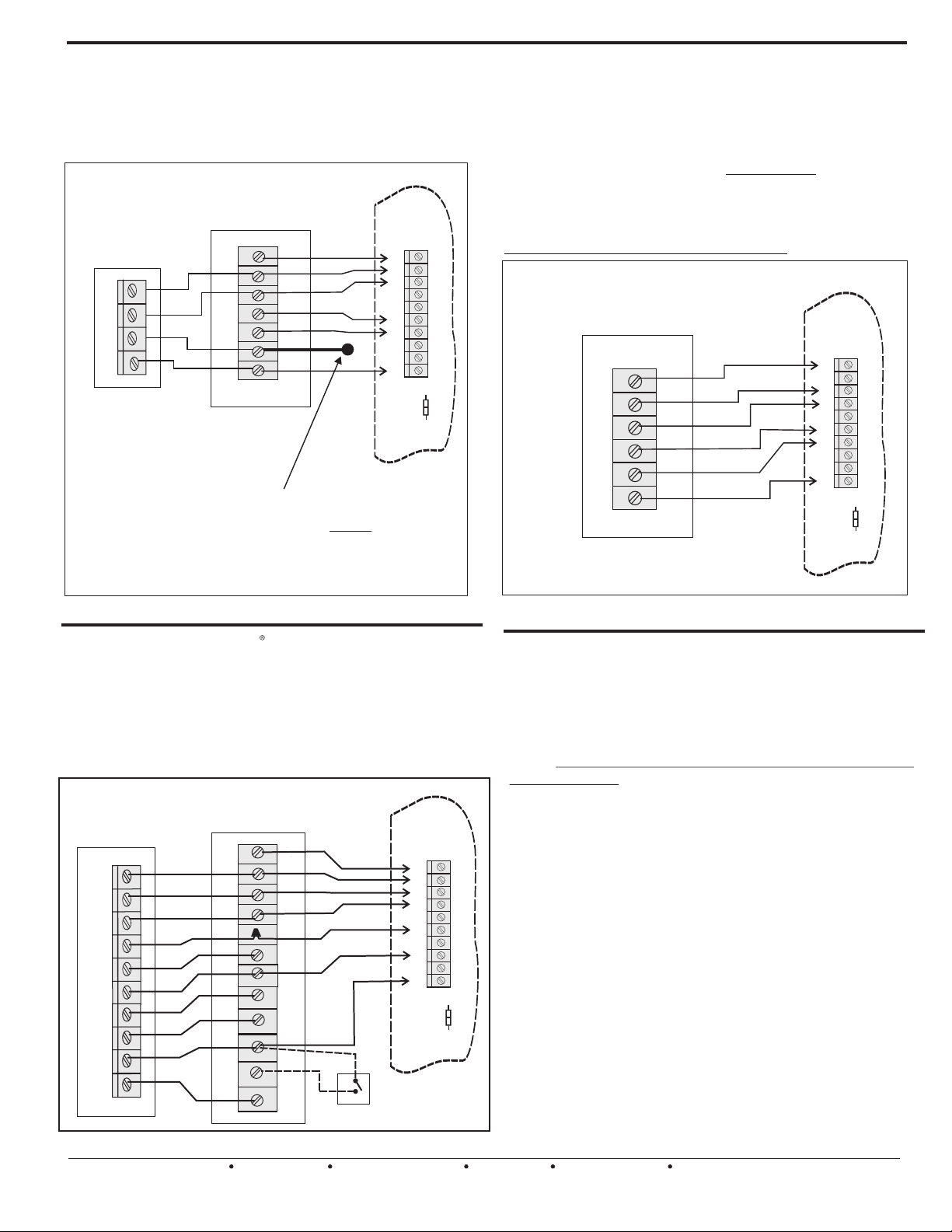
SYSTEM WIRING CONTINUED
Typical A/C
Split System
2 stage heat
2 stage cool
Typical 2 stage gas or straight electric
furnace with 2 stage cooling. Choose
“Timer” or “Outside Air Sensor” to delay
2nd stage, or use 2 stage T-stats on all
zones.
2 STAGE
OUTDOOR
CONDENSING
UNIT
Y2
Y1
C
R
* “R” wire may
not be required
on your Outdoor
Condensing Unit
2 STAGE GAS
FURNACE
G
Y2
Y1
W1
W2
C
R
*
G
Y2
Y1
W1
W2
C
R
UZC4
G
Y2
Y1
O
B
W1
W2
E
RC
RH
RC/RH
LINK
H
V
A
C
S
Y
S
T
E
M
Note that you can route a Common wire back to the
“System” terminal block, but it should never be
connected! Use it as a TEST point while
troubleshooting. It should be marked as such and remain
capped off when not in use!
HVAC system with OEM Voltage Control Circuitry
Some HVAC manufacturers are designing HVAC Systems
with 5 - 18 vdc control circuits. Standard 24 vac thermostats
will not work on these systems. These systems can only be
controlled with their own thermostat. But the SYSTEM
connections on a UZC4 are all dry contacts! Virtually any
HVAC low voltage control circuit can be connected and
controlled. All you have to do is ask the manufacturer which
numbered terminals correspond to the standard terminals.
Theoretical diagram only shown below.
OEM Geothermal or Ground Source
Packaged Heat Pump. 3 stage heat &
1 stage cool with “O” type reversing valve.
UZC4
G
6
5
4
3
2
1
Y2
Y1
O
B
W1
W2
E
RC
RH
RC/RH
LINK
H
V
A
C
S
Y
S
T
E
M
Figure 18. Single transformer 2 Stage Heat / AC system
High Efficiency
Heat Pump.
3 or 4 Stage Heat
and 2 Stage Cool
High Efficiency
HEAT PUMP
2 STAGE
Y2
Y1
O
W
C
W1 Out
W2 Out
Y2 Out
R
X/L
LUXAIRE High Efficiency “Acclimate” Heat
Pump System. Refer to Mfr’s data for
specific equipment dip switch settings and
logical program settings. Set up the UZC4 to
control the staging based on “Time” with
single stage Conventional Thermostats. Or
you can install 3 stage Heat Pump
Thermostats on all zones.
Variable Speed
FURNACE OR AIR HANDLER
WITH 1 0R 2 STAGE
BACKUP HEAT
UZC4
G
Y2
Y1
O
C
W/W1
W2
Y2/Y
R
HUM
X/L
G
Y2
Y1
O
B
W1
W2
E
RC
RH
RC/RH
LINK
Optional Humidistat
See Mfr’s Data
Figure 19. 3 or 4 Stage High Efficiency Heat Pump System
EWC Controls Inc. 385 Highway 33 Englishtown, NJ 07726 800-446-3110 FAX 732-446-5362 E-Mail- [email protected]
Figure 20. OEM system with 5 - 18 vdc control circuit.
IMPORTANT NOTES:
HEAT PUMP EMERGENCY OPERATIONS:
Any Thermostat can demand Emergency Mode!
When emergency mode is activated, the UZC4 will
energize the “E” output terminal and the “W1” terminal.
The “W2” terminal will also energize after a 3 minute
delay. There is no need to jumper the “E” terminal to the
“W” terminals. The UZC4 does this to ensure that the
Emergency backup system energizes, regardless of
which terminal it is connected to. In fact, the design of
the UZC4 encourages you to separate up to three (3)
electric strip banks, preventing large in-rush currents
H
V
A
C
S
Y
S
T
E
M
when all banks are tied together. This will also reserve at
least one bank dedicated for Emergency mode and Dehumidify/Reheat operations .
Make sure that you have correctly selected either “Dual
Fuel” or “Conventional” Heat Pump to obtain the proper
staging operations for your particular system.
Warning:
All of the wiring diagrams provided are general in
nature and may not perfectly match your particular
application. This is due to differences in the HVAC
Mfr’s terminal designations and functions!
Variations on these diagrams and other System or
Thermostat applications are available b y
contacting the EWC Technical Support Hotline, or
visit our web site at www.ewccontrols.com
13
Page 14
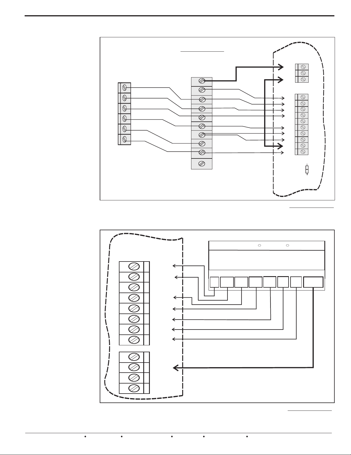
SYSTEM WIRING CONTINUED - Specialty Applications
The Auxiliary Feature
can be used to
activate DeHumidify
Operations on
Variable or Constant
Speed HVAC Systems.
The UZC4 can be set up
to control DeHumidify
operations on most any
H e a t P u m p o r
Con ven t ion al H VAC
system. The UZC4 will
also activate a unique
De hu mi di fy C o n tr ol
Algorithm when the Dehumidify demand is
d e t e c t e d . W h e n a
separate control calls for
Dehumidification, the
UZC4 will activate “Y1”,
“G” and the Auxiliary
Relay, to signal the Air
Handler to slow the fan
down.
The UZC4 WILL ALSO
e n e r g i z e t h e ( E )
E m e r g e n c y o u t p u t
terminal to REHEAT the
cold discharge air and
Rapidly Dehumidify the
home. Energizing the
“E” during this cycle
prevents over-cooling
the home. A common
Customer complaint with
the DeHumidify cycle in
these HVAC systems.
NOTE1: The UZC4 will
n o t a c t i v a t e
dehumidify operations
unless the “Y1” (cool)
signal is also detected
at Zone 1.
NOTE2: A cooling or
h e a t i n g d e m a n d
detected at any other
zone can cause a delay
to activate or will
te rm in a te th e D eHumidify operations.
NOTE3: Dehumidify can
only be achieved In (RA)
Reverse acting mode.
14
EWC Controls Inc. 385 Highway 33 Englishtown, NJ 07726 800-446-3110 FAX 732-446-5362 E-Mail- [email protected]
Using the UZC4’s Auxiliary Feature to control Dehumidify Operations
Variable Speed
AIR HANDLER
with 1 or 2 stage Heat
1 or 2 STAGE
HEAT PUMP
Y2
Y1
O
W
C
R
Figure 21.
Wiring for typical 4 stage Heat,2 stage cool Heat Pump. Diagram reflects De-humidification
terminal wired to the Auxiliary output (NC) Normally Closed terminal. Auxiliary Relay Dip
Switch #5, Bank #2, should be set to (RA) Reverse Acting when using the type of control
shown below.
ZONE 1
T'STAT
C
AND
DEHUMIDIFICATION
CAPABILITY
DH
G
Y2
Y1
O
W1
W2
C
R
HUM
THERMIDISTAT
3 Heat 2 Cool HEAT PUMP
CONFIGURATION
Carrier Bryant
R
UZC4
NC
NO
C
G
Y2
Y1
O
B
W1
W2
E
RC
RH
RC/RH
LINK
R
A
U
X
R
L
Y
H
V
A
C
S
Y
S
T
E
M
W1/E
W2
C
W / W1
O/W2
Y1 / W2
Y / Y2
R
G
DHUM
O/B
Y1
Y2
R
G
ONE
ZONE
AUX R
CO2
This type of control uses (RA) reverse acting
logic to signal De-humidify demands.
CO2
Figure 22.
Wiring for typical 3 stage Heat,2stage cool Heat Pump. Diagram reflects De-humidification
terminal wired to the Auxiliary input. Auxiliary Relay Dip Switch #5, Bank #2, should be set
to (RA) Reverse Acting. Contact EWC Controls Technical support or visit our web site for
additional diagrams and alternate control methods to achieve De-humidification.
Page 15
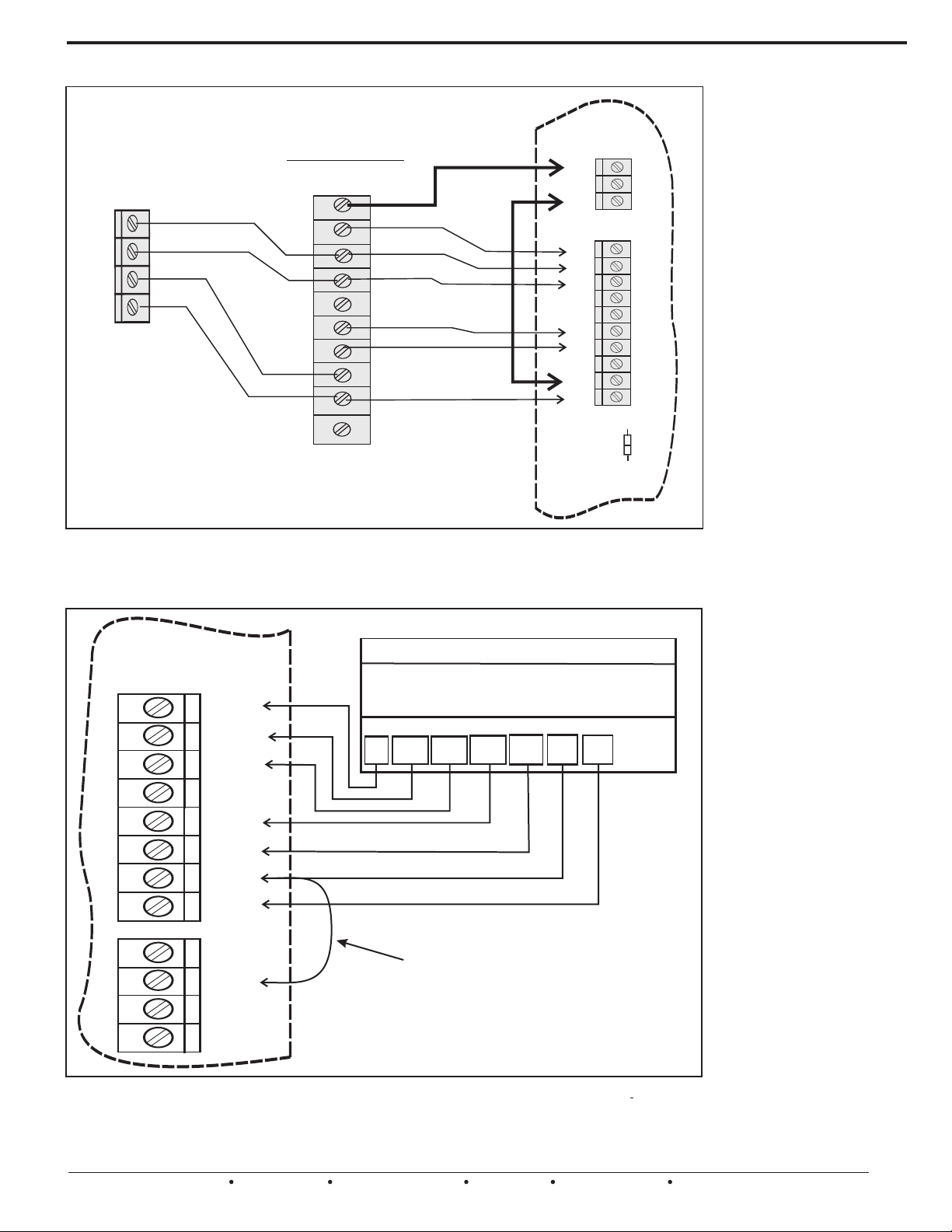
SYSTEM WIRING CONTINUED - Specialty Applications
Using the UZC4’s Auxiliary Feature to control Fan Speed
UZC4
Variable Speed
1 or
2 STAGE
CONDENSOR
Y2
Y1
C
R
FURNACE
with 1 or 2 stage Heat
DS/BK
G
Y2
Y1
O
W1
W2
C
R
HUM
NC
NO
C
G
Y2
Y1
O
B
W1
W2
E
RC
RH
RC/RH
LINK
Figure 23.
Wiring for typical 2 stage Heat,2 stage cool Gas Furnace.. Diagram reflects DS/BK terminal
wired to the Auxiliary output (NC) Normally Closed terminal. Auxiliary Relay Dip Switch #5,
Bank #2, should be set to (RA) Reverse Acting when using the type of control shown.
A
U
X
R
L
Y
H
V
A
C
S
Y
S
T
E
M
ZONE 1
T'STAT
C
W1/E
W2
C
2 Heat 2 Cool
Thermostat
W1
W2
Y1
Y2
R
G
The Auxiliary Feature
can also be used to
Control the Fan speed
based on the Number
of Zones calling.
The UZC4 can be set up
to control the fan speed
on most any variable
speed air handlers or
furnaces during cooling
operations. The UZC4
will lower the fan speed
when 25% or less of the
total zones are calling
for cooling. When this
occurs the UZC4 will
activate the Auxiliary
relay output which will
de-energize the DS/BK
terminal on the Forced
air unit resulting in the
blower running at a
lower speed.
NOTE 1: A jumper is
required across the R
terminal on zone 1 and
the AUX R terminal.
N O T E 2 : O t h e r
conf igura tions are
available. Contact
Technical Support for
further information.
O/B
Y1
Y2
R
G
ONE
ZONE
AUX R
JUMPER
REQUIRED
CO2
CO2
Figure 24.
Wiring for typical 2 stage Heat, 2 stage cool Thermostat. Diagram reflects AUX R terminal
wired with a jumper to the R terminal. Auxiliary Relay Dip Switch #5, Bank #2, should be
set to (RA) Reverse Acting.
EWC Controls Inc. 385 Highway 33 Englishtown, NJ 07726 800-446-3110 FAX 732-446-5362 E-Mail- [email protected]
15
Page 16
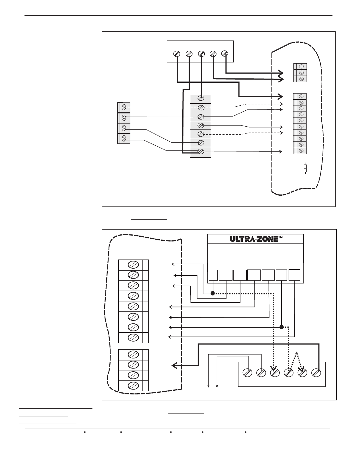
SYSTEM WIRING CONTINUED - Specialty Applications
The Auxiliary Feature
can be used to control
Humidify Operations
on any HVAC System.
Set the Auxiliary relay
Dip Switch to Direct
Acting and connect a dry
contact Humidity Control
to the “R” and “AUX R”
terminals.
When the UZC4 detects
a demand to Humidify, it
w i l l e n e r g i z e t h e
Auxiliary Output Relay.
The Au xil i ary rel a y
contacts are dry, so you
can connect and control
most any humidifier you
want.
These drawings show
an Ultra-Zone 072000
Smart
Humidistat connected to
the Auxiliary Input, and
an S2000/S2020 Steam
Humidifier connected to
the Auxiliary Output.
Refer to the Technical
Bulletins on the UltraZone S2000/S2020 and
t he 0 7 2 00 0 S m a r t
Humidistat for additional
details.
The UZC4 humidit y
control logic allows a
Humidity demand to
occur at any time. There
is no need for a Heating
demand to occur first.
Bear this in mind when
field wiring your system.
Yo u m a y h a v e t o
interlock your Humidifier
to run during a heating
c a l l o n l y ! S t e a m
Humidifiers can run at
any time and do not
r e q u i r e a h e a t i n g
demand to occur first.
N O T E : H u m i d i f y
operations can only be
achieved in (DA)
Direct acting mode.
16
EWC Controls Inc. 385 Highway 33 Englishtown, NJ 07726 800-446-3110 FAX 732-446-5362 E-Mail- [email protected]
Using the UZC4’s Auxiliary Feature to control Humidify Operations
S2000/S2020 STEAM HUMIDIFIER
RG1 G2 H H
UZC4
NC
NO
2 STAGE
1 or
CONDENSING
UNIT
G
Y2
Y1
C
R
“R” WIRE MAY NOT
BE REQUIRED ON
YOUR CONDENSING
UNIT!
Figure 25.
Wiring for typical 2 stage Heat,2 stage cool conventional HVAC System. Diagram
reflects Humidification terminal wired to the Auxiliary output (NO) Normally Open
terminal. Auxiliary Relay Dip Switch #5, Bank #2, should be set to Direct Acting. (DA)
ZONE 1
T'STAT
Variable or Constant Speed
with 1 or 2 stage HEAT
1 or 2 stage COOL
C
W1/E
Y2
Y1
W1
W2
C
R
FURNACE
and
C
2 Heat 2 Cool
CONFIGURATION
Y1
W1
W2
Y2
C
G
Y2
Y1
O
B
W1
W2
E
RC
RH
RC/RH
LINK
R
G
A
U
X
R
L
Y
H
V
A
C
S
Y
S
T
E
M
W2
O/B
Y1
Y2
R
G
ONE
ZONE
AUX R
CO2
CO2
Figure 26.
Wiring for typical 2 stage Heat,2 stage cool Conventional HVAC System. Diagram
reflects a Direct Acting Humidification control wired to the Auxiliary input.
Dip Switch #5, Bank #2, should be set to Direct Acting. (DA) Refer to the Ultra-Zone
072000 Tech. Bulletin.
To OAS
OD OD C R H H
Ultra-Zone 072000 HUMIDISTAT
Auxiliary Relay
Page 17
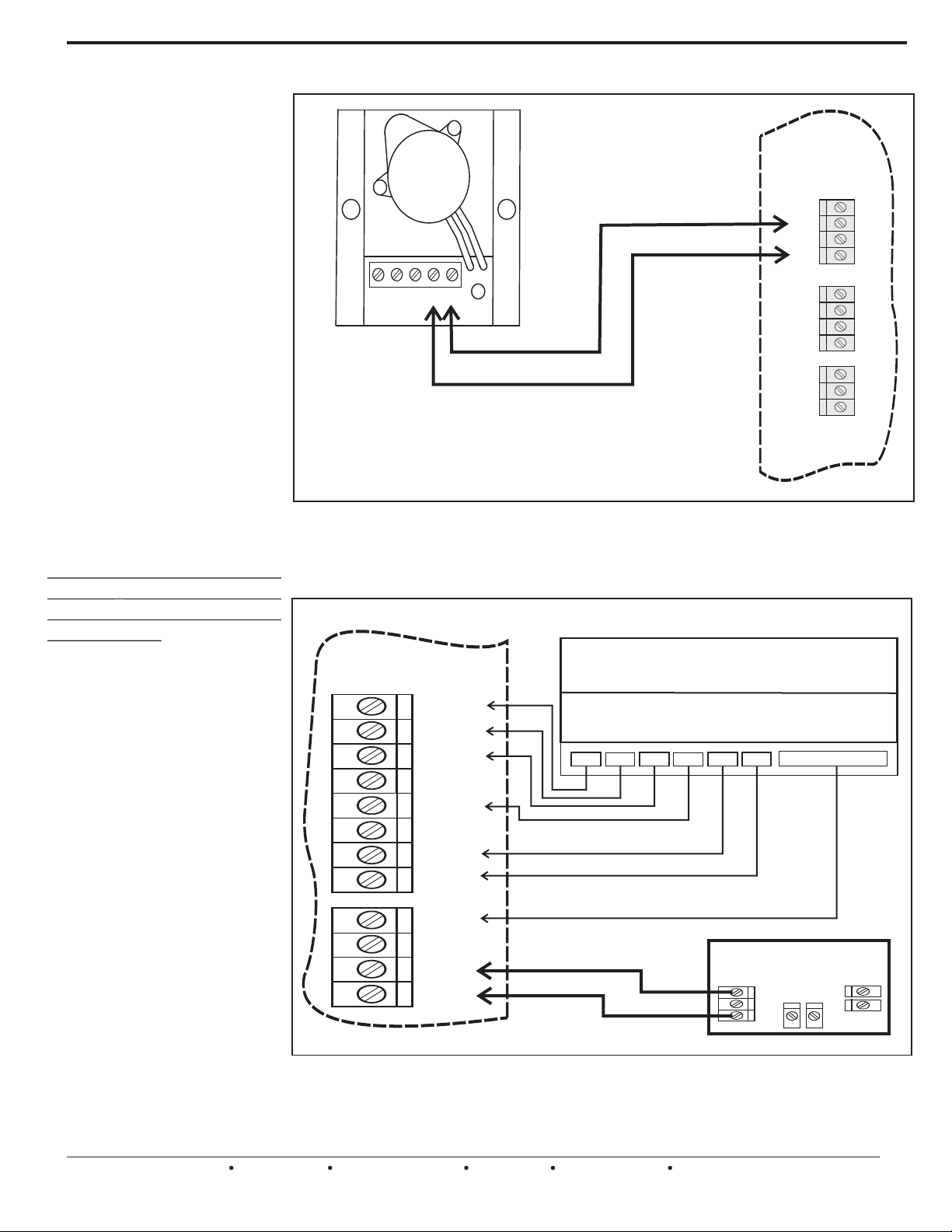
SYSTEM WIRING CONTINUED - Specialty Applications
The UZC4 features a CO2
Monitoring interlock system
that will activate a Fresh Air
Damper and the indoor Fan
on the HVAC system in
response to a Separate CO2
Mon itor. Thi s po w erfu l
feature allows Demand
Based Ventilation of a large
h o m e o r c o m m e r c i a l
building, based on the daily
occupancy levels. Demand
Based Ventilation saves
energy, reduces overventilation, and optimizes
air quality in the building.
Wire up the UZC4 to a
separate CO2 Monitor with
auxilary dry contacts as
shown. Also install and wire
up a fresh air damper as
shown.
Set the PPM trip threshold on
the CO2 Monitor per the
Mfr’s. Instructions or local
requirements.
Upon activation, the UZC4
will open the Fresh Air
Damper and Start the Indoor
Fan if it is not already
running. The UZC4 will
continue the ventilation
process, until the CO2
Mo n it or r e s et s. O th er
devices can be connected to
the CO2 terminals such as a
Clock Timer, Manual Switch
or Enthalpy Control.
NOTE: Cooling & Heating
operations are not affected
by activation of this feature.
NOTE: Activation of the Fire
Alarm Interlock Feature will
over-ride (shutdown) the
fresh air ventilation process.
Using the UZC4’s CO2 Feature to satisfy Building Fresh Air Ventilation Codes
EWC Controls
Spring Return
Motor Actuator
MA-ESR
NC NO C M M
This Damper Actuator is wired to
Power OPEN and Spring CLOSE
UZC4
M6
M4
M2
M1
M6
M4
M2
M1
NC
NO
C
O
A
D
M
P
R
E
B
D
A
U
X
R
L
Y
Power OPEN & Power CLOSE
Figure 27.
This diagram reflects the UZC4 OA DMPR Output terminals wired to an UltraZone
Spring Closed type damper. When the UZC4 detects a Ventilation Demand, it will
energize the damper open and force the Indoor Fan to run. The UZC4 will stay in this
mode until the CO2 Monitor detects an acceptable CO2 level in the building.
ZONE 1
T'STAT
Figure 28.
This diagram reflects the UZC4 CO2 terminals wired to the (NO) normally open contacts
of a third party device. The circuit is normally open and the contacts must close to
activate this feature. This feature operates regardless of all other functions except the
FIRE Mode interlock.
dampers can also be used.
Commercial Grade
C
W1/E
W2
O/B
Y1
Y2
R
G
ONE
ZONE
AUX R
CO2
CO2
ZONE THERMOSTAT
#1
C
Thermostat
RY
W2W1
G
CO2 Monitor
C
NC
NO
UNOCC / OCC
EWC Controls Inc. 385 Highway 33 Englishtown, NJ 07726 800-446-3110 FAX 732-446-5362 E-Mail- [email protected]
17
Page 18
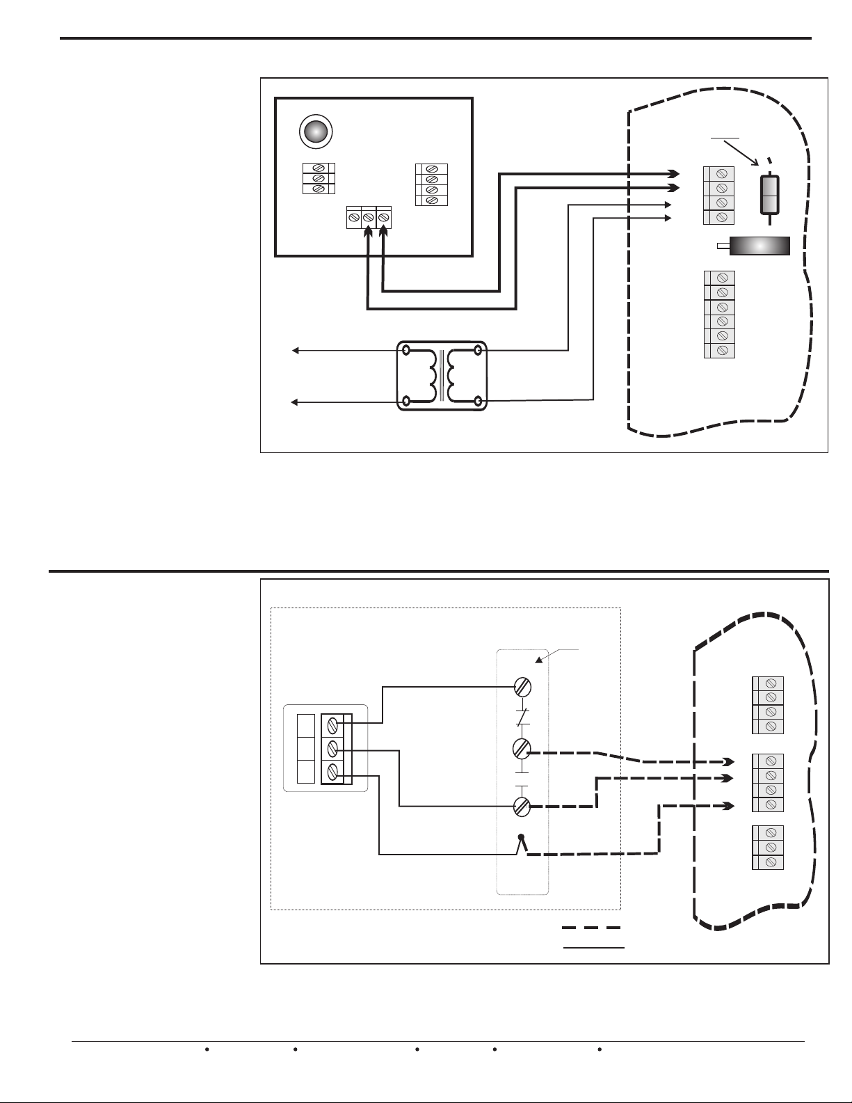
SYSTEM WIRING CONTINUED - Specialty Applications
The UZC4 has a “FIRE”
interlock feature that allows
the UZC4 to satisfy HVAC Fire
Co de i n Re si de nt ia l &
C o m m e r c i a l b u i l d i n g s .
Coordinate with the Fire
S y s te m s Co n t r ac t o r t o
interlock the UZC4 into the
building Fire Alarm system as
shown and cut the Jumper 1.
When properly interlocked to
the buildings Fire A larm
system, the UZC4 becomes
an integral part of the Fire
Safety System. If the Fire
Alarm system activates, the
UZC4 will shutdown the
controlled HVAC system and
force all connected dampers to
t h e c l o s e d p o s i t io n s ,
effectively isolating the duct
work and the Fan system.
This action will reduce the
spread of smoke advancing
through the building assisted
by Fan and Duct systems that
are not interlocked with a Fire
Alarm system, or equipped
with the capability to do so.
Using the UZC4’s “FIRE Interlock” Feature to satisfy Building Fire Codes
UZC4
FIRE ALARM
SYSTEM
CUT
JMP1
FA
NC C NO
To Line Voltage
Provide over current
protection
Separate 24vac
Figure 29.
Transformer
This diagram reflects the UZC4 Fire Alarm Output terminals wired to a FIRE ALARM
System with a Fail Safe, Normally Open Dry Contact. The circuit is normally closed and
must OPEN to activate the UZC4 FIRE MODE. Be sure to cut the Jumper 1 resistor when
you interlock the UZC4 to the Fire Alarm System. When the UZC4 activates Fire Mode,
the HVAC System will shutdown and all connected dampers will close to Isolate &
Compartmentalize the HVAC Duct System. The Fire Alarm System must reset to NORMAL
before the UZC4 will allow HVAC Operations to resume.
FA
24V
24V
RESET
MXR
MXC
M6
M4
M2
M1
R
C
CB1
The UZC4 has a set of
dedicated terminals to power
up and control an (EBD)
Electronic Bypass Damper.
The UZC4 will assume control
of the EBD and force it to the
OPEN position during the Idle
periods, Short cycle delays or
Changeover delays. It will also
maintain that open position for
45 seconds at the start of any
th er mo st at d em an d fo r
Heating, Cooling, or Fan only
operation. After 45 seconds
the UZC4 will release control
of the EBD, resulting in a
smooth gradual increase in
static pressure. The 45 second
st ar t u p d el ay al lo ws a
Constant speed fan to start in a
“Quiet Mode” eliminating air
noise upon system startup. It
also eliminates hunting on
variable speed systems and it
enhances the latent cooling
capacity of any HVAC system.
18
EWC Controls Inc. 385 Highway 33 Englishtown, NJ 07726 800-446-3110 FAX 732-446-5362 E-Mail- [email protected]
Using the UZC4’s “ON BOARD BYPASS DAMPER SUPPORT”
“EBD” Motor
6
4
1
Pressure Control
Wiring Compartment
RED
GREEN
WHITE “COMMON” WIRE
NC
C
NO
WIRE
NUT
UZC4
M6
M4
M2
M1
M6
M4
M2
M1
NC
NO
C
O
A
D
M
P
R
E
B
D
A
U
X
R
L
Y
Field Wiring =
Figure 30.
Wire up the “EBD” straight to the UZC4 to obtain integrated Bypass Damper operational
support via the UZC4’s bypass firmware. The UZC4 defaults the bypass damper open
during idle periods and releases control to the EBD 45 seconds after the Fan starts. This
action results in a smooth, quiet startup and gradual increase in static pressure.
Factory Wiring =
Page 19
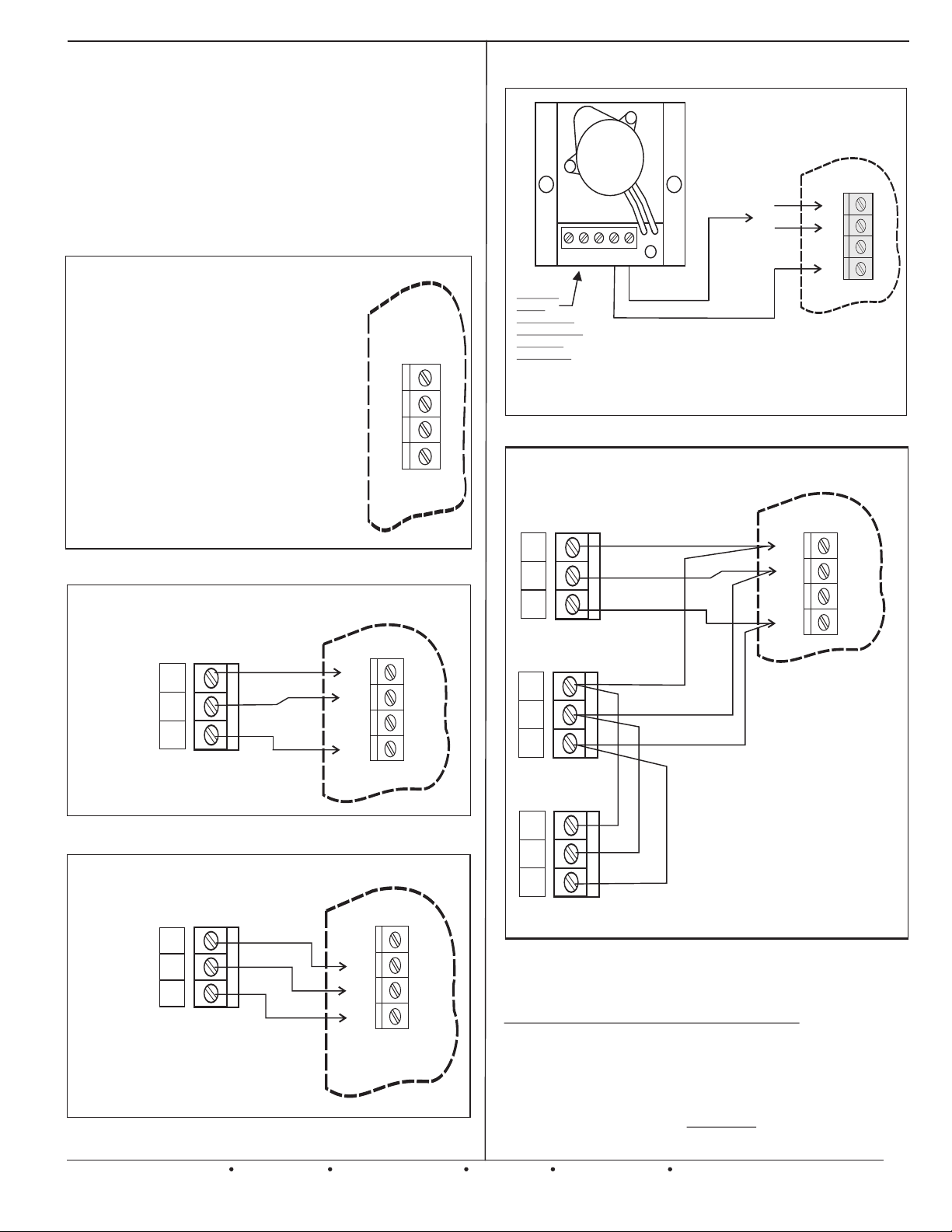
DAMPER WIRING AND CONFIGURATION
Note: All zone dampers default to the "OPEN"
position after a purge delay has occurred.
Dampers also default “OPEN” during
changeover & short cycle delays, and when
all zone demands are satisfied, and no
signals are detected from the thermostats.
REFERENCE THESE DIAGRAMS PRIOR TO
INSTALLATION AND POWER WIRING. DOING SO WILL
SAVE TIME AND LABOR ON THE JOB SITE.
ZONE MODULE DAMPER
MOTOR TERMINAL BLOCK
DESIGNATION & FUNCTION
Terminal M6
Terminal M4
Terminal M2
Terminal M1
24vac to Close a damper(s)
24vac to Open a damper(s)
Constant 24vac HOT
Common 24vac
M6
M4
M2
M1
Z
O
N
E
2 Wire Spring Return Motor Wiring
EWC Controls
Spring Return Motor Wiring
MA-ESR
Either one
Not both
NC NO C M M
Auxilary
SPDT
End Switch
Dry Contacts
Rated for
24vac only
A Spring Open Damper is wired to M1 & M6
A Spring Close Damper is wired to M1 & M4
Figure 34.
Multiple MA-ND & MA-URD
Damper Wiring on a Single Zone
.
{
M6
M4
M2
M1
Z
O
N
E
.
Figure 31.
All Models MA-ND & MA-URD Damper Wiring
6
4
1
Patented Optical
Damper Motor Actuators
Figure 32.
M6
M4
M2
M1
Z
O
N
E
All Models SMDL & BMDL Damper Wiring
4
2
1
Patented Optical
Damper Motor Actuators
Figure 33.
EWC Controls Inc. 385 Highway 33 Englishtown, NJ 07726 800-446-3110 FAX 732-446-5362 E-Mail- [email protected]
M6
M4
M2
M1
Z
O
N
E
6
4
1
M6
M4
M2
M1
Z
O
N
E
6
4
1
Multiple dampers
wired to operate
6
4
together on a single
zone
1
Figure 35.
On all these dampers and most older style
dampers, including competitor’s dampers,
always wire up number to number.
Contact EWC Controls Technical Support
when you are on the job site for assistance
with damper wiring.
NOTE: Some older style dampers cannot be
wired in parallel. Do not overload your
transformer!
19
Page 20
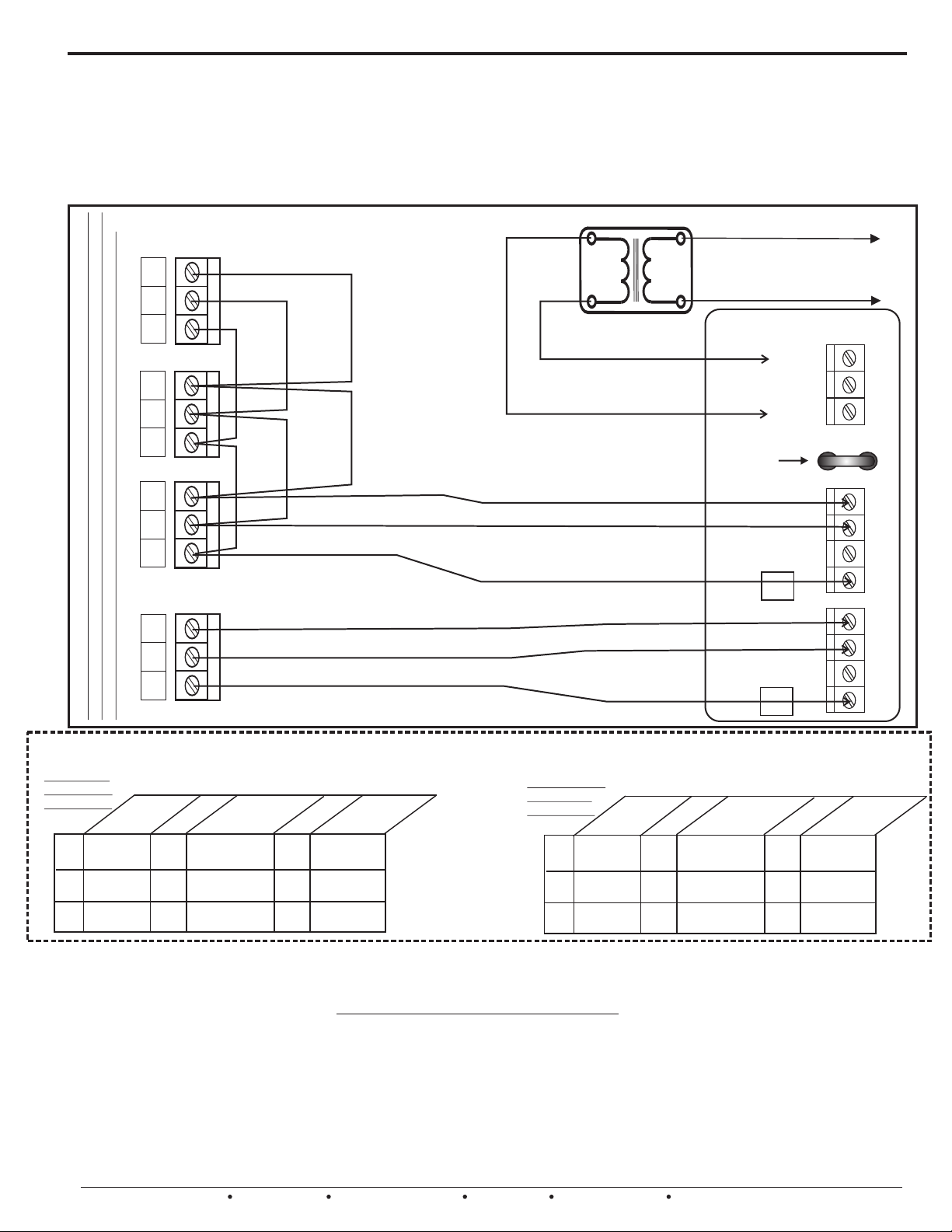
DAMPER WIRING, DAMPER TESTING AND POWER SUPPLY SOLUTIONS
Unlike previous models, the UZC4 series allows “Damper Motor Power Isolation” on the Main and Expansion
modules. The Main Module’s motor blocks can be isolated only if necessary, but the Expansion module motor blocks
must be powered by a separate transformer. This advanced design provides automatic 2.5amp over-current
protection for each Expansion module motor block and allows a maximum 60va transformer to be connected. This
means that you can directly connect a theoretical maximum of 12 Genuine ND/URD dampers to a single 2 zone
expansion module. Now you no longer have to isolate & power up multiple dampers using field installed relays. The
Expansion modules provide the isolation for you. See the diagram below for typical wiring solutions for dampers.
Typical damper power wiring for a ZXM2 Expansion Module.
A single damper on the first expansion zone
and three dampers on the next. Your
actual number of dampers per zone may vary.
C
6
4
1
H
Separate 24 vac
Transformer
60va MAX
L2
To Line Voltage
Provide over current
protection
L1
ZXM2 MODULE
MXR
6
4
1
THERMAL
CIRCUIT
BREAKER
6
4
1
MXC
D
M
P
R
F1
M6
M4
M2
M1
D
6
4
1
Figure 36.
Genuine ND and URD dampers wired in series or parallel configuration. NOTE: Some
older style dampers and competitor’s dampers cannot be paralleled and must be
isolated or wired in tandem. Contact EWC Controls Technical Support for assistance.
M
P
R
M6
M4
M2
M1
UZC4 Recommended Power Solutions
ND / URD’s
@ 3.5 - 5 va
per damper
4
40va
6
40va
8
50va
Number of Zones
Non-inherently current limiting transformers must have field provided over-current protection on the secondary 24 vac output. The table values
provided pertain to genuine ULTRAZONE Dampers and Competitors typical 24 vac Spring loaded dampers. Included in these VA load ratings are the
correct number of thermostats, the UZC4 Zone System, and a 5% field factor. Spring loaded dampers draw higher currents & require more power.
Number of Dampers Directly Connected to Main Module
1
-
4
10
12
14
ones
Z
1-
50va
60va
60va
4
16
18
20
ones
Z
75va
75va
75va
1-
4
Use class 2 UL
Listed 1585
inherently
current limiting
transformers
only!
TE S T I NG D AM P E R MOTORS
ND / URD / SMD / BMD Dampers - Connect 24vac common to terminal 1 and 24vac hot to terminal 4. Damper should
Open. Remove 24vac hot from terminal 4 and apply to terminal 6. Damper should Close
RDN / SMDL / BMDL Dampers - Connect 24vac common to terminal 1 and 24vac hot to terminals 2 and 4. Damper
should Open. Remove 24vac hot from terminal 4. Damper should Close.
SR / ESR Power Close / Spring Open Dampers - Connect 24vac common & hot to the two motor (M) terminals.
Damper should Close. Remove 24 vac hot. Damper should Open.
SR / ESR Power Open / Spring Close Dampers - Connect 24vac common & hot to the two motor (M) terminals.
Damper should Open. Remove 24vac hot. Damper should Close.
20
EWC Controls Inc. 385 Highway 33 Englishtown, NJ 07726 800-446-3110 FAX 732-446-5362 E-Mail- [email protected]
Spring Types
@ 8 - 10 va
per damper
4
40va
6
50va
8
50va
Number of Zones
Number of Dampers Directly Connected to Main Module
Zone
s
1-
60va
60va
75va
4
16
18
20
ones
Z
75va
100va
100va
1- 4
1-
4
10
12
14
Page 21
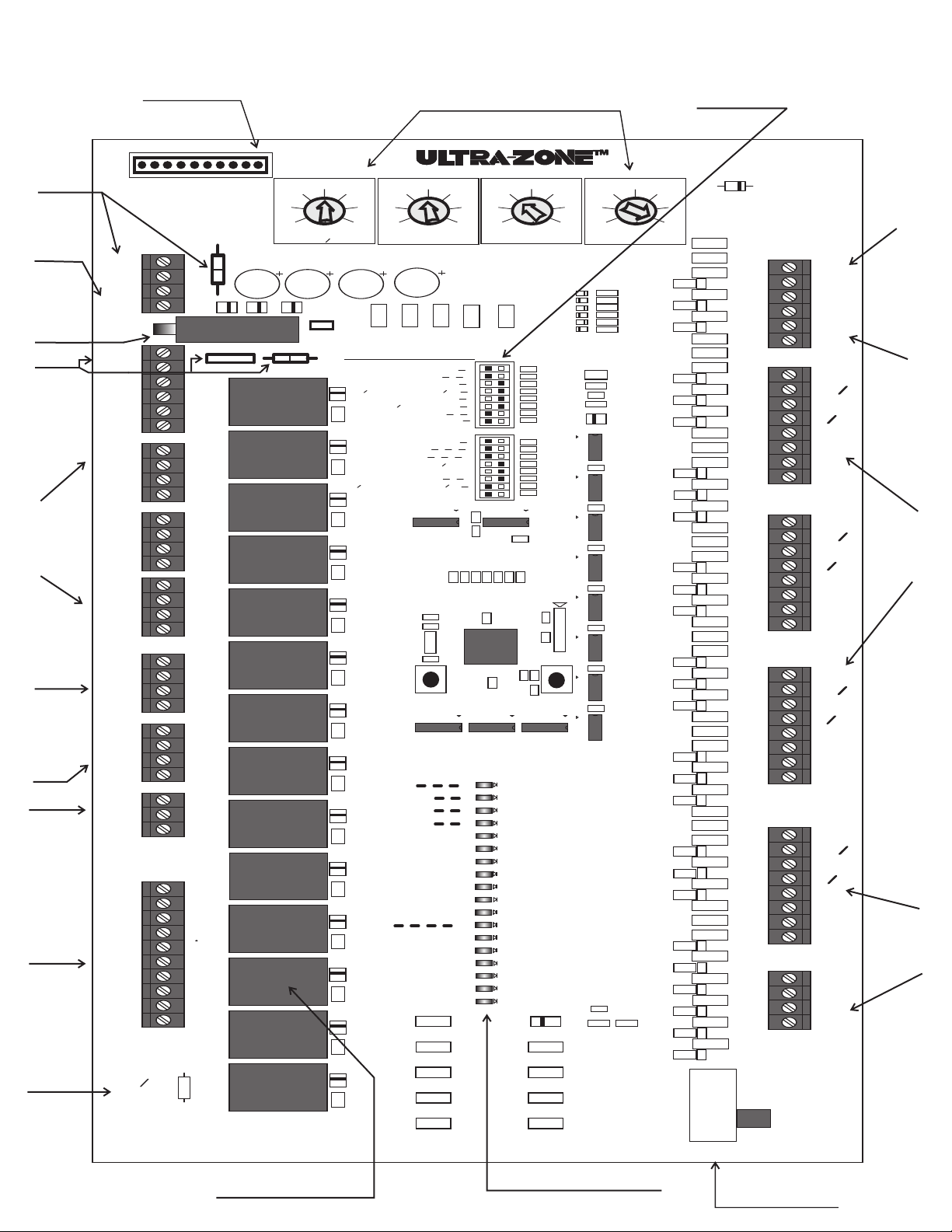
UZC4 FEATURES AT A GLANCE
Fire Alarm
Interlock
Terminals
and
Cuttable
Link
Polarized
Power
Input
Terminals
Resettable
Circuit
Breaker with
LED fault
indicator
4.0 amp
ISOLATING
DAMPER
POWER
TERMINAL
BLOCK,
BREAKER &
CUTTABLE
LINK
Rugged
Damper
Motor
Terminal
Blocks
Outside
Air
Damper
Terminal
Block
Electronic
Bypass
Damper
Terminal
Block
Multi
Function
Auxilary
Terminal
Block
Isolated
HVAC
System
Terminal
Block
On-Board
System
Rc/Rh Link
FA
FA
24V
24V
RESET
MXR
MXC
M6
M4
M2
M1
M6
M4
M2
M1
M6
M4
M2
M1
M6
M4
M2
M1
M6
M4
M2
M1
M6
M4
M2
M1
NC
NO
C
G
Y2
Y1
O
B
W1
W2
E
RC
RH
RC
LINK
W
E
Rugged 10 pin
Expansion Header
Protective
header cap not
shown for clarity
J1
HVAC ZONE
CONTROL
SYSTEM
JMP1
TB1
R
C
TB2
TB3
CB1
F1
K1
Z
O
4
N
E
K2
Z
O
3
N
E
TB4
K3 K4
Z
O
2
N
E
TB5
K5
Z
O
1
N
E
TB6
O
A
D
M
P
R
TB7
K7
E
B
K8
D
TB8
A
U
X
K9
R
L
Y
K10 K11
TB9
H
V
A
C
S
K12 K13
Y
S
T
E
M
JMP3
RH
K14
CONTROLS INC.
Englishtown, NJ
C
33
40
47
R65
R66
R68
R70
R72
R73
R74
R76
R78
R80
R81
R82
R84
R86
R88
R89
R90
R92
R94
R96
R97
R98
R100
R102
R104
R105
R106
R108
R110
R112
R113
R114
R116
R118
R120
R121
R122
R124
R126
R128
R130
R132
SW3
Easy Setup
16 Switch Bank
UZC4
14
D
R64
S
E
C25
N
S
C26
O
C27
R
S
TB11
C28
T
C29
S
T
C30
A
T
4
C31
C32
TB12
C33
T
S
C34
T
A
C35
T
C36
3
C37
TB13
C38
T
C39
S
T
A
T
C40
2
C41
C42
TB14
C43
T
S
C44
T
C45
A
T
1
C46
C47
C48
C49
C50
C51
EMERGENCY
TB10
TB15
SAS
SAS
OAS
OAS
RAS
RAS
C
W1
W2
O
Y1
Y2
R
G
17
18
C
W1
W2
O
Y1
Y2
R
G
C
W1
W2
O
Y1
Y2
R
G
C
W1
W2
O
Y1
Y2
R
G
ONE
ZONE
AUX R
CO
CO
E
B
E
B
E
B
E
B
2
2
Supply,
Outside,
& Return
Air Sensor
Terminal
Blocks
Rugged &
Versatile
Thermostat
Terminal
Blocks
Multi
Functional
Zone 1
Thermostat
Terminal
Block
User Friendly Adjustable
Multi-function Potentiometers
21
14
7
OFF
TIMER
C1
D1
C2
D2
28
STAGING
OAS
R1
C54
D24
LED19
GROUND FAULT
35
42
R52
43
40
37
34
R19
COOLING
LIMIT
R2
C53
R20
46
49
52
R21
SWITCH LEGEND
JMP2
HP
SYSTEM
>
HP
DF
< >
D3
OFF
<
90
s
<
OAS
<
OFF
<
OFF
<
GAS
<
HC
1
CS#
<
RV
O
<
OFF
RA
<
OFF
<
0
RA LMT
<
ANY
<
STATUS
OAS
SAS
R10
D9
R11
D10
R12
D11
R5
D4
R6
D5
R7
D6
R8
D7
R9
D8
RAS
ZONE
R13
ZONE
D12
ZONE
ZONE
OA DMPR
R14
BYPASS
D13
AUX RELAY
FAN
COMPRESSOR2
R15
COMPRESSOR1
D14
REV
W1 HEAT
W2 HEAT
EMERGENCY
R16
D15
R17
D16
R18
>
CONV
FAN PRG
PURGE
>
STAGES
R
%
50
>
ON
SAS
>
HYDRO
FAN
>
TSTAT
>
>
2
>
B
>
ZDL
>
<
AUX RLY
RAS
ON
>
>
FAN CTRL
R48
C17
Y1
R50
SW1
TIMER
RESET
LIMIT
LIMIT
LIMIT
4
OPEN
3
OPEN
2
OPEN
1
OPEN
DMPR
VALVE ‘O’
GAS
ON
>
180
TMR
>
ON
HP
ON
DA
>
+10
>
U14
U19
OPEN
R52
R53
R54
R55
R63
s
Z
1
C8
R47
C10C9C11
U1
C21
120
110
C18
130
U15
C12
U18
HEATING
R22
C13
R58
LED1
LED2
LED3
LED4
LED5
LED6
LED7
LED8
LED9
LED10
LED11
LED12
LED13
LED14
LED15
LED16
LED17
LED18
140
1ST
BANK1
BANK2
C14
R51
STAGE
R3
C7
C15
150
160
170
LIMIT
D17
D18
D19
D20
D21
D22
R29
R30
R31
R32
R33
R34
R35
D23
R36
R37
R38
R39
R40
R41
R42
R43
R44
J2
R49
C19
SW2
C22
CPU
RESET
U17
Z1
R56
R57
R60
R61
R50
R45
R46
C3
12
MULTI
C52
R134
19
5
26
STAGE
DIFFERENTIAL
R4
R67
R23
R24
R69
R25
R26
R27
R71
R28
R75
R77
R79
U2
C4
R83
U3
R85
C5
U4
R87
C6
U5
R91
C16
R93
U6
R95
C20
U7
R99
C23
U8
R101
R103
C24
U9
R107
R109
R111
R115
R117
R119
R123
R125
R127
R129
R135
R130
R133
HEAT
NORMAL
Figure 37.
Heavy duty 10 amp
contact rated relays
Bright System Status LED’s
On-Board
Emergency Switch
21
Page 22
UZC4 LED FUNCTION AND DESCRIPTION
GREEN
RED
RED
RED
GREEN
GREEN
GREEN
GREEN
GREEN
GREEN
ORANGE
UZC4
LED’s
POWER
OAS
SAS
RAS
The SAS LIMIT LED illuminates solid to indicate that the Supply Temperature has exceeded the chosen
set point on either the HIGH TEMP LIMIT or the LOW TEMP LIMIT. LED will blink rapidly
to indicate a malfunctioning Supply Air Sensor.
The RAS LIMIT LED illuminates solid to indicate that the Return Temperature has exceeded the chosen
set point. LED will blink rapidly to indicate a malfunctioning Return Air Sensor.
ZONE 4 OPEN
ZONE 3 OPEN
ZONE 2 OPEN
ZONE 1 OPEN
OA DMPR OPEN
BYPASS DMPR
AUX RELAY
The UZC4 is equipped with 18 LED’s which indicate system operation and status. Familiarize
yourself with the LED’s definitions, in order to quickly determine the system status and mode of
operation.
The POWER LED pulses as a steady heart beat to indicate proper Microprocessor operation.
The OAS LIMIT LED illuminates solid to indicate that the Outdoor Temperature has fallen below the chosen
set point. LED will blink rapidly to indicate a malfunctioning Outdoor Air Sensor.
ZONE 4 LED will illuminate solid to indicate that damper(s) is energized open, and the Zone is active.
ZONE 3 LED will illuminate solid to indicate that damper(s) is energized open, and the Zone is active.
ZONE 2 LED will illuminate solid to indicate that damper(s) is energized open, and the Zone is active.
ZONE 1 LED will illuminate solid to indicate that damper(s) is energized open, and the Zone is active.
The OA DMPR OPEN LED will illuminate solid to indicate that the Outside Air damper is energized
open in response to the CO2 detector or other device to provide demand based ventilation.
The BYPASS DMPR LED will illuminate solid to indicate that the Bypass damper(s) is
being forced to the Open position. Occurs during idle, short cycle and changeover periods.
The AUX RELAY LED will illuminate solid to indicate that the Auxilary relay is being
energized in response to a demand, to start a function such as Humidify or De-humidify.
GREEN
YELLOW
YELLOW
ORANGE
RED
RED
RED
RED
FAN
The FAN LED will illuminate solid to indicate a demand for fan operation, during COOLING, HEATING,
PURGE, or CONTINUOUS FAN operations.
COMPRESSOR 2
COMPRESSOR 1
REV VALVE ’O’
W1 HEAT
W2 HEAT
EMERGENCY
GROUND FAULT
The REV VALVE ‘O’ LED will illuminate solid to indicate that the reversing valve on a heat pump
system is being energized to the COOL position. The LED will be out during heating mode on a
heat pump.
The W1 LED illuminates solid to indicate 1st stage of HEATING is energized in a conventional
HVAC system. Or the W1 LED illuminates solid to indicate the 1st stage of Auxiliary or Backup heat
is energized in a heat pump system. (3rd stage heat) Also illuminates during Emergency mode.
The W2 LED illuminates solid to indicate 2nd stage of HEATING is energized in a conventional
HVAC system. Or the W2 LED illuminates solid to indicate the 2nd stage of Auxiliary or Backup heat
is energized in a heat pump system. (4th stage heat) Also illuminates during Emergency mode.
The EMERGENCY LED illuminates solid to indicate all stages of Auxiliary, Backup, and Standby Heat
have been energized and Compressor 1 and 2 have been locked out. This is done in response to a
demand from any Heat Pump thermostat connected to any zone. It can also be activated via the
On-board Emergency switch. When Emergency mode is activated, the W1 & W2 LED’s will also
illuminate.
The GROUND FAULT LED illuminates when the Circuit Breaker Trips due to an electrical short in
the thermostat field wiring or possibly in the main module damper field wiring. The electrical short
must be located and repaired before the circuit breaker can be reset to normal.
The COMPRESSOR 2 LED illuminates solid to indicate the 2nd stage compressor is energized.
The COMPRESSOR 1 LED illuminates solid to indicate the 1st stage compressor is energized.
22
EWC Controls Inc. 385 Highway 33 Englishtown, NJ 07726 800-446-3110 FAX 732-446-5362 E-Mail- [email protected]
Page 23
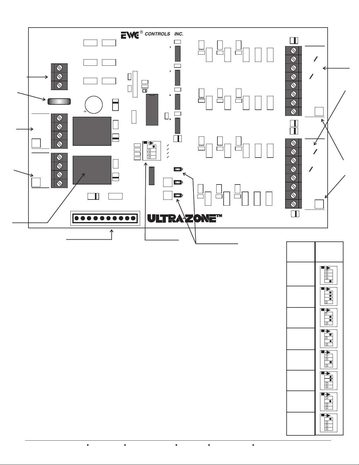
ZXM2 FEATURES AT A GLANCE
POLARIZED
ISOLATING
DAMPER
POWER
TERMINAL
BLOCK &
2.5 amp
BREAKER
Rugged
Damper
Motor
Terminal
Blocks
with
ZONE ID
blocks
Heavy
duty
10 amp
contact
rated
relays
ZXM2
MXR
MXC
D
M6
M
M4
P
M2
R
6
D
M6
M
M4
P
R
M2
5
M1
TB1
TB2
TB3
R1
R3
R5
F1
K1
R2
R4
J1
Z1
R9
R10
R7
C3
R8
U1
SW1
CTS 206-4
D4
C8
O
N
12 34
0
A
1
>
>
0
A
2
>
>
0
A
4
>
>
8
0
A
>
>
LED1
C2
Y1
D2
R12
R13
R14
R15
R6
C1
R16
C4
U2
C9
C5
U3
R24
C6
U4
C12
C7
U5
R32
D5
C15
R17
R25
R33
R18
C10
R26
C13
R34
C16
R19
R27
R35
R20
C11
R28
C14
R36
C17
R21
R29
R37
R22
R30
R38
R23
R31
TB5
R39
STATUS
D3
K2
D1
R11
U6
6
DMPR
5
J2
LED2
LED3
R40
C18
R41
R42
C19
R43
R44
C20
R45
R46
R47
TB4
D6
C
E
W1
W2
O
Y1
Y2
R
G
D7
D8
B
6
T
S
T
A
T
Rugged &
Versatile
Thermostat
Terminal
Blocks
C
E
W1
W2
O
Y1
Y2
R
G
D9
B
5
T
S
T
A
T
FIELD
ZONE ID
Blocks
Rugged 10 pin
Expansion Header
Bus Cable not shown for clarity
4 Switch ZONE
ADDRESS Bank
Bright STATUS LED
and DAMPER LED’S
with ZONE ID blocks
The ZXM2 Expansion Module for the UZC4 series is pictured above. A
total of eight (8) ZXM2’s can be connected to the UZC4 to create a 20 ZONE
system! The modules are housed and linked together via a factory supplied
10 conductor BUS CABLE and a unique Expansion Header Card. The
UZC4 expands by connecting factory assembled Expansion Systems
such as the ZXM2A, ZXM4A and ZXM6A that are pre-wired and
configured for you at the factory. The UZC4 connects to these housed
expansion assemblies via a flexible 20” long bus cable. Each Expansion
module has a set of address switches that must be set properly to allow the
UZC4 to recognize each expansion module in the correct order. Note the
“STATUS” LED provided on every Expansion Module to indicate
active micro-processor operation. There are also two “DAMPER”
LED’s provided to indicate which damper(s) are energized open or
closed. Next to each Damper and Thermostat terminal block is a blank
white square, where the “Zone Number” can be written to easily identify it as
a new expanded zone. These blocks will be filled in for you at the factory
when a UZC 6 zone, 8 zone, 10 zone or higher has been ordered. The ZXM2
address switches will also be factory set for you. Note the same multi-input
thermostat terminals are supplied on the ZXM2 as are supplied on the
UZC4 Main Module. Most Important of all is to note the MXR & MXC
Damper Motor Power Input Block. The ZXM2 Expansion Module is
powered via the Bus Cable from the UZC4, but the power for the
dampers must be provided by a separate transformer and is isolated
from the module. This allows great freedom to connect as many dampers
as the 2.5 amp thermal breaker can handle. See page 19 for damper motor
power supply details. Make sure to read the ZXM2 Technical Bulletin for
the proper cabling scenarios and zone address settings for your
system or refer to the chart on the right.
All Expansion module
Dip switch banks must
be set correctly for
proper zone address
identification. The 1st
expansion module
would be zones 5 & 6.
The 2nd expansion
module would be zones
7 & 8. The 3rd
expansion module
would be zones 9 & 10.
And so on up the line
for a total of 20 zones.
The switches are set
for you at the factory
unless you are
expanding the system
in the field. It is a good
idea to check them
anyway.
Expansion
Panel No.
8
7
6
5
4
3
2
1
Dip
Switch
Settings
N
CTS 206-4
N
CTS 206-4
N
CTS 206-4
N
CTS 206-4
N
CTS 206-4
N
CTS 206-4
N
CTS 206-4
N
CTS 206-4
O
12 3 4
O
12 3 4
O
12 3 4
O
12 3 4
O
12 3 4
O
12 3 4
O
12 3 4
O
12 3 4
EWC Controls Inc. 385 Highway 33 Englishtown, NJ 07726 800-446-3110 FAX 732-446-5362 E-Mail- [email protected]
23
Page 24
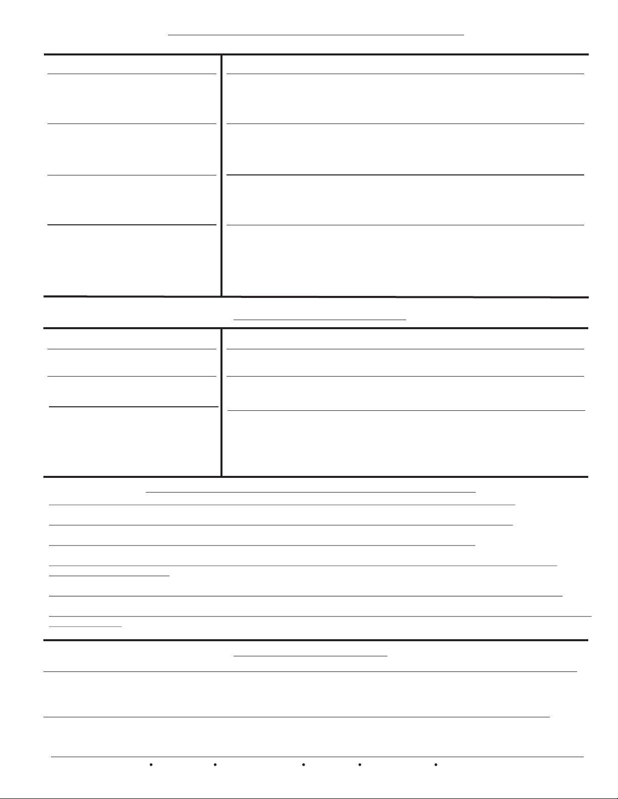
T R O U B L E S H O O T I N G
SYMPTOM
LED’S are responding properly but
HVAC system is malfunctioning.
LED’s are not responding properly
and HVAC system is malfunctioning.
LED’s illuminate and HVAC system
functions normally but dampers do
not respond.
LED’s do not illuminate and HVAC
system does not respond.
DETECTING 24vac SHORTS
HVAC system not responding and
UZC4 LED’s are Off.
Dampers not responding and THE
UZC4 LED’s are Off or On.
ISOLATING 24vac SHORTS
F1 circuit breaker protects the UZC4
and all connected modules. Reacts to
a short in the damper motor or
thermostat component and field wiring.
SOLUTIONS
Check HVAC system wiring for proper connections.
Check HVAC system wiring for shorts/miswiring.
Check HVAC System.
Check HVAC System technical documentation and Mfr’s Technical Support.
Check HVAC system wiring for shorts/miswiring.
Check HVAC system wiring for proper connections.
Check HVAC thermostat for proper connections.
Refer to Technical Bulletin for correct Setup/Wiring/Dip Switch settings.
Check damper motor wiring for proper connections.
Check damper motor 24vac transformer voltage/fuse/UZC4 circuit breaker.
Check damper motor wiring for shorts/miswiring.
Refer to Technical Bulletin for correct Setup/Wiring.
REFER TO THE DAMPER MOTOR TESTING PAGE 8
Check HVAC/UZC4 system transformer supply voltage.
Check HVAC/UZC4 system 24vac transformer voltage/fuse/UZC4 circuit
breaker. Check the Fire Alarm system. The UZC4 will not operate if the fire
alarm is active and the interlock is used. 24vac can be read across an open FA circuit.
CHECK YOUR WIRING
SYMPTOMS: Modules, Motors or both will not function
If 24vac short has occurred, 24vac will be present at the UZC4 Module Input terminals R & C; but
24vac will not be present at the Thermostat R&C terminals. The Ground Fault LED is illuminated!
SOLUTIONS: Remove 24vac power from UZC4 and reset the manual circuit breaker or allow
the thermal breaker to cool off. Find and repair short(s) in damper and/or thermostat field wiring.
Restore 24 vac power.
Disconnect the wire(s) from the ‘R’ terminals on the UZC4 thermostat terminal
blocks , and the “M2/M4/M6’’ terminals on the UZC4 damper motor terminal
blocks. Restore power. If the short is no longer present, Ohm out the
thermostat and damper field wiring for shorts/misconnections. Replace or repair
wires as necessary. Restore power. Module(s) will resume operation.
TE STI NG C ONV EN TIO NA L TH ERM OS TATS
During a demand for heating, the thermostat should apply a 24vac hot signal to the W1 and or W2 terminals.
During a demand for cooling, the thermostat should apply a 24vac hot signal to the Y1, Y2 and G terminals.
During a continuous fan demand, the thermostat should apply a 24vac hot signal to the G terminal.
Check to make sure that the thermostat Rc and Rh terminals are connected together, unless your application requires
separation of these circuits.
Use the (C) Common terminal provided at each thermostat terminal block to wire up full 24 vac hard-wired thermostats.
You should reference the (C) Common terminal when troubleshooting incoming thermostat demand signals, even if no wire is
connected there.
TECHNICAL SUPPORT
EWC Controls provides superior toll free Troubleshooting Support for the UZC4 when you are on the job site!
Call 1-800-446-3110 Monday - Friday 8am to 5pm East Coast Time.
Otherwise call 1-732-446-3110 for information on the UZC4 and other ULTRA-ZONE products.
When calling for Technical Support, please have a multi-meter, pocket screwdriver, and wire cutter/stripper handy.
24
EWC Controls Inc. 385 Highway 33 Englishtown, NJ 07726 800-446-3110 FAX 732-446-5362 E-Mail- [email protected]
 Loading...