

EWC Controls Ultra-Zone UZC4 Technical Bulletin
®
Forced Air Zone Controls
Model UZC4 Zone Control
The UZC4 Universal Zone Control System allows you to easily
upgrade an inefficient single zone HVAC system, into an
Automated, Multi-zone, Energy saving, Comfort producing,
Safety Minded, HVAC system. With Superior design, Intuitive
firmware, Building Code Compliant support, Simple setup
options, and Easy to understand wiring, the UZC4 Zoning
system is the Designer/Contractors dream. Combined with
Patented EWC motorized dampers and practically any Off-theshelf Conventional or Heat Pump style Thermostats,
EWC has set a New Industry Standard in Large
Residential and Commercial HVAC Air Zoning Systems.
Zone
Capacity
The main module controls four air zones
using 24 vac motorized air dampers and
may be expanded up to 22 zones, using
ZXM2 Expansion Modules. See page 23.
Compatible
HVAC
Systems
The UZC4 will Control 2, 3 & 4 stage
Conventional, GeoThermal or Dual Fuel
Heat pumps, without the need for dual
fuel kits. Also single or multi-stage Gas,
Oil, & Hydronic HVAC systems, with
single or two stage cooling and Constant
or Variable speed fan systems.
Compatible
Thermostats
Automatic
Heat/Cool
Changeover
Status LED
Compatible with most Off the shelf 1 or 2
stage Conventional Heat/Cool or Heat
Pump Thermostats. All Mechanical,
Digital/Electronic, Dual Mode, and Internet
Compatible Thermostats that operate on
24vac. Battery powered or Power robbing
thermostats that draw less than 20 ma of
current are also compatible. Zone 1 will
accept One Zone Mode, Carbon Dioxide
Safety and Auxiliary/Dehumidify mode
inputs. See pages 9-11 & 14-17 for details.
The UZC4 Zone system features
automatic changeover from any
thermostat allowing for individual zone
comfort from the HVAC system.
The STATUS LED pulses as a steady
heart beat to indicate active Microprocessor status.
System LEDs
On board Multi-colored LED’s will
illuminate to indicate system status,
HVAC system mode, and active / inactive
zone identification. See page 22 for details.
Damper LEDs
Damper 1 thru Damper 22 green LEDs
will indicate which zone dampers are
demanded to energize Open or Closed.
Operating
Power
TB-221
EWC Controls Inc. 385 Highway 33 Englishtown, NJ 07726 800-446-3110 FAX 732-446-5362 E-Mail- info@ewccontrols.com
P/N 090375A0221 Revision S 09.04.12
INPUT VOLTAGE: 19-30VAC 60 Hz
Transformer 40-100VA MAX. NEC Class
2.
CURRENT DRAW: Max 22VA @ 24VAC.
OVER-CURRENT PROTECTION: 4.0
amp or 100VA.
Copyright © 2004 EWC Controls Inc., All Rights Reserved
HVAC ZONE
CONTROl SYSTEM
FA
FA
24V
24V
RESET
MXR
MXC
M6
M4
M2
M1
M6
M4
M2
M1
M6
M4
M2
M1
M6
M4
M2
M1
M6
M4
M2
M1
M6
M4
M2
M1
NC
NO
C
G
Y2
Y1
O
B
W1
W2
E
RC
RH
RH
RC
LINK
W
E
Box Contents
Manual
and
Automatic
Thermal
Circuit
Breakers
Operating
Conditions
Indoor Fan
Control
Leave this bulletin on the job site for future reference!
J1
TB1
TB2
TB3
TB4
TB5
TB6
TB7
TB8
TB9
JMP3
C
JMP1
C1
R
C
D1
CB1
F1
K1
Z
O
4
N
E
K2
Z
O
3
N
E
K3 K4
Z
O
2
N
E
K5
Z
O
1
N
E
O
A
D
M
P
R
K7
E
B
D
K8
A
U
X
K9
R
L
Y
K10 K11
H
V
A
C
S
K12 K13
Y
S
T
E
M
K14
CONTROLS INC.
Englishtown, NJ
D2
JMP2
14
7
OFF
STAGING
TIMER
C2
LED19
GROUND FAULT
R1
21
28
40
35
37
42
34
OAS
C54
R20
R19
HP
SYSTEM
>
HP
DF
< >
D3
OFF
FAN PRG
<
PURGE
90
s
<
STAGES
OAS
<
OFF
50
<
OFF
SAS
<
FAN
GAS
<
R5
D4
TSTAT
HC
>
1
CS#
<
RV
O
<
OFF
<
RA
AUX RLY
<
R6
RAS
OFF
<
D5
0
RA LMT
<
FAN CTRL
ANY
<
R7
D6
R8
D7
R9
D8
R10
D9
R11
D10
STATUS
R12
OAS
D11
SAS
RAS
ZONE
R13
ZONE
D12
ZONE
ZONE
DMPR
R14
BYPASS
D13
AUX RELAY
FAN
COMPRESSOR2
R15
COMPRESSOR1
D14
REV
W1 HEAT
W2 HEAT
EMERGENCY
R16
D15
R17
D16
R18
C53
CONV
%
>
>
ZDL
R48
C17
Y1
R50
SW1
LIMIT
LIMIT
LIMIT
4
3
2
1
VALVE
COOLING
LIMIT
R2
>
>
R
>
>
>
>
2
B
>
>
>
TIMER
RESET
OPEN
OPEN
OPEN
OPEN
43
GAS
>
180
TMR
>
ON
ON
HYDRO
HP
ON
>
ON
+10
U14
U19
OPENOA
DMPR
R52
R53
R54
R55
R63
140
130
46
120
49
110
52
1ST
STAGE
HEATING
LIMIT
R3
R21
R22
BANK1
R29
R30
ON
s
DA
Z
1
>
U1
R31
R32
R33
R34
R35
R36
BANK2
R37
R38
R39
R40
R41
R42
R43
R44
C8
C7
U15
R47
C10C9C11
C12
C13
C14
C15
C18
R49
C19
C22
R58
C21
R51
CPU
RESET
U17
U18
LED1
LED2
LED3
LED4
LED5
LED6
LED7
LED8
LED9
LED10
LED11
LED12
LED13
LED14
LED15
LED16
LED17
LED18
Z1
R56
R57
R60
R61
26
150
19
160
12
170
5
STAGE
MULTI
DIFFERENTIAL
R4
R23
D17
R24
D18
R25
D19
D20
R26
D21
R27
R28
D22
R50
R45
C3
R46
D23
U2
C4
U3
C5
U4
C6
U5
C16
J2
U6
C20
U7
SW2
C23
U8
C24
U9
C52
R135
R134
UZC4
33
40
47
R64
HEAT
R65
S
R66
E
C25
R67
R69
R71
R75
R77
R79
R83
R85
R87
R91
R93
R95
R99
R101
R103
R107
R109
R111
R112
R115
R117
R119
R120
R123
R125
R126
R127
R128
R129
R130
R133
SW3
R68
R70
R72
R73
R74
R76
R78
R80
R81
R82
R84
R86
R88
R89
R90
R92
R94
R96
R97
R98
R100
R102
R104
R105
R106
R108
R110
R113
R114
R116
R118
R121
R122
R124
R130
R132
N
S
C26
O
C27
R
S
TB11
C28
T
C29
S
T
C30
A
T
4
C31
C32
TB12
C33
T
S
T
C34
A
C35
T
3
C36
C37
TB13
C38
T
C39
S
T
A
T
C40
2
C41
C42
TB14
C43
T
S
C44
T
A
C45
T
1
C46
C47
C48
C49
C50
C51
EMERGENCY
NORMAL
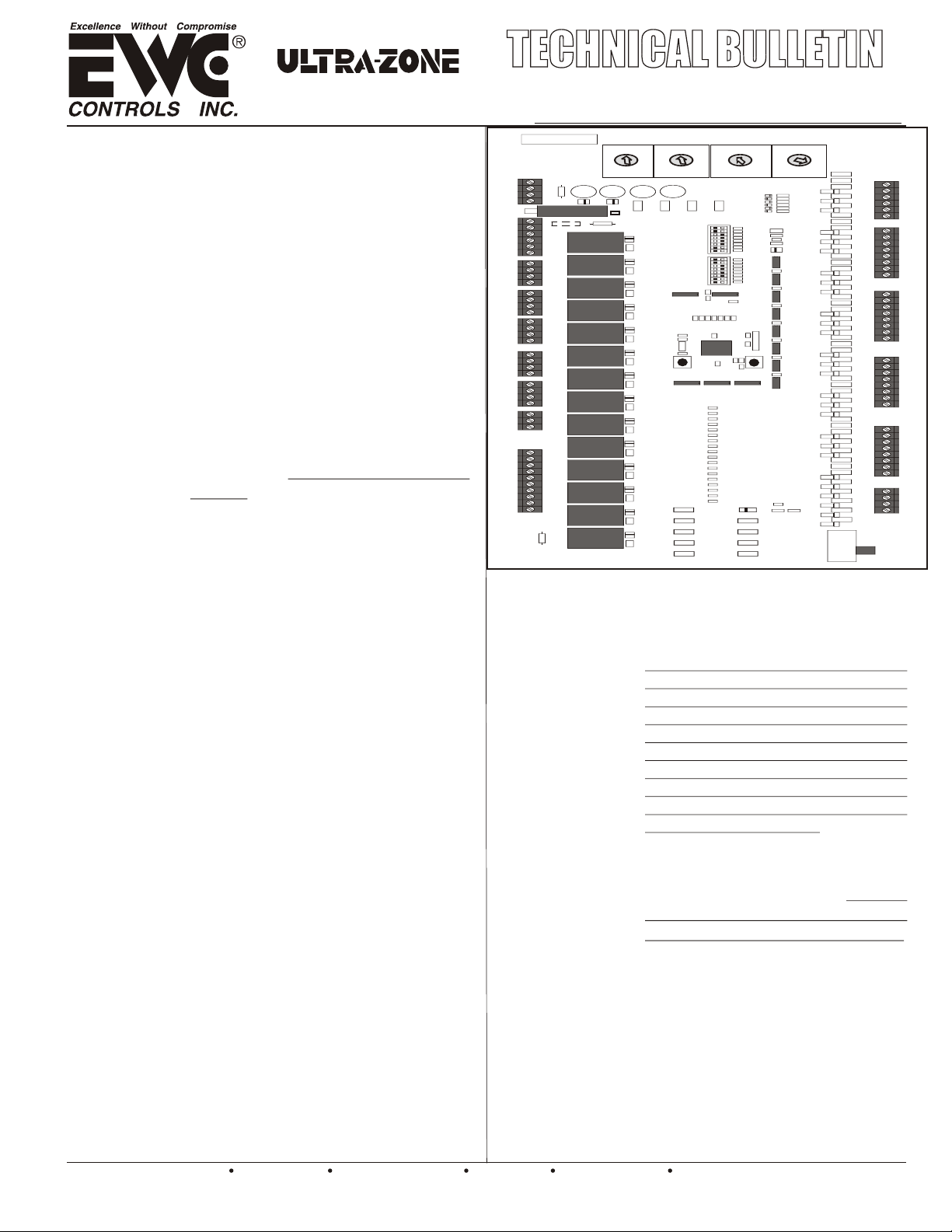
* UZC4 Zone Control Panel
* Supply Air Sensor
* Technical Bulletin TB221
* Mounting Hardware
The main UZC4 module has a Manual
Reset circuit breaker with a Ground
Fault Indicator that protects all
connected modules and thermostat
circuitry. All modules have separate
damper motor Thermal Breakers too.
They protect the damper motor circuitry
from shorts in the field wiring. The
breakers will not protect against shorts
in the HVAC system wiring.
CAUTION: When the thermal
breaker is tripped it will get quite
hot. To reset the breaker: Shut off
power to the panel. Find and repair
the short. Restore the 24VAC power.
TEMPERATURE: -20° to 160°F (-29° to 71°C)
HUMIDITY: 0% - 95% RH Non-Condensing.
The UZC4 allows constant operation of
the Indoor Fan by Thermostat #1 only, or
by each individual thermostat. When
controlled by thermostat #1, All Zone
dampers will respond. When controlled
individually, Zones not calling for
continuous fan will close.
TB10
TB15
Figure 1.
SAS
SAS
OAS
OAS
RAS
RAS
C
W1
W2
O
Y1
Y2
R
G
C
W1
W2
O
Y1
Y2
R
G
C
W1
W2
O
Y1
Y2
R
G
C
W1
W2
O
Y1
Y2
R
G
ONE
ZONE
AUX R
CO
CO
1
E
B
E
B
E
B
E
B
2
2
UZC4 STANDARD FIRMWARE AND HARDWARE FEATURESUZC4 STANDARD FIRMWARE AND HARDWARE FEATURES
Indoor Fan
Control
During
Heating
Built-In
Timer
Settings
Definitions
are explained
below
*Short Cycle
Timer
*Changeover
Timer
*Inter-stage
Timer
*Opposite
Mode
Delay Timer
*Staging
Timer / OAS
21
14
7
OFF
MULTISTAGE
Timer / OAS
28
35
42
OFF or
7 to 42
minutes or
7 to 42
degrees F.
Use when Timer
or Outside Air
Changeover is
required.
See Page 7
*Supply/Return
Air Limit
Delay Timer
2
EWC Controls Inc. 385 Highway 33 Englishtown, NJ 07726 800-446-3110 FAX 732-446-5362 E-Mail- info@ewccontrols.com
A dip switch is provided to enable automatic fan
operation in heat mode. Useful for straight
electric heat or hydronic heat applications.
NOTE: Fan mode is automatically set when
Heat Pump is selected.
The panel has built-in delay timers that
insure safe & reliable operation.
*Short Cycle Timer
*Changeover Timer
*Inter-stage Timer
*Opposite Mode
3 minutes - Fixed.
4 minutes - Fixed.
2 minutes - Fixed.
20 minutes - Fixed.
Delay Timer
*Staging Timer
OAS Setting
*Supply / Return
7 to 42 minutes
or 7 to 42 F°
3 minutes - Fixed.
Air Limit Delay Timer
When all zone demands are satisfied, the
panel will not resume the same mode
operation for a minimum of 3 minutes.
When a demand to Change Over has
been honored. A 4 minute delay timer
prevents the system from rapidly
changing between Heat to Cool, or Cool
to Heat mode.
2 minute time delay that occurs between
thermostatic demands to stage up or down.
A 20 minute delay must expire, or all
active zone(s) must satisfy, before
the UZC4 will honor a thermostat
demand to changeover to the
opposite mode of system operation. The
delay is fixed & cannot be changed or defeated.
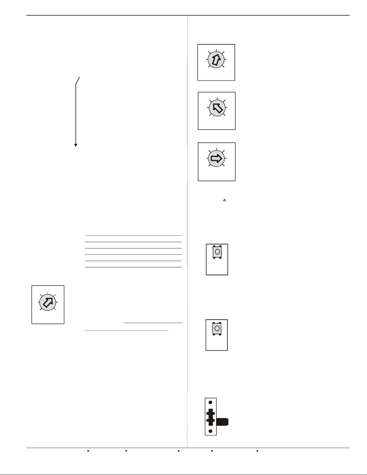
The STAGING TIMER sets the
amount of continuous & cumulative
call time in 1st stage, before second
stage heat or cool is energized. Also
applies to 3rd & 4th stage heat.
NOTE: The potentiometer also
serves as the 2nd or 3rd stage Heat,
Outside Air Changeover Setting.
The UZC4 can inhibit 2nd or 3rd stage
heat based on Time or Outside Air
Temperature. All staging scenarios
depend upon the type of thermostat
used. See page 5 & 7 for details.
NOTE: An Optional OAS Sensor is required to
use the OAS feature. NOTE: Y2 Output
defaults to 30 minutes, if OAS is chosen and
single stage thermostats are used.
The time delay of 3 minutes must
expire before the UZC4 will reenergize heat or cool mode. This
occurs when the processor detects
the supply or return air temperature is
higher or lower than the Heat/Cool
limit settings.
Cooling and Heating Limit Controls
The operational sequence of the limit controls depends upon the
dip switch settings chosen on the UZC4 main module. Multistage
Heat Pump sequence will differ from Conventional Gas/Electric.
43
40
37
34
COOLING LIMIT
130
120
110
1st STAGE
HEAT LIMIT
19
12
5
MULTI STAGE HEAT
DIFFERENTIAL
Example:
Example:
Hi Temp. limit=130
Hi Temp. limit=130
Plus M. stg T= 40
Plus M. stg T= 40
New limit F = 170
New limit F = 170°
Timer Reset
BUTTON
CPU Reset
BUTTON
Emergency
Heat
Switch
140
26
TIMER
RESET
SYSTEM
RESET
NORM
46
52
150
170
33
40
47
EM
49
160
Press & Hold the SYSTEM RESET
button for 5 seconds. That will reset
the Main & Expansion modules on a
UZC4 Zoning System.
NOTE: A three minute startup delay
occ urs wh enever the CPU Reset button
is pushed, upon any initial pow er up, or
when a power failure has occurred.
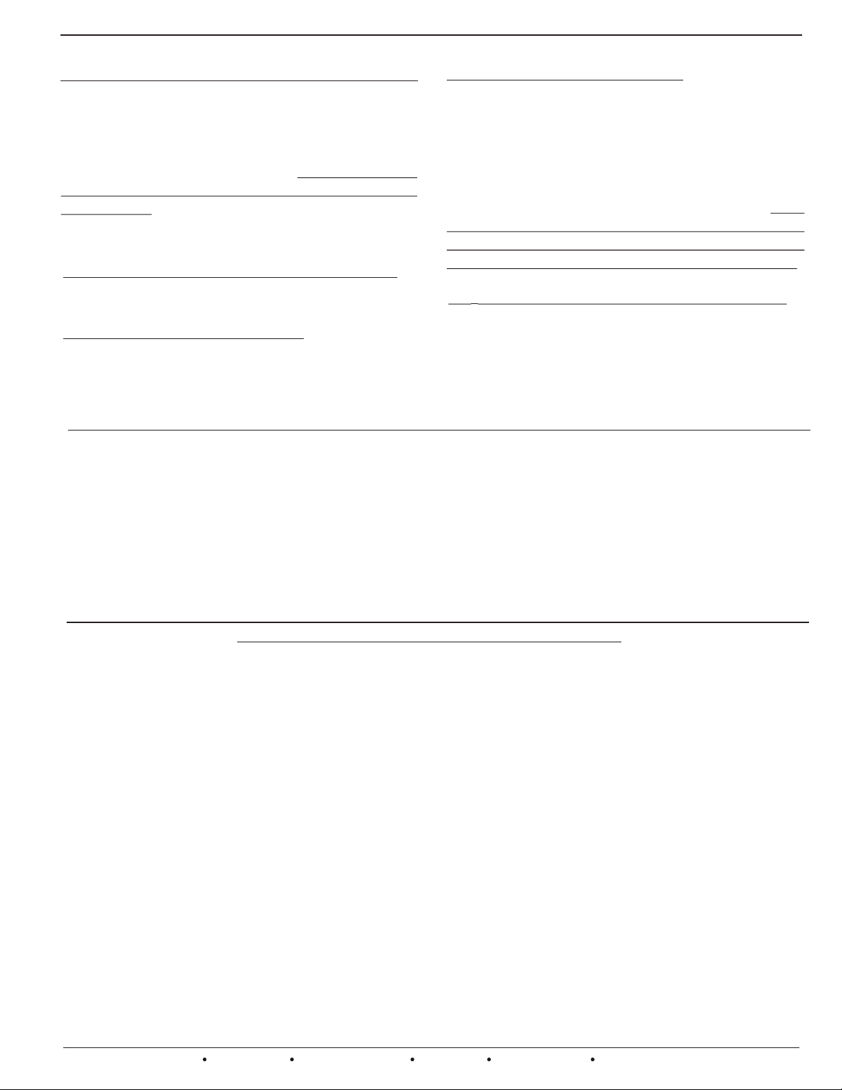
An On-Board Switch is provided that
allows the user to set the system to the
Emergency heat mode. This switch is
shown in the NORMAL position.
NOTE: An Emergency terminal is also
provided at every Thermostat terminal
block, allowing Heat Pump
Thermostats to be connected to every
zone.
The Adjustable Cooling Limit
potentiometer sets the supply air
temperature at which the 1st & 2nd
stage cooling is cycled off and the fan
continues to run, allowing the coil to
warm up.
The Adjustable Heating Limit
potentiometer sets the 1st or 2nd stage
heat supply air temperature, at which
the heating is cycled off and the fan
continues to run, allowing the heat
exchanger or coil to cool down.
The Adjustable Multistage Heat
differential potentiometer sets the 2nd
and/or, 3rd, & 4th stage heat supply air
temperature, at which the heating is
cycled off and the fan continues to run,
allowing the heat exchanger or coil to
cool down.
NOTE: Allows the supply air sensor to
be installed in the supply air plenum,
regardless of the coil/heat exchanger
configuration. Allows the installer to
fine tune virtually any multistage
heating system!
Momentarily pressing the TIMER
RESET button will clear any Active
Time Delay. This enables you to test
and certify the installation faster.
NOTE: Do not use sharp objects to
press the button. Use your finger tip or
the eraser head of a pencil.

UZC4 ADVANCED FIRMWARE AND HARDWARE FEATURES CONTINUEDUZC4 ADVANCED FIRMWARE AND HARDWARE FEATURES CONTINUED
*FIRE ALARM
INTERLOCK
FEATURE
Building
Code
Compliant
Support
Fire Alarm
Activation
Over-rides
ALL functions
and features
All Connected
Dampers will
close and the
HVAC system
will shut down
*Demand
Based
Ventilation
CO2 MONITOR &
FRESH AIR
INTERFACE
FEATURE
Building
Code
Compliant
Support
This feature is
not affected by
Heat/Cool
Operations
Fire Alarm
Activation
Over-rides
this feature
EWC Controls Inc. 385 Highway 33 Englishtown, NJ 07726 800-446-3110 FAX 732-446-5362 E-Mail- info@ewccontrols.com
The UZC4 includes a Fire Alarm
system interlock feature.
Wire the UZC4 into your building
Fire Alarm system, and achieve full
HVAC system shutdown, and
Closure of all Duct dampers, in the
event of Fire Mode Activation.
The circuit is normally closed and
must open to activate this mode. A
Fail Safe dry contact is required on
the Fire Alarm System.
When the Fire alarm system resets
to normal, the UZC4 will also
resume normal operation. Clip the
on-board jumper and wire as shown
on page 17.
The UZC4 includes a Carbon
Dioxide and Fresh Air interface
feature.
Wire the UZC4 up to a separate
CO2 Monitor with auxilary dry
contacts. When the CO2 Monitor
activates, the UZC4 will open a
fresh air damper connected to it’s
OA damper terminal block, and
start the HVAC system fan.
The circuit is normally open and
must close to activate this mode. A
normally open dry contact is
required on the C02 Monitor or
Fresh air Timer or Other Device.
When the CO2 monitor resets to a
normal CO2 level, the UZC4 will
close the fresh air /auxilary damper.
Other external dry contact devices
can be connected to the CO2
terminals such as a Manual Switch,
Enthalpy Control, or ClockTimer.
See page 16.
NOTE: Cooling & Heating
operations are not affected by
activation of this feature.
NOTE: Activation of the Fire Alarm
Interlock feature will over-ride the
CO2 Monitor feature.
AUXILARY or
DeHUMIDIFY
INTERFACE
RELAY
Enhanced
Comfort
Solution
Auxiliary “dry”
SPDT output
This feature is
affected by
Heat/Cool
Operations
Fire Alarm
Activation
Over-rides
this feature
ELECTRONIC
BYPASS
DAMPER
SUPPORT
FEATURE
Enhanced
Airflow
Solution
Fire Alarm
Activation
Over-rides
this feature
The UZC4 includes an Auxiliary
Interface Input and SPDT action
Dry Contact Output. This allows
the Installer to connect various
Auxiliary controls such as
Humidify or DeHumidify controls.
Simply connect the Controlled
Device or Circuit to the “Output”
dry contacts and achieve
integrated control without 3rd
party isolating relays.
See Page 14 and 15 for example
control and wiring solutions.
The Auxiliary input logic can be
field selected as (DA) Direct Acting
to humidify or (RA) Reverse Acting
to Dehumidify.
The UZC4 activates a unique algorithm to
rapidly de-humidify the home without
over-cooling it. See page 14.
The UZC4 includes support for
an Electronic Bypass Damper.
Wire up a EWC Model “EBD”
Bypass Damper to achieve
precise control of the HVAC
system static pressure and
bypass damper operations.
Wire up the Model “EBD” damper
as shown on page 17.
The UZC4 defaults the Bypass
Damper to the “Open” position
during “IDLE” periods. It will also
maintain that position for 45
seconds; at the start of any
thermostat demand for Heating,
Cooling, or Fan only Operation.
The 45 second time delay
allows a constant or variable
speed fan to start in a “Quiet
Mode” and does away with
noisy air duct velocities upon
system startup.
A Latent cooling effect is also
achieved by using this feature.
After 45 seconds the UZC4 will
release control of the system static
pressure to the EBD diaphragm
control and a gradual increase in
system static pressure is
achieved. NOTE: The UZC4 will not
resume control of the “EBD”, until the
next “IDLE” period begins.
3

UZC4 ADVANCED FIRMWARE AND HARDWARE FEATURES CONTINUEDUZC4 ADVANCED FIRMWARE AND HARDWARE FEATURES CONTINUED
RETURN AIR
MONITORING
FEATURE
Enhanced
HVAC System
Safety and
Energy
Savings
Solution
Note: If this
feature is
“Enabled”
but the “RAS” is
not connected or
is not detected;
The “RAS” LED
will blink rapidly
as a warning and
The UZC4 will
not allow RAS
operations to
occur.
Note: When the
Return Air sensor
detects a return
air temperature
between the
Stage Up Value
and
the Stage Down
Value, the “RAS”
LED will blink
slowly as a
warning. The UZC4
will also hold at the
current staging
until the system
status changes
sufficiently to
allow a stage up
or down.
The UZC4 includes a RETURN AIR TEMPERATURE SENSING feature.
Connect an OPTIONAL Return Air Sensor (#RAS) to the UZC4 and achieve the ability to
STAGE DOWN the HVAC system if the return air temperature exceeds the return air
temperature limit set points. Set the “RAS” Dipswitch #6 to the “ON” position, and
choose either (0) or (+10) at the “RA LIMIT” Dipswitch # 7. Both switches are located
on the Dipswitch Bank#2.
The UZC4 will now monitor the return air temperature and allow Stage up, or if necessary
Stage Down the cooling or heating operation to maintain a return air temperature within
the following values. As stated above, choose either (0) to accept the default return air
limit values for your particular HVAC system or choose (+10) to offset the default values
10 degrees higher. Note: The (+10) offset applies to heating operations only. The default
return air temperature limit set points for cooling operations cannot be offset.
RETURN AIR LIMITS DURING HEATING CYCLE FOR HEAT PUMPS ONLY:
Default (0) set points:
If the Return Air temperature is:
80 degree F. or below, Stage Up is allowed.
105 degree F. or above, Stage Down is forced.
Default (+10) set points:
If the Return Air temperature is:
90 degree F. or below, Stage Up is allowed.
115 degree F. or above, Stage Down is forced.
RETURN AIR LIMITS DURING HEATING CYCLES FOR GAS, OIL, STRAIGHT ELECTRIC:
Default (0) set points:
If the Return Air temperature is:
80 degree F. or below, Stage Up is allowed.
115 degree F. or above, Stage Down is forced.
Default (+10) set points:
If the Return Air temperature is:
90 degree F. or below, Stage Up is allowed.
125 degree F. or above, Stage Down is forced.
RETURN AIR LIMITS DURING COOLING CYCLES FOR ALL HVAC SYSTEM TYPES:
Default (0) set points:
If the Return Air temperature is:
65 degree F. or above, Stage Up is allowed.
55 degree F. or below, Stage Down is forced.
Default +10 applies to heating operations only.
The Return Air Sensing Feature cannot cycle the 1st stage equipment off-line. It can only force a
Stage Down when the equipment is in 2nd stage cool or 2nd, 3rd, or 4th stage heat, and the selected
return air set points above have been exceeded. The Supply Air Sensing feature is the only monitor
4
EWC Controls Inc. 385 Highway 33 Englishtown, NJ 07726 800-446-3110 FAX 732-446-5362 E-Mail- info@ewccontrols.com
that can cycle the 1st stage equipment off-line.
A three minute delay will occur after a forced stage down. If a stage up demand is present, the UZC4
will allow the stage up to re-occur when the three minute delay has expired and the return air
temperature is back to normal.
The UZC4 will automatically adapt to the “GAS,OIL,ELECTRIC” set points when a Heat Pump
system stages up to Fuel or Auxiliary mode.
This powerful feature will enhance the efficiency of your Zoned HVAC system and protect the
equipment from excessive bypass temperatures during low load conditions.
UZC4 ADVANCED FIRMWARE AND HARDWARE FEATURES CONTINUED UZC4 ADVANCED FIRMWARE AND HARDWARE FEATURES CONTINUED
MODULE TO MODULE FACTORY POWER WIRING
The UZC4 includes Factory Power Wiring on
all expanded systems. The 24 vac power to the
expansion modules is fed through the bus
cable. The bus cable feeds power to all module
processors & thermostats. Damper Motor
terminal blocks are isolated and powered
separately. This simplifies your wiring,
reduces the chances of polarity reversal and
allows more connected dampers per zone.
DIRECT DUAL FUEL COMPATIBLE FIRMWARE
The UZC4 is fully compatible with Dual Fuel
Heat Pumps, and other Hybrid HVAC systems.
Dual Fuel kits are not required. Select staging
based on Adjustable Time Delay, an Optional
Outside Air temperature Sensor, or allow the
thermostats to control staging. The intelligent
firmware does the rest.
* 7 TO 42 MINUTE STAGE UP TIME DELAY SETTINGS
RAPID DE-HUMIDIFY FIRMWARE
The UZC4 will perform a unique de-humidify
function when a demand to de-humidify is
detected at the Auxilary Input terminal. The
UZC4 will energize the Emergency heat relay to
activate one electric strip bank at the same
time the Y1 cool is active, so long as the
demand to de-humidify is detected. This
powerful feature will rapidly de-humidify your
home, and tempers (reheats) the supply air to
prevent over-cooling. See Page 14 for details.
CO2 DEMAND BASED VENTILATION SUPPORT
The UZC4 includes support for Demand Based
Ventilation Control scenarios. Designed to
help meet or exceed local building codes and
ASHRAE ventilation standards. Simply
connect your CO2 Monitor and a Fresh Air
damper to the UZC4.
*ZONE DEMAND LIMITING FEATURE
* 7 TO 42 DEGREE F. OUTSIDE AIR CHANGEOVER
* MULTI- STAGE HEAT ADJUSTABLE LIMIT CONTROL
* ELECTRONIC BYPASS DAMPER SUPPORT
* AUXILARY MULTI-FUNCTION SUPPORT RELAY
THERMOSTATIC DEMAND STAGE UP ON ALL ZONES
The UZC4 is the first Zone Control System to allow 4 stage thermostats to be connected to all zones
* STATUS LED’s ARE INCLUDED ON ALL MODULES
*ONE ZONE MODE SETBACK CAPABILITY
* SIMPLIFIED WIRING AND SYSTEM SETUP
* FIRE ALARM INTERFACE
The UZC4 is capable of numerous staging sequences depending on the type of HVAC system being
controlled, the type of thermostats connected, and the programmed staging sequence you desire.
As always you can still control a multi-stage HVAC system using inexpensive single stage thermostats
and sequence the staging by on-board adjustable time delay, or by using an optional outdoor air sensor
(OAS) and sequence the staging via an outdoor air set point.
You can still control a state of the art multi-stage Heat Pump using single or two stage conventional
thermostats and sequence the staging by time delay or outside air set point.
You can choose to control most any multi-stage Heat Pump or Conventional HVAC system with OEM
multi-stage thermostats on all zones. The UZC4 can be programmed to stage up or down based on the
thermostat inputs from each zone. The UZC4 allows a level of versatility that has never before been
offered by any zoning company. You can choose to install 3 or 4 stage thermostats on the largest zones, 2
stage thermostats on medium sized zones and single stage thermostats on the small zones.
To achieve staging via thermostatic demand only; Choose (TMR) Timer setting on Dipswitch #5 Bank 1
And then set the Multi-Stage Timer setting to (0) Zero. Setting the Timer to zero disables Timed Staging
and the UZC4 will stage up or down only when the thermostat(s) demand it.
EWC Controls Inc. 385 Highway 33 Englishtown, NJ 07726 800-446-3110 FAX 732-446-5362 E-Mail- info@ewccontrols.com
5
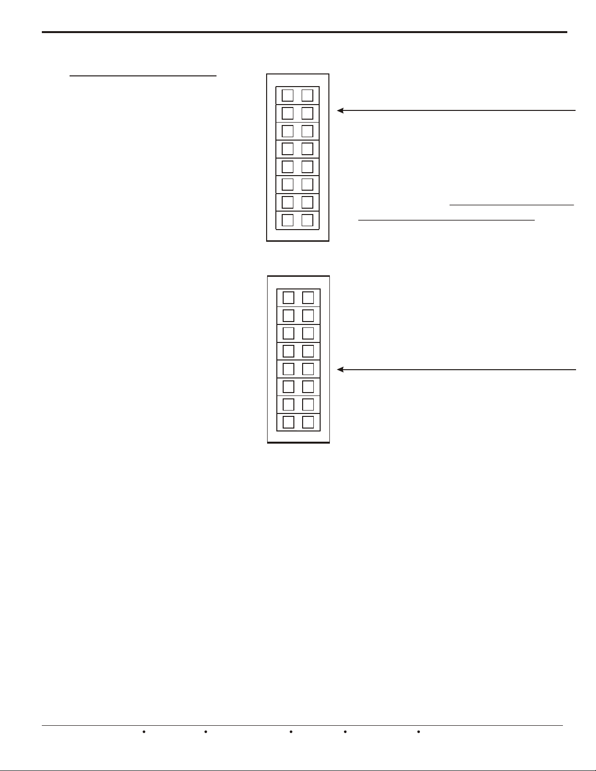
Selecting the Options Using the DIP Switches
***FS = Factory Settings
SWITCH LEGEND
FS HP < SYSTEM > GAS
DF < HP > CONV FS
FS OFF < FAN PRG > ON
90s < PURGE > 180s FS
OAS < STAGES > TMR FS
FS OFF < 50% R > ON
FS OFF < SAS > ON
FS GAS < FAN > HYDRO
HC < TSTATS > HPFS
FS1 < CS# > 2
FS O < RV > B
FS OFF < ZDL > ON
RA < AUX RLY > DA FS
FS OFF < RAS > ON
FS 0 < RA LIMIT > +10
FS ANY < FAN CTRL > Z1
Bank1
Bank2
RECORD YOUR DIP SWITCH
1
1
2
2
3
3
Programming and setting up the
UZC4 is very easy! Check the
4
4
5
5
6
6
7
7
8
8
Switch Legend and refer to the
following pages for an explanation of
each dip switch function and choose
your settings. Some functions may
not apply to your application. Use a
pencil to fill in the square & record
your settings. If the settings get
changed later on, you will have a
record of the original settings.
1
1
NOTE: When you choose “HP” at
switch #1, Bank 1, the fan mode is
2
2
3
3
4
4
5
5
6
6
7
7
8
8
automatically set for you. There is no
need to move switch #8, Bank1.
Leave it in the “GAS” factory setting.
RECORD YOUR DIP SWITCH
SETTINGS HERE
SETTINGS HERE
Detailed explanations of each Dip Switch Function are included on the following
pages. Please study and familiarize yourself with all of the functions and features, prior
to activating the Zoned HVAC system. Not all features will apply to your application.
The UZC4 comes from the factory pre-set to operate a 2 stage Heat Pump using
heat pump thermostats to control the staging.
Failure to properly set all dip switches to the correct and/or desired positions will result
in improper operation of the controlled HVAC System.
Please read and study the entire Technical Bulletin and if necessary, Call the EWC
Technical Support Hotline when assistance is required.
Leave this Technical Bulletin with the Home or Building Owner for future reference.
CONTINUED ON NEXT PAGE...
6
EWC Controls Inc. 385 Highway 33 Englishtown, NJ 07726 800-446-3110 FAX 732-446-5362 E-Mail- info@ewccontrols.com
Selecting the Options Using the DIP Switches - BANK1
HP < SYSTEM > GAS
1
Choose the type of HVAC system you want to control. Select HP, if your system is any type of heat pump. Select GAS,
if your system is a any type of Gas / Oil furnace, or any straight Electric furnace or Hydronic (hot water / steam)
heating system.
DF < HP > CONV
2
If you chose “HP” at switch #1, then choose the type of Heat Pump you want to control. Select DF, if your system is a Dual Fuel
heat pump with Gas or Oil furnace backup heat. Select CONV, if your system is a Conventional heat pump with Electric resistance
backup / supplemental heat. Also applies to Ground source / Geothermal heat pumps with Electric backup heat.
OFF < FAN PRG > ON
3
Select ON, if you want the UZC4 to force the indoor blower ON at the end of a heat/cool call to assist the zone purge cycle.
Selecting OFF will allow the HVAC system to operate the indoor blower, without interference from the UZC4.
90S < PURGE > 180S
4
Select 90S or 180S, if you want the zone dampers to hold position for 90 seconds or 180 seconds at the end of any heat or cool call.
This allows the HVAC system to purge the remaining hot or cold air, into the zone(s) that were calling for it.
OAS < STAGES > TMR
5
Select OAS, if you want to delay multi-stage operations based on the outside air temperature sensor. Select TIMER, if you want to
delay stage up based on the adjustable on-board timer. Both features are very useful when using single stage thermostats on all zones.
NOTE1: Y2/W2 stage up defaults to a 30 minute delay, when OAS is chosen. NOTE2: An optional Outside Air Sensor (Part#OAS) is required
to use the OAS feature. NOTE3: Thermostat demands to stage up, will always over-ride the Timer or OAS staging operations, Unless the
50% rule has been enabled, or the Return Air temperature limit has been exceeded. NOTE4: Thermostatic demands to Stage Down will be
honored unless the Timer is also in use. NOTE5: Disable the Timer by setting to OFF, and the UZC4 will obey Stage up & Stage down
demands via the thermostats only!
OFF < 50% RULE > ON
6
Select OFF, if you do not want to inhibit 2nd stage compressor cooling/heating operations based on the total number of zones calling.
Select ON, if you want to inhibit 2nd stage compressor cooling/heating operations based on the total number of zones calling. Half or more of
the total number of thermostats must be calling or stage up will not occur. NOTE 1: In All Modes, the 50% rule occurs between Y1 and Y2.
NOTE2: In Gas mode the 50% rule occurs between W1 &W2. NOTE3: Emergency mode is never affected by the 50% rule.
OFF < SAS > ON
7
Select OFF, if you do not want to use the Supply air sensor included with the UZC4 Zone Control system. Select ON, if
you want to use the included Supply air sensor. Refer to the data sheet included with the Supply air sensor for
installation details. Refer to page 2 for details on Supply air Sensing Limit Controls and settings. Mount the Supply
Air Sensor in the discharge duct and/or plenum.
GAS < FAN > HYDRONIC
8
Select GAS, if your HVAC system is a gas or oil forced air furnace. Select HYDRONIC, if your HVAC system has a hot
water / steam coil, or straight electric heat with no indoor blower support. Useful when you need the indoor blower to run
automatically in heat mode, just like it does in cool mode. NOTE: When you select HP on dip switch #1, the indoor fan
mode is automatically set for you. If so, then leave this switch in the factory GAS setting.
CONTINUED ON NEXT PAGE...
EWC Controls Inc. 385 Highway 33 Englishtown, NJ 07726 800-446-3110 FAX 732-446-5362 E-Mail- info@ewccontrols.com
7

Selecting the Options Using the DIP Switches - BANK2
1
HC < TSTAT > HP
Select the type of thermostats you want to use. Select HC, if your thermostats are the standard Heat/Cool type. Select HP, if your
thermostats are Heat Pump types. NOTE1: You cannot mix thermostat types. NOTE2: You do not need HP thermostats to control
a Heat Pump. NOTE3: Thermostat demands to stage up, will always over-ride the Timer or OAS staging operations, unless the 50%
rule has been enabled. NOTE4: Thermostatic demands to stage down will be honored unless the Timer is in use.
IMPORTANT NOTE: The UZC4 Zone Control System allows Heat Pump or Conventional Multi-Stage
thermostats to be wired to all Zones!
Thermostat demands to stage up, will always over-ride any programmed staging operation. The UZC4 will
remain in Multi-stage mode until that terminal is de-energized. If this occurs in dual fuel mode or emergency mode,
the UZC4 will stay in that mode until all Heating demands are satisfied. On the next heating cycle, the UZC4 will
attempt to activate 1st stage heat unless, Emergency Mode is still active, or the outdoor temperature is low and
OAS / DF has been selected. This comfort over-ride feature provides true versatility to your zoning system, and
gives the homeowner comfort control capability over the system.
1 < CS# > 2
2
Choose the number of Condensing Unit Stages you want to control. Select 1, if your CU has a Y1 connection only. Select 2, if
your CU has a Y1 & Y2 connection. NOTE1: This feature must be set correctly for proper Timed & Outdoor Air Sensor staging
operations. NOTE2: Thermostat demands to stage up, will always Over-ride the Timer & OAS staging operations, unless the
50% rule has been enabled, or the Return air temperature limit has been exceeded. NOTE3: All stage up Operations depend upon
the correct setting of this switch.
3
O < RV > B
Choose the type of Reversing Valve you want to control. Select O , if your heat pump reversing valve energizes in cooling and
defaults to heat mode. Select B, if your reversing valve energizes in heating and defaults to cool mode. NOTE: The UZC4 will hold
the “O” output or the “B” output continuously, even during idle periods, until a thermostatic demand to change modes is detected.
NOTE: Proper setting of this switch is critical. The reversing valve will not function properly if this switch is not set correctly.
OFF < ZDL > ON
4
Select ON and the UZC4 will limit HVAC operations based on the total number of zones calling for conditioned air.
16% or 1/6 of the total number of zones (rounded up) must be calling for the same mode of operation, or the UZC4 will not
activate the HVAC system. This feature only activates at 8 or more zones. Select OFF if you do not want to utilize the Zone
Demand Limiter feature. NOTE: Zone 1 is not affected by this feature. Zone 1 demands are always honored. ZDL example:
A zone system has 20 total zones and the ZDL feature is active; At least 4 zones must be calling for the same mode of
operation (Heat or Cool) or the UZC4 will not activate the HVAC system. 18zone=3, 16zone=3, 14zone=3, 12zone=2, 10zone=2, 8zone=2.
5
RA < AUX RLY > DA
Select the control signal type you need, in order to activate your preferred Auxilary Relay function. Choose RA (Reverse
Acting) for De-Humidification Control, or Choose DA (Direct Acting) for Humidification Control, depending on the control input signal
you require. Then connect your controlled device or circuit to the SPDT dry output contacts and achieve integrated control without
the need for 3rd party relays or specialty relays. If this feature is not used, the switch must be in the DA position.
See Pages 14-16 for further information.
6
OFF < RAS > ON
If you connect an OPTIONAL Return Air Sensor to the UZC4, then Select ON, and Choose to use the default set points
for Return Air Temperature Limit Operations, or choose to Offset those set points by 10 degrees higher at the next Dip Switch.
Refer to the data sheet included with the Return air sensor for installation details. Mount the Return Air Sensor in the
return air duct as close to the Blower intake as possible, or in the blower cabinet. Read page 4 for Operational details.
7
0 < RA LIMIT > +10
If you connect an OPTIONAL Return Air Sensor and switch on the “RAS” switch above; then choose “0” to accept the
default set points for Return Air Temperature Limits, or choose “+10” to Offset the default set points 10 degrees higher.
Refer to the data sheet included with the Return air sensor for installation details. Read page 4 for Operational details.
8
ANY < FAN CTRL > Z1
Select which thermostat(s) can activate a demand for Continuous Fan Operation. Choose “ANY”, and the UZC4 will
honor any thermostat demand to activate continuous fan, and only the dampers connected to that zone will open. All others
will close. Choose “Z1”, and the UZC4 will honor a demand to activate continuous fan from zone 1 only. All connected
dampers on all zones will open. Demands to activate continuous fan from any other thermostat will be ignored.
NOTE: Continuous Fan Operations will only occur when there are no active or pending heat or cool operations.
8
EWC Controls Inc. 385 Highway 33 Englishtown, NJ 07726 800-446-3110 FAX 732-446-5362 E-Mail- info@ewccontrols.com
 Loading...