

Page 1
Forced Air Zone Controls
®
APPLICATION NOTE
Model RD-HD, SID-HD, ND-HD
Bypass Volume Control Hand Damper
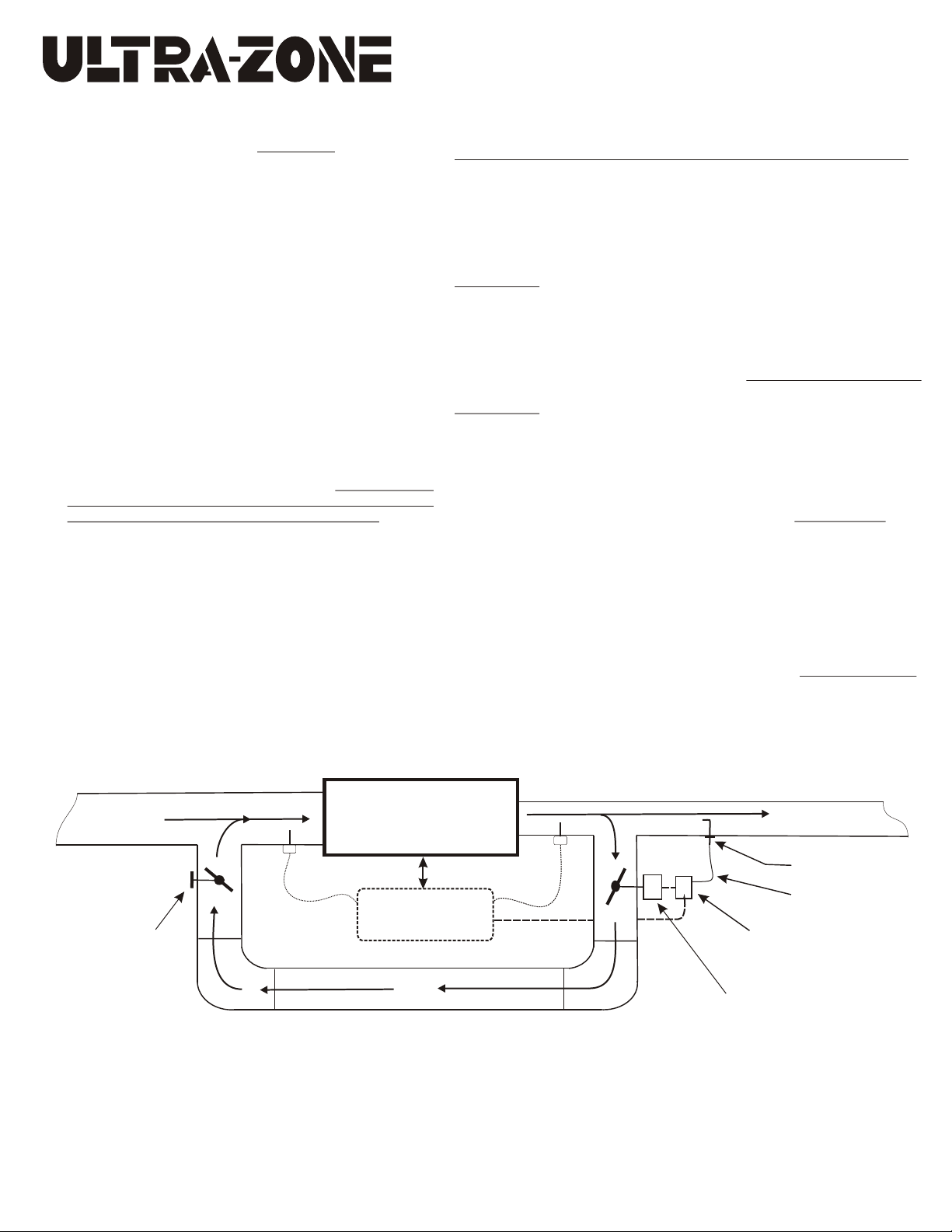
Pursuant to ACCA Manual Zr, install the Bypass Hand Damper in a
convenient location on the bypass duct before or after the actual bypass
damper. Allow at least 6 inches of clearance between both dampers.
Secure the assembly with sheet metal screws and seal all connections.
Insulate the entire bypass duct if necessary. Loosen the thumb screw on
the manual quadrant and test to make sure the blade moves freely in
both directions, then set the Bypass Hand Damper to the full open
position. Follow the instructions below.
• If you have a Manometer proceed to “Adjusting
the Bypass Hand Damper” Follow the directions for
setting the Bypass Hand Damper Delta P, based on
the Delta P (Total ESP) across the HVAC system.
• Setting the correct bypass differential pressure will
prevent the Bypass Duct from becoming the path of
least resistance and helps to:
*Eliminate DX coil freeze-up
*Eliminate Over-Heating
*Eliminate System Short Cycling
*Eliminate ECM Fan Motor Hunting
*Eliminate Bypass Damper Hunting
• If you don’t have a Manometer, simply adjust the
hand damper to the ½ closed position. EWC Controls
recommends at least ½ closed because setting some
value pressure drop is better than none at all.
See Figure 1.
• If during bypass mode, the Zone system Trips
excessively on the Supply air Sensor, you observe
Excessive Condensation on the bypass duct or Air
Handler, or you measure unusually low Differential
Temperatures, then close the Hand Damper some
more. If there is excessive noise through the bypass
duct, then open the Hand Damper a little.
• If you accidentally close the Hand Damper,
approximately 30% of the design bypass volume will
still flow through the Hand Damper due to the
truncated blade design. This unique design prohibits
adversely affecting the blower motor curve.
Adjusting the Bypass Hand Damper:
Before adjusting the hand damper, the installer should confirm the following:
(1) The zone system and all zone dampers are functioning properly.
(2) The HVAC System is functioning properly in highest (CFM) speed.
(3) Make sure all zone dampers are open and the Barometric or Electronic
Bypass damper is fully closed.
(4) Make sure the air filter is new or clean.
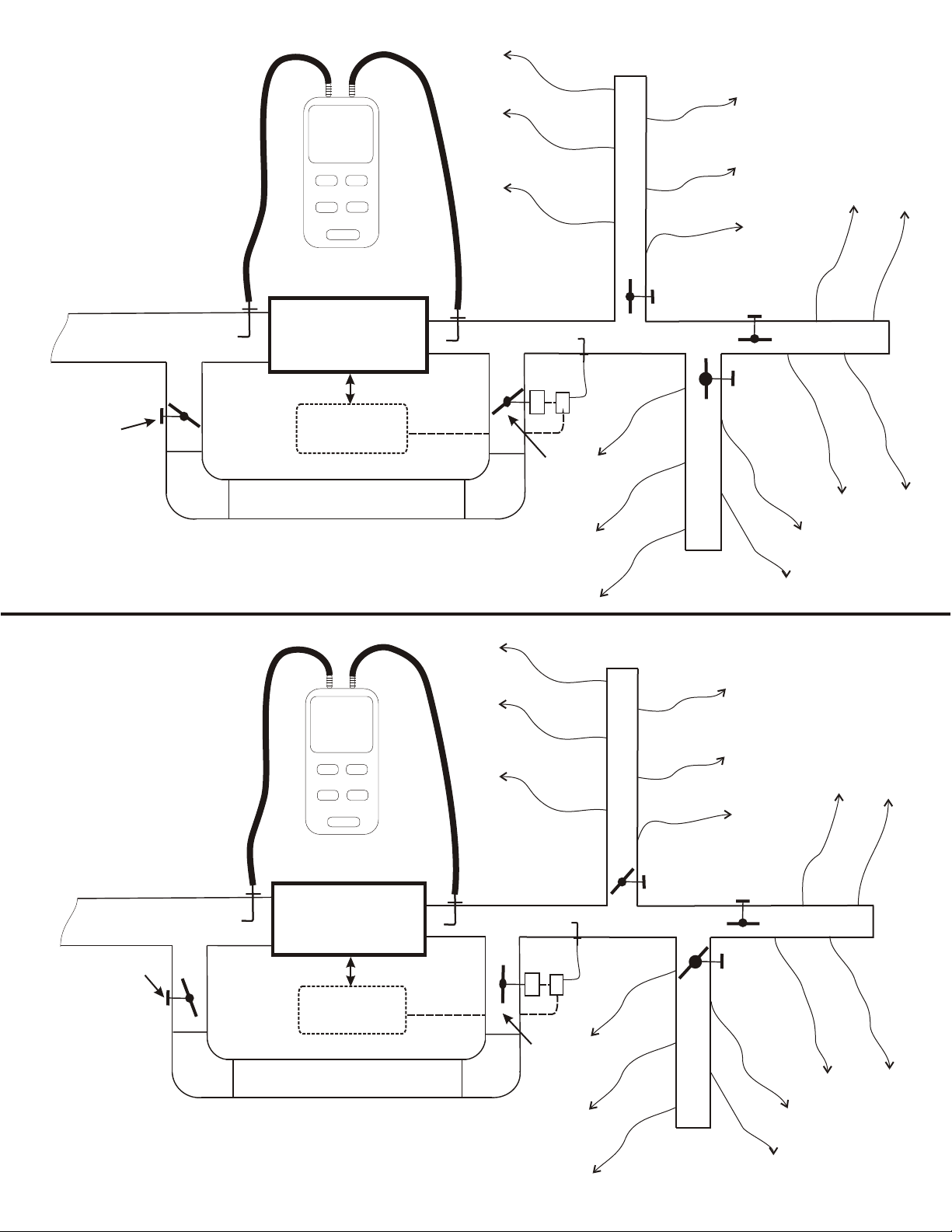
See Figure 2:
EXAMPLE - Measure the HVAC system Differential Pressure (Delta P) with
all zones calling and the bypass fully closed.
1. Measure the static pressure at the Supply Plenum (0.16”wc)
2. Measure the static pressure at the Return Plenum (-0.35”wc)
3. Observe the Delta P readout on the Manometer. (0.51”wc)
4. Or solve for Delta P = 0.16 - (-0.35) = 0.51”wc (Delta P Target to Match)
See Figure 3:
EXAMPLE - Measure the HVAC system Differential Pressure (Delta P) in the
worst case scenario (smallest zone calling and all other zones closed).
Bypass damper is forced open and the Hand damper is open.
1. Measure the static pressure at the Supply Plenum (0.29”wc)
2. Measure the static pressure at the Return Plenum (-0.15”wc)
3. Observe the Delta P readout on the Manometer. (0.44”wc)
4. Or solve for Delta P = 0.29 - (-0.15) = 0.44”wc Delta P (NO MATCH)
Adjust the Hand Damper (towards the closed position) and keep adjusting
until the Delta P readout on the Manometer reads the same or close to the
0.51”wc target above.
EXAMPLE - Measure again.
1. Measure the static pressure at the Supply Plenum (0.22”wc)
2. Measure the static pressure at the Return Plenum (-0.29”wc)
3. Observe the Delta P readout on the Manometer. (0.51”wc)
4. Or solve for Delta P = 0.22 - (-0.29) = 0.51”wc Delta P (Matches Target)
You are finished. Lock the Hand Damper in place. Release all forced Zone
dampers and place the Zone system and Thermostats back to normal operation.
NOTE: Values provided above are examples only. Your actual pressure readings will vary, but
the procedure will always be the same.
Return Air
from
All Zones
Ultra-Zone™
N
D
Excellence Without Compromise
E
D
H
-
D
R
D
H
-
D
I
S
D
-H
D
d
n
a
H
amp
Note: This EWC drawing of the Bypass damper, Hand Damper, Static Pressure control and Related duct work is intended to serve only as a guide.
Your actual duct work layout may differ. Use the graphic as a guide when planning or designing a Zone system regardless of the Equipment type,
Duct layout and Airflow configuration.
er
W
CONTROLS INC.
C
Figure 1
HVAC
UNIT
Return
Air
Sensor
(optional)
Ultra-Zone™
Zone Control
Panel
Supply
Air
Sensor
(required)
24vac Power
Control Wiring
385 Hwy. 33 Englishtown, NJ 07726
Ph: 800-446-3110 - Fx: 732-446-5362
P/N 090376A0169 REV. F 03.05.13
Copyright © 2011 EWC Controls Inc., All Rights Reserved.
Supply Air
to
Zone Dampers
Ultra-Zone™
Pitot Tube
M
P
Static Pressure Control
Ultra-Zone™
E
ua
t
c
A
otor
M
B
D
3/8” O.D.
Reference Tubing
Ultra-Zone™PS4
D
B
a
B
r
o
d
te
s
s
a
P
-
y
r
e
p
m
a
ic
r
t
me
o
r
Page 2
STEP 1: Place the system
into single zone scenario.
(All zones are calling and the
bypass is closed). If
necessary, use the hand
damper to close-off the
bypass completely.
Observe the Total ESP
value at the bottom of the
Manometer or do the math
yourself. Record the value.
That value is now the target
Example values
Your values will vary
P2
P1
0.16
ESP
0.51
P1/P2
HOLD
ON/OFF
UNIT
ZERO
WC
Figure 2
P1
Excellence Without Compromis
W
E
CONTROLS INC.
e
C
Return Air
from
All Zones
Close for
Step1
Example values
Your values will vary
P1 = 0.16
P2 = -0.35
0.16 - (-0.35) = 0.51”wc
STEP 2: Place the system
into worst case scenario.
(Smallest zone calling, all other
zones closed).
Force the bypass damper to
The full open position & open
the hand damper as well.
Start closing the bypass hand
damper until the Delta P
value matches the target
value obtained in Step #1.
When finished, lock it down
and place the system back to
normal operation.
Return Air
from
All Zones
Z3
HVAC
UNIT
Z2
Z1
M
Ultra-Zone™
Zone Control
Panel
WC
P1
0.21
ESP
0.51
P1/P2
UNIT
HOLD
ZERO
ON/OFF
P2
HVAC
UNIT
24vac Power
Control Wiring
P1
P
Close for
Step1
Figure 3
Z3
Excellence Without Compromis
W
E
CONTROLS INC.
Z2
e
C
Adjust this damper
towards closed
until the Delta P
(ESP) value
matches Step 1.
Example values
Your values will vary
P1 = 0.21
P2 = -0.30
0.21 - (-0.30) = 0.51”wc
Ultra-Zone™
Zone Control
Panel
24vac Power
Control Wiring
M
P
Force Open
during Step 2
only
Z1
P/N 090376A0169 REV. F 03.05.13
Copyright © 2011 EWC Controls Inc., All Rights Reserved.
 Loading...