

Page 1
TECHNICAL BULLETIN
Model PRD
Barometric By-Pass Damper
Leave this bulletin on the job site for future reference!
GENERAL DESCRIPTION
The model PRD pressure regulating damper is a single blade rectangular barometric
damper with a counter balanced weighted arm. The PRD is an economical way of
bypassing excess air when zone dampers close. Damper adjustment is done by
moving the weight up and down the arm and by off-setting the arm. See Page 2 for
details.
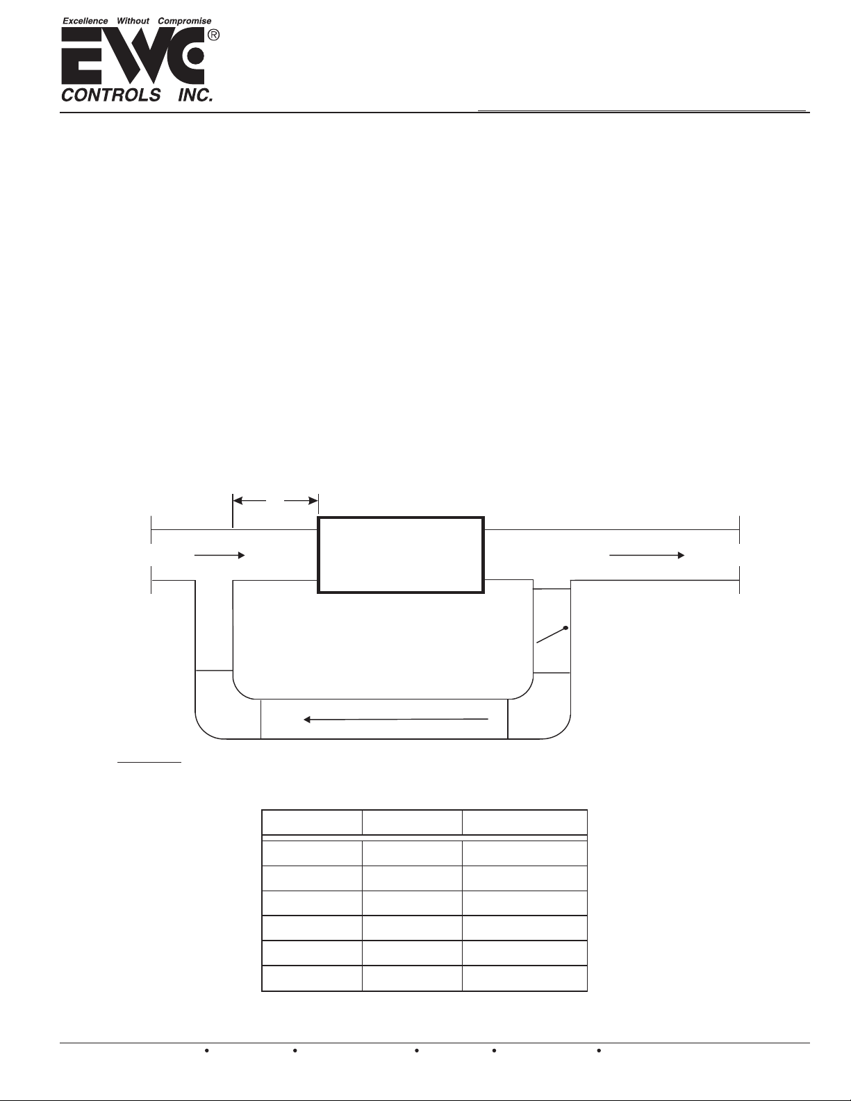
The PRD is installed in the By-Pass ductwork to regulate the excess air pressure. The
damper can be mounted to relieve the pressure by returning the air back to the return
air duct (See Figure 1) or by dumping it into a non-critical conditioned area.
The PRD is an ideal By-Pass solution for any Constant Speed or Variable Speed
system up to 5 ton capacity.
Bypass Damper Assembly
6’
Return air Supply air
FIGURE 1
HVAC
UNIT
PRD or PRD-RD
Model numbers, sizes available and amount of CFM bypass
MODEL # SIZE W x H
PRD 12 x 8
12" x 8"
BYPASS CFM*
1,000 CFM
TB-224
EWC Controls Inc. 385 Highway 33 Englishtown, NJ 07726 800-446-3110 FAX 732-446-5362 E-Mail- [email protected]
P/N 090375A0224 REV. H
PRD 12 x 10
PRD 12 x 12
PRD 20 x 8
PRD 20 x 10
PRD 20 x 12
*By-Pass CFM is determined at 0.3” w.c. Friction per 100’ of ductwork
Copyright 2006-2008 EWC Controls All Rights Reserved©
12" x 10"
12" x 12"
20" x 8"
20" x 10"
20" x 12"
1,200 CFM
1,400 CFM
1,600 CFM
2,000 CFM
3,000 CFM
1
Page 2

BY-PASS SIZING CALCULATIONS
1.
Start with the system’s Total C.F.M.
2.
Calculate the C.F.M. for the smallest zone that can run by itself.
3.
Subtract the Total C.F.M. from the Smallest Zone C.F.M.
The left over amount is the By-Pass C.F.M. Refer the By-Pass C.F.M. to the chart on Page 1, match to the
closest size. DO NOT Undersize the By-Pass Damper. The By-Pass can also be sized on a Duct Calculator
at 0.3”w.c. Friction per 100ft of Duct. (For quieter By-Pass operation, size the By-Pass Damper at a lower
Friction Value).
EXAMPLE: 5 ton system @ 400 C.F.M. Per ton = 2000 C.F.M 2000 C.F.M.
Subtract Smallest Zone = 500 C.F.M. -500 C.F.M.
1500 C.F.M.
1500 C.F.M. @ 0.3” Friction per 100ft. of duct = PRD 20 x 8
BAROMETRIC BY-PASS SET-UP PROCEDURE
The PRD must be installed horizontal & level between the supply duct and the return duct.
1.
Position PRD door to open in the direction of your airflow by forcing it over the stop.
2.
Make the PRD connection on the return so that the bypass air has a minimum 6 feet of return duct before it
3.
enters the air handler, if space permits. If not do your best.
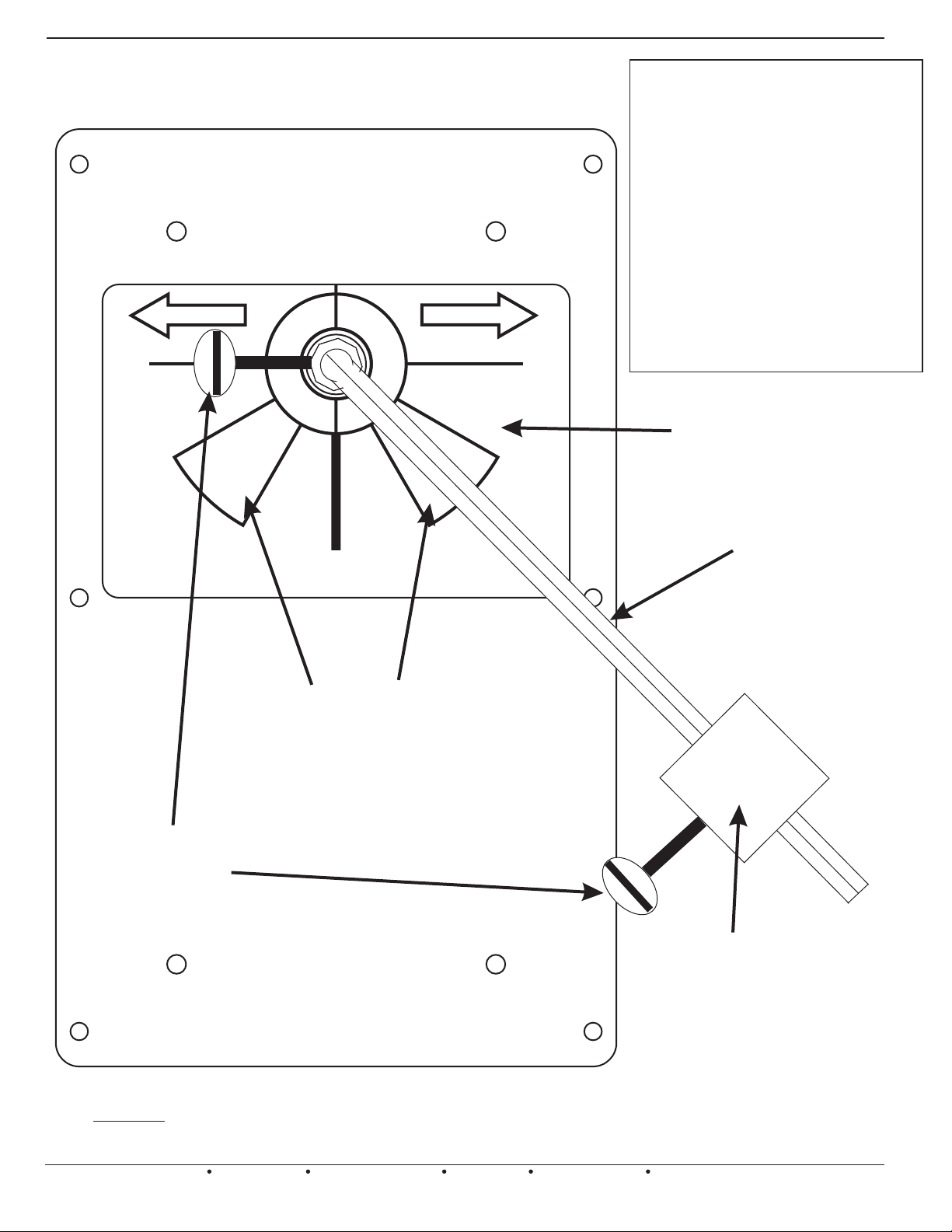
Position ARM in the “IDEAL ARM LOCATION” for the direction of your air flow and tighten the THUMB
4.
SCREW. (Refer to Page 4)
Position the WEIGHT high up on the ARM and tighten the THUMB SCREW
5.
Energize ALL Zones to operate the unit with the Fan running on the Highest speed (Usually a Cooling
demand, 2nd stage if applicable).
Return to the PRD & reposition the WEIGHT lower on the ARM until the PRD just closes completely. (It
6.
should be closed to the point where any additional force will open the PRD).
Turn off all Zones but the Smallest Zone & Wait about 45 seconds.
7.
Monitor the airflow for the Smallest Zone. Is there to much Velocity? Proceed to Step 9.
8.
Is there insufficient Velocity? Proceed to Step 10.
Is the Velocity acceptable? Proceed to Step 11.
To Much Velocity: Reposition the WEIGHT Higher up on the ARM until the velocity has subsided to an
9.
adequate level. If the velocity remains to high, reposition the ARM towards ‘6’ on the scale. Proceed to Step
11.
If the velocity is still an issue, double check your By-Pass size, calculations are on Page 1.
Insufficient Velocity: Reposition the WEIGHT Lower on the ARM until the velocity is at an acceptable
10.
level. If the velocity remains to low, reposition the ARM towards the ‘9’ or ‘3’ on the scale (Depending on
the direction of airflow). Proceed to Step 11.
If velocity still remains low for the Smallest zone, to much air is being forced through the PRD, an Electronic
By-Pass Damper (Model EBD) may need to be considered. Contact Technical Support.
Congratulations, your PRD By-Pass damper is now properly set-up.
11.
2
EWC Controls Inc. 385 Highway 33 Englishtown, NJ 07726 800-446-3110 FAX 732-446-5362 E-Mail- [email protected]
Page 3
9
AIRFLOW
8
IDE
A
L
A
LOCATI
BAROMETRIC BY-PASS SET-UP PROCEDURE
The direction of airflow can
be reversed on the PRD if
necessary, by pushing the
Door over the stop on the
bottom of the damper
frame. Then, adjust the arm
to the proper position based
on the new airflow direction.
Contact EWC Controls Inc.,
Te c h n i c a l s u p p o r t i f
AIRFLOW
neces sa ry fo r furth er
details.
3
GRADUATED
I
DEAL
M
R
N
O
LOCA
A
RM
T
I
O
N
4
ADJUSTMENT
SCALE
POSITION ARM IN IDEAL LOCATION IF
7
AIR FLOW IS IN DIRECTION INDICATED
BY THE ARROW ABOVE
LOCATION
THUMB
SCREWS
POSITION ARM IN IDEAL LOCATION IF
AIR FLOW IS IN DIRECTION INDICATED
6
IDEAL
ARM
5
BY THE ARROW ABOVE
ARM
WEIGHT
FIGURE 2
EWC Controls Inc. 385 Highway 33 Englishtown, NJ 07726 800-446-3110 FAX 732-446-5362 E-Mail- [email protected]
3
Page 4
BAROMETRIC BY-PASS DAMPER
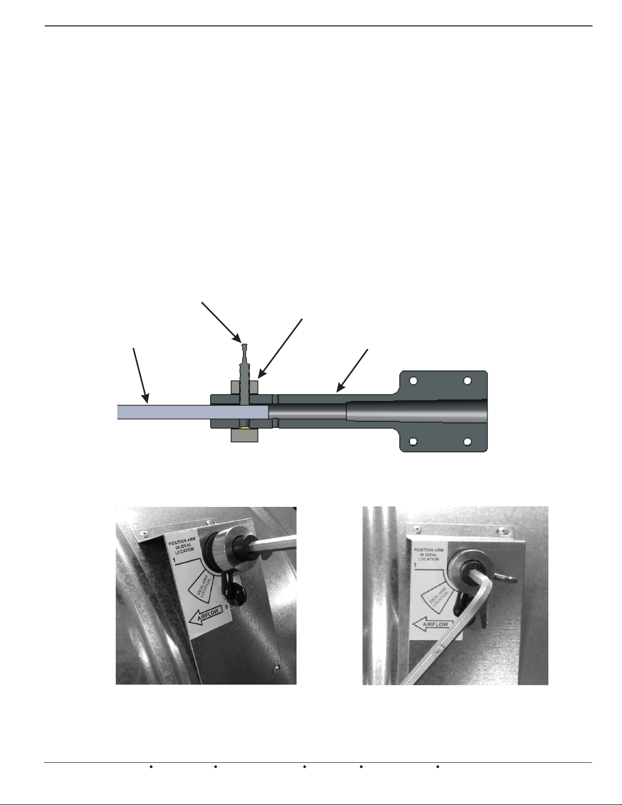
ASSEMBLY OF PRD & PRD-RD BY-PASS DAMPER
1 - INSTALL BY-PASS DAMPER PER INSTRUCTIONS ON PAGE 2.
2 - SLIDE LOCKING-COLLAR OVER DAMPER SHAFT.
3 - INSERT HEX ARM INTO DAMPER SHAFT.
4 - ALIGN LOCKING-COLLAR THUMB SCREW WITH ONE OF THE 4 HOLES ON THE DAMPER
SHAFT WHILE HOLDING ARM AT THE DESIRED ANGLE.
5 - TIGHTEN THUMB SCREW TO SECURE HEX ARM IN PLACE.
6 - POSITION WEIGHT ON HEX ARM AND TIGHTEN THUMB SCREW TO SECURE IN PLACE.
7 - REFER TO PAGE 2 FOR SET-UP PROCEDURE.
THUMB SCREW
LOCKING-COLLAR
HEX-ARM
DAMPER SHAFT
FIGURE 3 -- CUT AWAY VIEW OF ASSEMBLY
FIGURE 4 -- CLOSE-UP VIEWS OF ASSEMBLY
4
EWC Controls Inc. 385 Highway 33 Englishtown, NJ 07726 800-446-3110 FAX 732-446-5362 E-Mail- [email protected]
 Loading...