

EWC Controls EWT-3900 Technical Bulletin
TECHNICAL BULLETIN
Model EWT-3900
Wireless Programmable Digital Thermostat
Installer : Save these instructions for future use!
FAILURE TO READ AND FOLLOW INSTRUCTIONS CAREFULLY BEFORE INSTALLATION OR
OPERATION COULD DAMAGE THIS CONTROL OR CAUSE PROPERTY DAMAGE.
DESCRIPTION
The EWT-3900 7Day/5-2 Day Wireless Programmable
Digital Solid State Thermostat uses a microcomputer to
provide precise time and temperature control. This wireless
thermostat offers additional flexibility to design heating and
cooling systems where hard wired installations would be
difficult to do.
The Model EWT-3900 Wireless Thermostat is Linked to
the Receiver at the factory. Simply power up the
Receiver, then program and operate the Thermostat.
Features:
l The Thermostat is powered by a rechargeable lithium-ion
battery.
l The receiver module is powered with 24VAC from a
Control Panel or 24VAC Class 2 Transformer.
l The receiver module terminal block has the following
terminals: R, C, W1/E, W2, Y1, Y2, G, O, B and one
NC (no connection) terminal.
l Compatible Equipment: ULTRA-ZONE Control Panels:
NCM-300, BMPlus3000 & UZC-4.
Single or two stage heating and cooling equipment
Gas, Electric, Oil or Hydronic. One or two stage
compressor heat pump with electric backup.
l Simultaneous heat and cool program storage.
l Program storage is retained in case of power loss.
l LCD continuously displays time and room temperature.
Temperature set point is displayed when it is being
changed.
l Temperature display can be configured in °F or °C.
l The Thermostat can be programmed between
45°F and 95°F.
l Backlit display.
l Air Filter Replacement Monitor.
Electrical Ratings
19-30VAC 50/60 Hz
1.0 Amp (Max load per terminal)
MON
1
DAY/
TIME
PROG
Room
PROG
:
DAY
°
PM
FAN
SYSTEM
HEAT
FAN
AUTO
MODE
HOLD
/RUN
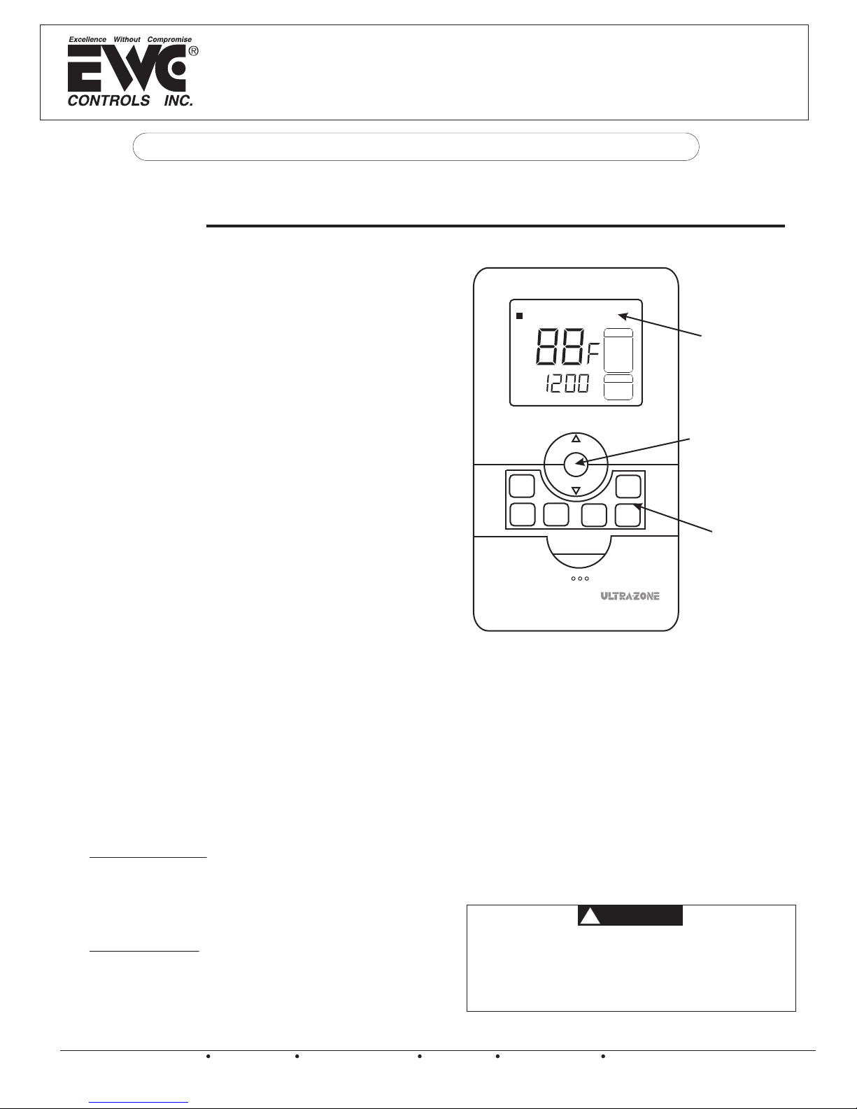
LCD Display: Shows
Time, Day, Temperature
and other system data.
Reviews filter usage
in hours and minutes
and also activates
standby mode.
Soft touch Programming
and Function Buttons
Figure 1
Contents:
1 EWT 3900 Thermostat
1 EWT 3900 Receiver
1 USB Adapter Cord
6 Plastic Wall Anchors
6 #8 x 1” Screws
1 TB-236 Technical Bulletin
Accessories: (not included)
EWT-BC Wall Outlet Charger
Replacement Battery
Replacement Charging Cord
Charging Requirements:
EWT-BC Wall Outlet Charger
PC Computer with USB Port
or
Thermal Ratings
Set point Temperature Range 45°F to 95°F
Operating Ambient Temperature Range 30°F to 99°F
Storage Temperature Range 14°F to 140°F
Operating Humidity Range 0-90% R.H. (Non Condensing)
TB-236 090375A0236 Rev. B
EWC Controls Inc. 385 Highway 33 Englishtown, NJ 07726 800-446-3110 FAX 732-446-5362 E-Mail- info@ewccontrols.com
Copyright © 2009 EWC Controls All Rights Reserved
ATTENTION
!
This product does not contain mercury. However, this
product may replace a unit which contains mercury.
EWC Controls Inc. would like to advise all technicians
and consumers that all mercury thermostats should
be recycled.
1
INSTALLATION
The installer should be an experienced and trained
HVAC contractor. Failure to read and follow
instructions carefully before installation or
operation could damage this control or cause
property damage. Test the finished installation for
proper operation.
To conserve power, the EWT-3900 leaves the
factory in Standby Mode. When removed from
the box, “PE” will be displayed on the LCD to
indicate Standby Mode. When you are ready to
use the thermostat, press and hold the
round center button for five seconds to exit
Standby Mode.
CAUTION
!
To prevent electrical shock and/or equipment damage,
disconnect electric power to HVAC system at main
fuse or circuit breaker box until installation is complete.
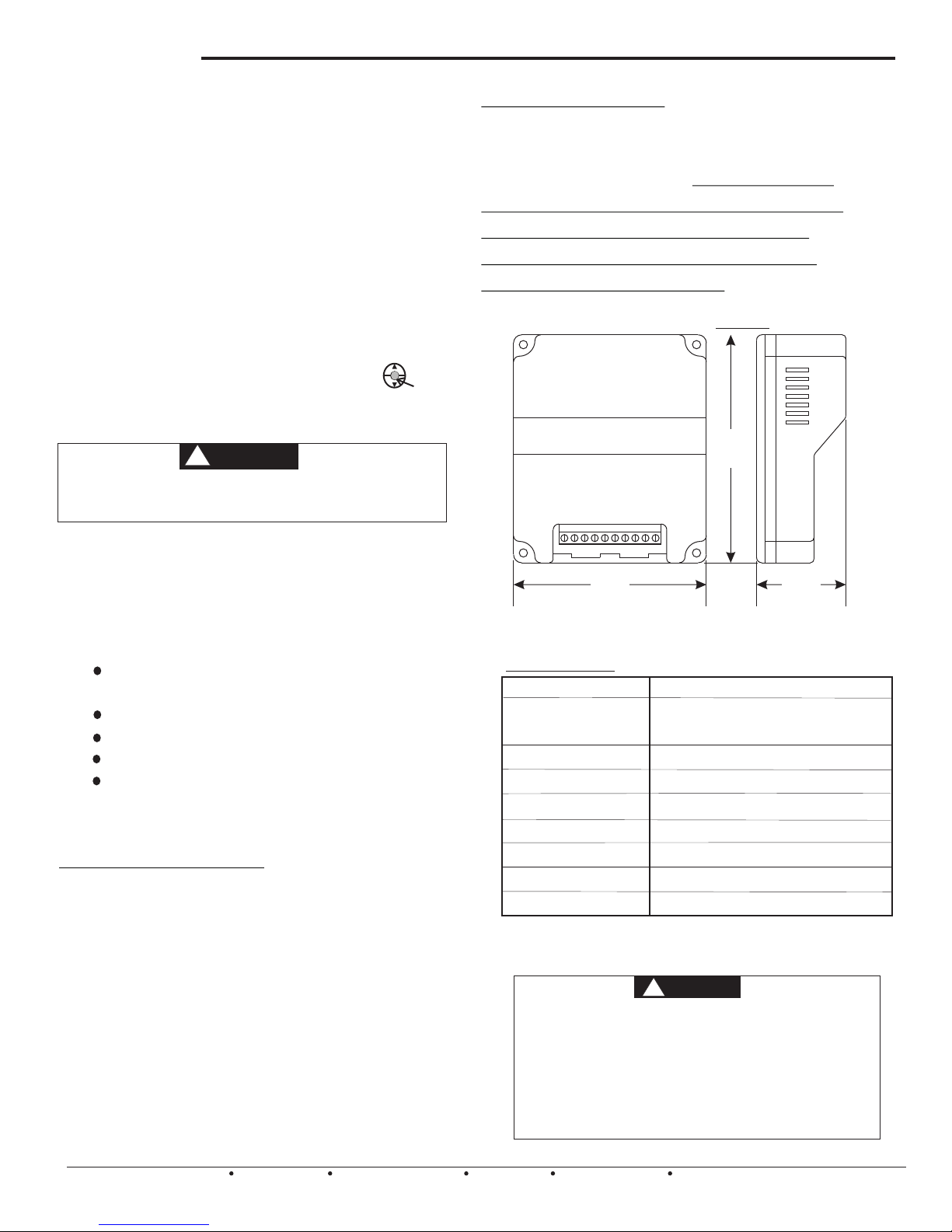
Mounting the Receiver
Mount the receiver with the supplied mounting
screws near the zone control panel or HVAC
equipment to be controlled. Do not mount the
receiver inside the equipment cabinet or any
other metal enclosure. Do not Mount the
receiver in any location than is subject to
freezing and/or condensation.
4.55”
W1
2
W2
C
R
E/
NC
B
Y1
Y
O
G
Mount the EWT-3900 Thermostat about 5 feet
above the floor in an area with good air circulation
and average temperature. DO NOT install the
thermostat where it can be affected by:
drafts or dead spots behind doors and in
corners
hot or cold air from ducts
radiant heat from sun or appliances
concealed pipes and chimneys
on surfaces such as an outside wall, that
are a different temperature than the room
air temperature.
Mounting the Thermostat
ATTACH THE MOUNTING BRACKET TO THE WALL
1. Place the bracket on the wall where you would like
the thermostat to be and mark the two holes with a
pencil.
2. Using a 3/16” drill bit, drill out the marks you just
made on the wall.
3. Insert the wall anchors into the holes pressing flush
with the wall.
4. Place the bracket over the holes and fasten with the
supplied #8 screws.
3.85”
1.78”
Technical Data
Power
Working Environment
Range
Shell
Dimension
Connection Interface
Wireless Frequency
Communication baud rate
Wireless Channels
Communication Distance
Do not use circuits exceeding specified voltage. Higher
voltage will damage control and could cause shock or
fire hazard.
Do not short out terminals on gas valve or primary control
to test. Shorted or incorrect wiring will damage thermostat
and could cause personal injury and/or property damage.
Thermostat installation and all components of the system
shall conform to Class 2 circuits per the NEC code.
AC24V, 50/60Hz
30°F~99°F
0~90%RH(non-condensing)
Fire Retardant PC ABS
4.55x3.85x1.78 in (HxWxD)
Each terminal is capable of accepting
2 x 18 AWG solid copper wires.
433MHz
2.4 kbps
1~10 Channels
Beeline distance 200ft in the field. (The
distance will shorten through walls and floors)
WARNING
!
2
EWC Controls Inc. 385 Highway 33 Englishtown, NJ 07726 800-446-3110 FAX 732-446-5362 E-Mail- info@ewccontrols.com
Copyright © 2009 EWC Controls All Rights Reserved
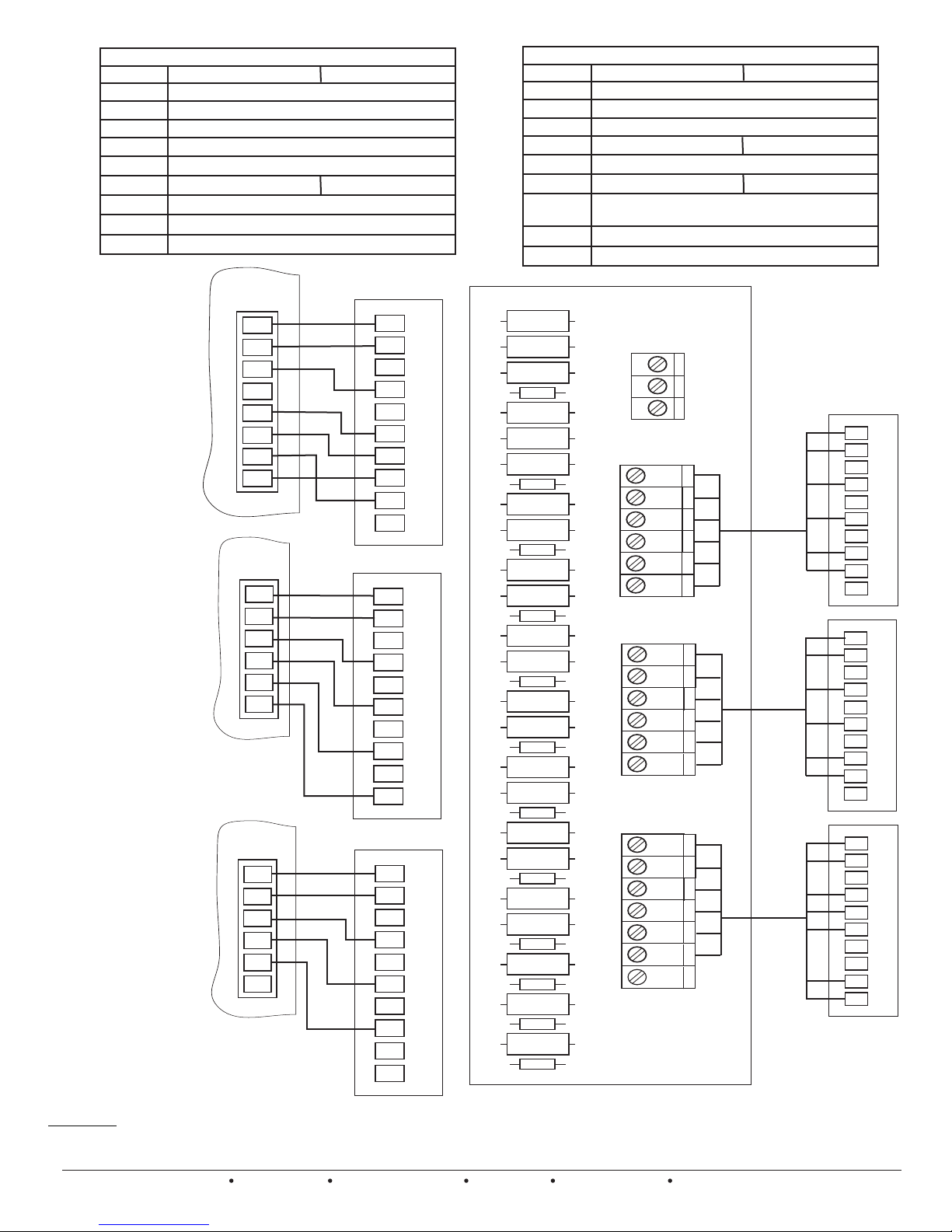
WIRING THE RECEIVER TO THE EQUIPMENT
THERMOSTAT TERMINALS (HEAT PUMP)
SYSTEM
C
R
E/W1
W2
Y1
Y2
G
O
B
Heat Pump 1
24 Volt (Common)
24 Volt (hot)
Emergency 1st stage
Auxiliary / Emergency 2nd Stage
Heat and Cool mode 1st stage (compressor)
No output
Blower/Fan Energized on call for Heat and Cool
Energized in Cool Mode
Energized in Heat Mode
Heat Pump 2
2nd Stage Compressor
THERMOSTAT TERMINALS (CONVENTIONAL)
SYSTEM
C
R
E/W1
W2
Y1
Y2
G
O
B
Single Stage
24 Volt (Common)
24 Volt (hot)
Heat Mode 1st stage
No Output
Cool mode 1st stage (compressor)
No output
Blower/Fan Energized on call for Cool (and Heat
if HE was selected)
No Output
No Output
Multistage
Heat Mode 2nd stage
2nd Stage Compressor
UZC-4
Heat Pump 3H/2C
O Reversing Valve
Figure 2
BmPlus 3000
Heat Pump 2H/1C
B Reversing Valve
Figure 3
NCM-300
Gas/Elec. 1H/1C
Figure 4
ZONE
T’STAT
C
R
W1/E
W2
Y1
Y2
O/B
G
ZONE
T’STAT
C
R
W/E
Y
G
O/B
ZONE
T’STAT
C
R
W/E
Y
G
O/B
C
R
NC
E/W1
W2
Y1
Y2
G
O
B
C
R
NC
E/W1
W2
Y1
Y2
G
O
B
C
R
NC
E/W1
W2
Y1
Y2
G
O
B
r
ive
e
c
Re
r
ve
i
ce
e
R
r
e
v
i
e
c
Re
R5
R10
R9
R6
R70
R69
R13
R19
R23
R24
R25
R29
R30
R34
R32
R33
R40
R39
R42
R43
R41
R44
R47
R49
R48
R48
R54
R55
R54
R55
R50
R61
R63
R62
R65
SUPPLY
AIR
SENSOR
ZONE 3
T'STAT
W/E
C
W/E
O/B
Y
R
G
ZONE 2
T'STAT
W/E
C
W/E
O/B
Y
R
G
ZONE 1
ZONE 1
T'STAT
T'STAT
W/E
C
W/E
O/B
Y
R
G
ONE
ZONE
Figure 5
FULLY
ZONED
NCM-3000
2
1
C
R
NC
r
e
E/W1
v
i
W2
e
Y1
Y2
Rec
G
O
B
C
R
NC
er
E/W1
v
i
W2
e
Y1
ec
Y2
R
G
O
B
C
R
RC
02
E
1
O/B
Y2
3
L
WTE
Y
G
AUX
For detailed wiring info
refer to NCM-300 TB-226
Warning: There should be at least 1 hardwired system thermostat in the home or building to ensure the
ability to control the HVAC equipment in the event of a drained battery or loss of communication.
EWC Controls Inc. 385 Highway 33 Englishtown, NJ 07726 800-446-3110 FAX 732-446-5362 E-Mail- info@ewccontrols.com
Copyright © 2009 EWC Controls All Rights Reserved
3
 Loading...