

TECHNICAL BULLETIN
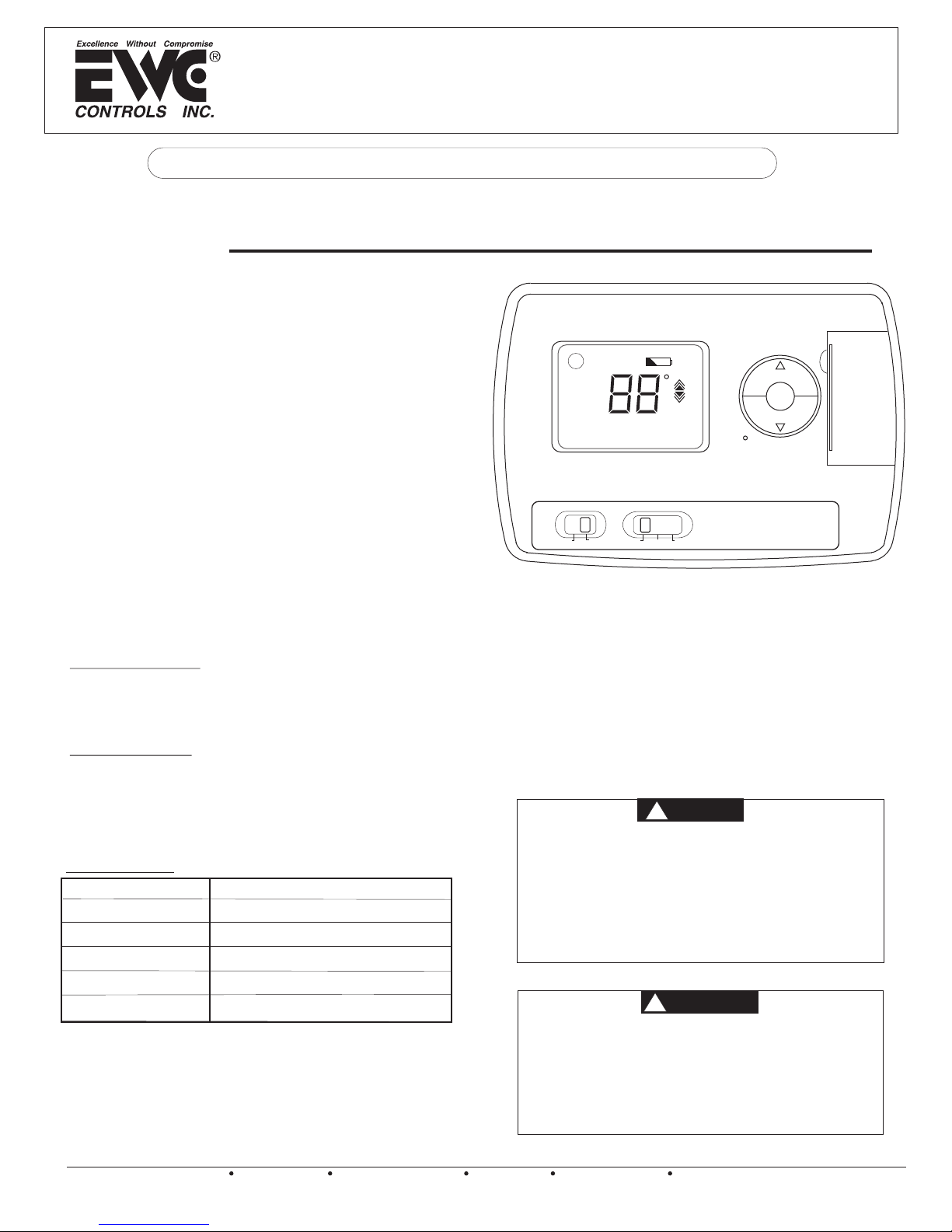
Model EWT-3611
Non-Programmable Digital Thermostat
Installer : Save these instructions for future use!
FAILURE TO READ AND FOLLOW INSTRUCTIONS CAREFULLY BEFORE INSTALLING OR
OPERATING THIS CONTROL COULD CAUSE PERSONAL INJURY OR PROPERTY DAMAGE.
DESCRIPTION
The EWT-3611 is a Non-Programmable Digital Solid State
Thermostat.
Features:
FILTER
l The Thermostat shall be powered by 24 vac and with a
AA battery as backup.
l Compatible Equipment: ULTRA-ZONE Control Panels:
F
SET
TEMP
ST-2E/3E, NCM-300, BMPlus3000 & UZC-4.
COOL
Single Stage Heating and Single Stage Cooling
HEAT
Equipment. Gas, Electric, Oil or Hydronic.
l LCD continuously displays room temperature.
Temperature set point is displayed when it is being
changed.
fan
l Temperature display can be configured in °F or °C.
l The Thermostat can be set between 45°F and 95°F.
on
auto
l Backlit display.
l The thermostat terminal block has the following
terminals: Y, R, G, W, RC/O, RH/B and C.
(Shown with Front Cover Removed)
lAir Filter Replacement Monitor.
Contents:
Electrical Ratings
19-30VAC 60 Hz
1.0 Amp (Max load per terminal)
1 EWT-3611 Thermostat
2 Plastic Wall Anchors
2 #8 x 1” Screws
1 TB-234 Technical Bulletin
Thermal Ratings
Set point Temperature Range 45°F to 95°F
Operating Ambient Temperature 30°F to 99°F
Storage Temperature Range 14°F to 140°F
Do not use circuits exceeding specified voltage. Higher
voltage will damage control and could cause shock or
Technical Data
Power
Working Environment
Range
Shell
Dimension
Connection Interface
24VAC, 50/60Hz + AA Battery
32°F~120°F
5~95%RH(non-condensing)
Fire Retardant PC ABS
3.5x5.1x1.2 in (HxWxD)
Each terminal is capable of accepting
2 x 18 AWG solid copper wires.
fire hazard.
Do not short out terminals on gas valve or primary control
to test. Shorted or incorrect wiring will damage thermostat
and could cause personal injury and/or property damage.
Thermostat installation and all components of the system
shall conform to Class 2 circuits per the NEC code.
This product does not contain mercury. However, this
product may replace a unit which contains mercury.
EWC Controls Inc. would like to advise all technicians
and consumers that all mercury thermostats should
be recycled. You can take your mercury thermostat
to your local HVAC wholesaler for recycling.
SPAN
system
cool
off
heat
WARNING
!
ATTENTION
!
Reset
Fig. 1
TB-234 090375A0234 Rev. B
EWC Controls Inc. 385 Highway 33 Englishtown, NJ 07726 800-446-3110 FAX 732-446-5362 E-Mail- info@ewccontrols.com
Copyright © 2009 EWC Controls All Rights Reserved
1

INSTALLATION
The installer should be an experienced and trained
HVAC contractor. Failure to read and follow
instructions carefully before installation or
operation could damage this control or cause
property damage. Test the finished installation for
proper operation.
CAUTION
!
To prevent electrical shock and/or equipment damage,
disconnect electric power to system at main fuse or
circuit breaker box until installation is complete.
Mount the EWT-3611 Thermostat about 5 feet above the
floor in an area with good air circulation at average
temperature. DO NOT install the thermostat where it can
be affected by:
drafts or dead spots behind doors and in corners
hot or cold air from ducts
radiant heat from sun or appliances
concealed pipes and chimneys
on surfaces such as an outside wall, that are a
different temperature then the room air
temperature.
In order for this thermostat to control your system, the system type
must be specified by the selector switch on the circuit board inside
the thermostat. There is also a selector switch for your choice of
Fahrenheit or Celsius display. See figure 4.
Fan Mode Selector (HG-HE switch)
The factory position is in the “HG” position. Leave it in this position if
you have a gas furnace or an oil burner. If you have an electric
furnace or hot water coil change the position to “HE”.
System Selector (STANDARD - HEAT PUMP switch)
The factory position for this switch is in the STD position. Leave it in
this position if you have ANY system that uses gas, oil, electric or hot
water heating.
If you have a single stage Heat Pump, the thermostat can be
configured to the Heat Pump mode by moving the switch to the “HP”
position. This thermostat model does not have auxiliary or
emergency heat features, therefore it cannot be used on heat pump
systems that require these functions.
4
3
H
P
S
T
D
H
E
H
G
DP
2
ON
1
F
AHRENHEIT
C
Mount wallplate and Thermostat
Remove the wallplate from your thermostat by pressing the
release tab on the bottom of the thermostat. See Figure 2.
R
E
T
IL
F
F
T
E
S
P
M
E
T
N
A
P
S
L
O
CO
EAT
H
Figure 2
®
Position wallplate on the wall and pull the wires through the
large opening. Level the unit for appearance. Mark the
mounting holes for the provided wall anchors.
Drill holes with a 3/16” bit and gently tap anchors into holes
until flush with the wall.
Reposition wallplate to wall, pulling wires through the large
opening. Insert mounting screws provided into the wall
anchors and tighten. See figure 3.
Jumper
RH/B
RC/O
C
G
W
R
Y
Changing the battery:
Figure 4
One fresh AA alkaline battery should provide about one year of
service. However, when the battery becomes drained, the thermostat
will not function. At your earliest convenience, you need to replace
the battery with one new AA alkaline battery.
NOTE: If you remove or replace the battery, the temperature set point
and Span settings will reset back to the factory default settings.
NOTE: If you plan to be away from the premises over 30 days, we
recommend that you replace the old battery with a new alkaline
battery prior to leaving.
Span Setting
Your thermostat is set at the factory to cycle at 2°F (1°C) above and
below the set temperature. (Span = 2) This setting has been
designed to provide a comfortable room temperature under most
conditions. However, if you find your system cycling too fast or too
slow, the Span can be adjusted to modify the cycle time.
Press and hold BOTH and keys for three seconds.
SPAN will be displayed on the LCD.
Press to raise the Span to 3. This setting increases cycle
time by allowing your system to run longer cycles.
Press to lower the Span to 1. This setting decreases the
cycle time by causing your system to run shorter cycles.
The Span settings remain the same for both HEAT and COOL, and
can be changed in any System Switch position. Any loss of 24vac
and/or battery power will default the Span back to the factory default
setting of 2.
2
EWC Controls Inc. 385 Highway 33 Englishtown, NJ 07726 800-446-3110 FAX 732-446-5362 E-Mail- info@ewccontrols.com
Copyright © 2009 EWC Controls All Rights Reserved
Figure 3

WIRING
ST-3E
ZONE2
T’STAT
C
W
Y
R
ZONE1
T’STAT
C
W
Y
R
R1
O
B
G
C
RH/B
RC/O
W
G
R
Y
C
RH/B
Y
W
G
R
RC/O
Figure 5
1
1
36
T
EW
1
1
36
T
EW
NCM-300
Gas/Elec. 1H/1C
NON-ZONED
HYDRO OR OIL
1 HEAT/ 1 COOL
AIR HANDLER
C
W
G
R
Y
ZONE
T’STAT
C
R
W/E
Y
G
O/B
C
Jumper
RH/B
RC/O
W
G
R
Y
1
61
3
EWT-
Figure 7
ISOLATION CIRCUIT
REQUIRED
C
RH/B
RC/O
W
G
R
Y
611
WT-3
E
NON-ZONED
HEAT PUMP
1 HEAT/ 1 COOL
HEAT
PUMP
C
O
G
R
Y
C
W
G
R
Y
AIR HANDLER
This thermostat model does not have auxiliary or emergency
heat features, therefore it cannot be used on heat pump
systems that require these functions.
EWC Controls Inc. 385 Highway 33 Englishtown, NJ 07726 800-446-3110 FAX 732-446-5362 E-Mail- info@ewccontrols.com
Copyright © 2009 EWC Controls All Rights Reserved
C
RH/B
RC/O
W
G
R
Y
611
T-3
EW
Figure 6
NON-ZONED
GAS OR OIL
1 HEAT/ 1 COOL
COMPRESSOR
C
Y
T
TO
BOILER OR
CIRCULATOR CONTROL
NO ISOLATION CIRCUIT
REQUIRED
GAS FURNACE
C
W
G
R
Y
T
Figure 8
C
RH/B
RC/O
W
G
R
Y
11
6
-3
T
W
E
Figure 9
3

OPERATION
This thermostat will operate on a full 24vac (R&C) power supply. If
desired, one battery (AA) may be used as a backup power supply
in the event of a power failure. If a full 24vac is not available, then
use one AA battery as the primary power supply.
Start-up
The LCD will show the factory default display of 70°F (21°C)
when the battery is first installed. The temperature will update
after a few seconds.
System Selector Switch
system
off
cool
heat
the thermostat. You may select COOL, OFF or HEAT. NOTE:
Anytime you install or remove the thermostat from the wallplate,
slide the System Selector to the OFF position.
Fan Switch
fan
on
auto
with normal operation of your system. In a normal gas or oil
furnace, the fan will be turned on by the furnace after its warm-up
delay. For electric heat, air conditioning, and heat pump operation,
the fan will turn on with the system. To run the fan continuously,
slide the fan switch to the ON position.
The System Selector Switch on the front of the
thermostat determines the operating mode of
The Fan Switch should normally be located in the
AUTO position. The fan will be turned on along
Filter Monitor
Your thermostat also keeps a record of the number of hours
your filter has been in use. To maximize your system
performance and energy efficiency, change or clean your filter
regularly.
When the total fan time reaches 400 hours, you need to clean or
change your system filter, “FILTER” will flash continuously until
the counter is reset to zero.
Press the center button to review filter usage. “FILTER”
displays with the total number usage in hours.
To reset the Filter Monitor counter, press and hold the
center button for 3 seconds when the filter monitor day shows.
Backlighting
Your thermostat has an electro-luminescent lamp that backlights
the display for easy viewing in the dark.
When any key is pressed, the display is illuminated.
The display will remain illuminated for 5 seconds after the last key
is pressed.
NOTE: If the thermostat is in a Low battery warning condition, the
backlight will not operate. Replace with 1 new AA alkaline battery
to restore the backlight function.
Review Current Set-Point Temperature
Press either the up or down key once to see the set-point
temperature. The factory default is 68°F (20°C) with the System
Switch in HEAT, and 78°F (26°C) with the System Switch in
COOL.
Setting New Set-Point Temperature
Press either or once and display the set-point
temperature.
Press either or again to change your desired setpoint temperature. Hold the key down for over 2 seconds to fast
advance the set-point temperature.
Auto Shut Off
Your thermostat will automatically shut off in HEAT mode if the
room temperature rises above 95°F (35°C). It will shut off in COOL
mode if the room temperature drops below 45°F (7°C).
Note that if your system has malfunctioned and no longer
responds to thermostat controls, the Auto shut off will have no
effect.
Troubleshooting
PROBLEM SOLUTION
No display Check power to thermostat
or 24vac and/or battery
Dim Display
Fan does not Check HG/HE Switch for correct position
operate properly
Heating or Wait and see if 4 min. time dalay is activated
Cooling does not Check “System Switch” for correct position
operate properly Check Wiring
Thermostat
permanently reads
HI, LO, E1 or E2.
Thermostat is faulty
Replace Thermostat
4
EWC Controls Inc. 385 Highway 33 Englishtown, NJ 07726 800-446-3110 FAX 732-446-5362 E-Mail- info@ewccontrols.com
Copyright © 2009 EWC Controls All Rights Reserved
 Loading...