

Page 1
Excellence Without Compromise
CONTROLS INC.
T E C H N I C A L B U L L E T I N
Models EWC-ST-2E & EWC-ST-3E
Congratulations on purchasing the ST2E/ST3E series
ULTRA-ZONE Control Panel. The ST series of zone control
panels are still the same popular, field proven zone control
panels that have been in use for the last seventeen years! The
new “E” series revision has a few upgrades to enhance the
re l ia b il ity , p ro te cti o n and ope r ati on of th e boa r d.
First and most important is the replacement of the old 3 amp
slo-blo fuse, with an integrated Thermal Circuit breaker or
Polyfuse. This means no more running to the electronics store
to buy a fuse, after the spare fuse that was provided has blown.
The Polyfuse protects the panel against shorts in the thermostat
or damper field wiring. It does not protect against shorts in the
H V A C equi pm ent f i el d w i r i ng. S ee page 2.
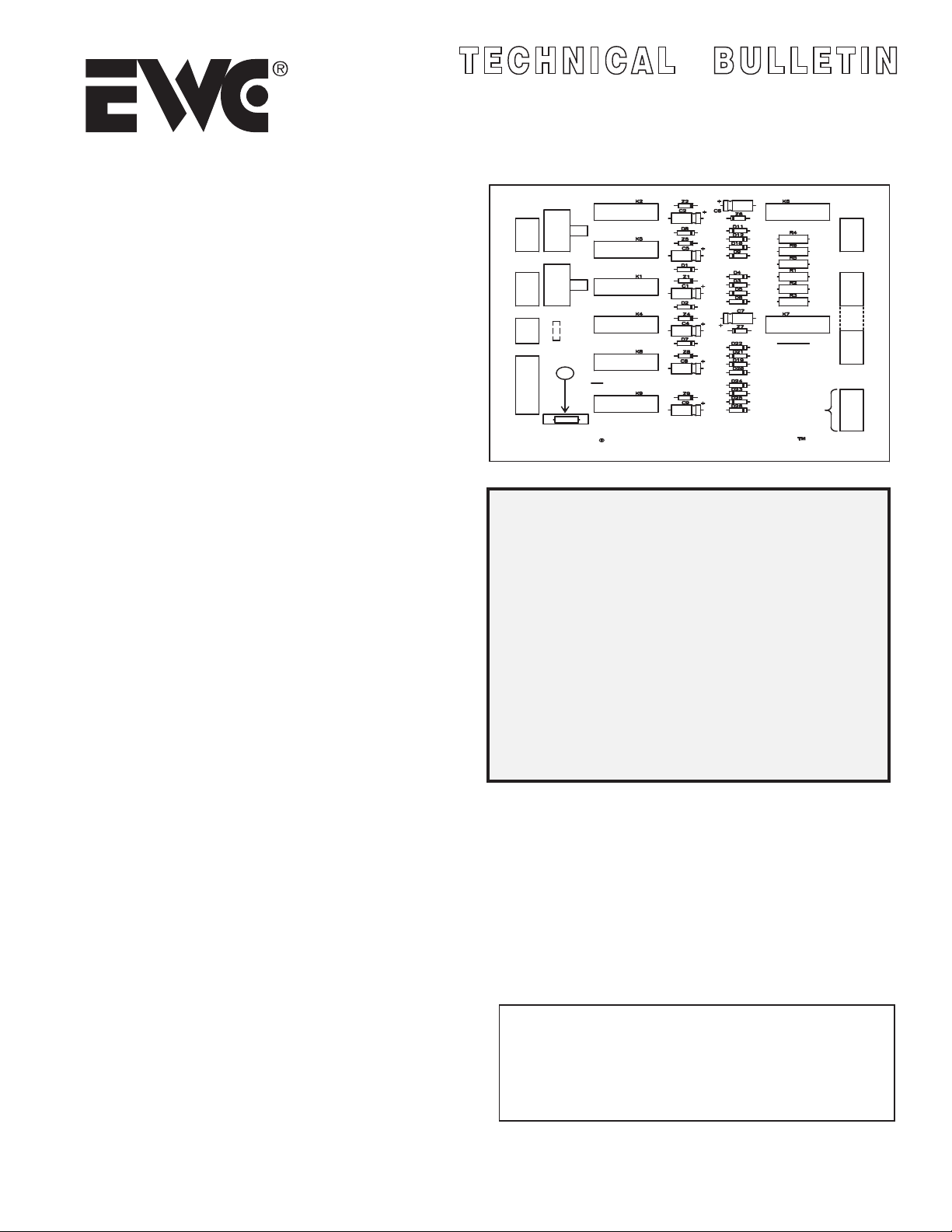
The location of the J1 jumper on the panel has also changed, and
there is now an arrow pointing to it. The J1 jumper enables
fan operation in Heat mode as well as Cooling mode.
With the exception of the Polyfuse and the J1 jumper, all
other changes have no direct bearing on the wiring,
i n s t a l l a t i o n , o r o p e r a t i o n of t h e co n t r o l pa n e l .
ZONE2
MOTOR
M6
M4
M2
M1
ZONE1
MOTOR
M6
M4
M2
M1
24VAC
T’FORMER
2
1
SYSTEM
B
O
X
Y
W
G
R
PAGE
1
2
5
SW2
OPEN
CLOSE
SW1
OPEN
CLOSE
CB1
J1
EWC
Model EWC-ST-2E
CONTROLS INC.
Englishtown, NJ
CAUTION
PLEASE read all
instructions carefully
before starting the
installation
procedures.
ADDITIONAL
ZONE PANEL
ULTRA-ZONE
CONTROL SYSTEM
EWC-ST-2E
TABLE OF CONTENTS
Introduction & Specifications
Application Notes
Typical 5 zone control panel diagram
ZONE2
T’STAT
ZONE1
T’STAT
C
W
Y
R
C
W
Y
R
R1
O
B
G
O
R
C
+
_
The ST series zone control panels are the most versatile
and rugged relay based logic control systems in use today.
The Master/Slave circuitry of these panels can be utilized
to satisfy numerous control applications and job specifications.
The heating/cooling c hangeover o peration is s till controlled b y a
changeover subbase on the zone 1 thermostat, or a separate
remote selector switch can be used instead. This allows
for inexpensive standard 2 or 3 wire thermostats to be used in all
z o n e s d e p e n d i n g o n t h e f i e l d a p p l i c a t i o n .
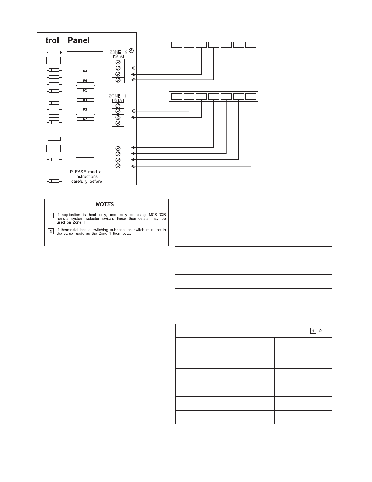
The table on Page 6 shows the types of digital programmable
thermostats t hat a re c ompatible w ith t he S T2E o r ST3E p anels.
The diagrams included with this bulletin are based upon the
most frequently asked questions regarding the wiring of these
panels. There are additional diagrams available through the
Te ch n i ca l S u p p o r t H o t l i n e @ 1 - 8 0 0 - 5 2 6 - 4 0 4 8 .
Contact the Hotline if you find yourself on the job site and
unsure of the exact wiring for your ST Series Control Panel.
TB 115 Rev. F Copyright © EWC Controls 1999-2009 All Rights Reserved.
P/N: 090375A0115
EWC Controls Inc. • 385 Highway 33 • Englishtown, NJ 07726 • 800-446-3110 • FAX
6
Thermostat Requirements
7
Checkout Procedures
8
EWC-ST-3E Wiring Diagram
SPECIFICATIONS
Power Requirements:
Wiring Connections:
24V 60Hz 40VA
Screw Terminal blocks
for Thermostat gauge wire connections.
Mounting:
Mounts with 4 screws and
mollies (included).
Panel Dimensions:
Width:
9 7/8" (251mm); Depth: 1 9/16” (40mm).
Length: 10” (254mm);
WARNING: THESE PANELS ARE DESIGNED
FOR USE WITH 24 VOLTS. DO NOT USE
ANY OTHER VOLTAGE! USE CAUTION TO
AVOID ELECTRIC SHOCK OR
EQUIPMENT
DAMAGE
732-446-5362
Page 2
OPERATION
WIRING
1. HEAT MODE:
To operate the system in the heat mode,
the "B" terminal has to be made to the "R1"
terminal on the zone 1 terminal block. This
allows any zone thermostat to call for heat.
When a zone calls for heat, the control
panel closes the circuit from "R" to "W"
activating the furnace. The zone damper
calling for heat remains open and zones
satisfied will close. The fan and limit control
in the furnace will operate the fan.
2. COOL MODE:
To operate the system in the cool mode,
the "O" terminal has to be made to the "R1"
terminal on the zone 1 terminal block. This
allows for any thermostat to call for cooling.
On call for cooling, terminals "R", "G" and
"Y" are made to bring on the fan and
compressor. The dampers for zones calling
will remain open; the dampers satisfied will
close.
3. OFF POSITION:
When the subbase on zone 1 is in the
"OFF" position the entire system is disabled.
4. CONTINUOUS FAN:
When placing the fan switch on the
subbase from "AUTO" to "ON" position, the
panel closes the circuit between "R" and "G"
terminals to energize the fan relay.
5. OPEN-CLOSE SWITCHES:
If left in the open position when all zones
satisfy, the damper will drive to open
position. If left in closed position, when all
zones satisfy , the damper will remain
closed unless it is the last zone to satisfy;
then it will remain open.
NOTE: The last zone to satisfy will always
be open regardless of position of switch.
1. HVAC SYSTEM:
Wiring the HVAC system to the EWC-ST-2E
or EWC-ST-3E is typical of wiring a subbase
to a heating/cooling system. (4 wires
required.)
The following terminals are on the system
terminal block:
R-
Wire to the RH heating transformer
and/or the RC cooling transformer.
Y-
Wire to the Compressor Relay.
W-
Wire to Heat Control (gas valve, oil
burner relay) on system terminal block.
G-
Wire to Fan Relay.
2. TRANSFORMER 24V 40VA:
A separate 24V 40VA transformer is required
to be wired to terminals 1 and 2 of the
terminal block labeled "T-Former". (2 wires
required.) This transformer powers the panel
board, thermostats and damper motors. It
does not power the furnace or the air
conditioner. The board is now protected by
a Thermal Polyfuse at the transformer input.
When the polyfuse trips it will get quite hot. To
reset the breaker, remove the 24 VAC for
approximately 30 seconds. Check the damper
motors and field wiring for shorts. If adding two
panels together, be sure of wiring in (+ and - )
circuit.
3. ZONE DAMPER MOTORS:
Use 3 conductor wire from each set of MAN
or RDN zone damper terminals or 2
conductor wire on "SR" dampers to the
panel. See diagrams #4 and 5 when wiring
more than one damper per zone.
4. THERMOSTATS:
ZONE 1: Thermostats that have subbases
with "B" and "O" terminals are required to
enable system changeover. These include
mechanical and battery operated
thermostats (6 wires required - terminals W,
Y, G, R, B and O), and electro-mechanical
and programmable digital thermostats (24
VAC, 7 wires required - terminals C, W, Y,
G, R, B and O).
If model MCS-DXB remote selector switch is
used, it will be wired to the zone 1 terminal
block in place of the changeover subbase
(7 wires required total: 4 on the MCS-DXB B, G, O and R1; 3 on the thermostat - W,
Y and R). See diagram #3.
OTHER ZONES: 3 wires are required for
mechanical and battery operated
thermostats - terminals W, Y and R. 4 wires
are required for electro-mechanical and 24
VAC digital thermostats - terminals C, W, Y
and R. No subbases required.
See page 6 for specific types of
thermostats required.
5. HEAT ONLY OR COOL ONLY
APPLICATIONS:
Zone 1 no longer requires a subbase or
remote switch. All zones need only a two
or three wire thermostat to operate in either
heat or cool.
AP PL ICA TIO N NO TES
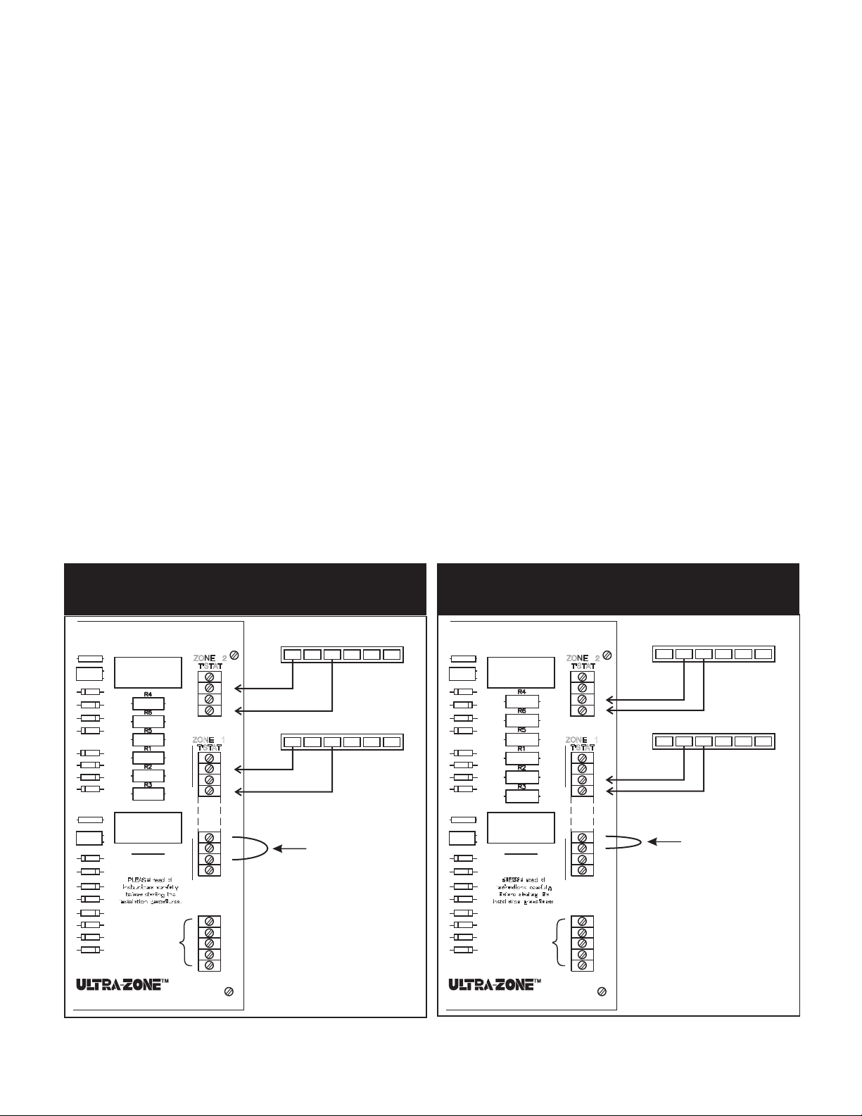
#1: WIRING DIAGRAM
HEATING ONLY INSTALLATION
rol Panel
R6
C6
+
D11
D12
D10
D9
D3
D4
D6
D5
R7
C7
+
D21
D22
CAUTION
D20
D19
D24
D23
D25
D26
ADDITIONAL
ZONE PANEL
K6
K7
ZONE 2
T'STAT
ZONE 1
T'STAT
C
W
Y
R
C
W
Y
R
R1
0
B
G
0
R
C
+
-
ZONE 2 THERMOSTAT
R
B
O
ZONE 1 THERMOSTAT
R
B
O
FIELD
INSTALLED
JUMPER
GYW
GYW
#2: WIRING DIAGRAM
COOLING ONLY INSTALLATION
rol Panel
R6
C6
+
D11
D12
D10
D9
D3
D4
D6
D5
R7
C7
+
D21
D22
CAUTION
D20
D19
D24
D23
D25
D26
ADDITIONAL
ZONE PANEL
K6
K7
ZONE 2
T'STAT
ZONE 1
T'STAT
C
W
Y
R
C
W
Y
R
R1
0
B
G
0
R
C
+
-
ZONE 2 THERMOSTAT
R
B
O
ZONE 1 THERMOSTAT
R
B
O
FIELD
INSTALLED
JUMPER
GYW
GYW
CONTROL SYSTEM
2
CONTROL SYSTEM
EWC Controls Inc. • 385 Highway 33 • Englishtown, NJ 07726 • 800-446-3110•FAX 732-446-5362
Page 3
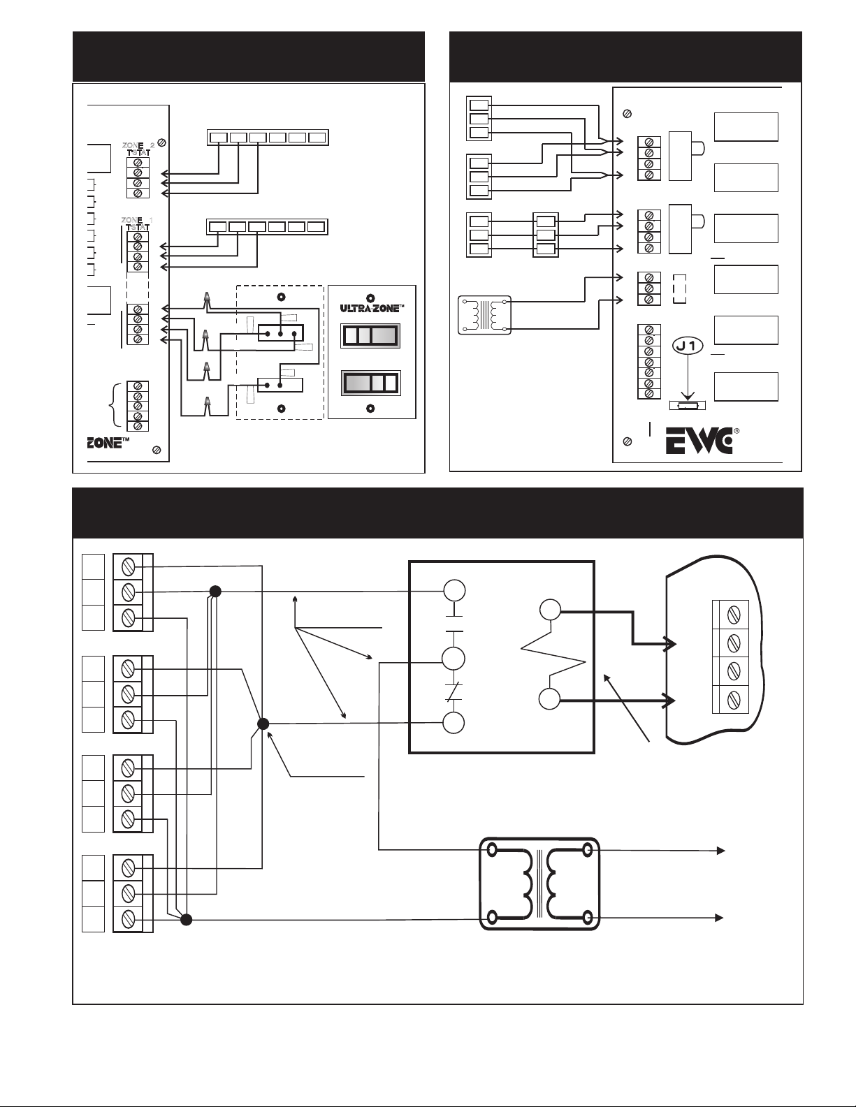
#3: EWC-ST-2E WITH MCS-DXB
REMOTE SELECTOR SWITCH
#4: TYPICAL TANDEM
DAMPER WIRING
Panel
K6
K7
CAUTION
PLEASE read all
instructions carefully
before starting the
installation procedures.
ADDITIONAL
ZONE PANEL
CONTROL SYSTEM
ZONE 2
T'STAT
ZONE 1
T'STAT
6
ZONE 2 THERMOSTAT
R
C
W
Y
R
ZONE 1 THERMOSTAT
RED
RED
BROWN
ORANGE
GREEN
R
Back of Plate
BROWN
GREEN
C
W
Y
R
R1
0
B
G
0
R
C
+
-
GYW
B
O
GYW
B
O
Front of Plate
RED
ORANGE
RED
HEAT
ON
COOL
OFF
FAN
AUTO
4
1
6
4
1
6
4
1
MA-ND4 TYPE MOTORS ON
ND OR URD TYPE DAMPERS
24VAC TRANSFORMER
40 - 60VA RATING
MAX. NUMBER OF 4 DAMPERS
PER ZONE.
6
4
1
M6
M4
M2
M1
M6
M4
M2
M1
T'FORMER
2
1
B
O
X
Y
W
G
R
ZONE2
MOTOR
ZONE1
MOTOR
24V
SW2
OPEN
CLOSE
SW1
OPEN
CLOSE
CB1
Model
K5
K2
K1
K4
K8
K9
CONTROLS
Englishtown
#5: CONTROL OF UP TO FOUR DAMPERS PER ZONE
USING EXTERNAL RELAY
6
NO
4
1
TYPICAL FEEDER CONDUCTOR
3
ZONE
MOTOR
M6
M4
C
NC
1
M2
M1
2
COIL
6
4
1
24 vac
6
TYPICAL JUNCTION POINT
4
1
6
R1 Isolation Relay
SPDT action with 24 vac coil
Relay is shown de-energized.
All dampers are closed.
H
L1
4
C
L2
One relay coil=One motor.
Don’t overload your power
transformer, by connecting
too many relays.
To Line Voltage
Provide over current
protection
1
Separate 24 vac
Transformer
Multiple Damper Wiring on a Single Zone, using a Separate Transformer
and an Isolating Relay. Maximum of 4 dampers per 40 va transformer.
EWC Controls Inc. • 385 Highway 33 • Englishtown, NJ 07726 • 800-446-3110 • FAX 732-446-5362
3
Page 4
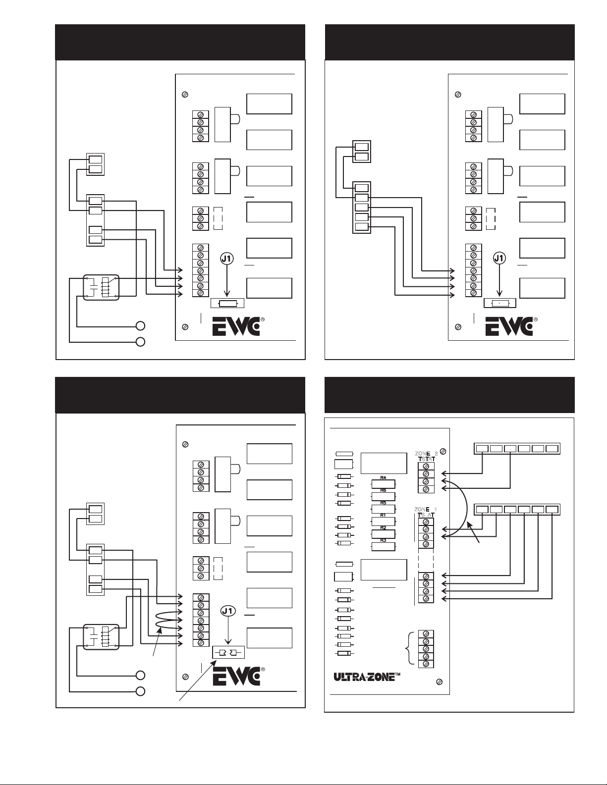
#6: TYPICAL FAN CENTER AND OIL
BURNER WITH ISOLATION RELAY
#7: TYPICAL GAS FURNACE
OUTDOOR
CONDENSING
UNIT
Y
Y
C
C
FAN
CENTER
C
Y
G
R
ISOLATION RE
HEATING
LAY
RELAY
Model
K5
SW2
ZONE2
MOTOR
M6
M4
M2
M1
ZONE1
MOTOR
M6
M4
M2
M1
24V
T'FORMER
2
1
B
O
X
Y
W
G
R
T
OPEN
CLOSE
SW1
OPEN
CLOSE
K2
K1
K4
OUTDOOR
CONDENSING
UNIT
Y
C
GAS
FURNACE
C
Y
W
CB1
K8
K9
CONTROLS
Englishtown
G
R
M6
M4
M2
M1
M6
M4
M2
M1
T'FORMER
2
1
B
O
X
Y
W
G
R
ZONE2
MOTOR
ZONE1
MOTOR
24V
SW2
OPEN
CLOSE
SW1
OPEN
CLOSE
CB1
Model
K5
K2
K1
K4
K8
K9
CONTROLS
Englishtown
T
#8: FAN CONTROL
WITH HOT WATER COIL
**CUT ‘J1’ JUMPER**
OUTDOOR
CONDENSING
UNIT
YCY
C
AIR
HANDLER
C
Y
G
R
ISOLATION
RELAY
JUMPERS
T
HEATING
RELAY
T
CUT
ZONE2
MOTOR
M6
M4
M2
M1
ZONE1
MOTOR
M6
M4
M2
M1
24V
T'FORMER
2
1
B
O
X
Y
W
G
R
#9: ZONING IN HEATING ONLY
NO ZONE CONTROLLED COOLING
Model
K5
SW2
OPEN
CLOSE
SW1
OPEN
CLOSE
CB1
K2
K1
K4
K8
K9
CONTROLS
Englishtown
rol Panel
R6
C6
+
D11
D12
D10
D9
D3
D4
D6
D5
R7
C7
+
D21
D22
CAUTION
D20
PLEASE read all
instructions carefully
D19
before starting the
installation procedures.
D24
D23
D25
D26
ADDITIONAL
ZONE PANEL
K6
K7
ZONE 2
T'STAT
ZONE 1
T'STAT
C
W
Y
R
C
W
Y
R
R1
0
B
G
0
R
C
+
-
CONTROL SYSTEM
ZONE 2 THERMOSTAT
ZONE 1 THERMOSTAT
FIELD
INSTALLED
JUMPER
R
R
GYW
B
O
GYW
B
O
4
EWC Controls Inc. • 385 Highway 33 • Englishtown, NJ 07726 • 800-446-3110 • FAX 732-446-5362
Page 5

#10: WIRING DIAGRAM
INTERCONNECTION OF TWO PANELS FOR ADDITIONAL ZONES
TRANSFORMER
DAMPER MOTORS
6
4
1
6
4
1
6
4
1
HVAC
EQUIPMENT
Y
W
G
R
C
C
Y
ZONE3
MOTOR
M6
M4
M2
M1
ZONE2
MOTOR
M6
M4
M2
M1
ZONE1
MOTOR
M6
M4
M2
M1
24V
T'FORMER
2
1
B
O
X
Y
W
G
R
MASTER PANEL
Model EWC-ST-3E
OPEN
CLOSE
SW2
OPEN
CLOSE
SW1
OPEN
CLOSE
CB1
K3
K5
K2
K1
K4
K8
K9
CONTROLS INC.
Englishtown, NJ
Z3
C3
D14
D13
Z5
C5
D7
Z2
C2
D8
Z1
C1
D2
D1
Z4
C4
Z8
C8
Z9
C9
SLAVE PANEL
D15
D16
D18
D17
Z6
C6
D11
D12
D10
D9
D3
D4
D6
D5
Z7
C7
D21
D22
D20
D19
D24
D23
D25
D26
K6
K7
CAUTION
PLEASE read all
instructions
carefully before
starting the
installation
procedures.
ADDITIONAL
ZONE PANEL
CONTROL SYSTEM
ZONE-3
T'STAT
ZONE-2
T'STAT
ZONE-1
T'STAT
ZONE 3 THERMOSTAT
R
C
W
Y
R
GYW
B
O
ZONE 2 THERMOSTAT
C
W
Y
R
R
GYW
B
O
ZONE 1 THERMOSTAT
C
W
Y
R
R
GYW
B
O
PANELS MAY BE
DAMAGED IF NOT
R1
O
B
G
O
R
C
+
-
WIRED EXACTLY
AS SHOWN
0 to 0
R to R
C to C
+ to +
- to -
DAMPER MOTORS
6
4
1
6
4
1
ZONE2
MOTOR
M6
M4
M2
M1
ZONE1
MOTOR
M6
M4
M2
M1
24V
T'FORMER
2
1
B
O
X
Y
W
G
R
Model EWC-ST-2E
SW2
OPEN
CLOSE
SW1
OPEN
CLOSE
CB1
K5
K2
K1
K4
K8
K9
CONTROLS INC.
Englishtown, NJ
Z6
Z5
C6
C5
D11
D7
D12
Z2
D10
C2
D9
D8
D3
Z1
D4
C1
D6
D5
D2
D1
Z7
Z4
C7
C4
D21
Z8
D22
C8
D20
D19
D24
Z9
D23
D25
C9
D26
CONTROL SYSTEM
K6
K7
CAUTION
PLEASE read all
instructions
carefully before
starting the
installation
procedures.
ADDITIONAL
ZONE PANEL
ZONE-2
T'STAT
ZONE-1
T'STAT
C
W
Y
R
C
W
Y
R
R1
O
B
G
O
R
C
+
-
ZONE 5 THERMOSTAT
R
B
O
ZONE 4 THERMOSTAT
R
B
O
GYW
GYW
PANELS MAY BE
DAMAGED IF NOT
WIRED EXACTLY
AS SHOWN
EWC Controls Inc. • 385 Highway 33 • Englishtown, NJ 07726 • 800-446-3110 • FAX 732-446-5362
5
Page 6
C7
R6
C6
D11
D12
D10
D4
D6
R7
D21
D22
D20
D19
TH ERMO STAT REQUIR EMENTS
ZONE 2 THERMOSTAT – MODEL EWT-3611
RH/B
RH/B
GYW
GYW
K6
+
D9
D3
D5
K7
+
CAUTION
ZONE 2
T'STAT
ZONE 1
T'STAT
C
W
Y
R
C
W
Y
R
R1
0
B
G
C
ZONE 1 THERMOSTAT – MODEL EWT-3611
C
RC/O
R
RC/O
R
ZONE 1
6 WIRES REQUIRED
DIGITAL
PROGRAMMABLE
THERMOSTATS
(Battery Operated)
EWT - 3707
1F80-261
TH4110D
SUPPLIER
EWC
CONTROLS
WHITE
RODGERS
ROBERT-
®
SHAW
HONEYWELL
DIGITAL NON-
PROGRAMMABLE
THERMOSTATS
(Battery Operated)
®
®
EWT - 3611
1F78-144
9500
®
TH3110D
ZONES 2 & HIGHER
3 WIRES REQUIRED
DIGITAL
PROGRAMMABLE
THERMOSTATS
(Battery Operated)
EWT - 3707
1F97-1271
1F80-261
TH4110D
SUPPLIER
EWC
CONTROLS
WHITE
RODGERS
ROBERT-
®
SHAW
HONEYWELL
DIGITAL NON-
PROGRAMMABLE
THERMOSTATS
(Battery Operated)
®
®
®
EWT - 3611
1F86-244
1F78-144
TH3110D
9400
9500
9610
9610
9600
6
EWC Controls Inc. • 385 Highway 33 • Englishtown, NJ 07726 • 800-446-3110 • FAX 732-446-5362
Page 7
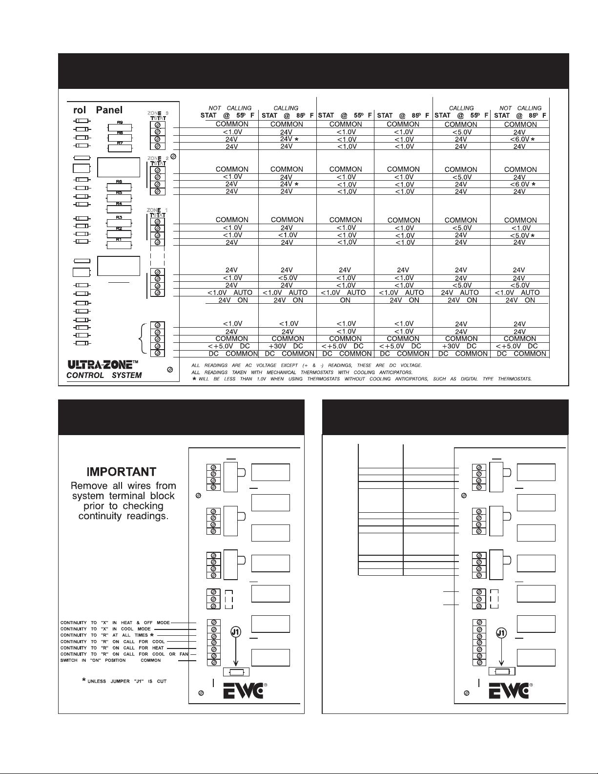
CH ECK OU T PROCEDUR E
#11: THERMOSTAT CIRCUIT
D15
D16
D18
D17
R6
C6
+
D11
D12
D10
D9
D3
D4
D6
D5
R7
C7
+
D21
D22
D20
D19
D24
D23
D25
D26
K6
K7
CAUTION
PLEASE read all
instructions carefully
before starting the
installation
procedures.
ADDITIONAL
ZONE PANEL
ZONE 3
T'STAT
ZONE 2
T'STAT
ZONE 1
T'STAT
HEATING MODE
C
W
Y
R
C
W
Y
R
C
W
Y
R
R1
0
B
G
0
R
C
+
-
OFF MODE
COOLING MODE
#12: SYSTEM CIRCUIT
ZONE3
MOTOR
M6
M4
M2
M1
ZONE2
MOTOR
M6
M4
M2
M1
ZONE1
MOTOR
M6
M4
M2
M1
24V
T'FORMER
2
1
B
O
X
Y
W
G
R
EWC-ST-3E
OPEN
CLOSE
SW2
OPEN
CLOSE
SW1
OPEN
CLOSE
CB1
K3
K5
K2
K1
K4
K8
K9
CONTROLS
Englishtown
#13: DAMPER CIRCUIT
STAT
DAMPER
OPEN
O VOLTS
24 VOLTS
24 VOLTS
COMMON COMMON
O VOLTS
24 VOLTS
24 VOLTS 24 VOLTS
COMMON
O VOLTS
24 VOLTS
24 VOLTS
COMMON
INPUT TO PANEL:
NOTE: Conditions shown are with at
least one thermostat always calling.
When all thermostats satisfy, damper
position will depend on position of
"OPEN-CLOSED" switch. In "OPEN"
position, damper will drive to open
position. In "CLOSED" position, all
voltage is removed from damper motor;
motor will remain in whatever position it
was in when all thermostats satisfied.
If 24 volts is present from M1 to M4 and
M1 to M6, damper motor may either be
turning or stuck between open and
closed postions.
CALLING
NOT CALLING
CLOSED
24 VOLTS
O VOLTS
24 VOLTS
24 VOLTS
O VOLTS
COMMON
24 VOLTS
O VOLTS
24 VOLTS
COMMON
24 VOLTS
COMMON
ZONE3
MOTOR
M6
M4
M2
M1
ZONE2
MOTOR
M6
M4
M2
M1
ZONE1
MOTOR
M6
M4
M2
M1
24V
T'FORMER
2
1
B
O
X
Y
W
G
R
OPEN
CLOSE
SW2
OPEN
CLOSE
SW1
OPEN
CLOSE
CB1
EWC-ST-3E
K3
K5
K2
K1
K4
K8
K9
CONTROLS
Englishtown
EWC Controls Inc. • 385 Highway 33 • Englishtown, NJ 07726 • 800-446-3110 • FAX 732-446-5362
7
Page 8
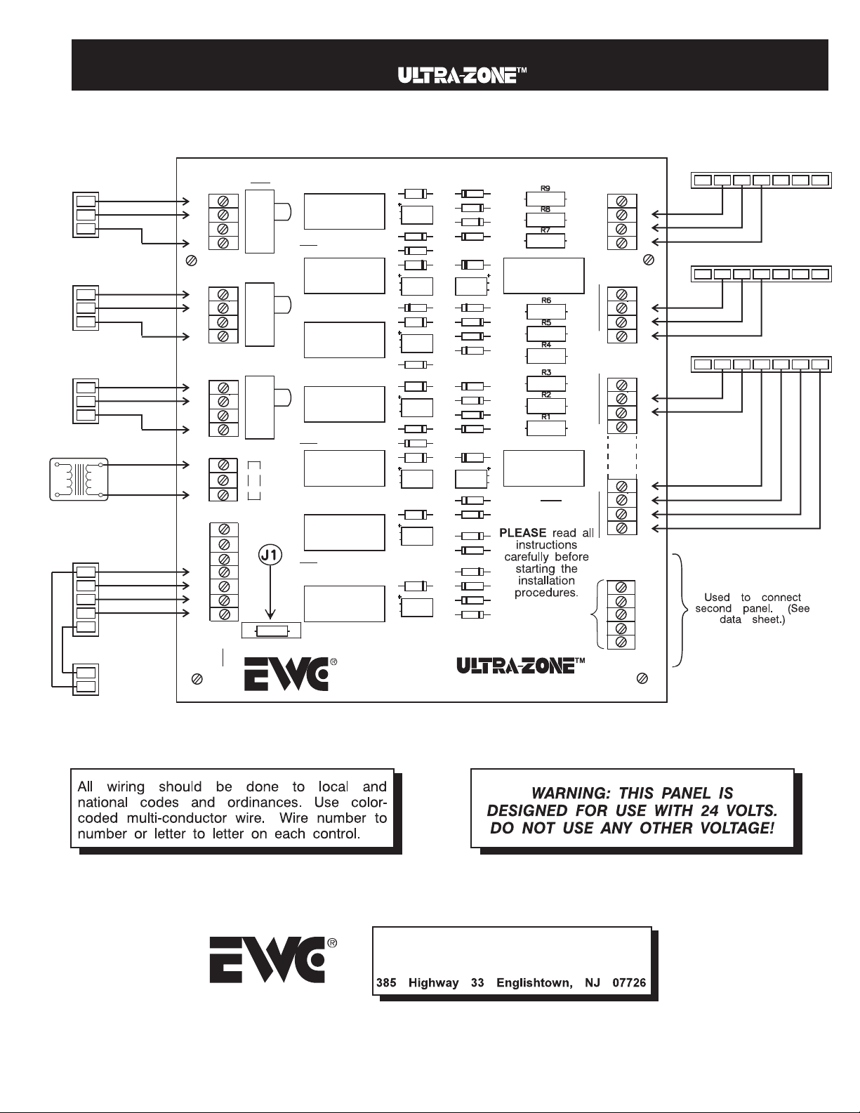
#14: WIRING DIAGRAM
MODEL EWC-ST-3E CONTROL PANEL
DAMPER MOTORS
6
4
1
6
4
1
6
4
1
24VAC
TRANSFORMER
HVAC
EQUIPMENT
Y
W
G
R
C
C
Y
ZONE3
MOTOR
M6
M4
M2
M1
ZONE2
MOTOR
M6
M4
M2
M1
ZONE1
MOTOR
M6
M4
M2
M1
24V
T'FORMER
2
1
B
O
X
Y
W
G
R
SW2
SW1
CB1
OPEN
CLOSE
OPEN
CLOSE
OPEN
CLOSE
Model EWC-ST-3E
K3
K5
K2
K1
K4
K8
K9
CONTROLS INC.
Englishtown, NJ
Z3
C3
D14
D13
Z5
C5
D7
Z2
C2
D8
Z1
C1
D2
D1
Z4
C4
Z8
C8
Z9
C9
D15
D16
D18
D17
D11
D12
D10
D21
D22
D20
D19
D24
D23
D25
D26
CONTROL SYSTEM
ZONE 3 THERMOSTAT – MODEL EWT-3611
ZONE-3
T'STAT
YW
C
RC/O
R
RH/B
G
C
W
Y
ZONE-2
T'STAT
R
ZONE 2 THERMOSTAT – MODEL EWT-3611
YW
C
RC/O
R
RH/B
G
Z6
C6
K6
C
W
Y
ZONE-1
T'STAT
R
ZONE 3 THERMOSTAT – MODEL EWT-3611
YW
C
RC/O
R
RH/B
G
C
W
Y
R
D9
D3
D4
D6
D5
Z7
C7
K7
R1
O
CAUTION
B
G
O
ADDITIONAL
ZONE PANEL
R
C
+
-
Excellence Without Compromise
Technical . . . . . . . 800-446-3110
Sales . . . . . . . . 800-446-3110
Fax . . . . . . . . .
732-446-5362
CONTROLS INC.
8
EWC Controls Inc. • 385 Highway 33 • Englishtown, NJ 07726 • 800-446-3110 • FAX 732-446-5362
 Loading...