

Page 1
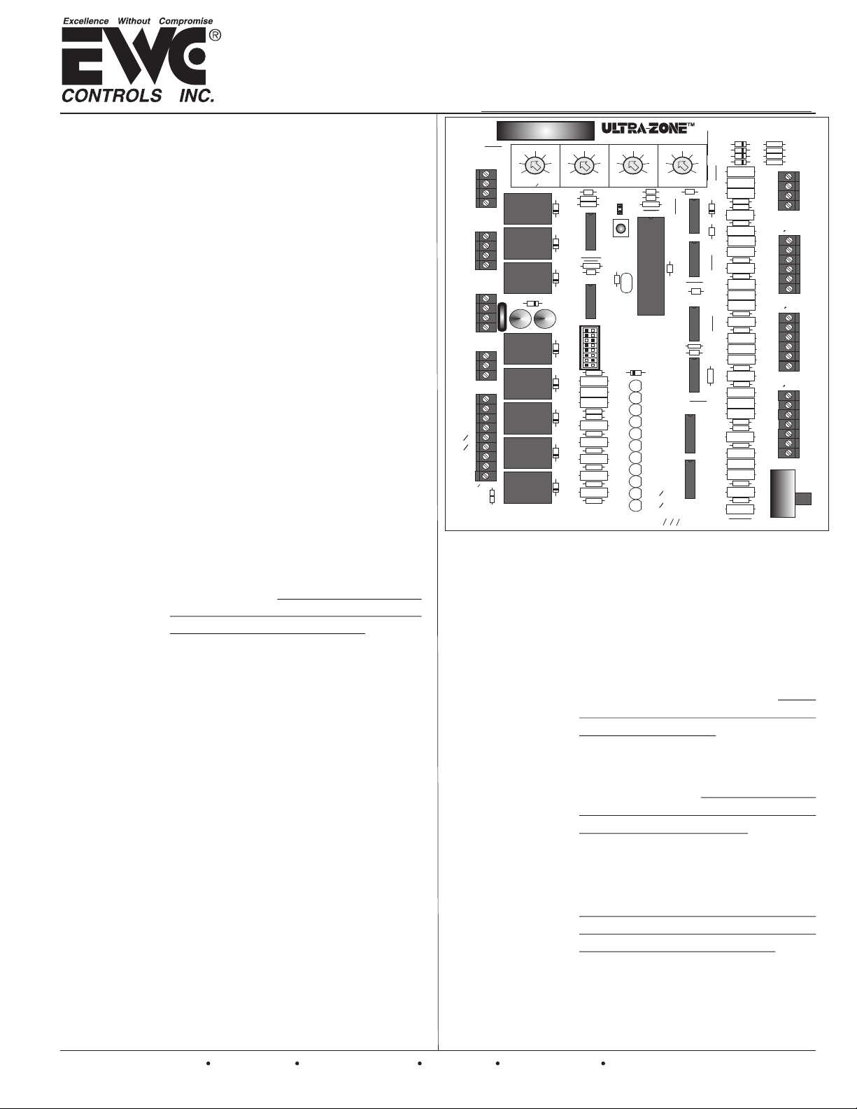
The BMPlus Zone Control System allows you to easily
upgrade an inefficient single zone HVAC system, into a
Multi-zone, Energy savings, Comfort producing, HVAC
system. The Superior Design, Intuitive Firmware, Simple
Setup Options, Easy to Understand wiring and Backwards
Compatibility, makes the BMPlus Zoning system the
Contractors dream. Combined with EWC Motorized
Dampers and any off-the-shelf Thermostats, EWC Controls
sets another high standard in the residential & light
commercial Forced Air Zoning Industry.
Zone
Capacity
The main module controls three zones
using motorized dampers and may be
expanded to 5 or 7 zones, using 1 or 2
Model XM2 Expansion Modules.
Compatible
HVAC
Systems
Controls 2 & 3 stage conventional or dual
fuel heat pumps, without the need for dual
fuel kits. Also single or two-stage gas, oil,
& hydronic heating systems, with single or
two stage air conditioning. Constant or
variable speed fan systems.
Compatible
Thermostats
Compatible with any off the shelf
H e a t P u m p T h e r m o s t a t
(2heat/1cool). You may also use any
reg ular H eat /Coo l the r mos tat
(1heat/1cool). You may still use
regular Heat/Cool thermostats to
control a Heat Pump system.
Automatic
Heat/Cool
Changeover
The BMPlus Zone system features
aut omat ic chan geo ver f rom any
thermostat allowing for individual zone
comfort from the HVAC system.
Status LED
The STATUS LED pulses as a steady
heart beat to indicate active Microprocessor status.
System LEDs
On board LED’s illuminate to indicate
HVAC system mode, system status,
active and inactive zone identification.
See page 10 for details.
Damper LEDs
LEDs labeled Zone 1 thru Zone 7 indicate
which dampers are energized open.
Operating
Power
Operating
Conditions
TB-228
P/N 090375A0228 REV. H 06.01.10
EWC Controls Inc. 385 Highway 33 Englishtown, NJ 07726 800-446-3110 FAX 732-446-5362 E-Mail- [email protected]
INPUT VOLTAGE: 19-30VAC 60 Hz
Transformer 40-100VA MAX. NEC Class 2.
CURRENT DRAW: Max 15VA @ 24VAC.
OVER-CURRENT PROTECTION: 4.0 amp
TEMPERATURE: -20° to 160°F (-29° to 71°C)
HUMIDITY: 0% - 95% RH Non-Condensing.
Copyright © 2007 EWC Controls All Rights Reserved
TECHNICAL BULLETIN
Models BMPlus 3000/5000/7000 Rev. B
Leave this bulletin on the job site for future reference!
J
1
21
VAC
14
7
OFF
STAGING
TIMER
R
1
4
D
F1
+
1
C
M6
M4
M2
M1
M6
M4
M2
M1
M6
M4
M2
M1
T’FORMER
R
ZONE3
MOTOR
ZONE2
MOTOR
ZONE1
MOTOR
24
C
SYSTEM
G
Y2
Y1
O
B
W1
W2
E
RH
RC
C
RH
RC
LINK
CONTROLS INC.
Englishtown, NJ
W
E
C
Figure 1
Box Contents
Thermal
Circuit
Breaker
Indoor Fan
Control
28
35
42
OAS
K
1
D
K
2
D
K
3
D
+
2
C
K
D
5
K
D
6
K
7
D
K
D
8
K
D
9
CONTROL
43
40
46
37
34
2
R
1
2
3
4
5
R
R
R
6
R
R
7
R
R
8
R
120
49
110
52
LIMIT
5
C
R
15
R
16
U
1
RESET
R
13
12
C
U
9
C
3
SW
HP
DF
HC
O
OAS
OFF
OFF
GAS
R
19
20
21
22
R
23
R
24
25
R
26
27
R
28
29
R
30
31
R
32
33
34
R
130
R
3
13
SYSTEM
<
HP
<
TSTATS
<
<
<
<
<
< >
LED
LED
LED
LED
LED
LED
LED
LED
LED
LED
LED
140
HIGH
LIMIT
R
1
Y
>
RV
STAGING
50
%
SAS
FAN
1
2
3
4
5
6
7
8
9
10
11
TEMPLOW TEMP
7
C
8
C
14
>
CONV
>
B
>
RULE
ON
>
HYDRONIC
SYSTEM
150
160
12
170
OTHER
HP
TIMER
>
ON
>
Z
1
STATUS
OAS
SAS
ZONE
ZONE
ZONE
FAN
Y
2
Y
1
1
W
W
2
19
5
ND STAGE HEAT
2
DIFFERENTIAL
R
4
2
U
11
C
3
2
1
B
EM
10
D
26
11
D
33
12
D
13
D
40
47
15
C
3
U
21
D
10
C
4
U
C
14
5
U
R
66
C
9
6
U
R
35
7
U
8
U
R
70
73
R
R
72
R
77
R
76
BMPlus3000 rev B
* BMPlus 3000 Control Panel
* Supply Air Sensor
* Technical Bulletin TB228
* Mounting Hardware
The BMPlus module has a Thermal
circuit breaker that protects the
module(s) from shorts in the damper
and thermostat field wiring. It will
not protect against shorts in the
HVAC system wiring.
CAUTION: When the circuit breaker
is tripped it will get quite hot. To
reset the breaker: Shut off power to
the panel. Find and repair the short.
Restore the 24VAC power.
Any zone can activate the indoor fan
and only the dampers in zones calling
for continuous fan operation will open.
Continuous fan operation will only
occur when there are no active or
pending, heat or cool demands.
switch is provided to enable automatic
fan operation in heat mode. Useful for
straight electric heat or hydronic heat
applications.
R
36
37
R
R
38
R
39
R
41
SAS
R
42
SAS
R
43
R
40
R
82
R
44
48
R
R
50
R
79
54
R
58
R
R
60
R
71
R
64
68
R
OAS
OAS
R
81
ZONE3
R
45
T
STAT
46
R
C
R
47
W/E
O/B
R
49
Y
R
R
51
G
52
R
ZONE2
R
53
T
STAT
C
R
78
W/E
R
55
O/B
Y
R
56
R
57
R
G
R
59
ZONE1
T
STAT
R
61
C
62
R
W/E
R
63
O/B
Y
R
65
R
G
ONE
R
67
ZONE
R
69
EM
NORM
4
SW
A dip
1
Page 2
BMPlus 3000 FIRMWARE/HARDWARE FEATURES
*Built-In
Timer
Settings
*Startup
Delay
Timer
*Short Cycle
Timer
*Changeover
Timer
*Opposing
Call
Delay Timer
Staging
Timer / OAS
21
14
7
OFF
STAGING
Timer / OAS
28
35
42
OFF, 7 to 42
minutes or 7
to 42
degrees F.
Any setting
below 7 is off!
DO NOT set to off
if using OAS
*Supply Air
Limit
Delay Timer
*Purge Delay
Timer
2
EWC Controls Inc. 385 Highway 33 Englishtown, NJ 07726 800-446-3110 FAX 732-446-5362 E-Mail- [email protected]
The panel has seven built-in Delay Timers
Cooling and Heating Limit Controls
that insure safe & reliable operation.
* Start-up Delay Timer = 3 minutes-fixed
* Short Cycle Timer = 3 minutes-fixed
* Change Over Timer = 4 minutes-fixed
* Opposing Call Timer = 20minutes-fixed
* Staging Timer = OFF or 7-42 min. -Adj.
* Supply Air Limit Timer = 3minutes-fixed
* Purge Delay Timer = 90 seconds-fixed
The panel will not activate any
cooling or heating operations until
the startup delay has expired. This
occurs after any initial power up,
after any power failure or after
40
37
34
LOW TEMP
LIMIT
130
120
110
HIGH TEMP
LIMIT
43
140
46
49
52
150
160
170
The Adjus t able C o oling L imit
potentiometer sets the supply air
temperature at which the cooling is
cycled off and the fan continues to run,
allowing the coil to warm up.
The A d j ustab l e H e a ting L i mit
potentiometer sets the 1st stage heat
supply air temperature, at which the
heating is cycled off and the fan
continues to run, allowing the heat
exchanger or coil to cool down.
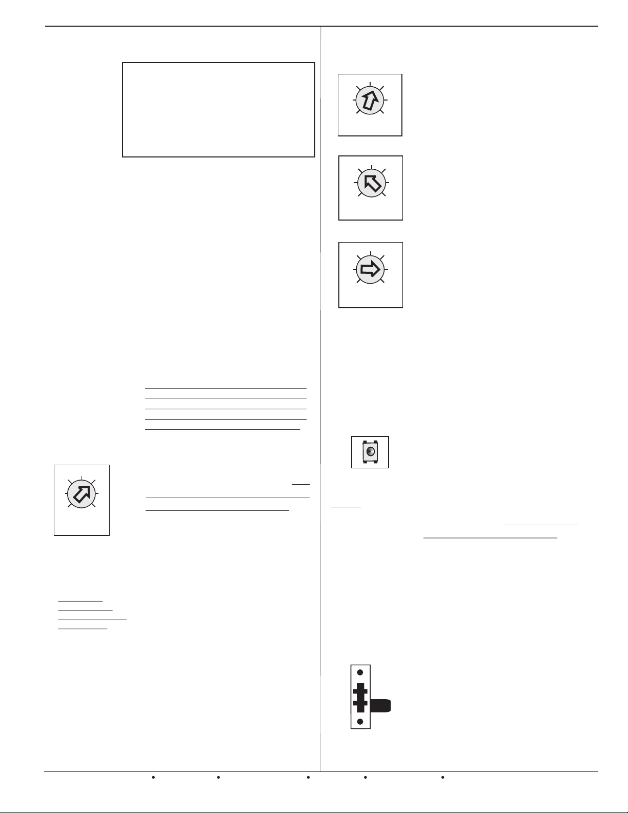
pressing the Reset button for 7
Wh en all zone demands are
satisfied, the panel will not resume
the same mode of operation for a
minimum of 3 minutes.
A built-in timer prevents the system
from rapidly switching between
heating and cooling modes. At the
end of a call, a 4 minute timer is
started and the panel will not switch to
Example:
Hi Temp. Limit =130°F
plus 2nd stg. DT= 40°F
New Limit = 170°F.
26
19
12
5
2nd STAGE HEAT
DIFFERENTIAL
33
40
47
the opposing mode until the timer has
expired.
A 20 minute delay must expire, or the
active zone(s) must satisfy, before
the panel will honor a thermostat
de mand to changeover to th e
opposite mode of system operation.
Reset
BUTTON
The STAGING TIMER sets the
amount of continuous call time in 1st
stage, before second stage heat or
cool is energized. NOTE: The
potentiometer also serves as the
Outside Air Changeover Setting.
The BMPlus 3000 can inhibit heat
staging based on a Timer or
O u t s i d e A i r Te m p e r a t u r e .
NOTE: An Optional OAS Sensor is
RESET
Always reset the CPU
anytime you make
dip-switch changes to
the BMP3000 panel!
DO NOT use a sharp
object to press the
button! Your finger tip
will work fine.
required to use the OAS feature.
NOTE: 2nd stage cool delay defaults
The Adjustable 2nd st age heat
differential potentiometer sets the 2nd
stage heat supply air temperature, at
which the heating is cycled off and the
fan continues to run, allowing the heat
exchanger or coil to cool down.
NOTE: Allows the supply air sensor to
be installed in the supply air plenum,
regardless of the coil/heat exchanger
configuration. Allows the installer to fine
tune virtually any multi stage heating
system!
The separate reset buttons on the
old BMP3000 have been replaced
by a single button with dual
functions. Momentarily pressing the
RESET button clears the built-in timers
controlling the Startup delay timer,
Short cycle timer, W2 timer, Supply air
sensor timer and the Changeover
timer. This enables you to test the
installation faster. Caution should be
observed when using this button.
Pressing the RESET button for 7
seconds will reset the CPU for
the entire zone system.
to 30 minutes, if OAS is chosen to
inhibit 2nd stage Heat.
The time delay of 3 minutes must
expire before the BMPlus 3000 will
re-energize heat or cool mode. This
delay occurs when the processor
detects the supply air temperature is
higher or lower than the High or Low
temperature limit settings.
The last Damper(s) will be held Open
for 90 seconds at the end of every call
Emergency
Heat
Switch
EM
NORM
An On-Board Switch is provided that
allows the Customer to set the system
to the Emergency heat mode.
This switch is shown in the NORMAL
position.
This switch would be used for Heat
Pump applicati ons where t he
Customer chooses to use Regular
Heat/Cool thermostats instead of
Heat Pump thermostats.
allowing a system purge into the last
zone that was calling.
Page 3
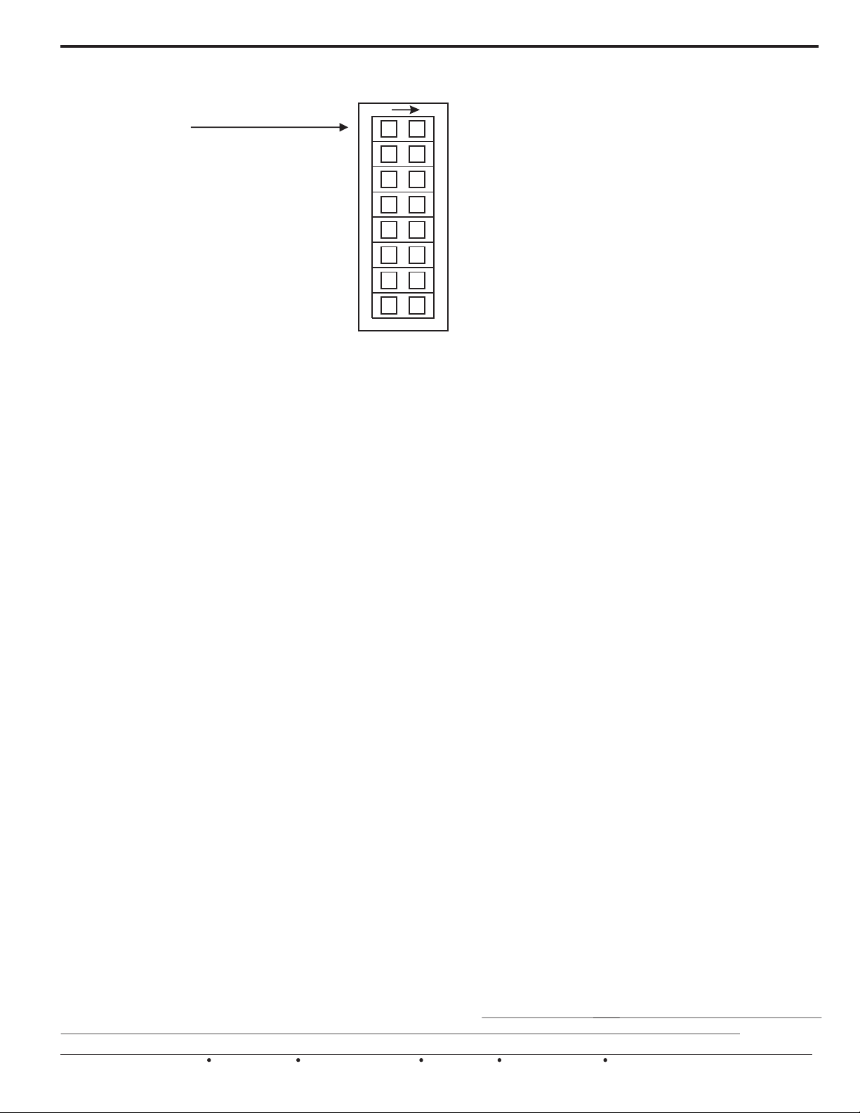
Selecting the Options Using the DIP Switches
***FS = Factory Settings
RECORD YOUR OWN DIP SWITCH
SETTINGS HERE
Program m i n g a nd setting up the B M P l us
3000 to control your HVAC system is very easy!
Look below for an explanation of each dip
switch function and choose your settings .
Some functions may not apply to your application.
Then use a pencil to mark/record your settings. If the
se t t i n g s g e t c h a n g e d l a t e r on , y o u w i l l
have a record of the original settings.
HP < SYSTEM > OTHER
Choose the type of HVAC system you want to control. Select HP, if your system is any type of Heat Pump. Select OTHER,
if your system is a standard Gas or Oil furnace. Other setting also applies to straight electric furnaces or hydronic
(hot water coil) heating systems.
DF < HP > CONV
Choose the type of Heat Pump you want to control. Select DF (Restricted Mode) if you wish to lock out the
compressor during auxiliary heat operation, typically set for Dual Fuel operation. Select CONV (Unrestricted Mode) if
you wish to have the compressor run during auxiliary heat operations, typically set for Electric Back-up.
ONON
1
1
HP < SYSTEM > OTHER FS
2
2
DF < HP > CONV FS
3
3
FS HC < TSTATS > HP
4
4
FS O < RV > B
5
5
OAS < STAGING > TIMER FS
6
6
FS OFF < 50%RULE > ON
7
7
FS OFF < SAS > ON
8
8
FS GAS < FAN > HYDRONIC
HC < TSTATS > HP
Select HC, if you want to use regular Heat/Cool thermostats on your job. Select HP, if you want to use Heat Pump
thermostats on your job. Remember that you can use standard Heat/Cool Thermostats on a Heat Pump application.
IMPORTANT NOTE: The BMPlus 3000 Zone Control System allows Heat Pump thermostats to be connected to all zones.
Using heat pump thermostats means that the zone panel will obey thermostatic demands. This comfort over-ride feature
provides a level of versatility to your zoning system and gives the homeowner comfort control over the system, instead of
waiting for the adjustable timer to energize 2nd stage heat. True thermostatic staging is not available when using 2 Stage
compressor heatpumps, it is advisable to use Heat/Cool thermostats and allow the BMPlus to stage via the on-board timer. If
true thermostatic staging is required, then it is recommended to upgrade to the Model UZC series of Control Panels.
O < RV > B
Select the correct Reversing Valve signal for your particular Heat Pump. Choose “O” for any Heat Pump that energizes
the RV in the cooling mode. Choose “B” for any Heat Pump that energizes the RV in heating mode.
OAS < STAGING > TIMER
Select OAS, if you want to delay auxiliary heat based on the outside air temperature sensor. Select TIMER, if you
want to delay staging heat & cool based on the adjustable on-board timer. NOTE: ‘Y2’ defaults to a 30
minute delay, when OAS is chosen. NOTE: An optional Outside Air Sensor (OAS) is required to use the OAS feature.
OFF < 50%RULE > ON
Select OFF, if you do not want to inhibit auxiliary heat/cool based on the total number of zones calling. Select ON, if you
want to inhibit auxiliary heat/cool based on the total number of zones calling. More than half the total zones must be
calling for the same mode, or auxiliary will not activate. If or has been selected, the 50% rule will apply to
cooling operations only, auxiliary heat will not be affected. The 50% rule will always dominate the staging timer or
thermostat demands unless Emergency mode is active.
DF OAS
OFF < SAS > ON
Select OFF, if you do not want to use the supply air sensor included with the BMPlus Zone Control system. Select ON, if
you intend to use the included supply air sensor. Refer to the data sheet included with the supply air sensor for details.
GAS < FAN > HYDRONIC
Select GAS, if your HVAC system is a gas or oil forced air furnace. Select HYDRONIC, if your HVAC system has a hot
water coil, or straight electric heat with no indoor blower support. Useful when you need the indoor blower to run
automatically in heat mode, just like it does in cool mode. NOTE: When you select HP on dip switch #1, the indoor fan
mode is automatically set for you. There is no need to move this switch when setting up for Heat Pump operations.
EWC Controls Inc. 385 Highway 33 Englishtown, NJ 07726 800-446-3110 FAX 732-446-5362 E-Mail- [email protected]
3
Page 4
INSTALLATION & WIRING INSTRUCTIONS
WARNING: THESE PANELS ARE DESIGNED FOR USE WITH 24VAC. DO NOT USE OTHER VOLTAGES! USE CAUTION TO AVOID ELECTRIC
SHOCK OR EQUIPMENT DAMAGE. ALL WORK SHOULD BE PERFORMED TO LOCAL AND NATIONAL CODES AND ORDINANCES. USE 18
AWG SOLID COPPER, COLOR-CODED, MULTI-CONDUCTOR THERMOSTAT CABLE.
Mount the panel housing in a suitable/convenient location. Avoid locations that may become wet or
produce condensation. Hot attics are OK. Use the knockouts on the panel housing as wire entryways. Strain relief fittings can be used
if desired. Use care and do not damage the circuit board when removing the knockouts and making wire connections. NOTE: The
24vac power supply should be supplied by a separate transformer. DO NOT use the 24vac power supply from the HVAC system
unless there is no other alternative. 2 zones and 2 dampers is the limit when stealing voltage from the HVAC system.
Mounting hardware is provided.
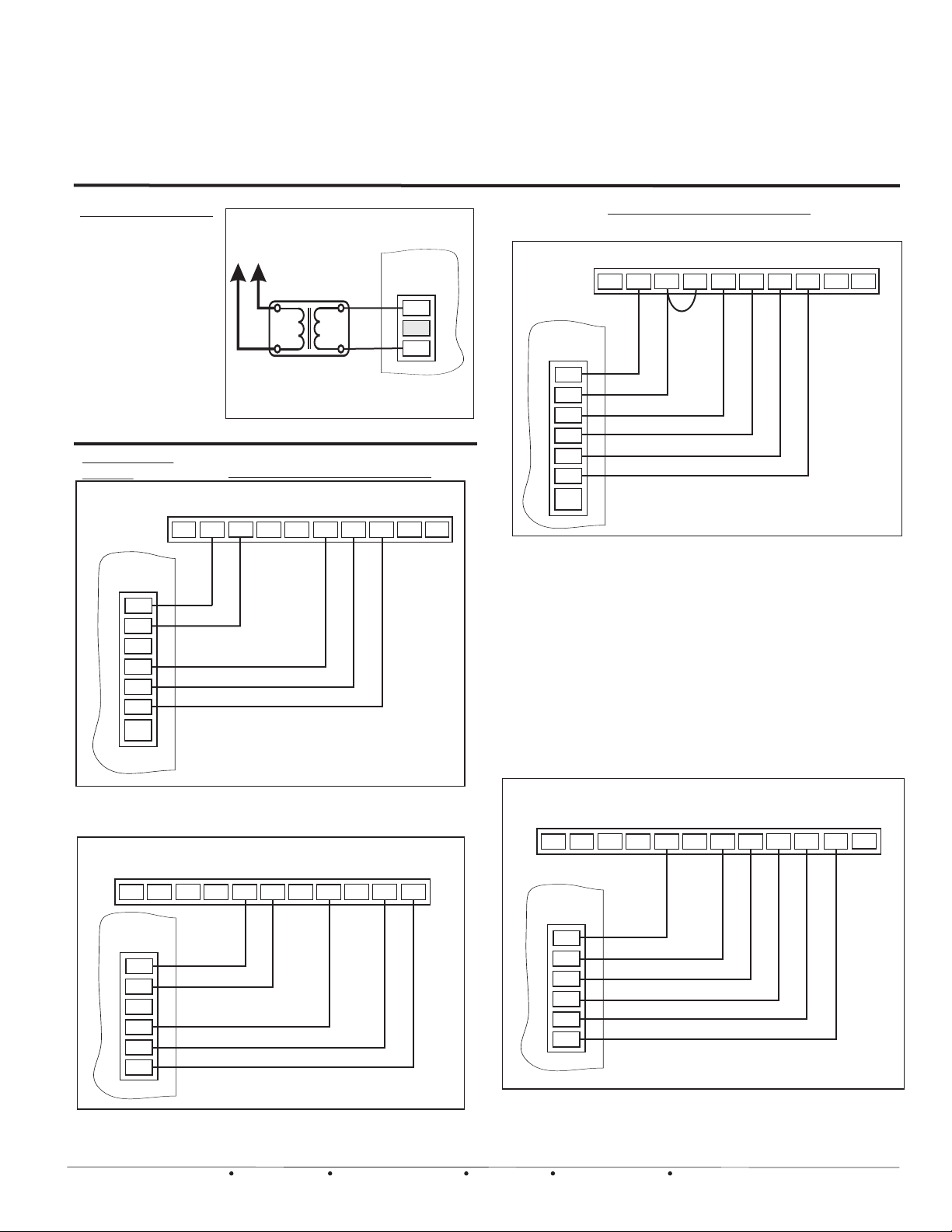
POWER WIRING
A single 24vac, 40va
UL Listed transformer
c a n p o w e r t h e
BMPl u s 300 0 M ain
module with up to 12
genuine ND or URD
dampers. See page 9
for more load and
transformer data.
Thermostat
Wiring
B
C
ZONE1
T’STAT
C
W/E
O/B
Y
R
G
ONE
ZONE
*
Common wire not required if batteries are used.
*
BMPlus 3000
Line
Voltage
24vac, 40 - 75va Max
PROVIDE
MEANS OF
DISCONNECT
TRANSFORMER
UL LISTED
Main Module
24 VAC
T’FORMER
R
C
R - Hot
C - Common
Figure 2 BMPlus 3000 Power wiring
HEAT/COOL THERMOSTATS
MODEL EWT-3707
MODEL EWT-3707
R
W1
E
G
Y1
O
W2
L
HEAT PUMP THERMOSTATS
MODEL EWT-3707
MODEL EWT-3707
R
B
W1
C
G
Y1
O
E
W2
L
*
ZONE1
T’STAT
C
W/E
O/B
Y
R
G
ONE
ZONE
*
*
Figure 2c.
NOTE: The BMPlus 3000 allows the user to install Heat
Pump thermostats on all zones. You may still use regular
Heat/Cool type thermostats with a Heat Pump system and
use the Staging Timer to energize the auxiliary heat. Doing
so may save more energy. It is advisable to use Heat/Cool
thermostats with 2 stage compressor Heat Pumps.
Model EWT-3707: Configured for 2 heat 1 cool
heat pump (HP1 mode). See thermostat for
further details.
**
Common wire not required if batteries are used.
Field installed jumper.
*
Figure 2a.
Figure 2b.
4
Model EWT-3707: Configured for 1 heat 1 cool
(SS1 mode). See thermostat instructions for
Further details.
TOUCHSCREEN THERMOSTAT
MODEL EWT-3102
L
S1
ZONE2
T’STAT
C
W/E
O/B
Y
R
G
S2
Y2
C
*
Common wire not required if batteries are used.
*
Model EWC-3102: Configured for 1 heat 1 cool
(SS1 mode). Can be configured for heat pump.
W1
E
Y1
W2
R
G
Figure 2d.
TOUCHSCREEN THERMOSTAT
MODEL EWT-3102
S1
S2
L
Y2
C
W2
E
O/B
Y1
R
*
ZONE2
T’STAT
C
W/E
O/B
Y
R
G
Common wire not required if batteries are used.
*
Model EWC-3102: configured for 2 heat 1 cool
heat pump (HP1 mode). See thermostat instructions
for further details.
See thermostat instructions for further details.
EWC Controls Inc. 385 Highway 33 Englishtown, NJ 07726 800-446-3110 FAX 732-446-5362 E-Mail- [email protected]
G
Page 5
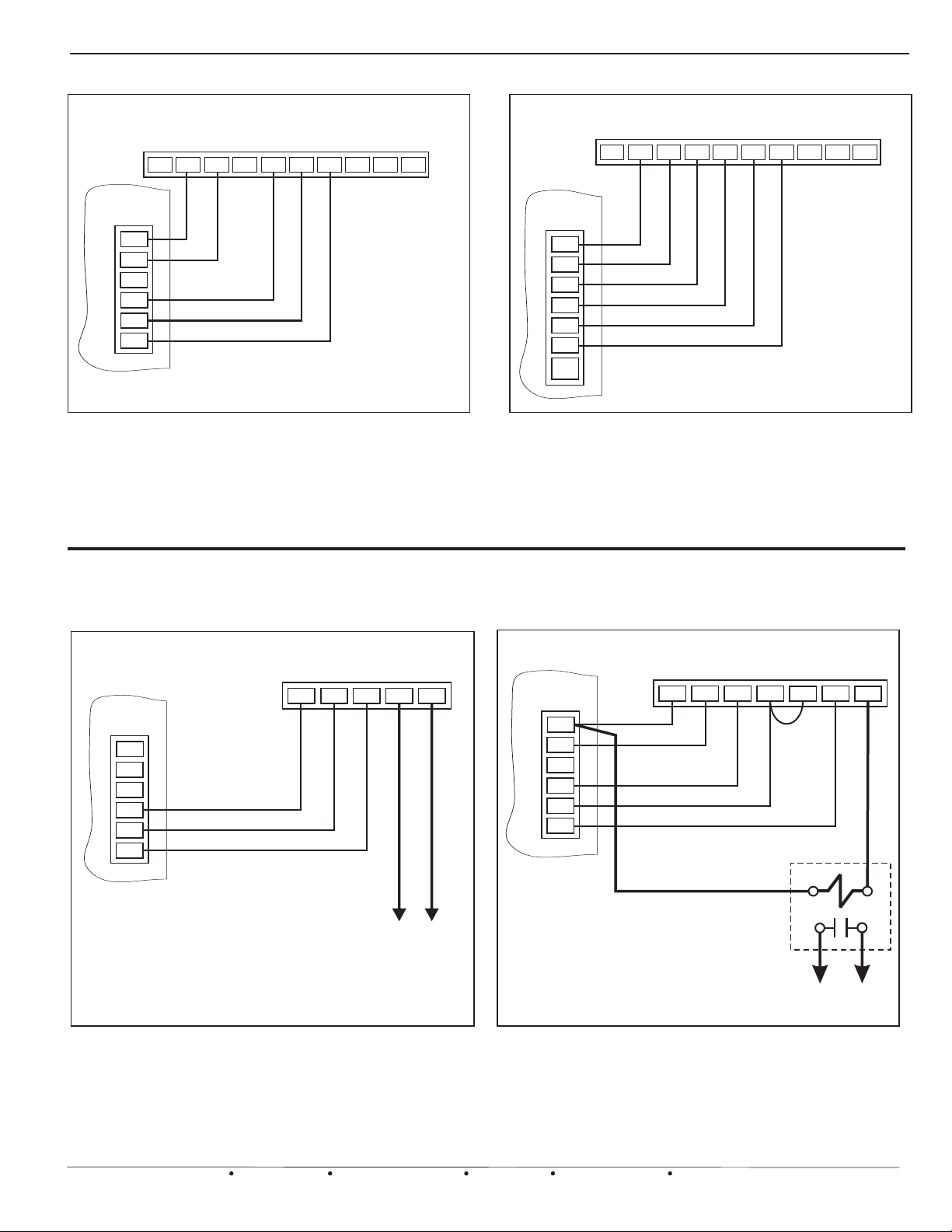
THERMOSTAT WIRING CONTINUED
WIRELESS THERMOSTAT: RECIEVER MODULE
MODEL EWT-3900
Figure 3
G
R
ZONE2
T’STAT
C
W/E
O/B
Y
R
G
C
L
W1
Y1
O
Model EWT-3900: Wireless Thermostat.
Configured for 1 heat 1 cool (SS1 mode).
Can be configured for heat pump. See
thermostat instructions for further details.
W2
E
WIRELESS THERMOSTAT: RECIEVER MODULE
MODEL EWT-3900
W1
O
Y1
R
E
G
W2
B
C
B
ZONE1
T’STAT
C
W/E
O/B
Y
R
G
ONE
ZONE
Figure 4
L
Model EWT-3900: Wireless Thermostat.
Configured for 2 heat 1 cool heat pump
(HP1 mode.)See thermostat instructions for
further details.
ZONE2
T’STAT
C
W/E
O/B
Y
R
G
Thermostat should be battery powered.
*
WIRING FOR RADIANT FLOOR HEAT
HEAT/COOL
THERMOSTAT
GRC
Y
To Radiant floor / Baseboard heat
zone valve or pump relay
RH
MULTISTAGE HEAT/COOL
*
W
ZONE2
T’STAT
C
W/E
O/B
Y
R
G
C
THERMOSTAT
W2
To Radiant floor / Baseboard heat
zone valve or pump relay
RCY
G
RH
SPST 24vac
Isolation Relay
W1
Figure 5
Wiring a split circuit thermostat to operate a
Radiant floor heating or Baseboard heating
Hydronic system. The BMPlus 3000 controls the
cooling only in this type of configuration.
EWC Controls Inc. 385 Highway 33 Englishtown, NJ 07726 800-446-3110 FAX 732-446-5362 E-Mail- [email protected]
Figure 6
Wiring for a Radiant floor loop as the first
stage of heat via the isolation relay and 2nd
stage Forced Air heat is controlled through the
zone panel.
5
Page 6
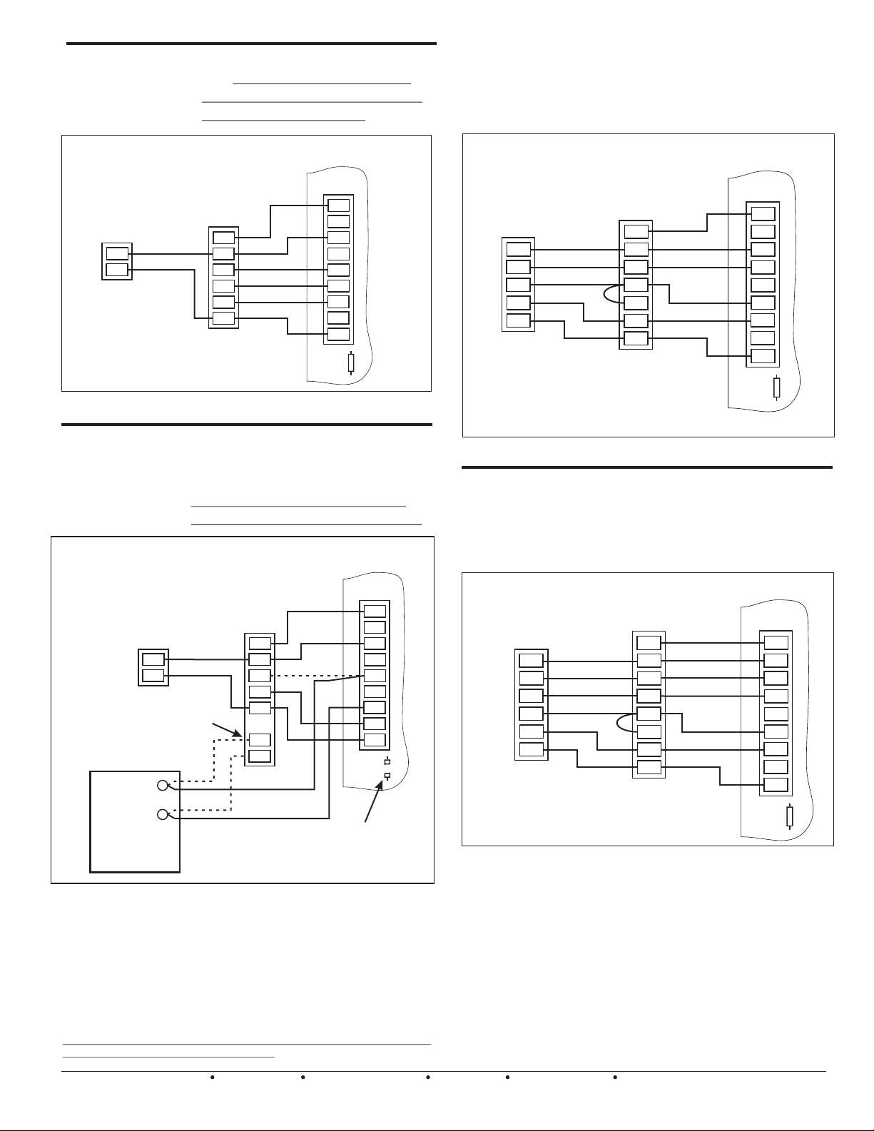
SYSTEM WIRING
Single
Transformer
Gas or Electric
Furnace & A/C
1 or 2 Stage Heat
Typical gas or Electric Furnace with
A/C. Note the common “C” wire is
connected to the SYSTEM terminal
block of the BMPlus 3000.
Conventional or Dual Fuel 2 Heat / 1 Cool Heatpump
with O (Cool) Type Reversing Valve
Typical heat pump system wiring with electric resistance or
Gas backup heat (No Dual Fuel kit required). This diagram
applies to air cooled or geothermal / ground source
systems.
BMPlus 3000
SYSTEM
G
Y2
Y1
O
W1/B
W2/E
RH
RC
C
RC/RH
LINK
OUTDOOR
CONDENSING
UNIT
Y
C
To make troubleshooting
easier, connect the “C”
Common from the Furnace
to the BMPlus. If you don’t
connect it, it’s OK.
GAS or Electric
Furnace
1or2 STAGE
G
Y
W1
W2
R
C
Figure 7 Single transformer Conventional system.
Two
Transformer
Systems
Wiring diagram for a typical oil burner,
hydronic zone / Air handler with A/C.
Cut the Rc / Rh link on the BMPlus
Panel for systems requiring isolation.
BMPlus 3000
SYSTEM
G
Y2
Y1
O
W1/B
W2/E
RH
RC
C
RC/RH
LINK
You may need
to Cut the
RC/RH Link
OUTDOOR
CONDENSING
UNIT
Y
C
*
OIL
BURNER
PRIMARY
CONTROL
OR
Boiler Control
OR
Zone Valve Control
OR
Circulator Control
ISOLATION
TERMINALS
OR WIRES
T
T
TYPICAL FAN
CENTER
TERMINAL
BLOCK
G
Y
W
R
C
T
T
Figure 8 Two transformer Oil or Hydronic / A/C system.
* Note: Your Air Handler may include a W terminal. That means
it may have it’s own isolation circuit. If you can confirm this,
simply connect the W1/B terminal to the W terminal on the air
handler. Do not cut the Rc/ Rh jumper. Wire up your Oil Burner,
Circulator relay, or Hydronic Zone valve to the isolation
contacts or wires provided in the air handler. The fan is
controlled via the time delay relay inside the air handler.
Don’t worry if you accidentally cut the Rc/Rh link. Just install your
own jumper across the Rc/Rh terminals!
6
EWC Controls Inc. 385 Highway 33 Englishtown, NJ 07726 800-446-3110 FAX 732-446-5362 E-Mail- [email protected]
BMPlus 3000
HEAT PUMP
1 STAGE
Y
O
X/W
R
C
AIR HANDLER
OR 1 0R 2 STAGE
GAS FURNACE
G
Y
O
W1
W2
R
C
SYSTEM
G
Y2
Y1
O
W1/B
W2/E
RH
RC
C
RC/RH
LINK
Figure 9 -- 2 Heat / 1 Cool Heat Pump System
Conventional or
Dual Fuel 3 Heat /
2 Cool Heat Pump
with O (Cool) Type
Conventional or Dual Fuel Heat Pump wiring
with 3 Heat / 2 Cool. With electric or Gas
Furnace Backup (No dual fuel kit is required).
This diagram applies to air cooled or
geothermal / ground source systems.
Reversing Valve
BMPlus 3000
AIR HANDLER
HEAT PUMP
2 STAGE
Y2
Y1
O
X/W
R
C
OR 1 0R 2 STAGE
GAS FURNACE
G
Y2
Y1
O
W1
W2
R
C
SYSTEM
G
Y2
Y1
O
W1/B
W2/E
RH
RC
C
RC/RH
LINK
Figure 10 – 3 Heat / 2 Cool Heatpump System
**Note that a Conventional & Dual fuel heat pump wire up more or less the
same. The difference is how auxiliary heat operates. In a Conventional
system, the indoor fan & the compressor continues to run when auxiliary
energizes. In a Dual Fuel system, the indoor fan & the compressor shuts
down when auxiliary energizes. The BMPlus 3000 will perform these
functions automatically. All you have to do is set the dip switches to the
correct settings. Select CONV or DF at dip switch #2. Install regular
Heat/Cool thermostats and choose to activate auxiliary heat by TIMER or by
OUTSIDE AIR TEMPERATURE. (Optional Sensor required). Or you may
choose to install Heat Pump Thermostats on all zones. When the
thermostat auxiliary heat demand is satisfied, the BMPlus 3000 will stage
down, unless DF or OAS has been selected and the outdoor temperature is
lower than the OAS changeover setting. In that case the system will
continue in FUEL mode, until all current heating demands are satisfied.
Page 7
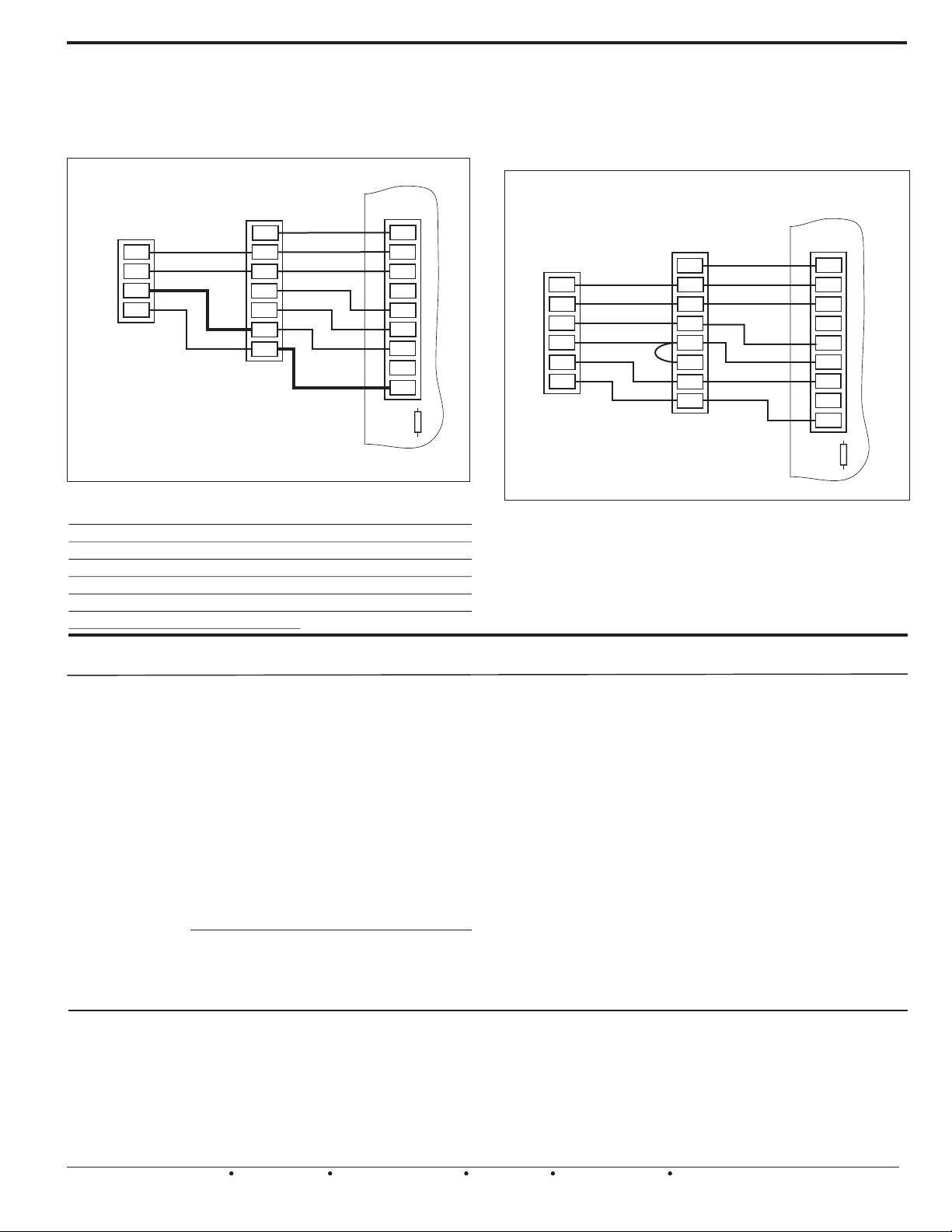
SYSTEM WIRING CONTINUED
Single
Transformer
Gas & A/C
2 stage heat
2 stage cool
Typical 2 stage gas furnace with 2
stage A/C. Constant or variable
speed systems can be connected
and controlled. Choose Timer or
Outside air to delay 2nd stage.
BMPlus 3000
2 STAGE
OUTDOOR
CONDENSING
UNIT
Y2
Y1
R
C
NOTE: If desired, you can connect a “C” Common
wire back to the “System” terminal block. Use it as
a TEST point while troubleshooting.
NOTE: The “R” wire connection to the condensing
unit may not be required on your system.
2 STAGE GAS
FURNACE
G
Y2
Y1
W1
W2
R
C
SYSTEM
G
Y2
Y1
O
W1/B
W2/E
RH
RC
C
RC/RH
LINK
Figure 11 Single transformer 2 Stage Heat & Cool system
Warning: All of the wiring diagrams provided are
general in nature and may not perfectly match your
particular application, due to differences in HVAC Mfr’s
design and terminal designations and functions!
Variations on these diagrams and other System or
Thermostat applications are available by contacting the
EWC Technical Support Hotline.
Conventional or
Dual Fuel 3 Heat /
2 Cool Heat Pump
with B (Heat) Type
Reversing Valve
HEAT PUMP
2 STAGE
Y2
Y1
B
X/W
R
C
Conventional or Dual Fuel Heat Pump wiring
with 3 Heat / 2 Cool with B (Heat) Type
Reversing Valve. Electric or Gas Furnace
Backup (No dual fuel kit is required). This
diagram applies to air cooled or geothermal /
ground source systems.
AIR HANDLER
OR 1 0R 2 STAGE
GAS FURNACE
G
Y2
Y1
B
W1
W2
R
C
Figure 12 -- 3 Heat / 2 Cool Heat Pump with
B (Heat) Type Reversing Valve
BMPlus 3000
SYSTEM
G
Y2
Y1
O
W1/B
W2/E
RH
RC
C
RC/RH
LINK
ENHANCED FEATURES AND FUNCTIONS
MODULE TO MODULE FACTORY POWER WIRING
The BMPlus 3000 includes Factory Power
Wiring on all expanded systems. The 24 vac
power to the expansion modules is fed
through the bus cable. This simplifies your
wiring and minimizes the chances of reversing
polarity.
SHORTED ZONE FEATURE FIRMWARE
The BMPlus 3000 Zone Control System
includes the Shorted Zone Feature. This
feature allows the BMPlus to ignore demands
from a zone thermostat that is putting out
simultaneous demands for heat & cool. A
condition most likely due to a short in the field
wiring, incorrect wiring, or a defective
DUAL FUEL COMPATIBLE
The BMPlus 3000 is compatible with Dual Fuel
Heat Pumps. Dual Fuel kits are not required.
Select staging based on Adjustable Time
thermostat. The BMPlus will honor any
legitimate demands from any other zone(s),
except the shorted zone. When the problem is
identified and repaired, the BMPlus 3000 will
automatically recognize that zone.
Delay or an Optional Outside Air temperature
Sensor. The intelligent firmware does the rest.
* OFF, 7 TO 42 MINUTE STAGING TIME DELAY SETTINGS
* 7 TO 42°F. OUTSIDE AIR CHANGEOVER
*SECOND STAGE 50% ZONE RULE SAVES ENERGY
* STATUS LED’s ARE INCLUDED ON ALL MODULES
* OPERATES WITH MULTI STAGE HEATPUMPS
* ADJUSTABLE DIFFERENTIAL LIMIT CONTROL
EWC Controls Inc. 385 Highway 33 Englishtown, NJ 07726 800-446-3110 FAX 732-446-5362 E-Mail- [email protected]
*1 ZONE MODE COMPLIES WITH CALIFORNIA TITLE 24
* SIMPLIFIED WIRING AND EASY SYSTEM SETUP
7
Page 8
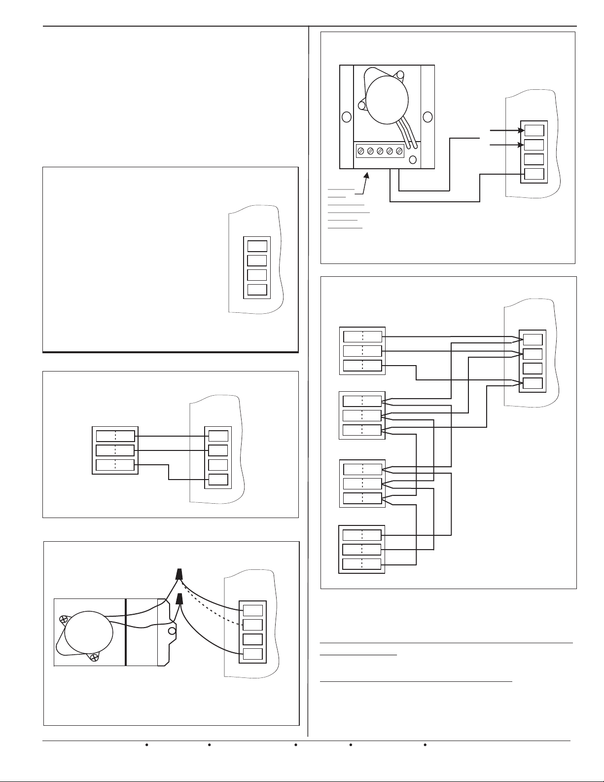
DAMPER WIRING AND CONFIGURATION
Note: All zone dampers default to the "OPEN"
position after a purge delay has occurred.
Dampers also default “OPEN” during
changeover & short cycle delays, and when
all zone demands are satisfied, and no
signals are detected from the thermostats.
REFERENCE THESE DIAGRAMS PRIOR TO
INSTALLATION AND POWER WIRING. DOING SO WILL
SAVE TIME AND LABOR LATER ON.
ZONE MODULE DAMPER
MOTOR TERMINAL BLOCK
DESIGNATION & FUNCTION
ZONE
MOTOR
Terminal M6
Terminal M4
Terminal M2
Terminal M1
Figure 13
24vac to Close a damper(s)
24vac to Open a damper(s)
Constant 24vac HOT
Common 24vac
.
M6
M4
M2
M1
All Models ND, URD and SID Damper Wiring
All Models ESR Damper Wiring
MA-ESR
Either one
Not both
NC NO C M M
Auxilary
SPDT
End Switch
Dry Contacts
Rated for
24vac only
A Spring Open Damper is wired to M1 & M6
A Spring Close Damper is wired to M1 & M4
Figure 16
.
Multiple ND and/or URD
Damper Wiring on a Single Zone
(2-4 Dampers)
6
PC
4
PO
1
COM
ZONE
MOTOR
{
M6
M4
M2
M1
ZONE
MOTOR
M6
M4
M2
M1
ZONE
MOTOR
6
PC
4
PO
1
COM
Figure 14
All Models RSD Damper Wiring
MA-RSD
M6
M4
M2
M1
ZONE
MOTOR
M6
M4
M2
M1
6
PC
4
PO
1
COM
6
PC
4
PO
1
COM
NOTE: Do not connect more
PC
PO
COM
Figure 17
6
4
1
than 4 motor actuators in a
series configuration. That will
decrease the chances of poor
electrical connections and
voltage drop issues. If wiring
more than 4 dampers see figure
18.
On all these dampers and most older style
dampers, including competitor’s dampers,
always wire up number to number or designation
to designation.
Do not overload your transformer!
Figure 15
8
A Spring Open Damper is wired to M1 & M6
A Spring Close Damper is wired to M1 & M4
Contact EWC Controls Technical Support when you
are on the job site for assistance with damper wiring.
Have a Multi-Meter, pocket screw driver and wire
snips on hand.
EWC Controls Inc. 385 Highway 33 Englishtown, NJ 07726 800-446-3110 FAX 732-446-5362 E-Mail- [email protected]
Page 9
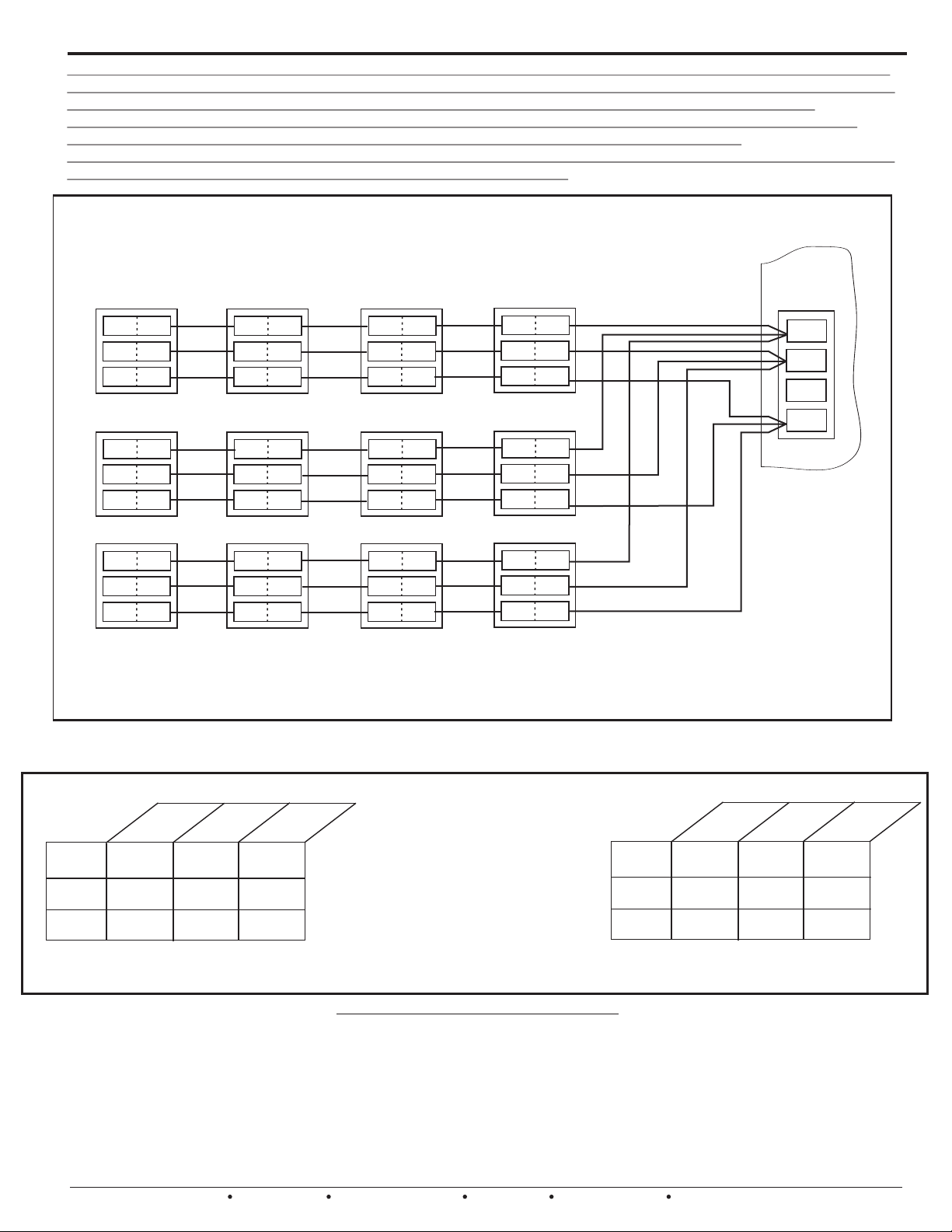
DAMPER WIRING CONTINUED
If you need to connect numerous dampers to a single zone, or you are using dampers of unknown current draw
such as Spring Types, Isolation relays and separate power supplies may be required. Parallel as many dampers
as you want as long the total current load of the motor actuators does not exceed the VA rating of the
transformer. Other factors should also be considered, such as the full load amp rating of the isolating relay
contacts, voltage drops from long wire runs and feeder conductor sizing to junction points.
NOTE: Some older style dampers and competitor’s dampers cannot be paralleled and must be isolated or wired
in tandem. Contact EWC Controls Technical Support for assistance.
Variations on this diagram and other damper solutions are available.
ZONE
MOTOR
6
PC
PO
COM
PC
PO
COM
6
4
1
6
4
1
PC
PO
COM
PC
PO
COM
6
4
1
6
4
1
PC
PO
COM
PC
PO
COM
6
4
1
6
4
1
PC
PO
COM
PC
PO
COM
M6
4
1
M4
M2
M1
6
4
1
6
PC
PO
COM
6
4
1
PC
PO
COM
6
4
1
PC
PO
COM
6
4
1
PC
PO
COM
4
1
12 Dampers wired to a single zone.
Figure 18
BMPlus 3000, 5000, 7000, Revision “B” Recommended Power Solutions
ND / URD’s
@ 2 VA
per damper
40VA
BMPlus
3000
BMPlus
5000
BMPlus
Zone Panel
7000
Non-inherently current limiting transformers must have field provided over-current protection on the secondary 24 vac output. The table values
provided pertain to genuine ULTRAZONE Dampers and Competitors typical 24vac Spring loaded dampers. Included in these VA load ratings are the
correct number of thermostats, the BMPlus Zone System, and a 5% field factor. Spring loaded dampers draw higher currents & require more power.
ND / URD / SMD / BMD Dampers - Connect 24vac common to terminal 1 and 24vac hot to terminal 4. Damper should
Open. Remove 24vac hot from terminal 4 and apply to terminal 6. Damper should Close.
RDN / SMDL / BMDL Dampers - Connect 24vac common to terminal 1 and 24vac hot to terminals 2 and 4. Damper
should Open. Remove 24vac hot from terminal 4. Damper should Close.
SR / ESR / RSD Power Close / Spring Open Dampers - Connect 24vac common & hot to the two motor (M) terminals.
Damper should Close. Remove 24 vac hot. Damper should Open.
SR / ESR / RSD Power Open / Spring Close Dampers - Connect 24vac common & hot to the two motor (M) terminals.
Damper should Open. Remove 24vac hot. Damper should Close.
12
9
5
EWC Controls Inc. 385 Highway 33 Englishtown, NJ 07726 800-446-3110 FAX 732-446-5362 E-Mail- [email protected]
Transformer Size
60VA
22
19
30
26
15 23
75VA
These charts show the maximum
number of dampers that can be
connected to the entire
BMPlus3000/5000/7000 based on the
transformer being used.
Maximum number of dampers
per ZONE is 12.
Use Class 2 UL Listed 1585 Inherently
current limiting transformers only!
Zone Panel
TES T I N G D A M P E R MOTORS
Spring Types
@ 8 VA
per damper
BMPlus
3000
BMPlus
5000
BMPlus
7000
3
2
1
40VA
Transformer Size
VA
0
6
5
4
7
6
3 5
5VA
7
9
Page 10

LED’S
BMPlus 3000
LED’s
RED
STATUS
RED
OAS
RED
SAS
RED
ZONE 3
RED
ZONE 2
The BMPlus is equipped with 11 LED’s which indicate system operation and status. Familiarize
yourself with the LED’s definitions, in order to quickly & accurately determine the current
system status and mode of operation.
The STATUS LED pulses as a steady heart beat to indicate proper Microprocessor system status.
The OAS LED illuminates solid to indicate that the Outdoor Temperature has fallen below the chosen
set point. LED will blink rapidly to indicate a malfunctioning Outdoor Air Sensor.
The SAS LED illuminates solid to indicate that the Supply Temperature has exceeded the chosen
set point on either the HIGH TEMP LIMIT or the LOW TEMP LIMIT. LED will blink rapidly
to indicate a malfunctioning Supply Air Sensor.
The ZONE 3 LED will illuminate solid to indicate that damper(s) is energized open, and the Zone is active.
The ZONE 2 LED will illuminate solid to indicate that damper(s) is energized open, and the Zone is active.
RED
RED
RED
RED
RED
RED
ZONE 1
FAN
Y2
Y1
W1/B
W2/E
The ZONE 1 LED will illuminate solid to indicate that damper(s) is energized open, and the Zone is active.
The FAN LED will illuminate solid to indicate a demand for fan operation, during COOLING, HEATING,
PURGE, or CONTINUOUS FAN.
The Y2 LED illuminates solid to indicate 2nd stage of COOLING is energized in Gas mode.
The Y2 LED illuminates solid to indicate 2nd stage of HEATING is energized in Heat Pump mode.
The Y1 LED illuminates solid to indicate 1st stage of COOLING is energized in GAS/HYDRONIC or
HEAT PUMP mode.
The Y1 LED illuminates solid to indicate 1st stage HEATING in HEAT PUMP MODE.
The W1/B LED illuminates solid to indicate 1st stage of HEATING is energized in Gas/Hydronic mode.
The W1/B LED illuminates solid to indicate ‘B’ reversing valve is energized in HEAT PUMP operation.
The W2/E LED illuminates solid to indicate 2nd or 3rd stage of HEATING is energized in GAS/HYDRONIC
or HEAT PUMP mode.
The W2/E LED illuminates solid to indicate EMERGENCY HEAT is energized in HEAT PUMP mode.
NOTES:
10
EWC Controls Inc. 385 Highway 33 Englishtown, NJ 07726 800-446-3110 FAX 732-446-5362 E-Mail- [email protected]
Page 11
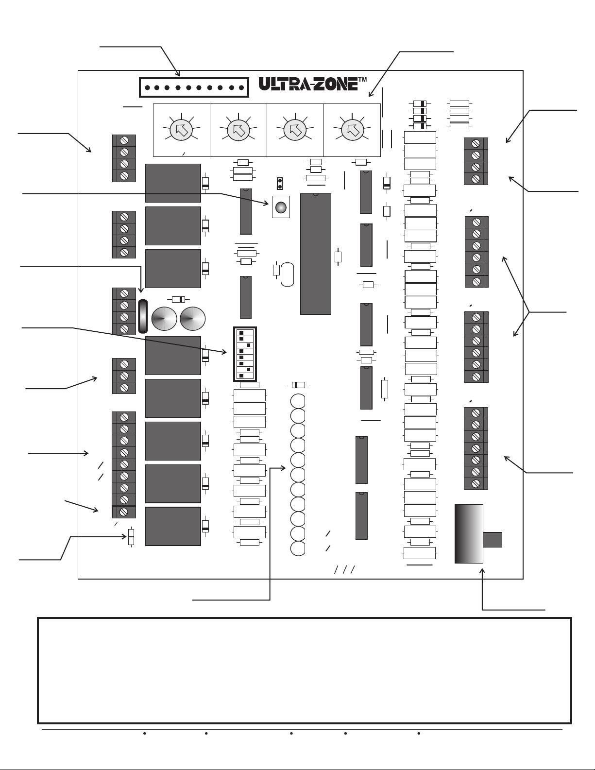
Rugged Damper
Motor Terminal
Blocks
Dual Function
Reset
Button
Thermal Circuit
Breaker
Easy Setup
8 switch Bank
Polarized
Power Input
Terminals
Isolated HVAC
System
Terminal
Block
Isolated Common
terminal. Useful
when HVAC
troubleshooting
On-Board
CUTTABLE
Rc/Rh Link
Rugged 10 pin
Expansion Header
Protective
header cap not
shown for clarity
ZONE3
MOTOR
M6
M4
M2
M1
ZONE2
MOTOR
M6
M4
M2
M1
ZONE1
MOTOR
M6
M4
M2
M1
24
T’FORMER
R
C
SYSTEM
G
Y2
Y1
O
B
W1
W2
E
RH
RC
C
RH
RC
LINK
W
E
Figure 19
J
VAC
C
1
21
14
7
OFF
STAGING
TIMER
R
F1
OAS
1
4
D
+
1
C
CONTROLS INC.
Englishtown, NJ
System Status LED’s
BMPlus3000
3 Zone Main
User Friendly
Adjustable
Potentiometers
Module
Supply Air
CONTROL
43
40
28
37
35
34
42
2
R
K
1
1
D
K
2
U
LIMIT
1
46
130
120
49
110
52
HIGH
R
3
5
C
R
15
R
16
RESET
2
D
K
3
U
9
3
D
+
2
C
3
SW
K
4
D
5
R
19
5
K
R
20
21
R
D
6
R
22
K
6
R
23
R
24
25
R
R
26
7
D
R
27
7
K
R
28
29
R
R
30
D
8
R
31
K
8
R
32
R
33
34
R
D
9
C
HP
DF
HC
O
OAS
OFF
OFF
GAS
R
13
12
13
C
SYSTEM
<
HP
<
TSTATS
<
<
<
<
<
< >
LED
LED
LED
LED
LED
LED
LED
LED
LED
LED
LED
1
Y
RV
STAGING
50
SAS
FAN
1
2
3
4
5
6
7
8
9
10
11
BMPlus3000 rev B
140
LIMIT
>
%
TEMPLOW TEMP
C
C
R
14
CONV
>
RULE
>
7
8
>
SYSTEM
150
160
170
OTHER
>
HP
B
TIMER
>
ON
>
ON
HYDRONIC
Z
1
STATUS
OAS
SAS
ZONE
ZONE
ZONE
FAN
Y
2
Y
1
1
W
W
2
19
12
5
ND STAGE HEAT
2
DIFFERENTIAL
R
4
2
U
11
C
3
2
1
B
EM
10
26
3
U
4
U
5
U
6
U
7
U
8
U
D
11
D
33
12
D
13
D
40
47
15
C
21
D
10
C
C
14
R
66
C
9
R
35
R
70
73
R
R
72
R
77
R
76
R
R
R
R
40
R
82
R
R
44
R
R
R
48
R
R
R
50
R
R
R
R
79
R
54
R
R
R
R
58
R
R
R
60
R
R
R
R
71
R
64
R
68
R
R
R
41
43
81
45
53
78
55
63
67
69
42
46
47
49
51
52
56
57
59
61
62
65
ZONE3
T
ZONE2
T
STAT
ZONE1
T
STAT
4
SW
R
36
37
R
R
38
R
39
STAT
SAS
SAS
OAS
OAS
C
W/E
O/B
Y
R
G
C
W/E
O/B
Y
R
G
C
W/E
O/B
Y
R
G
ONE
ZONE
EM
NORM
On-Board
Emergency Switch
Sensor
Connections
Outdoor Air
Sensor
Connections
Rugged
Thermostat
Terminal
Blocks
Multi
Functional
Zone 1
Thermostat
Terminal
Block
The BMPlus 3000 Zone Control System includes Module to Module Factory Wiring. We power up the Expansion Modules
for you. The XM2 Expansion module includes a Status LED and Damper Status LED’s.
See page 11 and 12 for drawing representations of a 5 and 7 zone system and appropriate dip switch settings.
All you have to do is:
1. Set the dip switches to your specific application.
2. Connect your thermostats, dampers and system wiring.
3. Power up the Main Module
4. Check System Operation.
5. Enjoy.
EWC Controls Inc. 385 Highway 33 Englishtown, NJ 07726 800-446-3110 FAX 732-446-5362 E-Mail- [email protected]
11
Page 12
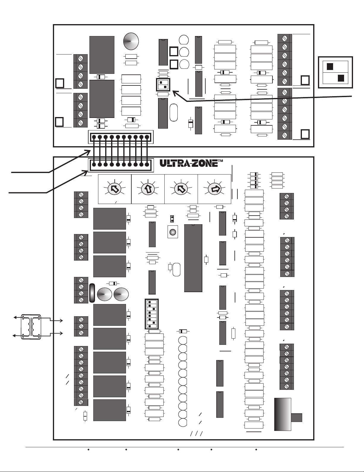
Setting the XM2
Expansion Panel
DIP Switches
Each expansion
module has a 2
position DIP
switch. Factory
set to insure the
main module
recognizes each
expansion
module in the
proper
sequence.
FACTORY
SUPPLIED
POWER & DATA
POLARIZED
BUS CABLE
Protective
header caps not
shown for clarity
DO NOT CONNECT
OR DISCONNECT
BUS CABLE
WHILE THE PANEL
IS POWERED.
Provide Over-Current
Protection
To
Line
Voltage
24 vac transformer
W1
W2
12
EWC Controls Inc. 385 Highway 33 Englishtown, NJ 07726 800-446-3110 FAX 732-446-5362 E-Mail- [email protected]
XM2
rev B
D
M6
M
M4
P
R
M2
M1
D
M6
M
M4
P
R
M2
M1
M6
M4
M2
M1
M6
M4
M2
M1
M6
M4
M2
M1
Y2
Y1
RH
RC
E
ZONE3
MOTOR
ZONE2
MOTOR
ZONE1
MOTOR
24
T’FORMER
R
C
SYSTEM
G
O
B
E
C
RH
RC
LINK
W
J
1
J
VAC
C
1
C
+
K
1
3
D
K
2
2
D
1
D
21
STAGING
TIMER
D
+
C
28
OAS
4
1
14
7
OFF
R
1
F1
CONTROLS INC.
Englishtown, NJ
BMPlus5000
1
Z
U
1
R
1
2
R
R
3
R
4
R
5
U
5
R
6
1
R
17
W
E
CONTROL
43
40
37
35
42
34
2
R
K
1
1
D
K
2
2
D
K
3
3
D
+
2
C
SW
K
4
D
5
R
5
K
R
20
21
R
D
6
R
22
K
6
R
R
25
R
R
7
D
R
27
7
K
R
29
R
R
D
8
R
31
K
8
R
R
33
R
D
9
46
49
52
LIMIT
5
C
R
R
16
U
1
C
U
9
3
19
23
24
26
28
30
32
34
BMPlus3000 rev B
STATUS
R
40
R
39
0
A
<
0
A
<
R
38
Y
1
CONTROLS INC.
C
140
130
120
110
HIGH
LIMIT
R
3
15
RESET
R
13
12
13
C
1
Y
HP
SYSTEM
<
DF
HP
<
TSTATS
HC
<
O
RV
<
OAS
STAGING
<
50
OFF
<
SAS
OFF
<
FAN
GAS
< >
1
LED
2
LED
3
LED
4
LED
5
LED
LED
6
7
LED
8
LED
9
LED
10
LED
11
LED
1
>
2
>
D
8
TEMPLOW TEMP
7
C
8
C
R
14
>
>
RULE
%
>
U
150
>
CONV
>
STATUS
OAS
SAS
ZONE
ZONE
ZONE
FAN
Y
Y
U
4
R
R
R
3
C
3
U
2
R
R
R
SYSTEM
19
160
12
170
5
ND STAGE HEAT
2
DIFFERENTIAL
R
4
2
U
11
C
OTHER
HP
B
TIMER
>
ON
>
ON
HYDRONIC
Z
1
3
2
1
2
1
B
1
W
EM
W
2
ZONE3
T
ZONE2
T
ZONE1
T
4
SW
R
R
R
R
STAT
STAT
STAT
C
W/E
O/B
Y
R
G
C
W/E
O/B
Y
R
G
36
37
38
39
SAS
SAS
OAS
OAS
C
W/E
O/B
Y
R
G
C
W/E
O/B
Y
R
G
C
W/E
O/B
Y
R
G
ONE
ZONE
EM
NORM
T
S
T
A
T
T
S
T
A
T
Figure 20
DIP switch
settings
for 1st
Expansion
panel.
Zones 4 & 5
R
19
21
R
R
12
11
10
D
6
R
30
29
28
4
D
34
26
33
40
47
C
3
U
10
C
4
U
5
U
6
U
7
U
8
U
14
R
13
R
15
7
D
16
R
R
36
R
37
R
22
R
20
R
26
25
R
R
27
D
5
R
24
R
35
10
D
11
D
12
D
13
D
15
21
D
C
14
R
66
C
9
R
35
R
70
73
R
R
72
R
77
R
76
R
23
R
18
R
41
R
42
R
43
R
40
R
82
R
81
R
44
R
45
46
R
R
47
48
R
R
49
R
50
R
51
52
R
R
53
R
79
R
78
54
R
R
55
R
56
57
R
58
R
R
59
R
60
R
61
62
R
R
63
R
71
R
64
65
R
68
R
R
67
R
69
Page 13
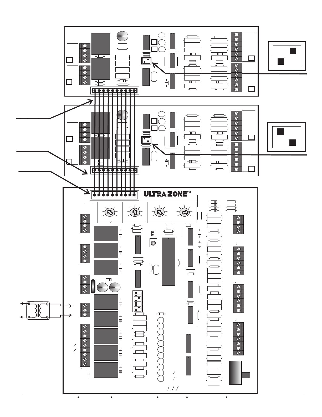
Setting the XM2
Expansion Panel
DIP Switches
Each expansion
panel has a 2
position DIP switch.
Factory set to insure
the main module
recognizes each
expansion module in
the proper sequence.
FACTORY
SUPPLIED
POWER & DATA
POLARIZED
BUS CABLE
Protective
header caps not
shown for clarity
DO NOT CONNECT
OR DISCONNECT
BUS CABLE
WHILE THE PANEL
IS POWERED.
Provide Over-Current
Protection
To
Line
Voltage
24 vac transformer
EWC Controls Inc. 385 Highway 33 Englishtown, NJ 07726 800-446-3110 FAX 732-446-5362 E-Mail- [email protected]
W1
W2
E
D
M
P
R
D
M
P
R
D
M
P
R
D
M
P
R
XM2
rev B
M6
M4
M2
M1
M6
M4
M2
M1
XM2
rev B
M6
M4
M2
M1
M6
M4
M2
M1
M6
M4
M2
M1
M6
M4
M2
M1
M6
M4
M2
M1
T’FORMER
R
C
G
Y2
Y1
O
B
E
RH
RC
C
RC
W
J
J
J
ZONE3
MOTOR
ZONE2
MOTOR
ZONE1
MOTOR
24
VAC
SYSTEM
RH
LINK
C
1
1
1
7
OFF
R
F1
CONTROLS INC.
Englishtown, NJ
BMPlus7000
1
C
+
K
1
3
D
K
2
2
D
1
D
U
R
1
2
R
R
3
R
4
R
5
U
5
R
6
Z
1
R
17
E
1
C
+
K
1
3
D
K
2
2
D
1
D
U
R
1
2
R
R
3
R
4
R
5
U
5
R
6
Z
1
R
17
E
21
28
14
STAGING
TIMER
OAS
1
4
D
+
1
C
43
40
37
35
34
42
2
R
K
1
1
D
K
2
2
D
K
3
3
D
+
2
C
K
4
D
5
5
K
R
R
D
6
R
K
6
R
7
D
R
7
K
R
D
8
R
K
8
R
D
9
46
LIMIT
C
U
1
U
9
3
SW
R
19
20
21
22
R
23
R
24
25
R
26
27
R
28
29
R
30
31
R
32
33
34
R
BMPlus3000 rev B
STATUS
1
R
40
R
39
0
A
>
<
0
A
<
>
R
38
Y
1
D
CONTROLS INC.
C
W
STATUS
1
R
40
R
39
0
A
>
<
0
A
<
>
R
38
Y
1
D
CONTROLS INC.
C
W
CONTROL
140
130
120
49
110
52
5
R
R
TEMPLOW TEMP
HIGH
LIMIT
R
3
C
C
15
16
R
14
RESET
R
13
12
C
13
C
1
Y
HP
SYSTEM
<
DF
HP
CONV
>
<
TSTATS
HC
<
O
RV
<
>
STAGING
OAS
<
50
OFF
OFF
GAS
<
SAS
<
FAN
< >
1
LED
2
LED
3
LED
4
LED
5
LED
LED
6
7
LED
8
LED
9
LED
10
LED
11
LED
RULE
%
>
U
3
C
U
3
1
2
8
U
3
C
U
3
1
2
8
SYSTEM
150
160
170
7
8
OTHER
>
HP
>
B
>
TIMER
>
ON
HYDRONIC
Z
STATUS
OAS
SAS
ZONE
ZONE
ZONE
FAN
Y
2
Y
1
1
W
W
2
4
U
2
4
U
2
19
12
5
2
R
4
ON
1
12
R
R
11
R
10
D
6
R
30
29
R
R
28
4
D
R
34
12
R
R
11
R
10
D
6
R
30
29
R
R
28
4
D
R
34
26
ND STAGE HEAT
DIFFERENTIAL
3
U
2
U
4
U
11
C
5
U
6
U
7
U
3
2
1
8
U
B
EM
18
18
42
46
47
49
51
52
56
57
59
61
62
65
ZONE3
T
ZONE2
T
ZONE1
T
SW
STAT
STAT
STAT
4
R
R
R
R
36
37
38
39
C
W/E
O/B
Y
R
G
C
W/E
O/B
Y
R
G
C
W/E
O/B
Y
R
G
C
W/E
O/B
Y
R
G
T
S
T
A
T
T
S
T
A
T
T
S
T
A
T
T
S
T
A
T
SAS
SAS
OAS
OAS
C
W/E
O/B
Y
R
G
C
W/E
O/B
Y
R
G
C
W/E
O/B
Y
R
G
ONE
ZONE
EM
NORM
DIP switch settings for
2nd Expansion panel.
Zones 6 & 7
DIP switch settings for
1st Expansion panel.
Zones 4 & 5
Figure 21
R
19
21
R
R
14
R
13
R
15
7
D
16
R
R
36
R
37
R
22
R
20
R
26
25
R
R
27
D
5
R
24
R
35
R
19
21
R
R
14
R
13
R
15
7
D
16
R
R
36
R
37
R
22
R
20
R
26
25
R
R
27
D
5
R
24
R
35
10
D
11
D
33
12
D
13
D
40
47
15
C
21
D
10
C
C
14
R
66
C
9
R
35
R
70
73
R
R
72
R
77
R
76
R
23
R
R
23
R
R
41
R
R
43
R
40
R
82
R
81
R
44
R
45
R
R
48
R
R
R
50
R
R
R
53
R
79
R
78
54
R
R
55
R
R
58
R
R
R
60
R
R
R
63
R
71
R
64
R
68
R
R
67
R
69
13
Page 14
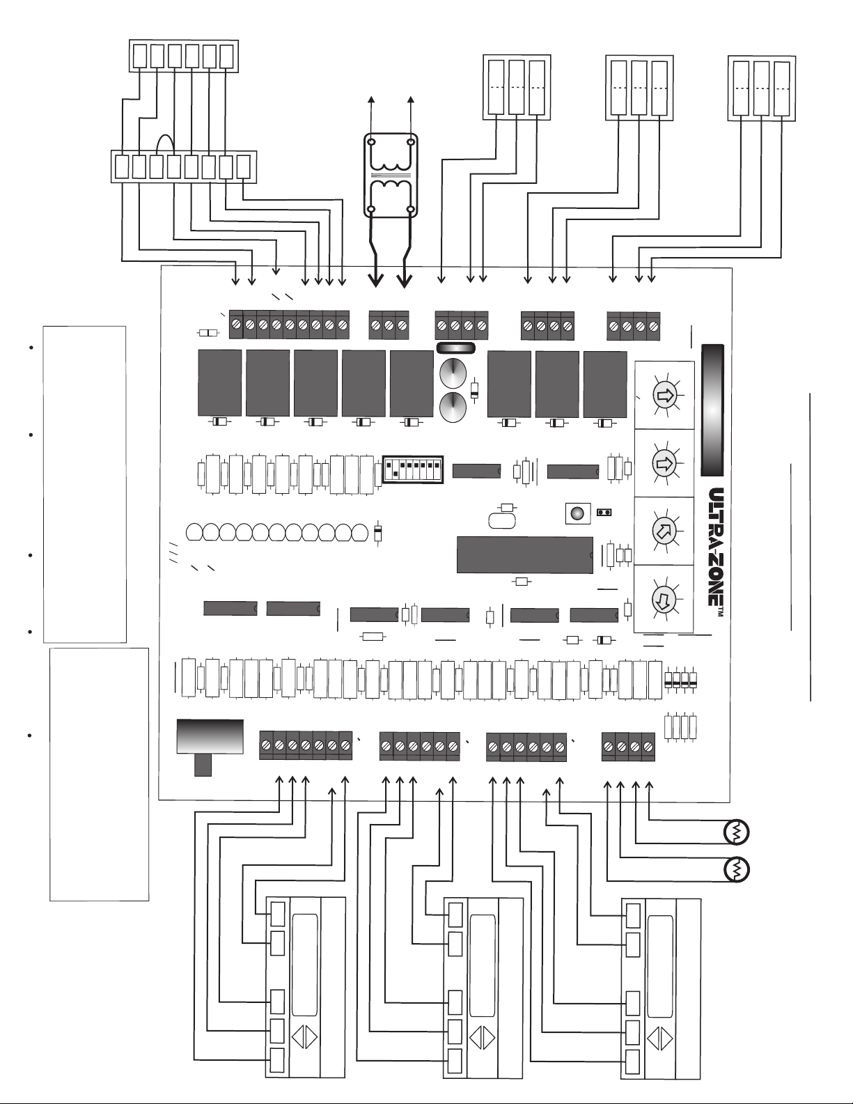
HEAT
OUT
X
O/
Y1
Y
C
R
/
W
B
O/
W
W
R
C
2
Y
1
1
B
DOOR
PU
2
M
P
2
S
FU
TA
R
Y
2
G
N
G
E G
A
C
E
AS
2
4
va
c t
4
0va
ra
ns
fo
rme
T
Pr
P
o
r
o
ot
Li
vi
n
ecti
de
e
Volt
O
on.
ver
ag
-Cu
e
.
r
r
ent
C
O
M
1
P
P
O
C
4
6
C
O
M
1
P
O
4
N
D /
P
U
C
RD
6
DA
C
O
M
1
P
P
O
C
4
6
MP
ERS
r
EW
C
C
o
nt
r
ols
In
ELECT
c.
3
8
5
Hi
R
gh
I
C
way
S
H
33
O
CK
E
n
O
gl
is
R
ht
EQ
o
wn,
UI
N
P
J
0
MEN
77
2
6
T
80
DAM
0
-
4
46
A
-31
GE.
1
0
F
AX
e
7
a
32
c
h
-44
cont
6
-
5
362
rol.
E-M
ai
l
i
n
fo
@e
wcco
ntr
o
l
s
.com
WA
F
V
O
O
R
RNING:
LT
U
AG
S
E
ES!
W
T
ITH
U S
HE
S
24
E P
E C
VAC
A
NE
.
A
DO
UTI O
L
S
N
AR
O
N
T
E
USE O
T
DES
O
AV OID
I
G
THER
N
E
D
n
col
nu
a
t
m
o
i
o
r
b
-co
n
e
a
r to
l co
d
e
num
d
d
, mult
e
s
a
ber
n
i
d
-co
or
ordi
ndu
l
ett
nance
e
ct
r
o
t
o
r wi
le
s
. U
r
t
ter
e.
s
Wi
e
o
n
re
E
W
C
Eng
C
O
N
l
i
T
s
R
h
OLS
t
o
w
n
IN
,
N
C
J
.
BMPlus3000 rev B
R
Al
l
wi
r
i
ng
shoul
d
b
e
done
to
l
o
c
a
l and
76
S
W
4
N
O
R
M
C
R
C
L
I
R
N
H
K
D
9
R
34
L
ED
1
1
W
2
E
M
R
77
D
8
K
8
R
R
33
31
R
3
2
LE
L
L
E
E
D
D
D
10
9
8
Y
Y
W
2
1
1
B
R
R
72
7
R
0
73
E
M
W1
W
2
R
R
C
H
E
R
29
R
R
3
2
0
8
L
E
D
7
F
A
N
U
8
Y
Y2
O
1
B
D
7
K
7
R
27
L
E
D
6
Z
O
N
E
1
K
6
R
25
R
R
R
2
2
2
6
3
4
LED
L
LED
E
D
4
3
5
SAS
ZON
ZON
E
E
2
3
U
7
C
G
S
Y
S
T
E
M
D
6
R
22
L
E
D
2
O
A
S
D
5
K
5
R
R
2
20
R
1
1
9
O
GA
F
F
S
<
<
L
E
S
F
D
A
1
A
N
S
>
>
O
HY
N
S
DR
TAT
Z
ONI
1
U
C
S
U
6
R
35
M
M
M
R
T
’FO
2
4
R
VA
M
C
E
R
M
1
2
4
6
F1
C
D
+
1
4
C
+
2
K
4
SW
3
O
O
HP
D
H
O
F
A
C
F
F
S
<
<
<
<
<
<
S
T
H
50
R
Y
S
P
S
S
TA
V
T
%
>
TE
A
G
TS
>
RU
C
M
I
>
NG
>
O
B
L
N
>
O
E
H
V
THE
P
>
TI
ME
O
R
N
R
U
5
C
R
9
66
M
M
M
M
1
2
4
M
Z
ON
OT
O
E
R
1
D
3
K
3
U
9
C
12
C
1
3
Y
1
C
14
6
D
2
K
2
R
13
R
E
S
E
T
C
1
1
U
4
C
1
0
M
M
M4
M6
1
M
O
TO
R
D
1
U
1
U
2
2
Z
O
N
E2
K
1
R
R
16
1
5
R
1
C
4
8
U
3
D
21
MO
Z
ON
T
O
E
R
3
OF
R
7
1
F
TIM
S
ER
T
A
G
I
NG
O
AS
4
3
2
5
3
R
3
7
2
4
L
OW
L
I
MI
T
E
T
M
P
C
5
C
7
C
1
5
4
5
9
2
1
1
R
1
2
3
0
0
HI
GH
L
I
M
T
I
T
E
M
P
1
1
7
6
0
0
1
R
2
5
4
2
D
N
I
D
F
STAG
FE
R
E
N
E
T
H
I
A
E
L
A
4
4
T
7
0
D
13
J
1
1
4
2
1
2
8
4
0
4
3
4
6
C
ON
1
3
0
T
1
4
R
0
O
1
L
5
0
SYS
1
9
T
EM
2
6
3
3
D
D
D
1
1
1
1
2
0
H
e
a
t
Pu
m
p
T
her
mo
s
t
at Em
er
g
e
n
cy In
p
u
t
Ou
t
d
o
o
r a
i
r
T
e
m
p
era
tur
e
or
BM
Pl
us
A
Dual
u
3
xili
0
a
F
r
0
y H
uel
0
e
Wi
at
Hea
A
ct
r
in
i
t P
v
ate
g
ump
s v
Di
i
a
a
g
ra
m
R
R
R
64
7
6
1
8
R
R
R
6
69
65
7
O
G
R
Y
Z
O
N
E
N
E
C
W
O/
B
H
E
AT
7
0
Y
R
G
R
R
60
R
R
6
62
3
W
/
E
Z
ON
E
1 TH
E
RM
O
S
TAT
58
R
R
61
C
R
5
5
9
7
Z
T
ON
S
T
E1
A
T
G
R
R
5
79
4
R
R
W
/E
R
R
53
78
52
ZONE
T
STA
T
2
C
G
C
H
EAT
R
55
56
R
Y
O
/B
W
7
2
Y
R
G
R
R
5
48
0
R
R
5
4
1
9
R
Y
O
/
B
ZO
NE
2
THER
M
O
STAT
W
/
E
R
R
R
4
8
40
4
2
R
R
R
4
47
4
5
6
Z
T
O
S
N
T
E3
A
T
C
R
R
8
1
O
A
S
R
R
43
4
4
1
2
R
R
R
R
3
37
38
3
9
O
SA
S
AS
A
S
S
C
W
Y
R
G
6
S
U
PP
L
Y
A
I
R
SE
NS
OR
O
U
T
D
O
O
R
AIR S
E
NSO
Z
H
O
EA
NE 3
T
T
HER
6
8
M
O
S
T
A
T
R
Page 15
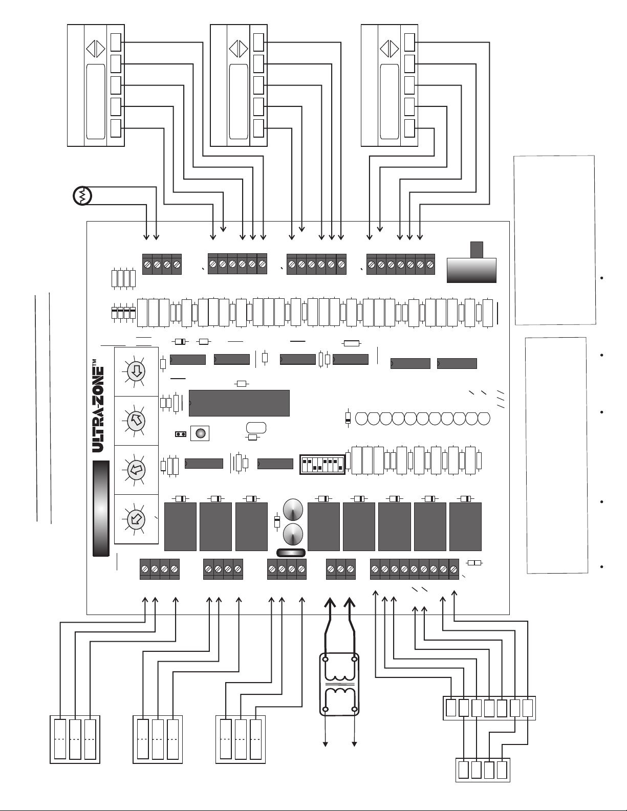
GR
GR
GR
m
a
r
g
ia
D
g
rin
i
W
000
s 3
lu
P
M
B
C
/
A
E
G
TA
S
WITH 2
AT
HE
AS
G
GE
A
T
S
2
68
YW
C
HEAT
ZONE 3 THERMOSTAT
R
O
S
N
E
S
IR
A
Y
L
P
SUP
SAS
SAS
OAS
36
38
37
39
R
R
R
R
41
R
a
i
v
es
at
v
i
t
Ac
.
r
me
Cool
Ti
ble
tage
a
t
S
s
nd
2
Adju
&
e
t
h
a
T
He
age
2nd St
10
11
12
13
D
D
D
D
40
47
33
26
19
5
12
SYSTEM
160
170
150
140
130
110
120
CONTROL
1
J
52
49
46
43
40
34
37
35
42
28
21
14
7
ZONE3
MOTOR
OAS
STAT
T
ZONE3
42
R
ND STAGE HEAT
2
TEMPLOW TEMP
HIGH
STAGING
OFF
M6
81
43
R
15
C
DIFFERENTIAL
4
R
8
7
C
C
LIMIT
3
R
15
R
5
C
LIMIT
2
1
R
K
OAS
TIMER
1
R
M2
M4
45
R
R
40
82
44
R
R
R
21
D
10
C
3
U
2
U
14
R
16
R
1
U
2
K
1
D
ZONE2
MOTOR
M1
M6M4M2
72
YW
C
HEAT
ZONE 2 THERMOSTAT
C
W/E
O/B
YRG
ZONE2
49
46
47
R
R
4
U
RESET
51
52
R
48
R
11
C
13
R
12
C
3
K
2
D
53
R
R
R
50
R
14
C
5
1
Y
13
C
9
U
3
D
4
D
O/B
C
W/E
YRG
STAT
T
56
78
55
R
R
R
79
54
R
R
66
R
U
TIMER
HP
>
OTHER
B
>
CONV
>
>
STAGING
RV
HP
TSTATS
SYSTEM
<
<
<
<><
O
HC
DF
HP
OAS
3
SW
4
K
2
+
C
1
+
C
ZONE1
57
59
R
R
58
60
R
R
9
C
6
U
1
ON
Z
>
HYDRONIC
ON
RULE
>
%
FAN
50
SAS
< >
<
<
GAS
OFF
OFF
19
R
20
R
5
K
5
D
F1
ZONE1
MOTOR
M6
M1
M4
VAC
24
T’FORMER
R
M2
M1
C
70
YW
C
HEAT
ZONE 1 THERMOSTAT
.
es
l
a
c
lo
ne to
o
d
C
W/E
O/BYR
STAT
T
61
62
63
R
R
R
71
64
R
R
35
R
7
U
3
STATUS
1
LED
ZONE
SAS
OAS
4
3
2
LED
LED
LED
ZONE
G
ONE
EM
65
69
67
R
R
R
68
R
70
R
8
U
2
1
ZONE
5
LED
2
ZONE
FAN
Y
6
8
7
LED
LED
LED
NORM
77
73
R
R
76
72
R
R
EM
B
1
2
1
W
W
Y
9
10
11
LED
LED
LED
be
d
l
u
4
ho
SW
s
g
rin
wi
ll
A
BMPlus3000 rev B
26
24
23
R
R
R
22
21
R
25
R
R
6
K
6
D
7
D
30
28
R
27
R
7
K
32
34
R
R
29
R
8
D
R
31
33
R
R
8
K
9
D
CONTROLS INC.
Englishtown, NJ
C
RH
SYSTEM
G
Y2
Y1
E
B
O
RH
W2
W1
LINK
RC
C
RC
W
E
c
r
tor
n
o
c
.
u
na
i
d
r
o
d
an
s
e
od
c
l
na
o
ati
n
d
n
a
D
ER
E
H
T
GN
I
O
ES
D
RE
A
LS
NE
PA
E
HES
T
G:
IN
N
AR
W
ol
er
b
ond
ontr
c
ti
l
h c
o num
c
r t
d, mu
be
e
on ea
d
um
n
tter
-co
e
r
e
l
o
l
o
to
. Wir
er
e c
re
i
s
ett
l
w
U
RIC
CT
LE
E
SE
U
OID
T
E.
O
AV
N
MAG
TO
O
DA
ON
T
C. D
TI
N
A
E
U
V
A
24
C
PM
E
H
UI
S
Q
U
E
WIT
S!
R
E
O
K
USE
TAG
L
HOC
OR
S
VO
F
EWC Controls Inc. 385 Highway 33 Englishtown, NJ 07726 800-446-3110 FAX 732-446-5362 E-Mail- [email protected]
r
rme
o
f
s
a
n
v
S
R
E
6
4
1
PC
PO
COM
6
4
DAMP
D
UR
1
PC
PO
COM
ND /
6
4
1
PC
PO
COM
To Line Voltage.
a
r
t
0
4
ac
v
4
2
Provide Over-Current
Protection.
S
A
E
G
G
Y2
Y1
TAGE
FURNAC
S
2
G
R
IN
S
T
Y1
Y2
UNI
NDEN
OUTDOO
O
C
R
W1
R
C
W2
C
Page 16
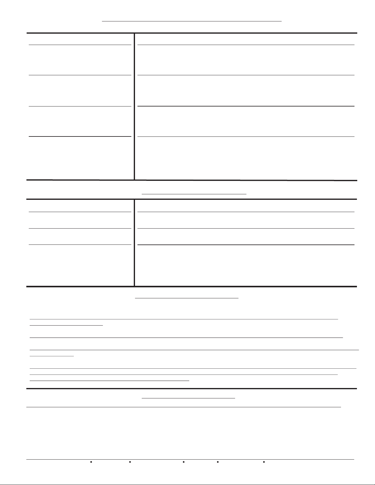
T R O U B L E S H O O T I N G
SYMPTOM
LED’S are responding properly but
HVAC system is malfunctioning.
LED’s are not responding properly
and HVAC system is malfunctioning.
LED’s illuminate and HVAC system
functions normally but dampers do
not respond.
LED’s do not illuminate and HVAC
system does not respond.
DETECTING 24vac SHORTS
HVAC system not responding and
BMPLUS 3000 LED’s are off.
Dampers not responding and THE
BMPLUS 3000 LED’s are off.
ISOLATING 24vac SHORTS
F1 circuit breaker protects the
BMPlus 3000 and reacts to a short in
the damper motor or thermostat
component and field wiring.
SOLUTIONS
Check HVAC system wiring for proper connections.
Check HVAC system wiring for shorts/miswiring.
Check HVAC System.
Refer to Technical Bulletin for correct Setup/Wiring/Dip Switch settings.
Check HVAC system wiring for shorts/miswiring.
Check HVAC system wiring for proper connections.
Check HVAC thermostat for proper connections.
Refer to Technical Bulletin for correct Setup/Wiring/Dip Switch settings.
Check damper motor wiring for proper connections.
Check damper motor 24vac transformer voltage/fuse/BMPlus circuit breaker.
Check damper motor wiring for shorts/miswiring.
Refer to Technical Bulletin for correct Setup/Wiring.
REFER TO THE DAMPER MOTOR TESTING PAGE 9
Check HVAC & BMPlus system transformer supply voltage.
Check HVAC & BMPlus system 24vac transformer voltage, fuse & the BMPlusB
circuit breaker.
Check HVAC & BMPlus system wiring for shorts/miswiring.
CHECK YOUR WIRING
SYMPTOMS: Module(s) appear to be dead!
If 24vac short has occurred, 24vac will be present at the BMPlus 3000 Module
Input terminals R & C; but 24vac will not be present at the Thermostat R&C.
SOLUTIONS: Remove 24vac power from BMPlus 3000 and allow circuit breaker to cool!
Find and repair short(s) in damper and/or thermostat field wiring. Restore 24 vac power.
Disconnect the wire(s) from the ‘R’ terminals on the BMPlus 3000 thermostat
terminal blocks , and the “M2/M4/M6’’ terminals on the BMPlus 3000 damper
motor terminal blocks. Restore power. If the short is no longer present, Ohm
out the thermostat and damper field wiring for shorts/misconnections. Replace
or repair wires as necessary. Restore power. Module(s) will resume operation.
TESTING THERMOSTATS
Check to make sure that the thermostat Rc and Rh terminals are connected together, unless your application requires
separation of these circuits.
Use the (C) Common terminal provided at each thermostat terminal block to wire up full 24 vac hard-wired thermostats.
You should reference the (C) Common terminal when troubleshooting incoming thermostat demand signals, even if no wire is
connected there.
Make sure that you wire and configure your thermostats for the correct application. Most thermostats built today can be field
configured to operate as regular Heat/ Cool type or as Heat Pump type. Remember that you can use regular Heat/Cool
thermostats on the BMPlus 3000 for Heat Pump applications.
TECHNICAL SUPPORT
EWC Controls provides superior toll free Troubleshooting Support for the BMPlus 3000 when you are on the job site!
Call 1-800-446-3110 Monday - Friday 8am to 5pm EST
Otherwise call 1-732-446-3110 for information on the BMPlus 3000 and other ULTRA-ZONE products..
When calling for Technical Support, please have a multi-meter, pocket screwdriver, and wire cutter/stripper handy.
16
EWC Controls Inc. 385 Highway 33 Englishtown, NJ 07726 800-446-3110 FAX 732-446-5362 E-Mail- [email protected]
 Loading...