

Ewave SuperSCREAMER, SCREAMER 422, BaseWAVE, STAMPER Technical Manual

EWAVE Inc.
7419 Gracefield Ln.
Dallas, Texas 75248
(972) 248-2931
www.electrowave.com
Ewave Radio Modem Technical Manual
Version 1.02
Ewave Radio Modems covered in this manual:
SuperSCREAMER
BaseWAVE
SCREAMER 422
STAMPER

Ewave Radio Modem User’s Manual V1.02
1 OVERVIEW.......................................................................................................................................... 3
2 INSTALLATION.................................................................................................................................. 5
3 THEORY OF OPERATION ............................................................................................................... 6
3.1 A
3.2 C
3.3 LED
3.4 C
3.5 C
3.6 F
3.7 E
3.8 C
3.9 T
NATOMY OF AN EWAVE RADIO MODEM ....................................................................................... 6
ONNECTOR PIN-OUTS .................................................................................................................... 7
S............................................................................................................................................... 7
ONNECTION TO PARALLAX BASIC STAMP FOR REMOTE-DEBUGGING &REMOTE-PROGRAMMING7
HARACTERISTICSOF PACKET RADIO COMMUNICATION................................................................ 8
INE-TUNING THE EWAVE RADIO MODEM FOR YOUR APPLICATION ............................................... 9
WAVE RADIO MODEM PROTOCOL CONFIGURATIONS .................................................................. 10
OMMAND STATE VS.DATA STATE............................................................................................... 11
HE SUPERSCREAMER™ WITH DYNAMIC PROTOCOLSUPPORT ............................................... 12
4 COMMANDS...................................................................................................................................... 13
4.1 QUERY SETTINGS..................................................................................................................... 13
4.2 QUERY VERSION...................................................................................................................... 13
4.3 QUERY STATION TYPE ........................................................................................................... 14
4.4 SET MODE OF MODEM (E
NHANCED SCREAMER ONLY)...................................................... 14
4.5 ATTENTION ON/OFF................................................................................................................. 14
4.6 TX POWER ON/OFF................................................................................................................... 15
4.7 RETRY ON/OFF.......................................................................................................................... 15
4.8 SET CHANNEL........................................................................................................................... 15
4.9 SET PACKET SIZE THRESHOLD ............................................................................................. 15
4.10 SET WAIT-TIME BEFORE TRANSMITT AL............................................................................ 16
4.11 SAVE DEF AULT SETT INGS TO EEPROM.............................................................................. 16
4.12 SET BAUD RATE ....................................................................................................................... 16
5 SPECIFICATIONS............................................................................................................................ 17
6 TRANSMIT FREQUENCIES...........................................................................................................18
7 ORDERING INFORMATION.......................................................................................................... 19
8 OEM OPTIONS.................................................................................................................................. 19
9 REVISION HISTORY ....................................................................................................................... 20
Copyright © 2001 by Ewave, Inc.2
Ewave Radio Modem User’s Manual V1.02
1 Overview
The Ewave family of wireless radio-frequency data m odems are
designed for systems requiring the full-duplex transmission and
reception of wireless data. All Ewave family members are based on
the RF10K™ core. T he RF10K™ core uses our 900 MHz fullduplex transceiver, coupled with our proprietary dual RISC
processor modulation/demodulation engine. E wave Radio Modems
are available in several supply voltages and support standard serial
interfaces using RS232, RS422, or TTL voltage levels. An Ewave
Radio M odem can be used in any application where a wireless data
link is needed -- the full duplex design allows the modem to be a
drop-in replacement for an existing wired serial link. The Ewave
Radio Modem’s low power requirements also makes it an ideal
solution for battery-powered applications.
Features of the Ewave Radio Modem:
• FCC certified; no user license required.
• Full duplex, allowing simultaneous transmission and
reception of data.
• Programmable baud rates, up to 38.4K.
• 9600 bps sustained data throughput (higher data rate
available if transparent 16-bit CRC is disabled).
• Up to 40 channels, software selectable.
• Transparent, simple operation: Looks like a serial cable to
your application.
• Transparent p rotection from errors and interference via 16-bit CRC (Cyclic Redundancy Code;
optional).
• High data reliability via transparent, automatic Retry/Acknowledge (optional).
• Dynamic packetization of data, providing low latency while maintaining high throughput.
• Packetization configurable via software parameters: Maximum Packet-Size Threshold and Next-
Byte Wait Time.
• Commands may be sent on-the-fly (e.g., Transmit Po wer On/Off, Channel) or modem may be
configured once and “locked” in the Data state for maximum transparency to your application.
• Fully integrated antenna.
• Operation from regulated 5V or unregulated ~7.2-10VDC (in which case the modem can supply
5V to another device). 3.3V also available – see Ordering Information at end of document.
• Non-volatile storage of user parameters (e.g., Channel, Baud Rate).
• Status LEDs indicating Transmit and Receive Activity, Transmitter Power On/Off and
Command/Data Mode.
• Support for RS232 “Break” conditions and RTS/CTS control signals.
Ewave Radio Modems are available in the following configurations:
• Data Interface:
• RS232
• RS422
• TTL
• Protocol Support:
• Normal transparent data mode (fastest data throughput)
• High-reliability mode with CRC and automatic retry/acknowledgement
• Parallax PBASIC mode (for remote-debugging/remote-download with Parallax’s Basic
Stamp)
• RM2000 mode (for use with Innovation First Robot Controller System; see
http://www.innovationfirst.com)
Copyright © 2001 by Ewave, Inc.3

Ewave Radio Modem User’s Manual V1.02
• An Enhanced Modem is also available which includes all the above Protocol features in one
Modem, and allows software feature selection on-the-fly.
• Supply Voltage:
• +5VDC supply voltage (3.3VDC also available) 140mA.
• +7.2-10VDC supply voltage (unregulated) 140mA.
• Packaging:
• Industrial-strength ABS case
• OEM module (without case)
Copyright © 2001 by Ewave, Inc.4

Ewave Radio Modem User’s Manual V1.02
2 Installation
There are no special installation requirements for the E wave Radio Modems, however, for best
performance, the modems’ antennae should be oriented parallel to each other and perpendicular to the
ground.
Please refer to Ewave’s On-line Support Center at http://www.electrowave.com/support.shtml for help with
installation or troubleshooting problems.
Copyright © 2001 by Ewave, Inc.5

Ewave Radio Modem User’s Manual V1.02
3 Theory of Operation
3.1
Anatomy of an Ewave Radio Modem
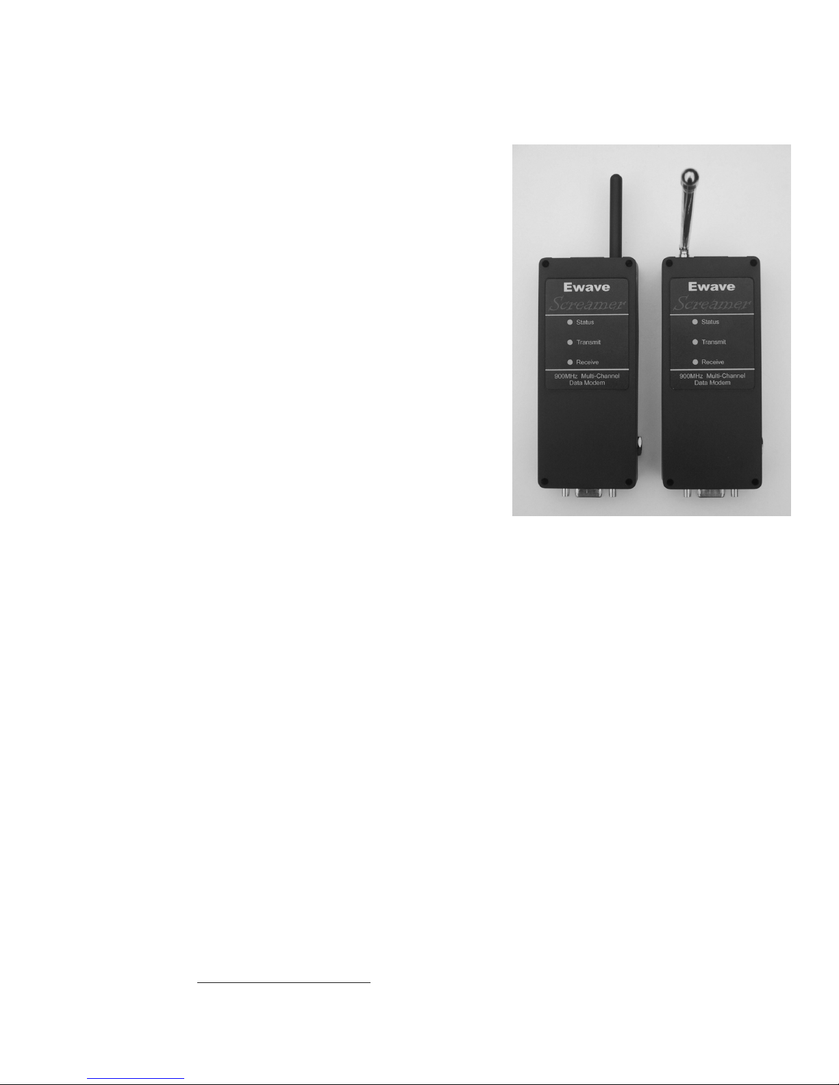
The picture below shows one of the two t ypes of Ewave packet radio modems, which are arbitrarily
referred to as Mobile (short flexible black antenna) and Base (longer swiveling chrome antenna). The
“Mobile” or “Base” units are interchangeable -- in any system either or both units can be fixed or portable
(though the Mobile’s short flexible antenna lends itself to portable use). However, it is important to note
that a Mobile unit will not communicate directly with another Mobile and likewise a Base unit will not
communicate directly with another Base. This is a necessary consequence of the fact that the modems are
full-duplex (meaning data may be transmitted and received simultaneously): T o allow full-duplex
operation, the Base and Mobile units contain matched pairs of t he Ewave RF transceiver module which are
optimized to transmit on a different range of frequencies (e.g., the Base units transmit on 926-928 MHz
while the Mobile units transmit on 902-904 MHz. The exact frequencies for each channel are listed in the
appendix.)
Note that it is possible to implement various “multi-drop” or “multi-node networks” schemes with the
Ewave Radio Modems – a single modem of one type communicating with several of the opposite type. For
example, this can be done through on-the-fly control of Transmit Po wer.
The picture at left shows a Mobile Ewave Radio
Modem unit.
The DB9 connector supplies standard RS232 or
RS422 signals.
5V 140mA regulated power may also be supplied
via the DB9, or the modem may be powered by
unregulated DC (7.2-10V, 140mA) supplied via
the side plug. If this is done, regulated 5V will be
available via the DB9 and may be used to power
an external 5 Volt device.
Copyright © 2001 by Ewave, Inc.6
 Loading...