


EWAVE Inc.
7419 Gracefield Ln.
Dallas, Texas 75248
(972) 248-2931
www.electrowave.com
Ewave Radio Modem Technical Manual
Version 1.02
Ewave Radio Modems covered in this manual:
SuperSCREAMER
BaseWAVE
SCREAMER 422
STAMPER

Ewave Radio Modem User’s Manual V1.02
1 OVERVIEW.......................................................................................................................................... 3
2 INSTALLATION.................................................................................................................................. 5
3 THEORY OF OPERATION ............................................................................................................... 6
3.1 A
3.2 C
3.3 LED
3.4 C
3.5 C
3.6 F
3.7 E
3.8 C
3.9 T
NATOMY OF AN EWAVE RADIO MODEM ....................................................................................... 6
ONNECTOR PIN-OUTS .................................................................................................................... 7
S............................................................................................................................................... 7
ONNECTION TO PARALLAX BASIC STAMP FOR REMOTE-DEBUGGING &REMOTE-PROGRAMMING7
HARACTERISTICSOF PACKET RADIO COMMUNICATION................................................................ 8
INE-TUNING THE EWAVE RADIO MODEM FOR YOUR APPLICATION ............................................... 9
WAVE RADIO MODEM PROTOCOL CONFIGURATIONS .................................................................. 10
OMMAND STATE VS.DATA STATE............................................................................................... 11
HE SUPERSCREAMER™ WITH DYNAMIC PROTOCOLSUPPORT ............................................... 12
4 COMMANDS...................................................................................................................................... 13
4.1 QUERY SETTINGS..................................................................................................................... 13
4.2 QUERY VERSION...................................................................................................................... 13
4.3 QUERY STATION TYPE ........................................................................................................... 14
4.4 SET MODE OF MODEM (E
NHANCED SCREAMER ONLY)...................................................... 14
4.5 ATTENTION ON/OFF................................................................................................................. 14
4.6 TX POWER ON/OFF................................................................................................................... 15
4.7 RETRY ON/OFF.......................................................................................................................... 15
4.8 SET CHANNEL........................................................................................................................... 15
4.9 SET PACKET SIZE THRESHOLD ............................................................................................. 15
4.10 SET WAIT-TIME BEFORE TRANSMITT AL............................................................................ 16
4.11 SAVE DEF AULT SETT INGS TO EEPROM.............................................................................. 16
4.12 SET BAUD RATE ....................................................................................................................... 16
5 SPECIFICATIONS............................................................................................................................ 17
6 TRANSMIT FREQUENCIES...........................................................................................................18
7 ORDERING INFORMATION.......................................................................................................... 19
8 OEM OPTIONS.................................................................................................................................. 19
9 REVISION HISTORY ....................................................................................................................... 20
Copyright © 2001 by Ewave, Inc.2
Ewave Radio Modem User’s Manual V1.02
1 Overview
The Ewave family of wireless radio-frequency data m odems are
designed for systems requiring the full-duplex transmission and
reception of wireless data. All Ewave family members are based on
the RF10K™ core. T he RF10K™ core uses our 900 MHz fullduplex transceiver, coupled with our proprietary dual RISC
processor modulation/demodulation engine. E wave Radio Modems
are available in several supply voltages and support standard serial
interfaces using RS232, RS422, or TTL voltage levels. An Ewave
Radio M odem can be used in any application where a wireless data
link is needed -- the full duplex design allows the modem to be a
drop-in replacement for an existing wired serial link. The Ewave
Radio Modem’s low power requirements also makes it an ideal
solution for battery-powered applications.
Features of the Ewave Radio Modem:
• FCC certified; no user license required.
• Full duplex, allowing simultaneous transmission and
reception of data.
• Programmable baud rates, up to 38.4K.
• 9600 bps sustained data throughput (higher data rate
available if transparent 16-bit CRC is disabled).
• Up to 40 channels, software selectable.
• Transparent, simple operation: Looks like a serial cable to
your application.
• Transparent p rotection from errors and interference via 16-bit CRC (Cyclic Redundancy Code;
optional).
• High data reliability via transparent, automatic Retry/Acknowledge (optional).
• Dynamic packetization of data, providing low latency while maintaining high throughput.
• Packetization configurable via software parameters: Maximum Packet-Size Threshold and Next-
Byte Wait Time.
• Commands may be sent on-the-fly (e.g., Transmit Po wer On/Off, Channel) or modem may be
configured once and “locked” in the Data state for maximum transparency to your application.
• Fully integrated antenna.
• Operation from regulated 5V or unregulated ~7.2-10VDC (in which case the modem can supply
5V to another device). 3.3V also available – see Ordering Information at end of document.
• Non-volatile storage of user parameters (e.g., Channel, Baud Rate).
• Status LEDs indicating Transmit and Receive Activity, Transmitter Power On/Off and
Command/Data Mode.
• Support for RS232 “Break” conditions and RTS/CTS control signals.
Ewave Radio Modems are available in the following configurations:
• Data Interface:
• RS232
• RS422
• TTL
• Protocol Support:
• Normal transparent data mode (fastest data throughput)
• High-reliability mode with CRC and automatic retry/acknowledgement
• Parallax PBASIC mode (for remote-debugging/remote-download with Parallax’s Basic
Stamp)
• RM2000 mode (for use with Innovation First Robot Controller System; see
http://www.innovationfirst.com)
Copyright © 2001 by Ewave, Inc.3

Ewave Radio Modem User’s Manual V1.02
• An Enhanced Modem is also available which includes all the above Protocol features in one
Modem, and allows software feature selection on-the-fly.
• Supply Voltage:
• +5VDC supply voltage (3.3VDC also available) 140mA.
• +7.2-10VDC supply voltage (unregulated) 140mA.
• Packaging:
• Industrial-strength ABS case
• OEM module (without case)
Copyright © 2001 by Ewave, Inc.4

Ewave Radio Modem User’s Manual V1.02
2 Installation
There are no special installation requirements for the E wave Radio Modems, however, for best
performance, the modems’ antennae should be oriented parallel to each other and perpendicular to the
ground.
Please refer to Ewave’s On-line Support Center at http://www.electrowave.com/support.shtml for help with
installation or troubleshooting problems.
Copyright © 2001 by Ewave, Inc.5

Ewave Radio Modem User’s Manual V1.02
3 Theory of Operation
3.1
Anatomy of an Ewave Radio Modem
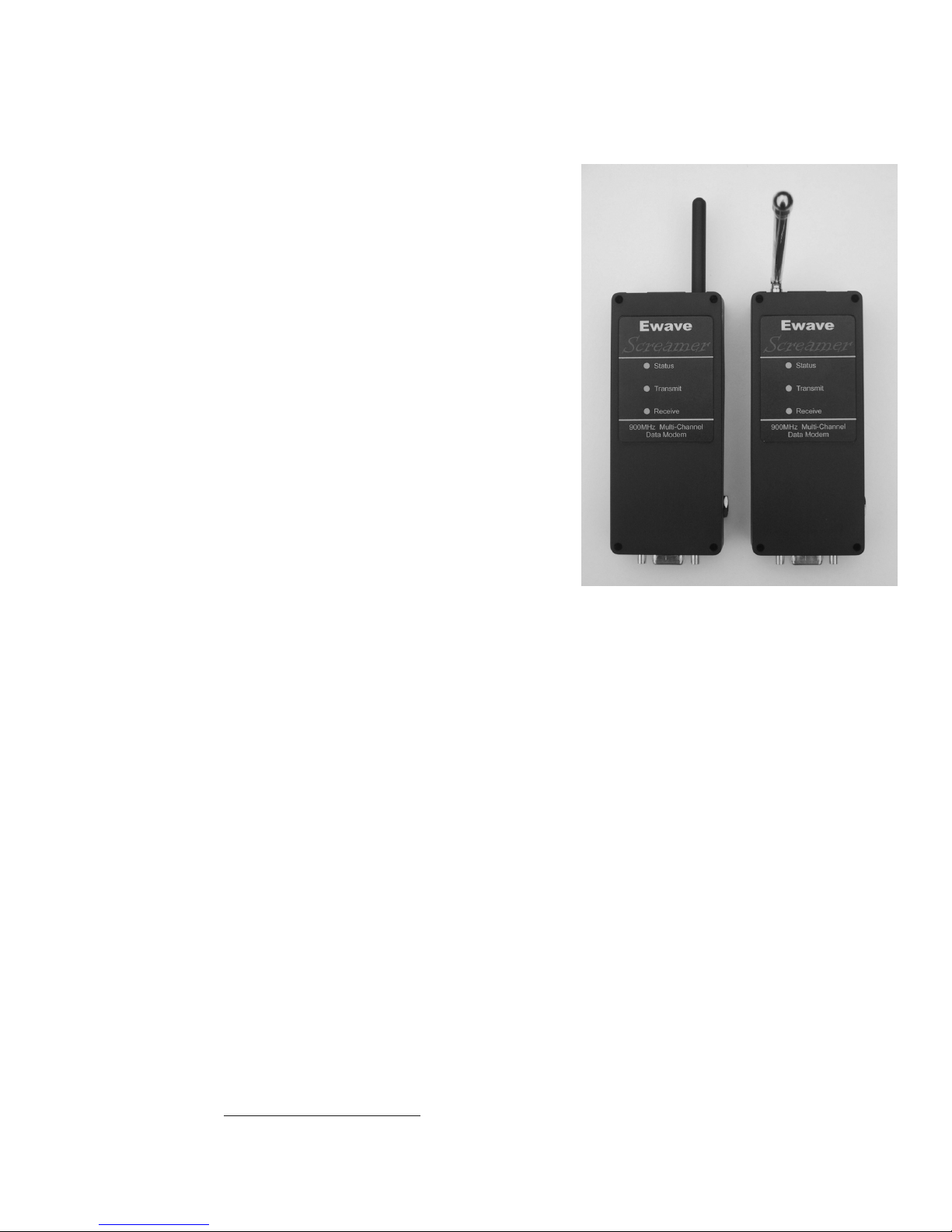
The picture below shows one of the two t ypes of Ewave packet radio modems, which are arbitrarily
referred to as Mobile (short flexible black antenna) and Base (longer swiveling chrome antenna). The
“Mobile” or “Base” units are interchangeable -- in any system either or both units can be fixed or portable
(though the Mobile’s short flexible antenna lends itself to portable use). However, it is important to note
that a Mobile unit will not communicate directly with another Mobile and likewise a Base unit will not
communicate directly with another Base. This is a necessary consequence of the fact that the modems are
full-duplex (meaning data may be transmitted and received simultaneously): T o allow full-duplex
operation, the Base and Mobile units contain matched pairs of t he Ewave RF transceiver module which are
optimized to transmit on a different range of frequencies (e.g., the Base units transmit on 926-928 MHz
while the Mobile units transmit on 902-904 MHz. The exact frequencies for each channel are listed in the
appendix.)
Note that it is possible to implement various “multi-drop” or “multi-node networks” schemes with the
Ewave Radio Modems – a single modem of one type communicating with several of the opposite type. For
example, this can be done through on-the-fly control of Transmit Po wer.
The picture at left shows a Mobile Ewave Radio
Modem unit.
The DB9 connector supplies standard RS232 or
RS422 signals.
5V 140mA regulated power may also be supplied
via the DB9, or the modem may be powered by
unregulated DC (7.2-10V, 140mA) supplied via
the side plug. If this is done, regulated 5V will be
available via the DB9 and may be used to power
an external 5 Volt device.
Copyright © 2001 by Ewave, Inc.6

Ewave Radio Modem User’s Manual V1.02
3.2 Connector Pin-outs
There are two different pin-outs for the Ewave Radio Modems. The pin out for the SuperScreamer,
BaseWave and Stamper is as follows:
The pin-out for the modem’s RS232 DB9 connector (either model, Base or Mobile) is as follows:
Both the Base and Mobile types of E wave Radio Modems configured for RS232 have Female DB9
connectors. This allows direct connection to a standard PC DB9 serial port via a straight-thru cable. When
connecting the Ewave Radio Modem to a PC-peripheral device (e.g., a mouse, trackball, digitizer) as a
drop-in wire replacement, a gender-changer and null-modem is usually required.
Please consult our web site www.electrowave.com for the pin out for the SCREAMER 422.
3.3 LEDs
The table below summarizes the meaning of the Ewave Radio Modem’s LEDs:
What it means… Status LED Transmit LED Receive LED
Modem is in Command state Rapid Blink * --- --TX Power is On --- ON
TX Power is Off, Modem in command state Rapid Blink * OFF
TX Power is Off, Modem in data state ON OFF --Modem is Actively Transmitting Data OFF FLASHING --Modem is Actively Receiving Data --- --- FLASHING
California Brownout OFF OFF OFF
* Rapid blink indication added for code version V1.39 or higher. Older versions LED is on solid.
3.4 Connection to Parallax Basic Stamp for Remote-Debugging & RemoteProgramming
In addition to providing a standard wireless link, the Ewave’s Stamper and SuperSCREAMER versions of
the Radio Modems may be used for remote-programming/remote-debugging of the Parallax Basic Stamp
Processors.
The diagram below shows how the two Ewave Radio Modems should be connected between the PC and the
PBASIC part:
Copyright © 2001 by Ewave, Inc.7

Ewave Radio Modem User’s Manual V1.02
3.5 Characteristics of Packet Radio Communication
The Ewave packet radio modem has been designed to be a transparent, drop-in replacement for a serial
connection, and employs a number of automatic optimizations for this purpose. Nevertheless, a basic
understanding of the underlying characteristics of radio packet communication will help the application
developer:
• properly configure the E wave Radio Modem for optimal performance in a particular application;
• rapidly diagnose problems; and
• improve the design of future applications for maximum performance or reliability within the limits of
radio communication imposed by Nature.
The Ewave Radio Modem provides a “full-duplex” communications channel (meaning data may flow in
either direction simultaneously) for 8-bit asynchronous serial data. In comparison to a hard-wired
connection, there are several important issues to be aware of whe n using the Ewave Radio Modems:
Latency, bandwidth, and errors.
3.5.1 Latency
Latency(ordelay)isthetimebetweenanactionandaresponse–e.g.,thetimebetweenwhenabyteissent
and when it is received by the other modem. With a hard-wired electrical connection, the latency is very
small (i.e., close to the speed of light.) With a Radio Modem latency is much greater for several reasons:
• A packet modem will typically transmit a “pre-amble” signal before transmitting the actual data,
to allow the receiver to synchronize to the data stream (or re-synchronize after an error). The
length of this “pre-amble” sets a lower limit on the delay between outputting a byte to the
transmitter and that same byte being output by the receiving modem.
• A packet modem will also typically attempt to transmit multiple bytes together as a unit, following
a single “pre-amble”. This is more efficient than generating a pre-amble for each data byte – in
Copyright © 2001 by Ewave, Inc.8

Ewave Radio Modem User’s Manual V1.02
fact, as the number of data bytes per packet increases, the time devoted to the pre-amble becomes
less significant, and overall efficiency increases. While this efficiency may not matter in some
applications (e.g., a sensor transmitting a few bytes once per second), it sets an upper limit on the
bandwidth of the channel and therefore is very important in some applications. So, a modem may
attempt to transmit “large” packet sizes – but this means the transmitting modem may need to
queue the first few data bytes until it has received a full packet’s worth of data instead of
beginning to transmit immediately. This adds to the latency on top of that due to the length of the
“pre-amble”.
• Finally, the internal design of the packet modem may add additional latency as data bytes are
moved from one internal FIFO to another. A quality packet modem, such as the Ewave Radio
Modem, will attempt to overlap or “pipeline” as many of these i nternal operations as possible to
minimize latency.
3.5.2 Bandwidth
Bandwidth is the rate of data bits transferred per unit time (e.g., bits per second). Typically, a radio modem
imposes a certain overhead due to the necessity of transmitting a “pre-amble” for synchronization,
command or “framing” bytes used to encode the data in packets, error checking codes or checksums for
error detection and/or correction, etc. Also, features such as retry/acknowledge (which may be enabled on
some Ewave Radio Modem models), while improving reliability, reduce the effective bandwidth when
errors or interference are present – because the modem must use some bandwidth to re-transmit alreadysent data or to transmit acknowledgements. In order to provide 9600 bps of data throughput, a radio
modem will typically transfer data “over-the-air” at a higher rate to compensate for the aforementioned
overhead. The Ewave Radio Modem transfers data “over-the-air” at approximately 10,000 bits / second.
3.5.3 Errors
Errors and interference are much more common in a wireless communications system compared to a wired
one. The effect of this is to increase latency and decrease bandwidth. For instance, if the Ewave Radio
Modem is programmed for automatic retry/acknowledge of data, a sufficient level of radio interference
may in effect increase the latency to infinity and decrease the bandwidth to zero. This is unavoidable, and
depending on the environment may even be common, so applications should be designed with appropriate
fail-safes, error checking and user-feedback.
3.6 Fine-Tuning the Ewave Radio Modem for your Application
This section discusses the features of the Ewave Radio Modem which may be used to fine-tune the modem
to your application.
3.6.1 CRCs – Protection from Interference
CRC’s (Cyclic Redundancy Codes) are a widely-used mechanism for detecting errors in communication
systems. Some Ewave Radio Modem models include automatic, transparent CRC generation and checking.
Without this feature, the Radio Modem may interpret random radio interference as valid received data –
which can confuse your application if it does not implement its own error checking. With this feature, the
Ewave Radio Modem automatically filters out radio interference. The corrupted packets will be silently
discarded. In many applications this is acceptable, but if it is not, the application mayeither implement its
own retry scheme or use the Ewave Radio Modem’s transparent Retry/Acknowledge (if the particular
Ewave Radio Modem model includes this feature.)
3.6.2 Packet Size Threshold
The packet size threshold parameter determines the number of bytes the Radio Modem will attempt to
assemble into a “packet.” Some applications tend to send fixed sized blocks of data and are sensitive to the
time between bytes within a single application-defined block. This parameter allows the application
Copyright © 2001 by Ewave, Inc.9

Ewave Radio Modem User’s Manual V1.02
developer to tell the Ewave Radio Modem what size data blocks to expect so that the modem may
packetize them as a unit and deliver them at the receiver with minimal and consistent delay between bytes.
For maximum throughput, the largest possible packet size threshold should be selected.
The Ewave Radio Modem also implements a partial packet timeout to automatically re-synchronize with
the application’s data block boundaries – if the packet size threshold is not reached within the Wait Time
(discussed below), the modem will transmit a smaller packet.
3.6.3 Wait Time before Transmittal
The W ait Time before Transmittal parameter determines how long the Ewave Radio Modem will wait for
the next byte before packetizing and transmitting the current data in its queue. This allows the application
developer to adjust the modem to the timing characteristics of the application.
This parameter should be set to zero to minimize latency – in this case, the Ewave Radio Modem will begin
transmitting as soon as a single byte is sent to the modem.
3.6.4 Retry/Acknowledge
The Ewave Radio Modems can implement an automatic Retry / Acknowledge scheme which i s transparent
to the application. This, combined with CRCs for error detection, greatly improves the reliability of data
transfer without requiring any changes to the application. However, note that in this mode, depending on
the level of interference, data may be delayed for arbitrarily long times. Applications which implement
their own protocol time-outs may need to be modified.
If the Ewave Radio Modem model implements Retries, each data packet will be automatically retransmitted until either an Acknowledgement packet is received from the other modem, or until the
application sends additional data to the transmitting modem, in which case the modem will give up retransmitting the old data and begin (re-)transmitting the new data in the same way.
The Ewave Radio Modem guards against duplication of data packets – from the application’s point-ofview, any data sent will be output from the other modem at most once.
3.7 Ewave Radio Modem Protocol Configurations
Ewave Radio Modems are available optimized for several different application protocols and
characteristics. Alternately, the Enhanced SuperSCREAMER™ is available which includes support for all
protocol features and allows the user to dynamically re-configure the modem on-the-fly.
The standard protocol configurations are:
Copyright © 2001 by Ewave, Inc.10

Ewave Radio Modem User’s Manual V1.02
Configuration
Name
“Fast” Maximum Data
“Checksum” High Reliability set by user set by user ON user
“Break” High Reliability
“RM2000” Fixed-Length
Description Packet Size
Threshold
(bytes)?
10 OFFOFF
Throughput with
Minimum
Latency
set by user set by user ON ON Remote
with RS232
“Break” and
RTS/CTS
Signalling
26 (fixed
Packets with CRC
but no Retries
size)
Wait before
Transmittal
(millisec.)?
complete
packet
CRC?Retry?Typical Use
Debugging &
Remote Download
of Parallax Basic
Stamps
OFF OFF Robot Control &
Telemetry
3.8 Command state vs. Data state
Normally the Ewave Radio Modem is in the Data state, in which all bytes sent to the modem via its serial
port are treated as user data and transmitted.
Depending on the configuration of the Ewave Radio Modem, it may also be possible to place the modem in
Command state. In this state, bytes sent to the modem via its serial port are interpreted as commands,
allowing on-the-fly reconfiguration of some or all modem settings and saving of modified settings in
EEPROM. The settings, which may be changed, depend on the protocol configuration of the Ewave Radio
Modem. The default factory Baud Rate is set to 9600 N81.
Whenever the modem enters Command state, or whenever the modem p rocesses a valid Command, it sends
a response of “OK” followed by a <CR><LF>. While in comma nd state, Radio Data reception is disabled.
Invalid commands result in a response of “ER”<CR><LF>.
Depending on the type of Radio Modem, different commands are available to the end user.
Exactly how or if Command state can be accessed depends on the modem’s protocol configuration and the
setting of the Attention flag. If the Attention flag is OFF, then regardless of protocol configuration the
modem can only enter Command state immediately after power is applied. The modem must be poweredup with RTS asserted, and then RTS must be toggled five times with less then 10 seconds between toggles.
See diagram below:
10 Seconds Max
RTS
Power On Command State
If any bytes are received on the modem’s serial port during this toggling sequence, the modem will
immediately e nter Data state (the received byte will be lost). To re-enter Command state, the modem must
once again be power cycled, with RTS asserted and the toggling sequence repeated.
Copyright © 2001 by Ewave, Inc.11

Ewave Radio Modem User’s Manual V1.02
For “Break”-configured modems with Attention ON, to enter Command state, apply power to the modem
with RTS asserted, then send a single byte to the serial port. The modem will enter Command state and
interpret the bytes received on the serial port as commands until RTS is de-asserted.
For all other configurations of modems with Attention ON, Command state may be entered by simply
asserting RTS. De-asserting RTS returns the modem to Data mode, and Command state may be re-entered
any number of times by re -asserting RTS.
3.9 The SuperSCREAMER™ with Dynamic Protocol Support
Regular Ewave Radio Modems are pre-programmed at the factory with firmware specific to their expected
use.
The Enhanced SuperSCREAMER includes support for all protocol capabilities in one unit, and may be
dynamically re-configured by the user. This is done using the MODE command (described below) which
is only available with the Enhanced SuperSCREAMER model.
Copyright © 2001 by Ewave, Inc.12

Ewave Radio Modem User’s Manual V1.02
4 Commands
This section describes the format of all Ewave Radio Modem commands. It assumes the modem has
already been placed in Command state as described above.
Commands consist of a single “command byte”, all of which are printable ASCII characters, followed by
zero or more “argument bytes”. In most cases, the argument bytes are also printable ASCII (for instance,
channel #’s are offset by 0x30 hexadecimal to make them printable), however in some cases this is not
possible because all 256 values are needed. All bytes which are not valid commands result in an “ER”
response from the modem.
The modem will respond with either “OK”<CR><LF> or “ER”<CR><LF> when it processes a command.
All commands except the “Dx” commands which update EEPROM should execute within 5 milliseconds
plus whatever time is required to transfer any response (in the case of the QUERY commands), which
varies depending on the current modem baud rate setting. The “Dx” commands should execute within 25
milliseconds.
4.1 QUERY SETTINGS
Send:
? Modem responds with a human-readable summary of its current settings.
Every line ends with a <CR><LF> and the entire output is terminated with a
final “OK”<CR><LF> to acknowledge the “?” command.
Example:
(user sends command… Note: no line-terminator is needed.)
?
(modem responds…)
www.electrowave.com, Ewave Inc.<CR><LF>
Ver 1.33 <CR><LF>
Mobl<CR><LF>
TX Power ON<CR><LF>
Attention OFF<CR><LF>
Retry ON <CR><LF>
Break Mode <CR><LF>
0x16 (F) Channel List<CR><LF>
0x00 (0) Packet Size<CR><LF>
0x30 Wait Time<CR><LF>
OK<CR><LF>
4.2 QUERY VERSION
Send:
V Modem responds with its firmware version number.
Example:
(user sends command… Note: no line-terminator is needed.)
V
(modem responds…)
Ver 1.33 <CR><LF>
OK<CR><LF>
Copyright © 2001 by Ewave, Inc.13

Ewave Radio Modem User’s Manual V1.02
4.3 QUERY STATION TYPE
Send:
S? Modem responds with its station type, either “Base”or“Mobl”, followed by
a <CR><LF>.
Example:
(user sends command… Note: no line-terminator is needed.)
S?
(modem responds…)
Mobl<CR><LF>
OK<CR><LF>
4.4 SET MODE OF MODEM (SuperSCREAMER Only)
Send:
Mf “Fast” mode, used for normal wireless link. Auto packetizes data, with
dynamic packet
sizes.
“Fast” mode is used when the highest speed data link possible is required.
Data packets are sent without internal checksums. The maximum data
throughput of the modem when it is in fast mode is 1035 bytes/second.
Mc “Checksum” mode, adds an 16 bit CRC to packets. Packets with invalid
CRC are discarded.
“Checksum” mode adds an internal CRC (cyclic redundancy code) to each
data packet. The receiving modem rejects packets with invalid CRCs. The
maximum data throughput when using Checksum mode is 964 bytes/second.
Mb “Break” mode. Used with Parallax parts, generates RS232 Break and RTS
to CTS outputs.
Break mode is used in applications that need to be able to send a serial Break
signal, and also send and receive RTS/CTS hardware handshake signals.
This mode is useful when using the Radio Modem to program and debug the
Parallax PBASIC products.
Mr RM2000 mode, used for the FIRST COMPETITION ROBOT
“RM2000” mode uses fixed-length datagrams to get maximum data
throughput. In this mode the data packets must follow a specific format.
This mode is currently used for the data link with the Innovation First
Robotics Controller. The maximum data throughput in this mode is 1071
bytes/second.
4.5 ATTENTION ON/OFF
Send:
An Set Attention On; modem responds to RTS-assertion by entering Command
state.
Af Set Attention Off; modem ignores RTS-assertion and treats RTS as a data
signal. Command state may only be entered at power-up.
Copyright © 2001 by Ewave, Inc.14

Ewave Radio Modem User’s Manual V1.02
4.6 TX POWER ON/OFF
Send:
Tn Transmitter Power On.
Tf Transmitter Power Off. Radio Modem can still receive incoming radio
packets while Tx Power is Off.
4.7 RETRY ON/OFF
Send:
Rn Retry/Ack. On; The modem will automatically re-send the data packet until
it is acknowledged by the other modem. If new data is sent to the modem
before the current data packet has been acknowledged, the retry-attempt is
aborted and the new data is processed.
Rf Retry/Ack. Off; Each data packet is transmitted exactly once.
4.8 SET CHANNEL
Send:
Cx,wherex is [0x31-0x58] Sets the current channel to (x – 0x30.)
While the modem is capable of using 40 channels, only 5 channels are available to the user in the standard
modems:
Channel # (1-40) Channel #
(in hex.)
4 0x04 C4 52 0x34
13 0x0D C= 61 0x3D
22 0x16 CF 70 0x46
31 0x1F CO (“See-letter-Oh”) 79 0x4F
40 0x28 CX 88 0x58
Both modems must be on the same channel to communicate.
Channel Command Channel Char.
in Decimal
Channel Char. in
Hex
4.9 SET PACKET SIZE THRESHOLD
Send:
Px,wherex is [0x31-0x58] Set the size threshold for data packets. How this parameter is interpreted
depends on the modem’s protocol configuration.
For “RM2000”-configured modems, (which uses fixed-length d ata packets), this parameter sets the length
of the data packets. In this case, x is 48 + the desired fixed-length packet size. Example: For a fixedlength packet size of 20 bytes, x would be 48 + 20 = 68, which in ASCII is “D”. Therefore the command
“PD” will set the fixed-length packet size to 20 bytes.
For “Checksum”- or “Break”-configured modem’s, (which send variable-sized data packets), this
parameter sets the maximum length – once this length is reached (or the Wait Time is exceeded) the packet
is transmitted. In this case, x is interpreted as a Boolean-mask as follows:
Copyright © 2001 by Ewave, Inc.15

Ewave Radio Modem User’s Manual V1.02
Desired Packet Size Threshold (in bytes) Value of x
(hex)
1 0x4F 79 PO (letter Oh)
20x4E78PN
40x4C76PL
80x4872PH
16 0x40 64 P@
32 (internal FIFO limits this to 29) 0x30 48 P0 (numeral zero)
In nearly all circumstances the user will want to set the Packet Size Threshold to the maximum value (e.g.,
29, via the command “P0”).
Value of x
(decimal)
Command to send
4.10 SET WAIT-TIME BEFORE TRANSMITTAL
Send:
Wx,wherex is [0x000xFF]
NOTE: Unlike most other commands, the argument x to the Wait Time command is NOT offset by 0x30,
because all 256 possible values are valid wait times.
Example: If the modem’s serial port is set to 9600 baud then it takes about 1.04 ms for a byte to be shifted
into the modem’s serial port. If the delay between bytes (being sent to the modem’s serial port) is 5 ms,
then setting a Wait Time greater than 5.0 ms + 1.04ms = 6.04 ms will result in these bytes being grouped
together into maximally sized packets. Conversely, if the inter-byte delay is greater than this value, the
modem will attempt to send each byte as a single packet.
Sets the Wait Time before Transmittal in 0.10 millisecond increments. If the
modem does not receive another byte within this time, the modem will
packetize and transmit the currently queued bytes.
4.11 SAVE DEFAULT SETTINGS TO EEPROM
Send:
Ds Save current settings as User Default.
Dr Reload Factory Default as current settings, and save as new User Default.
4.12 SET BAUD RATE
Send:
B2 2400 bps
B4 4800 bps
B9 9600 bps (Factory Default baud Rate)
B1 (“Bee-Numeral-one”) 19200 bps
Blx (“Bee-Ell-x”) low speed, take “byte” x and save in the PIC SPBRG register, allows non-
standard baud rates
Bhx (“Bee-Aitch-x”) high speed, take “byte” x and save in the PIC SPBRG register, allows non-
standard baud rates
Copyright © 2001 by Ewave, Inc.16

Ewave Radio Modem User’s Manual V1.02
5 Specifications
Voltage (V): 5.0 regulated, OR 7.2-10 unregulated
Current (A) 140 mA TX power on
Current (A) 100 mA TX Power off
Sustained Data Rate: 9600 baud or 1071 bytes/sec
Burst Data Rate: 38.4 K baud
Channels: 1 to 40, depending on version
Channel Spacing: 50 kHz
Range: 300 feet typical
Output Power: 50,000 uVolts/meter at 3 feet max.
Frequency (MHz):
Tx 926-928 902-904
Rx 902-904 926-928
Modulation: +/- 8.0kHz
Temperature: 50-110 °F
Base Mobile
Copyright © 2001 by Ewave, Inc.17

Ewave Radio Modem User’s Manual V1.02
6 Transmit Frequencies
Channel # Mobile (Short Ant) Base (Long Ant)
TX Freq (MHz) TX Freq (MHz)
1 902.079 925.991
2 902.129 926.041
3 902.179 926.092
4 902.230 926.142
5 902.280 926.192
6 902.330 926.242
7 902.380 926.293
8 902.431 926.343
9 902.481 926.393
10 902.531 926.443
11 902.581 926.493
12 902.632 926.544
13 902.682 926.594
14 902.732 926.644
15 902.782 926.694
16 902.833 926.745
17 902.883 926.795
18 902.933 926.845
19 902.983 926.895
20 903.033 926.946
21 903.084 926.996
22 903.134 927.046
23 903.184 927.096
24 903.234 927.147
25 903.285 927.197
26 903.335 927.247
27 903.385 927.297
28 903.435 927.347
29 903.486 927.398
30 903.536 927.448
31 903.586 927.498
32 903.636 927.548
33 903.687 927.599
34 903.737 927.649
35 903.787 927.699
36 903.837 927.749
37 903.887 927.800
38 903.938 927.850
39 903.988 927.900
40 904.038 927.950
Copyright © 2001 by Ewave, Inc.18

Ewave Radio Modem User’s Manual V1.02
7 Ordering Information
Please consult o ur web site the latest pricing and ordering information:
http://www.electrowave.com/
8 OEM Options
Should our standard Ewave Radio Modem product line does not fit your needs, Ewave, Inc. can provide
custom OEM solutions. We have the design capabilities to do unique board layouts, features and
packaging.
Contact us at (972) 248-2931 or email oem@electrowave.com. We will be happy to discuss your design
needs and provide a price quote.
Copyright © 2001 by Ewave, Inc.19

Ewave Radio Modem User’s Manual V1.02
9 Revision History
February 11, 2001 – M. Shepard -- Initial revision.
May 18, 2001-- PSA – Release V1.01
August 3, 2001 – MNS – Release V1.02: three typos
Copyright © 2001 by Ewave, Inc.20
 Loading...