

Page 1

1
KPM.X.Systemhandbuch_X3.0.EN.V1.9 | 05/2019 | Subjects to misprints and technical changes.
System manual
Xesar 3.0
Version 3.0.216
Page 2

2
KPM.X.Systemhandbuch_X3.0.EN.V1.9 | 05/2019 | Subjects to misprints and technical changes.
Content
1 General information and system overview ................................................................. 7
1.1 General legal notes ........................................................................................... 7
1.2 Imprint ........................................................................................................... 8
1.3 Explanation of symbols ..................................................................................... 8
1.4 Signs and symbols within the Xesar software ....................................................... 9
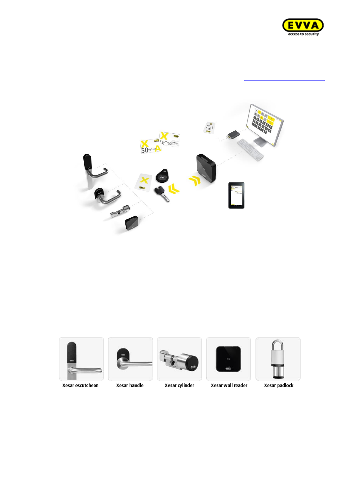
1.5 Condition of the identification medium .............................................................. 12
2 Hardware and installation ...................................................................................... 13
2.1 Xesar access components ................................................................................ 13
2.1.1 Xesar escutcheon ............................................................................... 14
2.1.2 Xesar handle ..................................................................................... 19
2.1.3 Xesar cylinder .................................................................................... 21
2.1.4 Xesar wall reader ............................................................................... 26
2.1.5 Xesar wall reader control unit .............................................................. 28
2.1.6 Xesar wall reader online control unit ..................................................... 28
2.1.7 Mains adapter for control unit .............................................................. 29
2.2 Installing Xesar access components .................................................................. 29
2.3 Xesar access components signal events ............................................................ 31
2.4 Xesar coding station ....................................................................................... 32
2.5 Xesar tablet ................................................................................................... 33
2.6 Xesar emergency power device ........................................................................ 35
2.7 Admin Card ................................................................................................... 36
2.8 Identification media ........................................................................................ 37
2.9 Construction Card (construction site medium) .................................................... 38
3 System requirements ............................................................................................ 39
3.1 Xesar 3.0 single-user system ........................................................................... 39
3.2 Xesar 3.0 multi-user system server .................................................................. 41
3.2.1 System requirements – Server ............................................................ 41
3.2.2 System requirements - Admin PC with coding station and Admin Card ...... 43
3.2.3 System requirements – client PC with coding station without Admin Card . 44
3.2.4 System requirements – client PC without coding station (PC/Tablet/Smartphone)
45
3.2.5 System requirements – Network (local network and Internet).................. 45
3.3 Attachment to the project checklist .................................................................. 47
3.3.1 Depiction of layout ............................................................................. 47
Page 3

3
KPM.X.Systemhandbuch_X3.0.EN.V1.9 | 05/2019 | Subjects to misprints and technical changes.
3.4 Service/communication ................................................................................... 48
3.5 Communication, Client PC - Server (backend) .................................................... 49
3.6 Communication, Online wall reader – Server (backend) ...................................... 49
4 System installations, upgrade and updates .............................................................. 50
4.1 Upgrade from Xesar 2.2 to Xesar 3.0 ................................................................ 50
4.1.1 Xesar upgrade compatibility ................................................................ 51
4.1.2 Upgrade instructions for Xesar 2.2 systems to Xesar 3.0 ......................... 51
4.2 Preparation of the PC for the Xesar 3.0 Installation ............................................ 53
4.2.1 Docker installation ............................................................................. 53
4.2.2 Coding station driverinstallation ........................................................... 58
5 Xesar 3.0 - Programs ............................................................................................ 65
5.1 Xesar Installation Manager .............................................................................. 67
5.2 AdminCard exchange: ..................................................................................... 82
5.3 Software Update ............................................................................................ 84
5.4 Periphery Manager: ........................................................................................ 90
5.5 Linking the coding station to the Xesar software ................................................ 95
5.6 Integrating your Xesar tablet into your system ................................................ 102
5.7 Manually uninstalling and installing the Xesar app (upgrade from Xesar 2.2 to Xesar
3.0) 107
6 Securing the Xesar system data with the Installation Manager ................................. 114
6.1 Manual backup ............................................................................................. 114
6.2 Automatic backup ........................................................................................ 116
6.3 Backup files ................................................................................................. 117
6.4 Restore ....................................................................................................... 118
7 Commissioning Xesar software ............................................................................. 123
7.1 General information on commissioning ............................................................ 123
7.2 Settings ...................................................................................................... 124
7.3 User groups: ............................................................................................... 128
7.4 User ........................................................................................................... 133
7.5 Calendars .................................................................................................... 136
7.6 Time profiles: .............................................................................................. 138
7.6.1 Office Mode add time profile ("permanent opening", applies to EVVA access
components) ............................................................................................... 140
7.6.2 Add time profile (for persons and identification media) ......................... 142
7.7 Access points ............................................................................................... 144
7.7.1 Add new access point: ...................................................................... 144
7.7.2 Describe access points: ..................................................................... 145
Page 4

4
KPM.X.Systemhandbuch_X3.0.EN.V1.9 | 05/2019 | Subjects to misprints and technical changes.
7.8 Zones: ........................................................................................................ 146
7.9 Authorisation profiles .................................................................................... 148
7.10 Persons ....................................................................................................... 151
7.10.1 Add person ...................................................................................... 153
7.11 Identification media ...................................................................................... 154
7.11.1 New identification medium ................................................................ 154
7.11.2 Existing identification medium ........................................................... 156
7.12 Adding a new EVVA access components .......................................................... 159
7.13 Commissioning the Xesar network adapter ...................................................... 159
7.13.1 PC configuration ............................................................................... 159
7.13.2 Commissioning a Xesar network adapter ............................................. 161
8 Xesar system management ................................................................................. 165
8.1 Starting and quitting Xesar ............................................................................ 165
8.2 The Xesar dashboard .................................................................................... 165
8.3 Xesar filter functions ..................................................................................... 167
8.3.1 Manual filter: ................................................................................... 167
8.3.2 Preset filter: .................................................................................... 167
8.3.3 Column view.................................................................................... 169
8.4 My profile .................................................................................................... 170
8.5 KeyCredits (units) ........................................................................................ 171
8.6 Support ...................................................................................................... 173
8.6.1 About Xesar .................................................................................... 173
8.6.2 Xesar help ....................................................................................... 174
8.6.3 Updates .......................................................................................... 174
8.6.4 Download support data ..................................................................... 174
8.7 Maintenance tasks ........................................................................................ 175
8.8 Firmware not up to date ................................................................................ 176
8.9 Battery warning ........................................................................................... 176
8.10 Coding stations ............................................................................................ 177
8.11 Online error ................................................................................................. 177
8.11.1 Insecure access points ...................................................................... 178
8.12 Identification media ...................................................................................... 178
8.12.1 Identification media – Bulk processing ................................................ 179
8.12.2 Revoke identification medium ............................................................ 180
8.12.3 Withdrawing authorisations from identification medium......................... 181
8.12.4 Blocking identification medium (adding them to the blacklist) ................ 181
8.12.5 Identification media that cannot be written to ...................................... 182
Page 5

5
KPM.X.Systemhandbuch_X3.0.EN.V1.9 | 05/2019 | Subjects to misprints and technical changes.
8.12.6 Insecure identification media ............................................................. 183
8.12.7 Identification media not up to date ..................................................... 183
8.12.8 Releases with disabled identification media ......................................... 183
8.13 Event logs ................................................................................................... 184
8.13.1 Event log ........................................................................................ 184
8.13.2 System event log ............................................................................. 185
8.14 Xesar tablet (programming unit) .................................................................... 186
8.14.1 Xesar tablet app............................................................................... 186
8.15 Xesar virtual network (XVN) .......................................................................... 191
8.15.1 Transferring access events using identification media ........................... 192
8.15.2 Transferring blacklist entries using identification media ......................... 192
8.15.3 Transferring "Unlocking attempt by medium" notifications ..................... 193
8.15.4 Transferring the information "Identification medium deleted from door component"
193
8.15.5 Transferring the battery status using identification media ...................... 194
8.16 Replacing AdminCard: .................................................................................. 194
8.17 Revoking the process of adding a component ................................................... 196
8.18 Removing components (resetting to construction mode) ................................... 197
8.19 Force component removal (component faulty) ................................................. 198
8.20 Online wall reader ........................................................................................ 198
8.21 Potential errors ............................................................................................ 200
8.21.1 Display certificate warning (this is not an error) ................................... 200
8.21.2 Docker does not start automatically (autostart) ................................... 200
8.21.3 Update to Xesar 3.0 ......................................................................... 200
8.21.4 Number of zones in Xesar 3.0 (compared with Xesar 2.2) ..................... 200
8.21.5 Import from Xesar 2.2 (time zone) ..................................................... 200
8.21.6 Calendar import ............................................................................... 200
8.21.7 COM port configuration errors in Windows 10 ...................................... 200
8.21.8 Expired certificates (Xesar tablet, browser) ......................................... 201
8.21.9 Unable to start docker ...................................................................... 201
8.21.10 Xesar Lifetime in Xesar 2.2 ............................................................. 201
8.21.11 Blocking the firewall / preventing the import .................................... 201
8.21.12 Identification media read error ....................................................... 201
8.21.13 Xesar tablet error (ARES FX716M) ................................................... 202
8.21.14 XVN time delay ............................................................................. 202
8.21.15 Tablet error display XTDE17 ........................................................... 202
8.21.16 Installation Manager no longer recognises a coding station ................. 202
Page 6

6
KPM.X.Systemhandbuch_X3.0.EN.V1.9 | 05/2019 | Subjects to misprints and technical changes.
8.21.17 No dashboard display in the browser ............................................... 202
8.21.18 Blue screen after removing a medium from the coding station ............ 202
8.21.19 Problems detecting media with Windows 10 Pro x64 Version build 1709202
8.21.20 Tablet synchronisation ................................................................... 202
8.21.21 Tablet synchronisation ................................................................... 202
8.21.22 Deactivate the "Certificate Propagation Service" ............................... 203
8.21.23 A server must not go into standby mode. ......................................... 203
8.21.24 A CU with 2 wall readers ................................................................ 203
8.21.25 Disable identification media ............................................................ 203
9 Table of figures .................................................................................................. 204
Page 7

7
KPM.X.Systemhandbuch_X3.0.EN.V1.9 | 05/2019 | Subjects to misprints and technical changes.
1 General information and system over-
view
This Xesar system manual describes how to operate the Xesar software and any associated Xesar
system components.
The products and/or systems described in the Xesar system manual must exclusively be operated
by persons that have been adequately qualified for the corresponding task. Qualified personnel is
able to identify risks when handling products/systems and prevent potential hazards on the basis
of their expertise.
1.1 General legal notes
EVVA concludes the contract on the use of Xesar exclusively on the basis of its General Terms of
Business (EVVA-GTB) as well as its General Licensing Conditions (EVVA-ALB) with regards to the
software for the product. Please refer to http://www.evva.com/terms.
We explicitly notify clients that the use of the locking system subject to this contract may trigger
legal approval, reporting or registration obligations, in particular with regard to data protection
(e.g. if you are establishing a comprehensive information system), as well as grant the right of codetermination to staff in the event of use on corporate premises. Customers, clients and end users
shall be responsible for product use in compliance with legal stipulations.
The aforementioned information must be observed and passed on to operators and users as per
the defined manufacturer product liability according to product liability legislation. Non-compliance
releases EVVA from any liability.
Any use deemed as non-compliant with the contract or as unintended use as well as any repair
work or modifications that have not been explicitly approved by EVVA and all types of incorrect
servicing may cause malfunctions and are prohibited. Any modifications that have not been explicitly approved by EVVA render claims to liability, warranty as well as any separate guarantee claims
void.
Architects and advisory institutions are obliged to request all necessary product information from
EVVA and take into account all such information to comply with obligations regarding information
and instructions under the Product Liability Act. Specialist retailers and installers must comply with
the information in EVVA documentation and they must pass on such information to customers, if
applicable.
Please refer to the Xesar product catalogue for additional information beyond these vital instructions. These are available at http://www.evva.com/xesarhttp://www.evva.com/xesar
Page 8
8
KPM.X.Systemhandbuch_X3.0.EN.V1.9 | 05/2019 | Subjects to misprints and technical changes.
1.2 Imprint
2nd English Edition, 05/2019
This edition shall not longer be valid upon publication of a new system manual.
All rights reserved. This system manual must not be reproduced, copied or adapted neither in full
or in part using electronic, mechanical or chemical methods or any other procedures without written
consent by the publisher.
We shall not assume any liability for technical or printing errors and their potential consequences.
However, the data in this system manual is revised regularly and corrections are incorporated.
All trademarks and industrial property rights reserved. We reserve the rights to make adaptations
and update the document without prior notification.
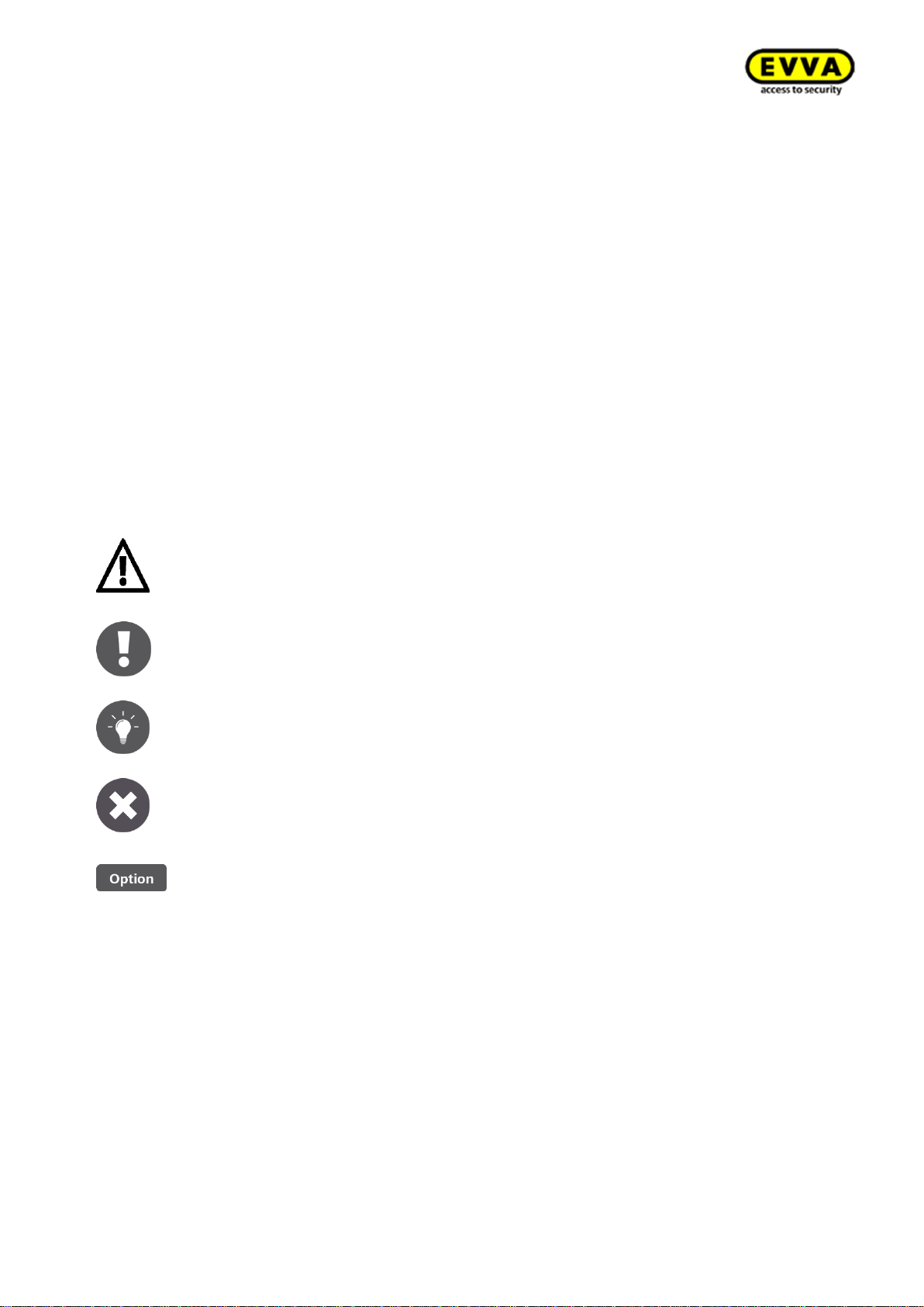
1.3 Explanation of symbols
The following signs and symbols are used in the system manual to facilitate illustration:
Attention, risk of material damage in the event of non-compliance
with the corresponding safety measures.
Notices and additional information
Hints and recommendations
Error messages
Options
Page 9
9
KPM.X.Systemhandbuch_X3.0.EN.V1.9 | 05/2019 | Subjects to misprints and technical changes.
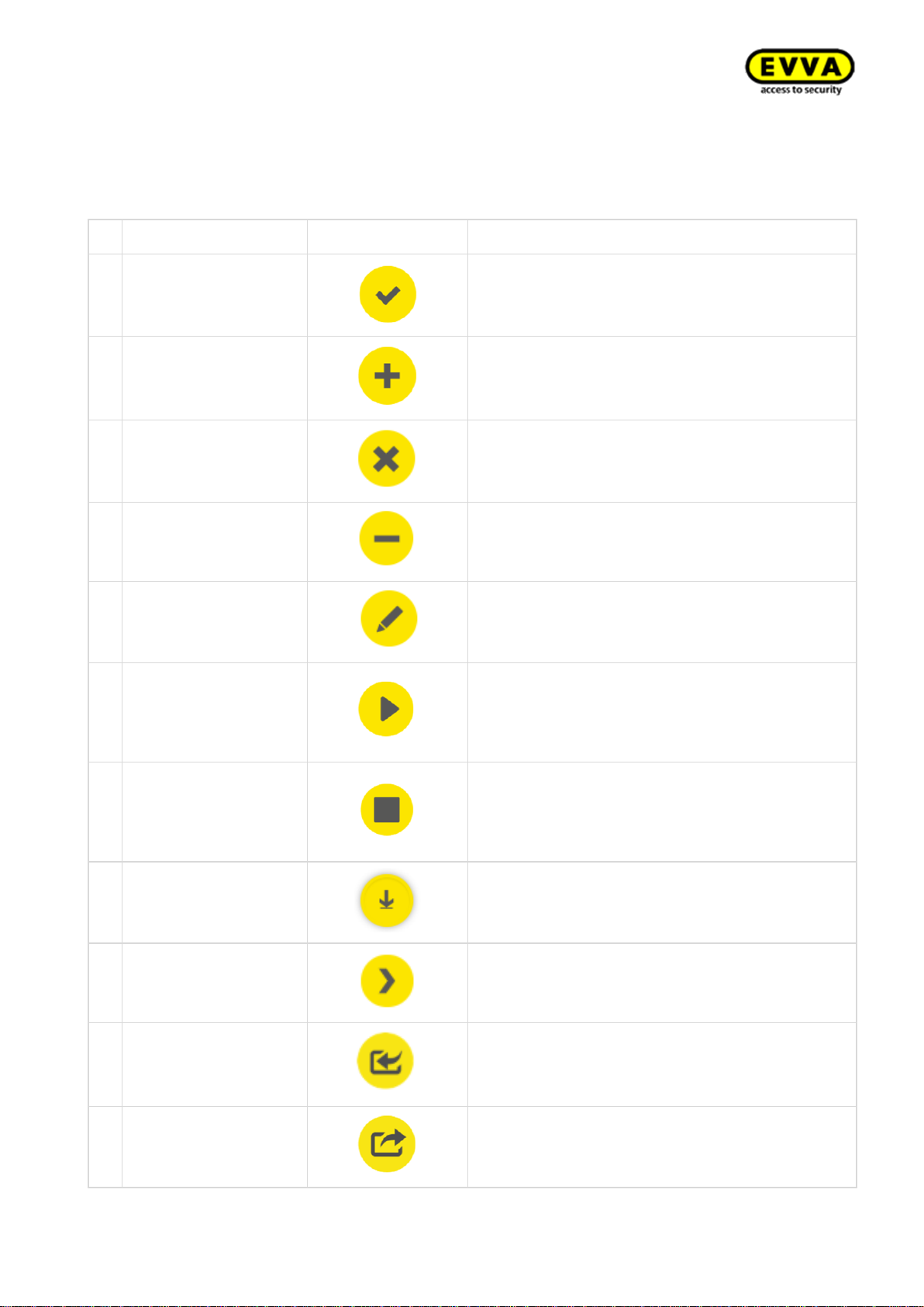
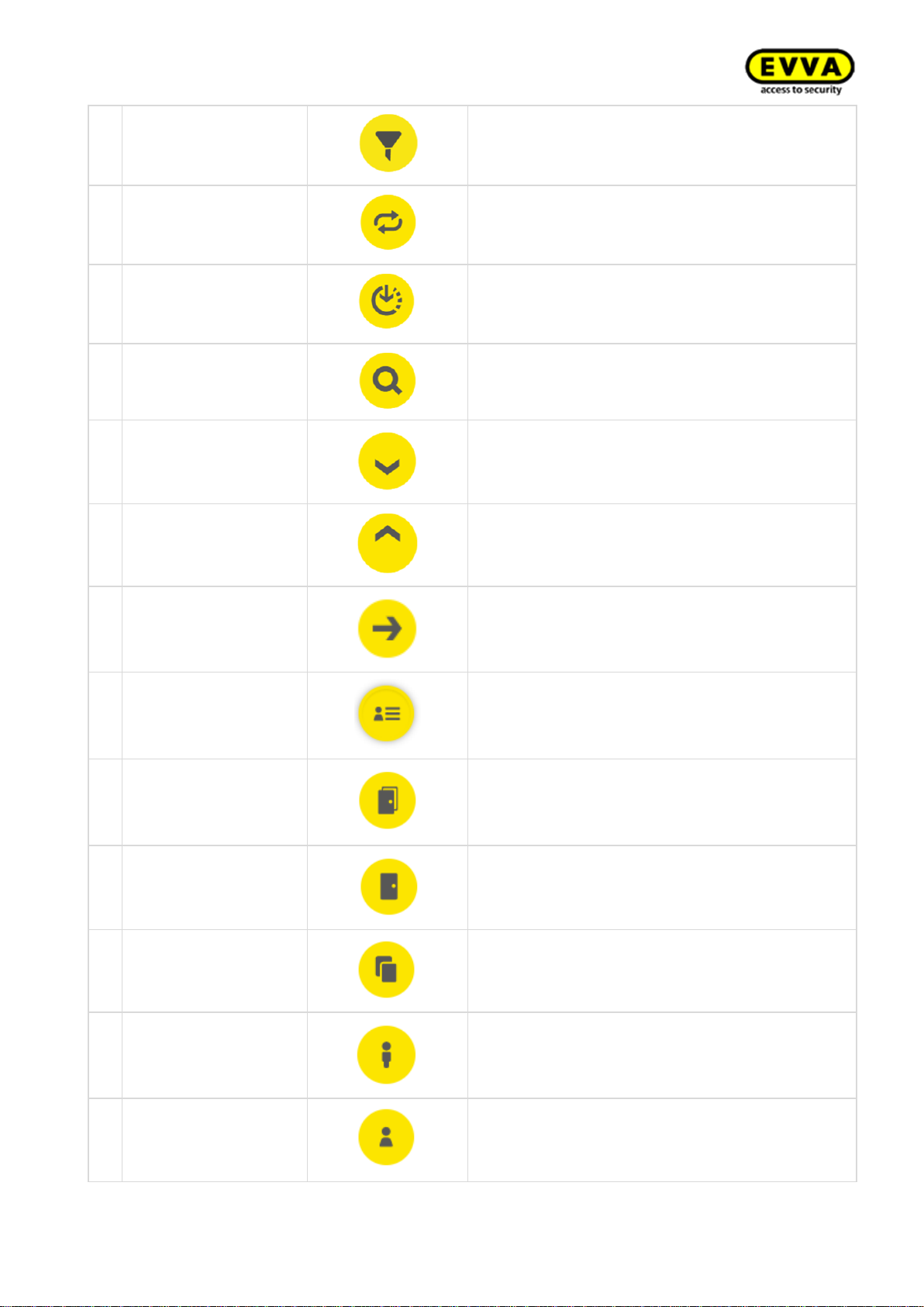
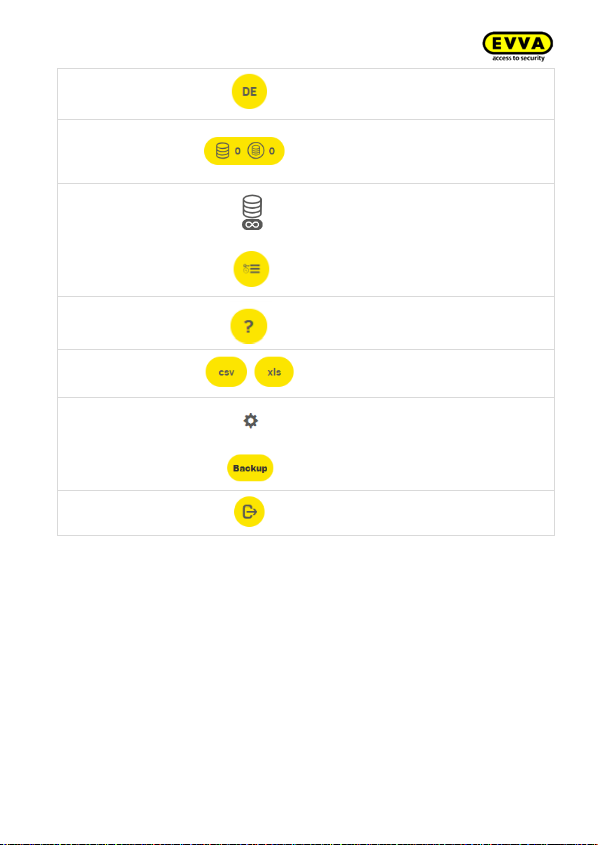
1.4 Signs and symbols within the Xesar software
The following icons and symbols are used within the Xesar software, Xesar Installation Manager
and Periphery Manager:
#
Condition
Visualisation
Explanation
1
Confirm/save
Confirming or saving input
2
Add
Adding elements, e.g. new persons, installation
location, etc.
3
Discard entries
Discarding an entry
4
Remove
Deleting elements from the Xesar system, e.g.
time profile, installation location, etc.
5
Edit
Editing the system (Installation Manager)
6
Start application
Starting the system (Xesar Installation Manager)
or starting the connection between coding station and Xesar software (Xesar Periphery Manager)
7
Stop application
Stopping the system (Xesar Installation Manager) or stopping the connection between coding
station and Xesar software (Xesar Periphery
Manager)
8
Download
For example, download Xesar tablet app or Xesar
Periphery Manager
9
Continue
Continuing to next input
10
Load/transfer
Loading the AdminCard
11
Export
Exporting lists (persons, events, etc.)
Page 10
10
KPM.X.Systemhandbuch_X3.0.EN.V1.9 | 05/2019 | Subjects to misprints and technical changes.
12
Filter
Find potential filter settings here
13
Update/connect
On Xesar dashboard runs an activity at the
backend.
In Xesar tablet app: connect to a connected door
14
Not updated/waiting
for update/download
update
An update is available and can be downloaded
using this icon
15
Search
Search for a specific event entry here
16
Maximise
Maximises the view
17
Minimise
Minimises the view
18
Go to
Click here to go to the Xesar management software The required browser window opens
19
System event log
Shows actions carried out within the Xesar software by users and the system
20
Filtered by zones
Shows all zones to which a person has an access
authorisation
21
Filtered by access
points
Shows all locations to which a person has an access authorisation
22
Filtered by identification media
Shows all identification medium assigned to a
person
23
Filtered by persons
Filter by persons
24
My profile
Add a description here and change the personal
password
Page 11
11
KPM.X.Systemhandbuch_X3.0.EN.V1.9 | 05/2019 | Subjects to misprints and technical changes.
25
Displayed language
Change the language here.
26
Show KeyCredit units
Shows the number of KeyCredits to be deducted
(e.g. as a result of changing authorisations or issuing new identification media).
Also shows the number of added KeyCredits
27
Show Xesar Lifetime
KeyCredits
This icon is displayed if Xesar Lifetime KeyCredits have been activated.
28
Event log
For instance, this icon appears below persons.
Filters all of a person's access events
29
Help information
This symbol enables the display of help texts.
30
Lists export
The displayed list can be exported as CSV or
XLS file.
31
List view settings
Adjustment of list view regarding column selection, number of lines per page, save settings and
reset
32
Backup button
Click on the backup button in the Installation
Manager to create a backup of the system data
33
Logout
Click on Logout button to end the session.
Page 12
12
KPM.X.Systemhandbuch_X3.0.EN.V1.9 | 05/2019 | Subjects to misprints and technical changes.
1.5 Condition of the identification medium
No.
Status
Visuali-
sation
Explanation
1
Insecure disabled identification
medium
There are still insecure access points.
2
Secure disabled identification medium
There are no uncertain access points.
3
Unauthorised identification medium
The identification medium is not authorised.
4
Currently valid
5
Currently invalid
6
Currently valid identification me-
dium, becomes invalid upon up-
date
7
Currently invalid identification medium, becomes valid identification
medium when updated
8
Currently invalid identification medium, with a validity period that
lies in the future.
9
Deactivated identification medium
The medium has been deactivated, there are
no further insecure access points and the calendar is no longer important.
Page 13
13
KPM.X.Systemhandbuch_X3.0.EN.V1.9 | 05/2019 | Subjects to misprints and technical changes.
2 Hardware and installation
Please check carefully to make sure the Xesar product you selected is suitable for your application.
We have made the required data sheet available on our homepage: https://www.evva.com/uk-
en/products/electroniclockingsystemsaccesscontrolsystems/xesar/
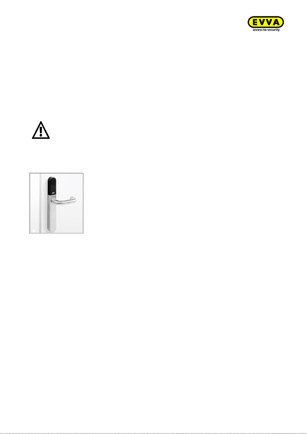
Figure 1: System architecture (sample image)
2.1 Xesar access components
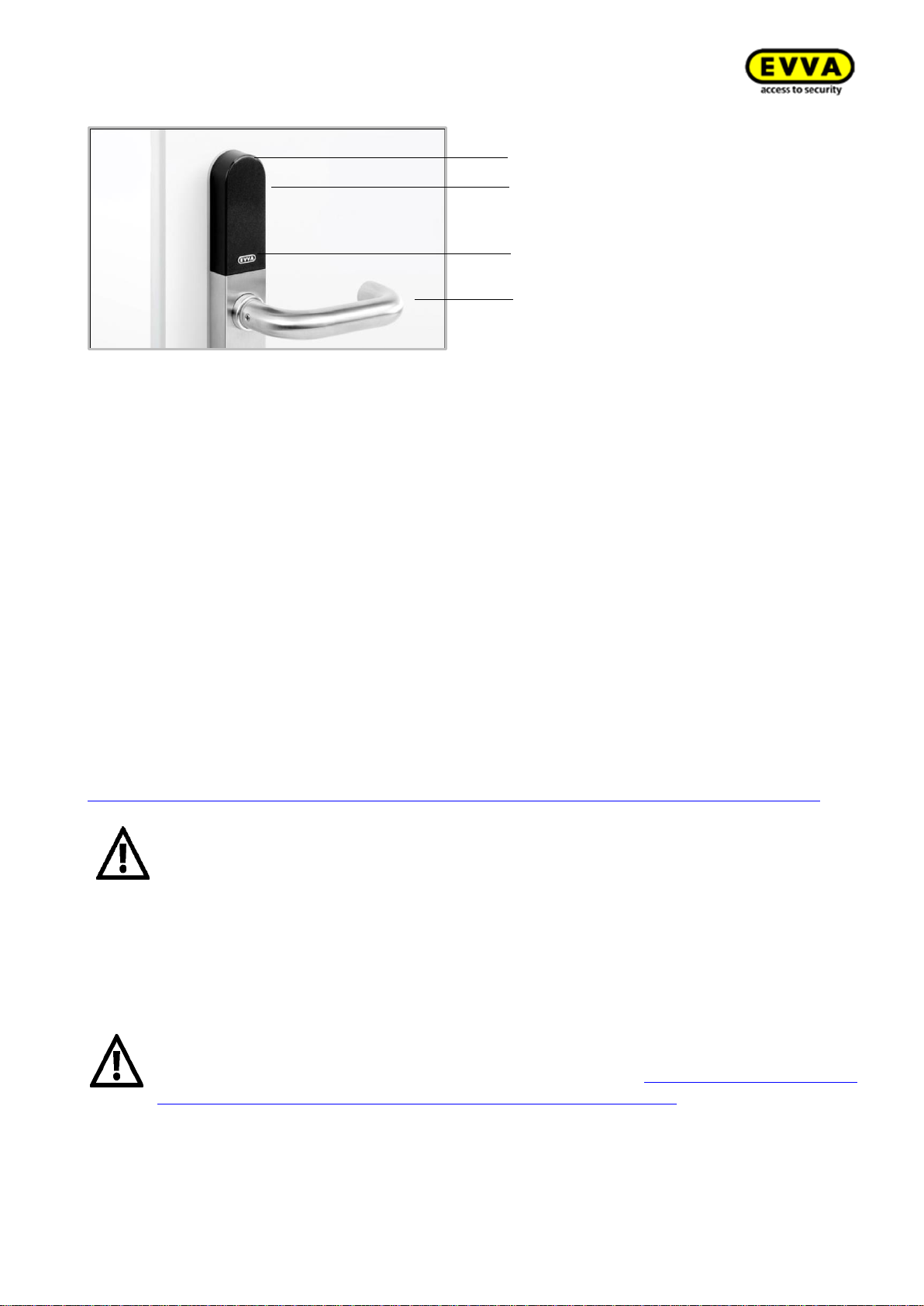
Xesar's versatility offers different components, such as different escutcheon, handle, cylinder
shapes (including hybrid and cam locks), wall readers and padlocks.
Figure 2: Xesar access components (sample image)
Page 14
14
KPM.X.Systemhandbuch_X3.0.EN.V1.9 | 05/2019 | Subjects to misprints and technical changes.
Xesar access component interface
All Xesar access components feature a plug-interface to update components via a tablet. The interface may also be used as an emergency power supply for battery-operated Xesar access components.
The interface is located on the front of all Xesar access components, behind the connector cover
(EVVA logo). Slightly press towards the inside on the left-hand side of the EVVA logo (near the "E")
with your finger and fold out on the right-hand side (near the "A") to access the interface.
After having used the interface, once again carefully close the connector cover (EVVA logo) to
protect the Xesar access components from penetrating dust and humidity.
Do not use pointed objects to open and close the cover to prevent potential
damage.
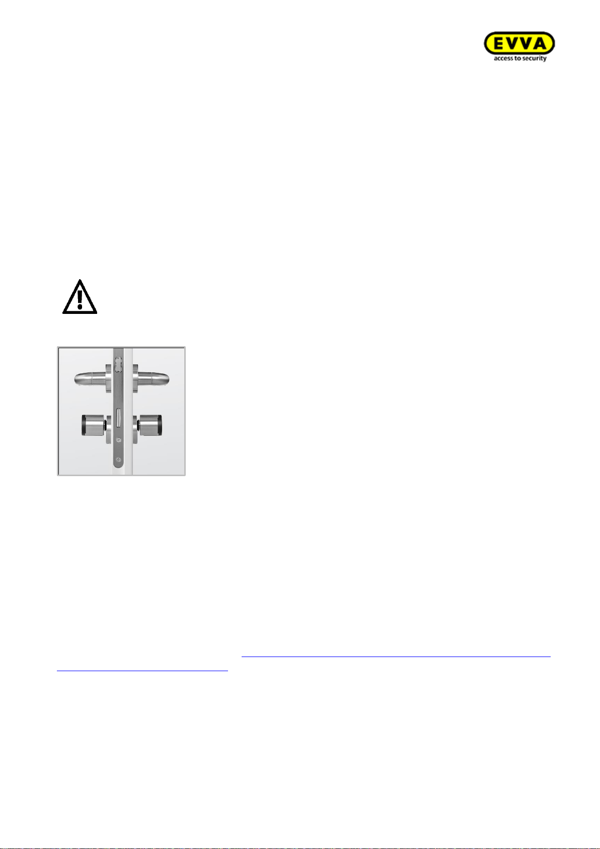
2.1.1 Xesar escutcheon
Figure 3: Xesar escutcheon (sample image)
The Xesar escutcheon is a battery-operated access component suitable for indoor and outdoor use.
The Xesar escutcheon is suitable for conventional metal frames and solid door locks with a handle
angle of up to 40°, for self-locking escape door locks as per EN 179/EN 1125, fire protection doors
and there are also versions available for panic and emergency exit doors with bar handles or push
handles as per EN 1125.
Please use the dedicated seal enclosed with the product in the event of a use outdoors or in zones
that are exposed to water.
Please check carefully to make sure the Xesar product you selected is suitable for your application.
Page 15
15
KPM.X.Systemhandbuch_X3.0.EN.V1.9 | 05/2019 | Subjects to misprints and technical changes.
2.1.1.1 Xesar escutcheon — functional description
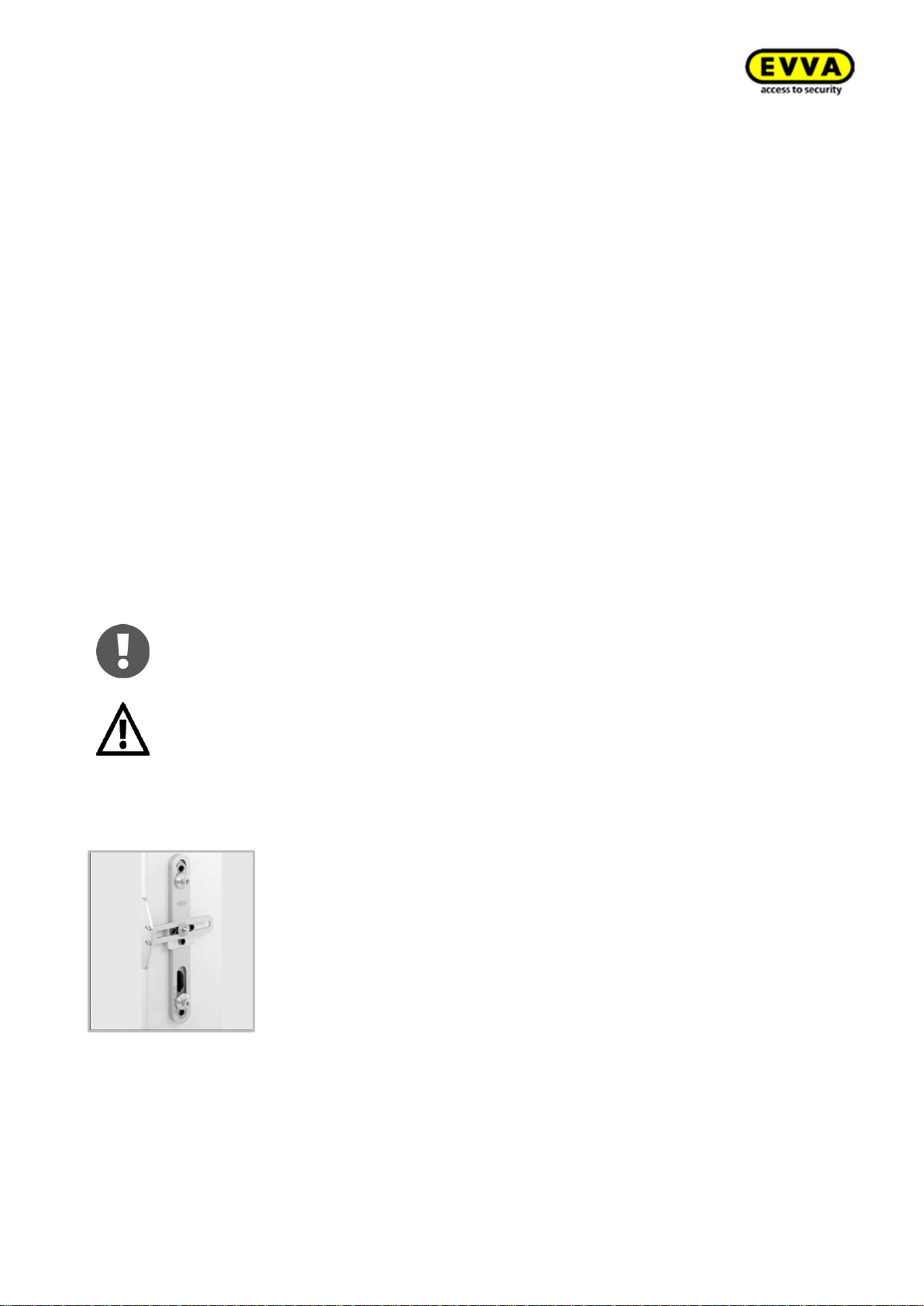
Figure 4: Xesar escutcheon (sample image)
Reader unit
The reader unit sensor is located on the outside of the Xesar escutcheon between the connector
(EVVA logo) and visual indicator (LED).
Functional principle
The outside handle is disengaged by default – operating the outside handle will not change the
position of the latch. Hold an authorised identification medium to the reader unit, the outside handle
is mechatronically engage for five seconds. If you operate the outside handle during this period,
the latch or bolt (depending on the lock type) will move.
The inside handle is always engaged and can be operated at any time. In this process, the mechanism always unlocks the latch.
Xesar escutcheons feature an event memory for the last 1,000 events. Once the event memory is
full, the system overwrites the oldest entries with the most recent events. For this reason, it is
important to regularly synchronise events to prevent event records from being lost.
Please refer to the corresponding data sheet for additional specifications at:
https://www.evva.com/uk-en/products/electroniclockingsystemsaccesscontrolsystems/xesar/
Please note the continuous release function (see section:
Identification media ) and the different acoustic and visual signals
(Section:2.3Xesar access components signal events).
Please note that if access components are installed in fire doors, the certificates are exclusively valid in conjunction with approvals from the corresponding door manufacturer.
Please also note the following, important notices before use!
Important notes on use, general legal information, danger to life and limb, risk of
explosion, climatic and environmental effects, installation instructions and use
of batteries; please refer to our safety instructions on operation and cleaning
which are included and can be found on our website at: https://www.evva.com/uk-
en/products/electroniclockingsystemsaccesscontrolsystems/xesar/
Visual signals
Reader unit
Connection cable
Handle
Page 16
16
KPM.X.Systemhandbuch_X3.0.EN.V1.9 | 05/2019 | Subjects to misprints and technical changes.
Battery replacement
We recommend having batteries replaced by trained, specialist personnel only.
Replace batteries in due time, as soon as the escutcheon indicates "Battery low", see section: In-
stalling Xesar access components
Please note that specialist personnel must install Xesar access components as per the notes and
information as well as the assembly manual enclosed with the product.
EVVA provides a host of different installation tools to make installing your Xesar system easier.
Visit our website.
Language-neutral assembly manual
To support Xesar access component assembly EVVA provides language-neutral assembly which
can be found on the packaging of the corresponding product or on our homepage.
https://www.evva.com/uk-en/products/electroniclockingsystemsaccesscontrolsystems/xesar/
Product-specific assembly video clips
We have provided assembly video clips with demonstrations of complex assembly steps here:
http://video.evva.com/tutorials/xesar/exdrz1/exdrz1-1/ domainhttp://video.evva.com/tutorials/xesar/exdrz1/exdrz1-1/
Language-neutral drilling template
EVVA provides a single-use, cardboard drilling template without text to support the assembly of
versions requiring one or several drilled holes. They are printed on the corresponding product
packaging and are available in our homepage in the general download section:
https://www.evva.com/uk-en/products/electroniclockingsystemsaccesscontrolsystems/xesar/
The assembly manuals and the packaging feature QR codes which will take
you directly to the corresponding video sequence or assembly manual.
You must observe the listed sequence of installation steps as otherwise malfunctions may occur.
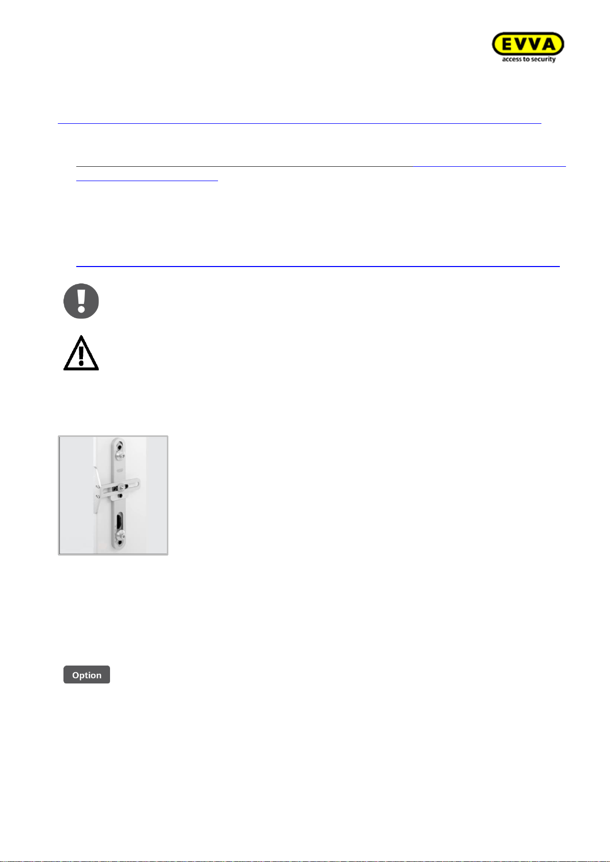
Installation using drilling template
Figure 17: Drilling template (sample image)
EVVA provides a high-quality, metal drilling template to facilitate preparing the door for an assembly of any type of Xesar escutcheons and Xesar handles.
An adjustable stop safeguards that holes are correctly aligned and it enables adaptations of the
settings to match the requirements of any door situation. Hardened metal drilling sleeves guarantee a long service life even after intense use.
Page 17

17
KPM.X.Systemhandbuch_X3.0.EN.V1.9 | 05/2019 | Subjects to misprints and technical changes.
The drilling template is optionally available.
Product code: E.ZU.BE.BS.V1
Page 18
18
KPM.X.Systemhandbuch_X3.0.EN.V1.9 | 05/2019 | Subjects to misprints and technical changes.
Xesar access components signal events.
Repeatedly disregarding the "Battery low" warning may cause escutcheon malfunctions.
At normal ambient temperatures, the first "Battery low" warning indicates that up to 1,000 actuations are still possible within the next 4 weeks. Temperatures deviating from normal ambient temperatures may cause the escutcheon to prematurely fail.
Do not use rechargeable batteries. Please ask your specialist retailer for a list of recommended
battery models.
Always replace all batteries used (three AAA batteries) in the corresponding escutcheon! If applicable, you may be required to synchronise the system time using the Xesar tablet after having
replaced the batteries.
If the batteries are drained, it is exclusively possible to operate the escutcheon using the
emergency power device (optional accessory) and a MasterKey medium.
Battery replacement procedure
1. The battery compartment is located in the top of the internal escutcheon plate. You require
a T8 Torx screwdriver to open the battery compartment. Undo the screw on the bottom of
the escutcheon.
2. Turn the Torx screw clockwise until you can remove the internal escutcheon plate.
3. Hold the bottom of the internal escutcheon plate and carefully remove it from the attach-
ment panel. You can now pull the internal escutcheon plate over the handle. Make sure you
do not scratch the handle in the process. You can alternatively remove the internal handle
beforehand.
4. Now remove the three empty AAA batteries and replace them with new batteries you ac-
quired earlier. Ensure correct polarity when inserting batteries.
The component outputs a signal to confirm having correctly completed the battery replacement
(signal 8 in the signal table in section: 2.3 Xesar access components signal events
Now once again position the internal escutcheon plate on the attachment plate and proceed in
reverse order to reassemble the internal escutcheon plate.
Battery replacements or power cuts must not exceed a duration of one minute
as otherwise the escutcheon must be resynchronised using the Xesar tablet.
The procedure to replace batteries in Xesar escutcheons for panic doors is
identical despite the different internal escutcheon plate's design.
If the batteries are drained, it is exclusively possible to operate the escutcheon using the emergency power device (optional accessory) and a Mas-
terKey medium.
Page 19
19
KPM.X.Systemhandbuch_X3.0.EN.V1.9 | 05/2019 | Subjects to misprints and technical changes.
2.1.2 Xesar handle
Figure 5: Xesar handle (sample image)
The Xesar handle is a battery-operated access component suitable for internal solid or glass doors
in conjunction with a corresponding glass door lock.
Thanks to compliance with fundamental lock standards and a handle angle of up to 40° the Xesar
handle is compatible with many European lock types.
The Xesar handle is suitable for conventional solid door locks with a handle angle of up to 40°, selflocking escape door locks as per EN 179 and fire protection doors.
Please check carefully to make sure the Xesar product you selected is suitable for your application.
We have made the required data sheet available in the download section of our homepage:
https://www.evva.com/uk-en/products/electroniclockingsystemsaccesscontrolsystems/xesar/
2.1.2.1 Xesar handle — functional description
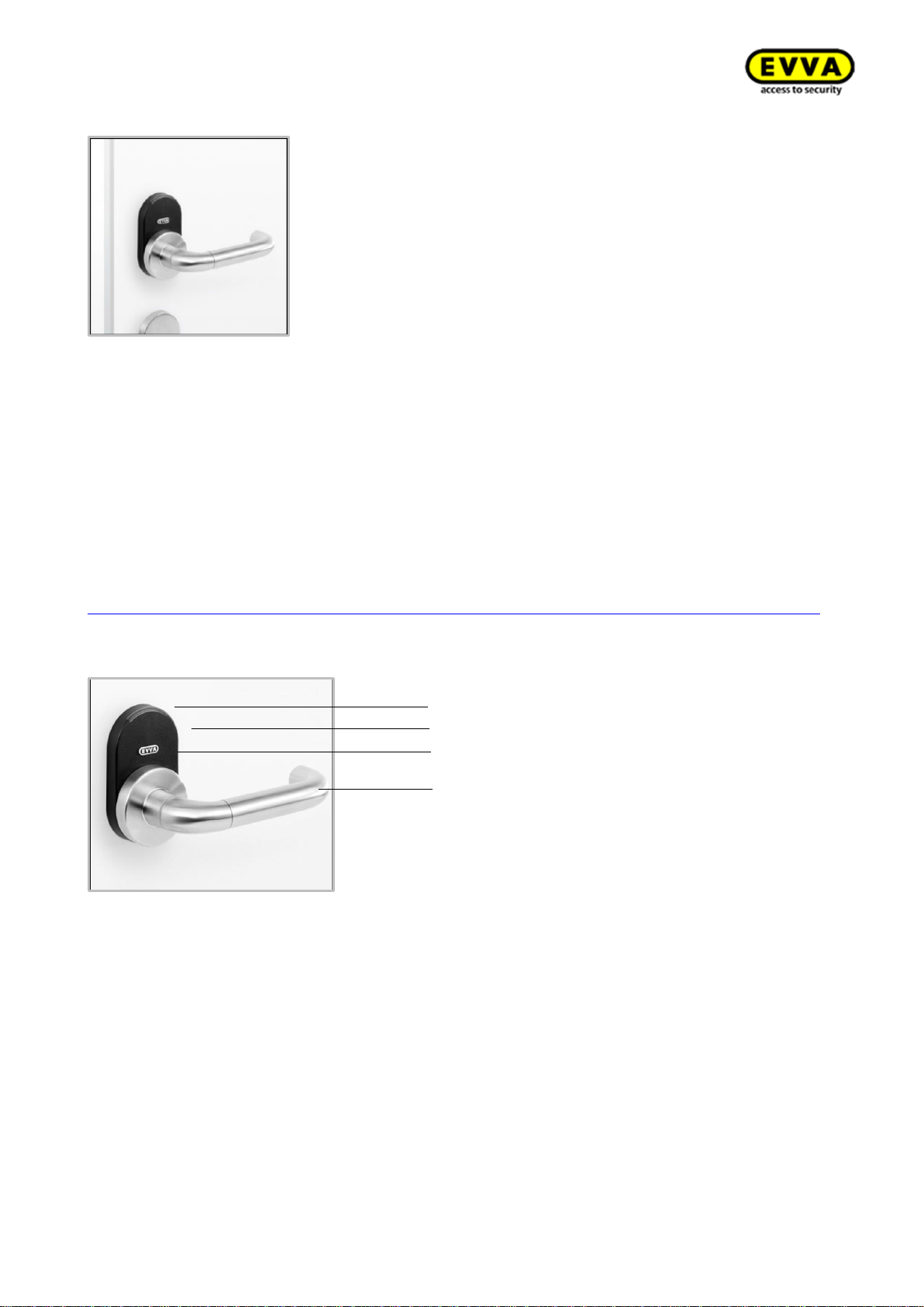
Figure 6: Xesar handle (sample image)
Visual and audible signalling
Xesar handles audibly and visually indicate events. For this purpose, there is an LED on the upper
edge of the reader unit of Xesar handles. For a list of all signals please refer to section:2.3 Xesar
access components signal events
Visual signals
Reader unit
Connection cable
Handle with battery
compartment
Page 20
20
KPM.X.Systemhandbuch_X3.0.EN.V1.9 | 05/2019 | Subjects to misprints and technical changes.
Reader unit
The reader unit sensor is located on the outside of the Xesar handle between the connector (EVVA
logo) and the LED.
Functional principle
The outside handle is disengaged by default – operating the outside handle will not change the
position of the latch. Hold an authorised identification medium to the reader unit to mechatronically
engage the outside handle for five seconds. If you operate the outside handle during this period,
the latch or bolt (depending on the lock type) will move.
The inside handle is always engaged and can be operated at any time. In this process, the mechanism always unlocks the latch.
Xesar handles feature an event memory for the last 1,000 events. Once the event memory is full,
the system overwrites the oldest entries with the most recent events. For this reason, it is important
to regularly synchronise events to prevent event records from being lost.
Please refer to the corresponding data sheet for additional specifications at:
https://www.evva.com/uk-en/products/electroniclockingsystemsaccesscontrolsystems/xesar/
Please note the permanent release function (see section: 0
Identification media ) and the different acoustic and visual signals (see section: 2.3 Xesar access components signal events).
Please note that if access components are installed in fire doors, the certificates are exclusively valid in conjunction with approvals from the corresponding door manufacturer.
Please also note the following, important notices before use!
Important notes on use, general legal information, danger to life and limb, risk of explo-
sion, climatic and environmental effects, installation instructions and use of bat-
teries; please refer to our safety instructions on operation and cleaning which are
included and can be found on our website at: https://www.evva.com/uk-en/prod-
ucts/electroniclockingsystemsaccesscontrolsystems/xesar/
Battery replacement
We recommend having batteries replaced by trained, specialist personnel only.
Replace batteries in due time, as soon as the handle indicates "Battery low", see section: 2.3 Xesar
access components signal events
Repeatedly disregarding the "Battery low" warning may cause
handle malfunctions.
At normal ambient temperatures, the first "Battery low" warning indicates that up to 1,000 actuations are still possible within the next 4 weeks. Temperatures deviating from normal ambient temperatures may cause the handle to prematurely fail.
Do not use rechargeable batteries. Please ask your specialist retailer for a list of recommended
battery models. If the batteries have been drained, it is exclusively possible to operate the handle
using the emergency power device (optional accessory).
Page 21
21
KPM.X.Systemhandbuch_X3.0.EN.V1.9 | 05/2019 | Subjects to misprints and technical changes.
Battery replacement procedure
1. The battery compartment is located in the outside handle of the Xesar handle. You require
one type CR123A battery (please ask you retailer for a list of recommended battery models)
and the following tools to open the battery compartment: Allen key, 2.5.
2. If you would like to remove the handle tube of the outside handle, use the Allen key and
turn the attachment screw clockwise until you can remove the handle tube.
3. Make sure you only screw in the attachment screw as far as absolutely necessary.
4. Now remove the empty battery and replace it with a new battery you acquired earlier. En-
sure correct polarity when inserting the battery.
5. Once again position the handle tube on the outside handle and fasten it in reverse sequence.
The component outputs a signal to confirm having correctly completed the battery
replacement (signal 8 in the signal table from section: 2.3 Xesar access components signal events
).
Battery replacements or power cuts must not exceed a duration of one minute
as otherwise the Xesar handle must be resynchronised using the Xesar tablet.
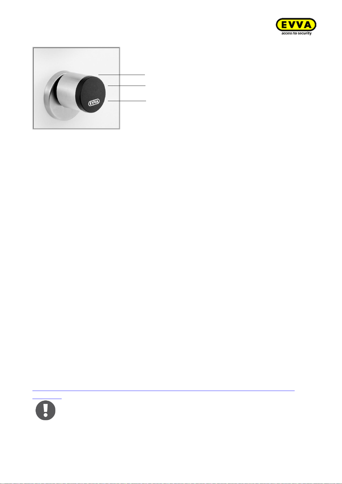
2.1.3 Xesar cylinder
Figure 7: Xesar cylinder (sample image)
Xesar cylinders are battery-operated access components.
The standard Xesar cylinder variant already comes with a host of anti-manipulation protection
measures. Please refer to the product catalogue for more information.
Xesar cylinders are suitable for indoors and outdoors as well as fire and emergency exit doors.
Xesar cylinders are available as half cylinders or double cylinders with one-sided or double-sided,
electronic access.
Please carefully check the Xesar cylinder you selected is suitable for your application.
Please refer to the corresponding data sheet for additional specifications at:
https://www.evva.com/at-de/xesar/https://www.evva.com/uk-en/products/electroniclockingsys-
temsaccesscontrolsystems/xesar/
Page 22
22
KPM.X.Systemhandbuch_X3.0.EN.V1.9 | 05/2019 | Subjects to misprints and technical changes.
2.1.3.1 Xesar cylinder — functional description
Figure 8: Xesar thumb turn (sample image)
Visual and audible signalling
Xesar cylinders audibly and visually indicate events. For this purpose, there is an LED on the edge
of the reader unit on Xesar cylinders. For a list of all available signals please refer to section: 2.3
Xesar access components signal events
Reader unit
The reader unit sensor is located in the plastic cap of the Xesar cylinder thumb turn between the
EVVA logo and the LED.
Functional principle
By default, the electronic outside thumb turn of the Xesar cylinder is disengaged. The cam remains
disengaged upon operating the outside thumb turn and the outside thumb turn turns without engaging with the cam.
Hold an authorised identification medium to the Xesae cylinder's reader unit to mechatronically
engage the outside thumb turn for five seconds, so that the cam of the Xesar cylinder engages
when operating the outside thumb turn.
The purely mechanically operated inside parts of the versions with one-sided electronic authorisation always remains engaged with Xesar cylinders and can be operated at any time.
On Xesar cylinders with double-sided electronic authorisation, the operation of the inside thumb
turn is identical to the electronic outside thumb turn.
Xesar cylinders feature an event memory for the last 1,000 events. Once the event memory is full,
the system overwrites the oldest entries with the most recent events. For this reason, it is important
to regularly synchronise events to prevent event records from being lost.
Please refer to the corresponding data sheet for additional specifications at:
https://www.evva.com/uk-en/products/electroniclockingsystemsaccesscontrolsystems/xesar/#tab6
Due to technical reasons, the FZG and FAP versions do not feature a rotation
brake!
Please note the continuous release function (see section:
Visual signals
Reader unit
Connection cable
Page 23
23
KPM.X.Systemhandbuch_X3.0.EN.V1.9 | 05/2019 | Subjects to misprints and technical changes.
Identification media ) and the different acoustic and visual signals (section:
2.3 Xesar access components signal events).
Xesar cylinders feature a rotary damper as standard. Ensure it is installed in
its correct position (see assembly manual) as malfunctions would otherwise
occur during on-going operation. Malfunctions in unapproved installation positions do not represent product faults and are consequently not deemed as
a valid reason for complaints.
Please also note the following, important notices before use!
Important notes on use, general legal information, danger to life and limb,
risk of explosion, climatic and environmental effects, installation instruc-
tions and use of batteries; please refer to our safety instructions on op-
eration and cleaning which are included and can be found on our website at:
https://www.evva.com/uk-en/products/electroniclockingsystemsaccesscontrolsystems/xesar/#tab6
Depending on the cylinder's protrusion beyond the escutcheon or any installed cylinder rosettes, the Xesar thumb turn may be hard to operate as a
result of friction caused by the seal on the escutcheon or rosette of the cylinder. There is the option to remove said seals when installing the assembly
indoors.
Xesar cylinders with European profiles are equipped with a service bore at
the front of the electronics module. Use it to secure the thumb turn axis with
a matching metal pin and facilitate disassembly of the cylinder thumb turn.
The metal pin must have a minimum diameter of 2 mm and be at minimum
40 mm long.
Procedure:
Step 1:
Insert a matching metal pin (e.g. a
2 mm Allen key) into the front service duct of your European profile
cylinder.
Step 2:
In this process, turn the thumb turn until you are able to insert the
metal pin considerably deeper into the service duct. Now hold the
metal pin in this position and disassemble the thumb turn as usual
using the assembly tool.
Step 3:
Once again carefully remove the metal pin after having removed the
thumb turn.
Page 24
24
KPM.X.Systemhandbuch_X3.0.EN.V1.9 | 05/2019 | Subjects to misprints and technical changes.
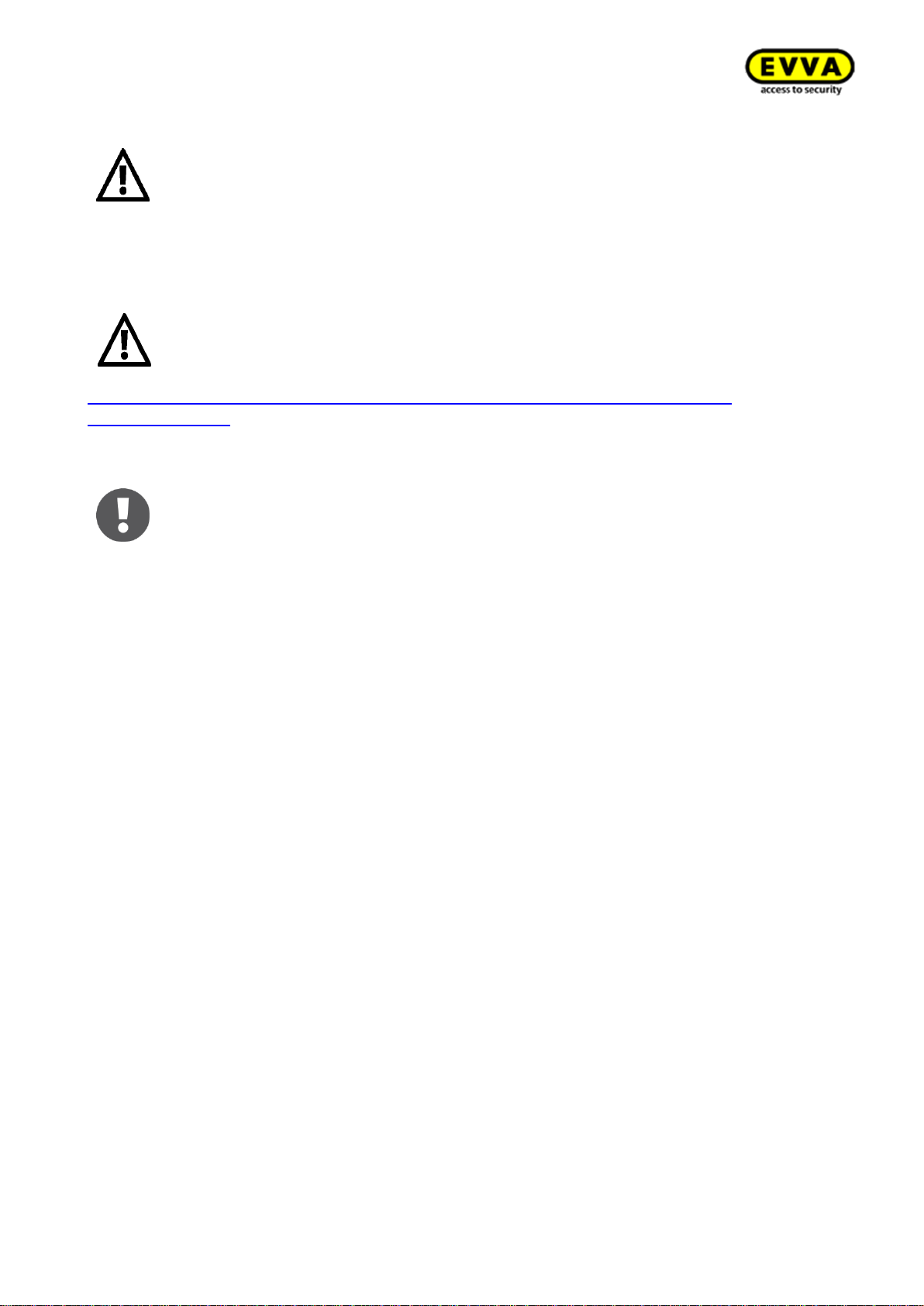
2.1.3.2 Xesar padlock
Figure 9: Xesar cylinder (sample image)
Xesar padlocks are battery-operated access components.
The HM24-S Xesar padlock with hardened steel shackle is suitable to protect barrier systems, shutters, depots and archiving containers. The padlocks can be easily and also retrospectively integrated
into Xesar systems. It goes without saying that each locking and unlocking process is logged in the
software.
Please check carefully to make sure the Xesar padlock you selected is suitable for your application.
The function of Xesar padlocks' thumb turns is identical to that of Xesar cylinders: Xesar cylinder
— functional description and the description for battery replacement are similar.
Please refer to the corresponding data sheet for additional specifications at:
https://www.evva.com/uk-en/products/electroniclockingsystemsaccesscontrolsystems/xesar/#tab6
Important notes on use, general legal information, danger to life and limb,
risk of explosion, climatic and environmental effects, installation instructions and use of batteries; please refer to our safety instructions on operation and cleaning which are included and can be found on our website at:
https: //www.evva.com/at-de/xesar/
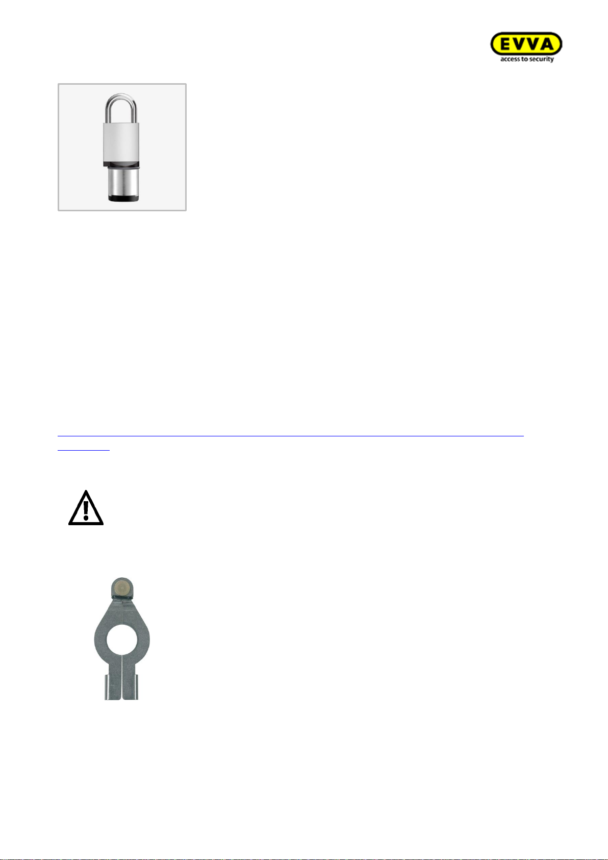
2.1.3.3 Cylinder tool
Figure 10: Cylinder tool (sample image)
Xesar cylinders provide a special opening mechanism to protect from manipulation. The dedicated
special tool is required for assembly and disassembly as well as battery replacements.
Order the cylinder tool separately. It is not enclosed with Xesar cylinders.
Page 25

25
KPM.X.Systemhandbuch_X3.0.EN.V1.9 | 05/2019 | Subjects to misprints and technical changes.
Please note the instructions in the Xesar cylinder assembly manual
or watch the video instructions: http://video.evva.com/tutorials/xesar/expzkzs/expzkz-s1/de/http://video.evva.com/tutorials/xesar/expzkzs/expzkz-s-1/de/
The cylinder tool is optionally available.
Product code: E.ZU.PZ.ZW.V2
Page 26
26
KPM.X.Systemhandbuch_X3.0.EN.V1.9 | 05/2019 | Subjects to misprints and technical changes.
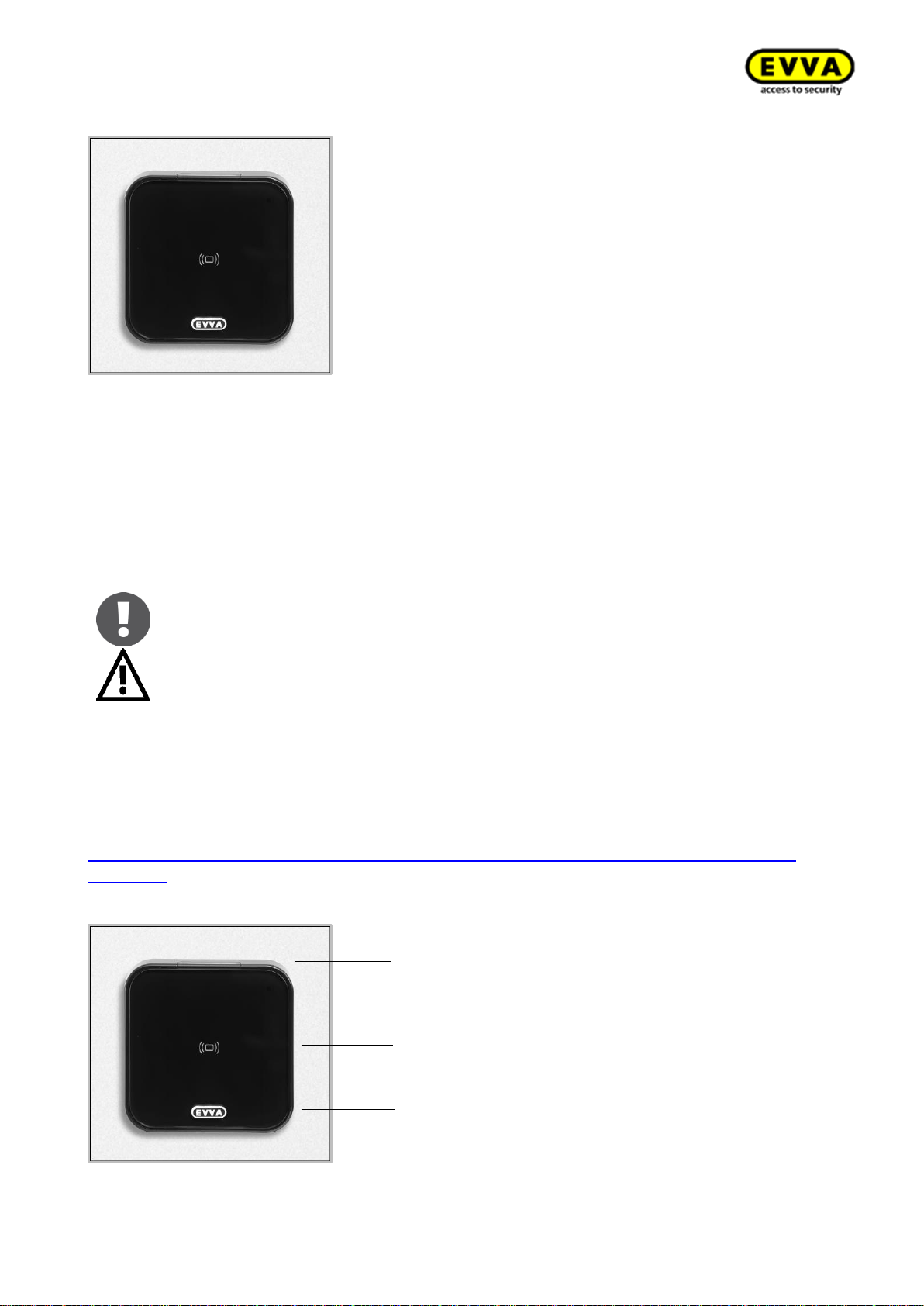
2.1.4 Xesar wall reader
Figure 11: Xesar wall reader (sample image)
Xesar wall readers are suitable for indoors and outdoors, surface-mounted or flush installation and
for zones critical to security.
Please use the dedicated seal enclosed with the product for use outdoors or in zones that are
exposed to water as well as in the event of surface-mounted installation. Observe the information
in the assembly manual. Xesar wall readers are connected to the Xesar control unit and supplied
with power using a connecting cable.
Please note Xesar wall readers can only be used in connection with Xesar
control units.
The connector is intended solely to synchronise the unit with the Xesar tablet, Xesar wall readers cannot be operated with the optionally
available emergency power device!
Connect the Xesar wall reader to Xesar control units to operate electronic components, such as
motorised cylinders, swing doors, sliding doors, etc.
Please check carefully to make sure the Xesar product you selected is suitable for your application.
We have made the required data sheet available in the download section of our homepage:
https://www.evva.com/uk-en/products/electroniclockingsystemsaccesscontrolsystems/xesar/#tab6
2.1.4.1 Xesar wall reader — functional description
Figure 12: Xesar wall reader (sample image)
Visual signals
Reader unit + ON/OFF status light
Connection cable
Page 27
27
KPM.X.Systemhandbuch_X3.0.EN.V1.9 | 05/2019 | Subjects to misprints and technical changes.
Visual and audible signalling
Xesar wall readers indicate events visually and audibly. For this purpose, there is an LED at the top
edge of the Xesar wall reader. For a list of all available signals please refer to section:2.3 Xesar
access components signal events
Reader area, ON/OFF status light
The reader unit sensor is located behind the glass panel of the Xesar wall reader between the EVVA
logo and the LED. The status light of the Xesar wall reader lights up continuously during on-going
operation to facilitate localising the reader unit in dark environments.
Functional principle
Hold an identification medium to the reader unit and the Xesar control unit (connected to the Xesar
wall reader) checks the identification medium. The authorisation is switched according to the
jumper settings and the respectively addressed relay of the Xesar control unit and the configuration.
(See cover plan in the Xesar control unit -> JP2).
Xesar control units feature an event memory for the last 1,000
events. Once the event memory is full, the system overwrites the oldest entries with the most
recent events. For this reason, it is important to regularly synchronise events to prevent event
records from being lost.
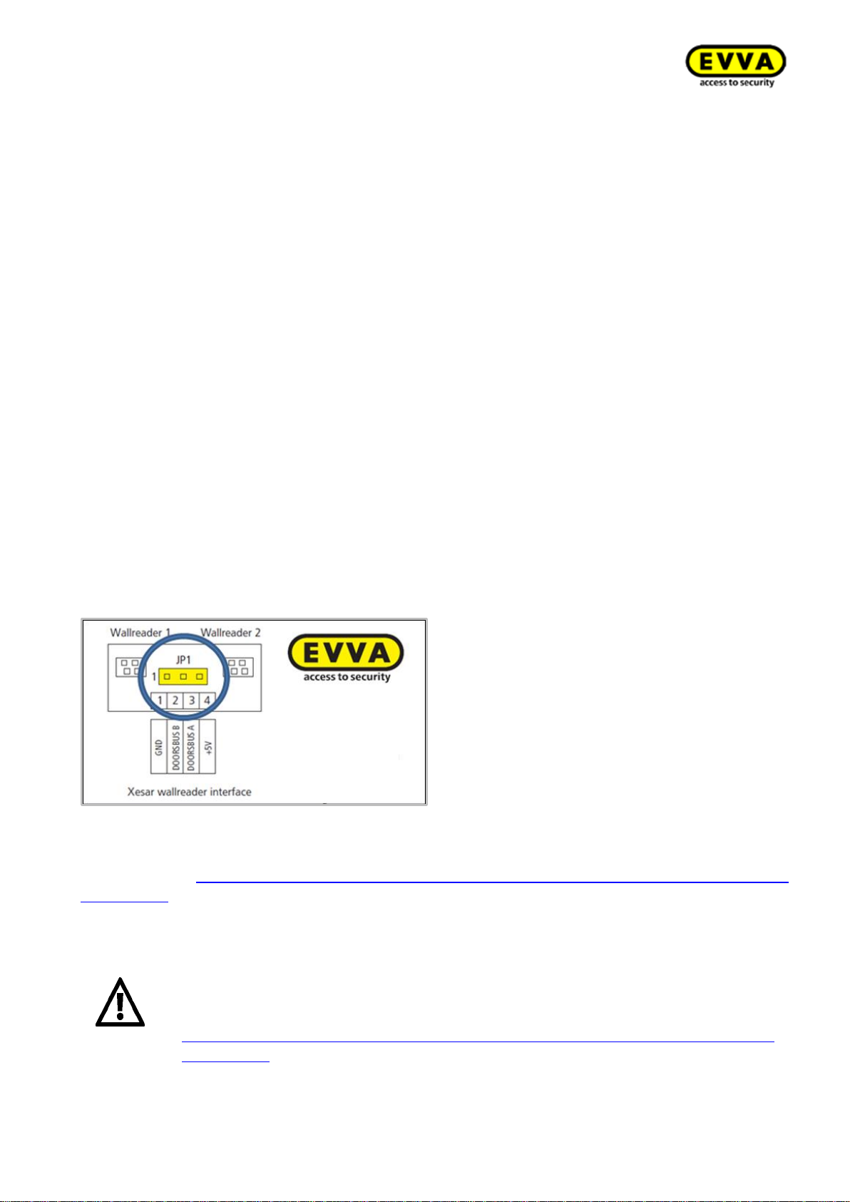
2.1.4.2 Xesar wall reader connection print
Use the connection label to connect Xesar wall readers to the connecting cables of the Xesar
control unit. Please note the data and information in the assembly manual enclosed with
your Xesar product; in particular the jumper position of the JP1 jumper to prevent malfunctions.
Figure 13: Xesar wall reader connection print (sample image)
We have provided the assembly manual and the data sheet of the corresponding Xesar product on
our homepage: https://www.evva.com/uk-en/products/electroniclockingsystemsaccesscontrolsys-
tems/xesar/
Important notes on use, general legal information, danger to life and limb,
risk of explosion, climatic and environmental effects, installation instructions and use of batteries; please refer to our safety instructions on operation and cleaning which are included and can be found on our website at:
https://www.evva.com/uk-en/products/electroniclockingsystemsaccesscontrolsystems/xesar/
Page 28
28
KPM.X.Systemhandbuch_X3.0.EN.V1.9 | 05/2019 | Subjects to misprints and technical changes.
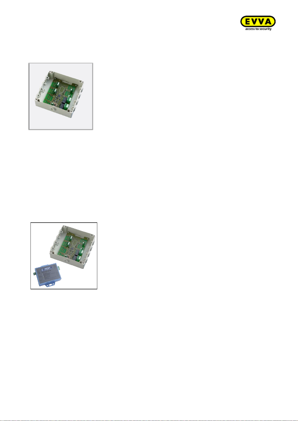
2.1.5 Xesar wall reader control unit
Figure 14: Xesar wall reader control unit (sample image)
The Xesar control unit can be exclusively used in conjunction with Xesar wall readers. Each control
unit can be connected to one or two Xesar wall readers. Xesar control units connected to Xesar wall
readers must be installed indoors in zones protected from manipulation.
Xesar control units are supplied with power using power supply unit. In the event of power failure
they are equipped with data buffers for a maximum of 72 hours, providing the Xesar control unit
had been previously active for a minimum of six hours.
2.1.6 Xesar wall reader online control unit
Figure 15: Xesar wall reader online control unit (sample image)
The Xesar wall reader online control unit can be exclusively used in conjunction with Xesar wall
readers. Each online control unit can be connected to a maximum of one Xesar wall reader. Xesar
control units connected to Xesar wall readers must be installed indoors in zones protected from
manipulation.
Online control unit is connected via an Ethernet adapter LAN to the system computer. If the LAN
connection is interrupted, then the Xesar wall reader behaves as an offline wall reader. Xesar online
control units are supplied with power using power supply unit. In the event of power failure, they
are equipped with data buffers for a maximum of 72 hours, providing the Xesar control unit had
been previously active for a minimum of six hours.
Page 29
29
KPM.X.Systemhandbuch_X3.0.EN.V1.9 | 05/2019 | Subjects to misprints and technical changes.
For more detailed information, please refer to the product catalogue in the download section of our
homepage: https://www.evva.com/uk-en/products/electroniclockingsystemsaccesscontrolsys-
tems/xesar/
Important notes on use, general legal information, danger to life and limb,
risk of explosion, climatic and environmental effects, installation instructions
and use of batteries; please refer to our safety instructions on operation and
cleaning which are included and can be found on our website at:
https://www.evva.com/uk-en/products/electroniclockingsystemsaccesscontrolsystems/xesar/
EVVA recommends operating the Xesar wall reader control unit using an independent power supply and provide an uninterrupted 12 V power supply.
This consequently prevents system failure and safeguards access.
As soon as the control unit has been connected to the power supply
for six hours the system ensures the time settings are maintained for
a minimum of 72 hours in the event of a power cut.
Assemble the component as per the assembly manual enclosed with the product.
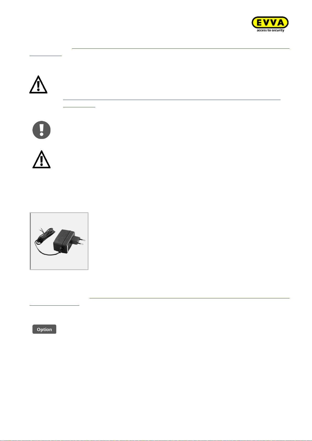
2.1.7 Mains adapter for control unit
Figure 16: Mains adapter (sample image)
Please refer to the product catalogue in the general download section of our homepage for more
detailed information: https://www.evva.com/uk-en/products/electroniclockingsystemsaccesscon-
trolsystems/xesar/
The control unit mains adapter is optionally available.
Product code: E.ZU.WL.NT.V2
2.2 Installing Xesar access components
Please note that specialist personnel must install Xesar access components as per the notes and
information as well as the assembly manual enclosed with the product.
EVVA provides a host of different installation tools to make installing your Xesar system easier.
Visit our website.
Page 30
30
KPM.X.Systemhandbuch_X3.0.EN.V1.9 | 05/2019 | Subjects to misprints and technical changes.
Language-neutral assembly manual
To support Xesar access component assembly EVVA provides language-neutral assembly which
can be found on the packaging of the corresponding product or on our homepage.
https://www.evva.com/uk-en/products/electroniclockingsystemsaccesscontrolsystems/xesar/
Product-specific assembly video clips
We have provided assembly video clips with demonstrations of complex assembly steps here:
http://video.evva.com/tutorials/xesar/exdrz1/exdrz1-1/ domainhttp://video.evva.com/tutori-
als/xesar/exdrz1/exdrz1-1/
Language-neutral drilling template
EVVA provides a single-use, cardboard drilling template without text to support the assembly
of versions requiring one or several drilled holes. They are printed on the corresponding product
packaging and are available in our homepage in the general download section:
https://www.evva.com/uk-en/products/electroniclockingsystemsaccesscontrolsystems/xesar/
The assembly manuals and the packaging feature QR codes which will take
you directly to the corresponding video sequence or assembly manual.
You must observe the listed sequence of installation steps as otherwise malfunctions may occur.
Installation using drilling template
Figure 17: Drilling template (sample image)
EVVA provides a high-quality, metal drilling template to facilitate preparing the door for an assembly of any type of Xesar escutcheons and Xesar handles.
An adjustable stop safeguards that holes are correctly aligned and it enables adaptations of the
settings to match the requirements of any door situation. Hardened metal drilling sleeves guarantee
a long service life even after intense use.
The drilling template is optionally available.
Product code: E.ZU.BE.BS.V1
Page 31
31
KPM.X.Systemhandbuch_X3.0.EN.V1.9 | 05/2019 | Subjects to misprints and technical changes.
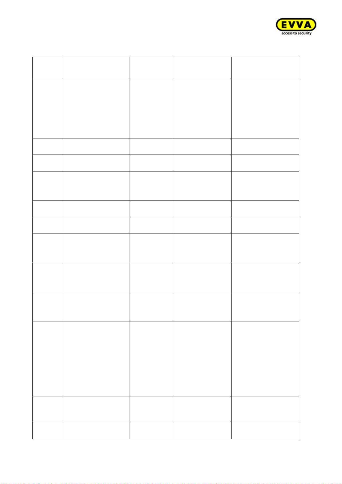
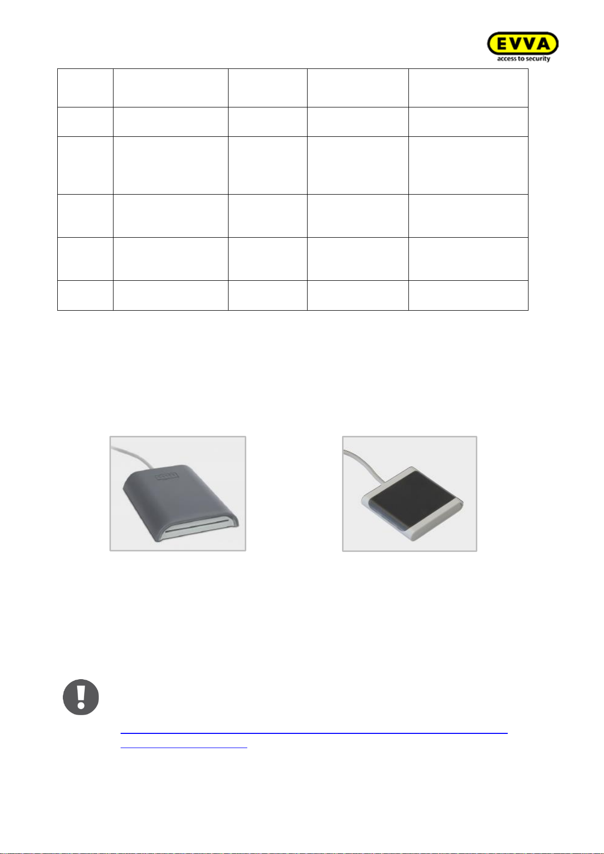
2.3 Xesar access components signal events
Signal
number
Event
Visual
signal
Audible signal
Note
Signal 1
Unlocking attempt
with authorised medium
⚫⚫⚫⚫⚫
mmmmm
General: If several
cards are in use, the
signal is only output after the last card is read
(yes, no or no EVVA
card)
Signal 2
End of release
⚫⚫⚫⚫⚫
ttttt
Signal 3
Rejected
medium
⚫⚫-⚫⚫-⚫⚫-⚫⚫
hh-hh-hh-hh
Signal 4
Unlocking attempt
with authorised medium and activated Office Mode
⚫⚫⚫⚫--⚫⚫⚫⚫
tttt—hhhh
Signal 5
Start of Office Mode
⚫⚫⚫⚫--⚫⚫⚫⚫
tttt—hhhh
Signal 6
End of Office Mode
⚫⚫⚫⚫--⚫⚫⚫⚫
hhhh—tttt
Signal 7
Opening attempt with
authorised medium,
signal indicates
drained battery
⚫⚫--⚫⚫--⚫⚫-⚫⚫
h----h----h----h----
Signal 8
Battery inserted or
component reboot
⚫⚫--⚫⚫--⚫⚫
tt—mm—hh
After having inserted
batteries, battery
charge status display
possible
Signal 9
Medium without EVVA
segmentation; medium faulty, other system
No signals
Signal 10
Hardware faulty
⚫---⚫---⚫---
⚫---⚫---⚫---
⚫---⚫---⚫---
⚫---⚫---⚫---
⚫---⚫---⚫---
⚫---⚫---⚫---
⚫---⚫---
mmm---mmm--
-mmm---mmm-
--mmm--mmm---mmm--
-mmm---mmm-
--mmm---
Signal 11
Communication
process with PPD
(Xesar)
⚫-⚫-⚫-⚫-⚫-
⚫
Signal 12
Communication
successful
⚫⚫⚫⚫⚫
hhhhh
Page 32
32
KPM.X.Systemhandbuch_X3.0.EN.V1.9 | 05/2019 | Subjects to misprints and technical changes.
Signal
number
Event
Visual
signal
Audible signal
Note
Signal 13
Communication
unsuccessful
⚫⚫⚫⚫⚫
ttttt
Signal 14
Medium authorised
offline
⚫⚫--⚫⚫⚫⚫
mm-mm-mm
Signal 15
Rejected medium
offline
⚫⚫--⚫⚫⚫⚫
mm-mm-mm
Signal 16
Online operation
failed
⚫⚫--⚫⚫⚫⚫
Visual LED signals: = Red and green simultaneously⚫
Audible signals: h = high-pitched sound, m = medium-pitched sound, t = low-pitched sound
Each signal corresponds to a duration of 50 ms.
Pauses are indicated by "–".
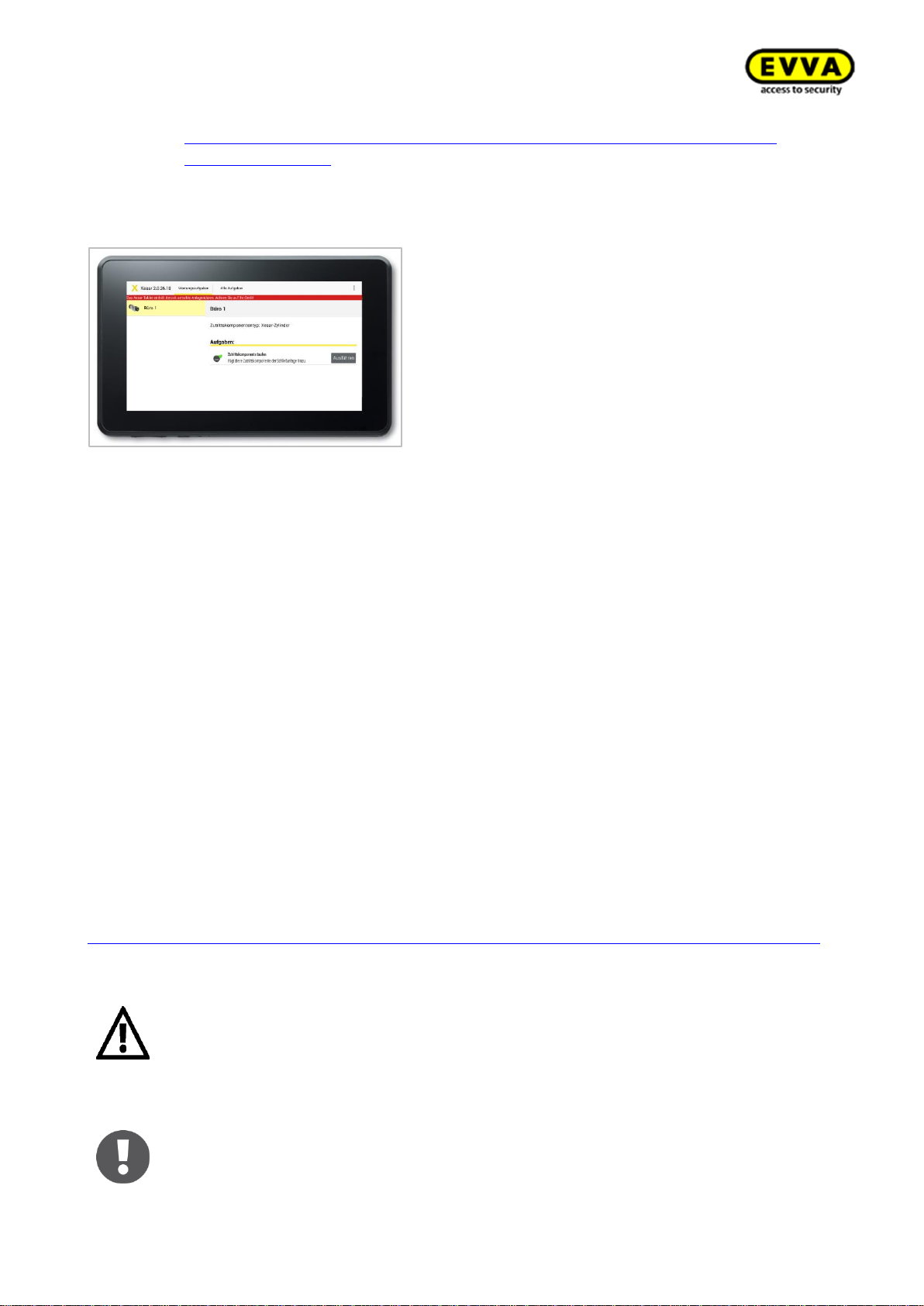
2.4 Xesar coding station
Figure 18 – Xesar coding station (sample image)
Figure 19 – Mini coding station (sample image)
The Xesar coding station is a read/write device for any type of contactless identification media as
well as the contact-based Admin Card, which is one of the system cards: (see section Admin
Card ). The Xesar coding station provides a separate card slot on the front of the Xesar coding
station for the Admin Card. Install the associated driver and connect the Xesar coding station to
the USB port of the computer where you installed Xesar software.
The mini coding station cannot be used to operate the AdminCard
Note: we have provided the driver required for the Xesar coding station in
the download section of our homepage:
https://www.evva.com/uk-en/products/electroniclockingsystemsaccesscontrolsystems/xesar/#tab6
Page 33
33
KPM.X.Systemhandbuch_X3.0.EN.V1.9 | 05/2019 | Subjects to misprints and technical changes.
Additional specifications are available on the corresponding data sheet at
https://www.evva.com/uk-en/products/electroniclockingsystemsaccesscontrolsystems/xesar/
2.5 Xesar tablet
Figure 20: Xesar tablet (sample image)
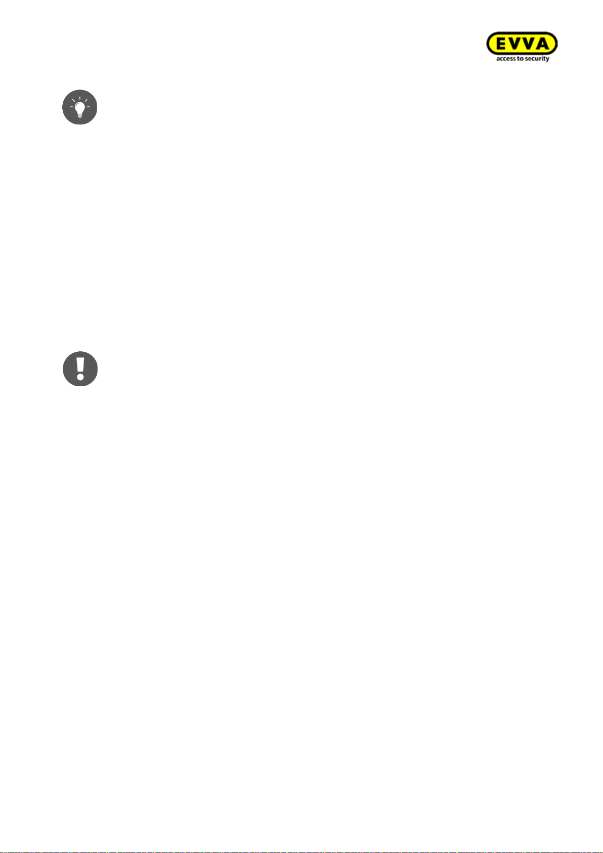
The Xesar tablet is intended to synchronise and transfer information between Xesar software and
Xesar access components.
The Xesar programming unit includes a proprietary EVVA connection cable. Use the connection
cable to link your Xesar access components to the Xesar tablet. You can identify the connection
cable by the EVVA logo located on the USB connector.
All Xesar access components feature an interface at the front, behind the connector cover (EVVA
logo). Slightly press towards the inside on the left-hand side of the EVVA logo (near the "E") and
fold out on the right-hand side (near the "A") to access it.
The integrated interface of the Xesar access component in conjunction with the Xesar programming
unit is designed to synchronise Xesar software and Xesar access components only.
After use, once again carefully close the connector cover (EVVA logo) of your Xesar access components to continue to protect the connector from penetrating dust and humidity.
For this purpose, do not use pointed objects to prevent damage.
Please refer to the corresponding data sheet for additional specifications at
https://www.evva.com/uk-en/products/electroniclockingsystemsaccesscontrolsystems/xesar/
.
Do not install additional applications as otherwise EVVA will be unable to safeguard the product security and functionality of the system!
Do not install operating system updates!
The Xesar tablet is unsuitable as an emergency power supply for batteryoperated Xesar access components.
Page 34
34
KPM.X.Systemhandbuch_X3.0.EN.V1.9 | 05/2019 | Subjects to misprints and technical changes.
We recommend that you regularly synchronise data at each Xesar access
component to be able to quickly synchronise events with the software (attention: max. 1000 events per access component, after which the oldest
events are overwritten again). If you have installed online components, the
data is updated using XVN (see: → 8.15 Xesar virtual network (XVN)) Synchronise each access component at a minimum of once a year to make sure
the time has been synchronised with the system.
Functional principle
Any maintenance tasks or any other tasks for the corresponding Xesar access component are loaded
and logged upon each synchronisation between programming unit and Xesar software.
The connection cable enclosed with your Xesar tablet enables a connection to the Xesar access
component and subsequently represents an option to exchange data using the Xesar app. For more
information read section: → 8.14.1 Xesar tablet app
Xesar tablet application (app):
The Xesar application has already been preinstalled on your programming device. A detailed operating manual of the Xesar app for operating your locking system can be found in the chapter →
8.14.1 Xesar tablet app
We have enclosed the manufacturer's independent user guide for the Xesar
tablet. It has been enclosed with the product packaging.
Fully charge your Xesar tablet prior to first use!
The app enables the following:
• Initialising Xesar access components (first initialisation during commissioning)
• Synchronising changed door parameters in Xesar access components
• Transferring blacklists to Xesar access components
• Checking the battery status (also for third-party systems!)
• Checking the current firmware version (also for third-party systems!)
• Firmware updates (Xesar access components in battery mode are supplied with energy
from the Xesar tablet during firmware updates)
• You can retrieve Xesar access component events
• Resetting Xesar access components to construction site mode
• Automatically synchronising the time in access components upon communication be-
tween tablet and access components
Page 35
35
KPM.X.Systemhandbuch_X3.0.EN.V1.9 | 05/2019 | Subjects to misprints and technical changes.
2.6 Xesar emergency power device
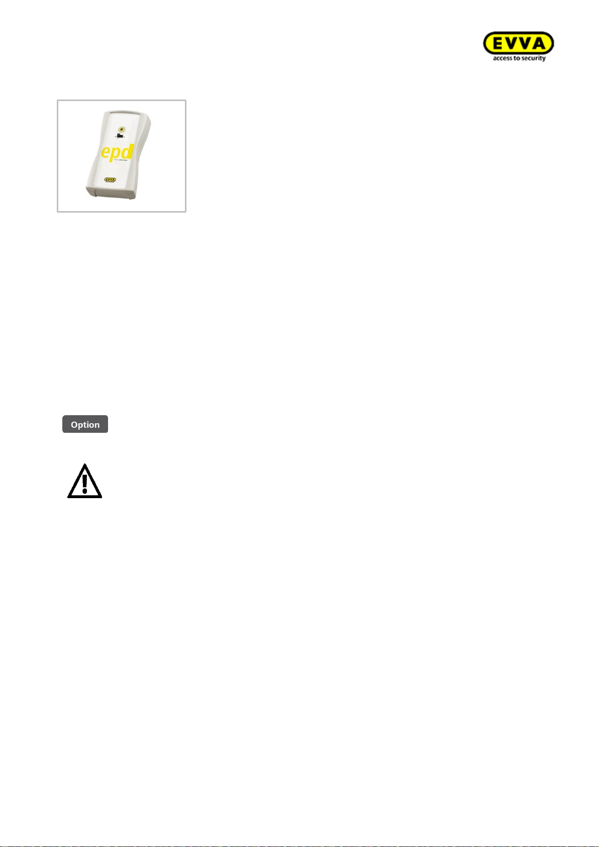
Figure 21: Emergency power device (sample image)
The emergency power device supplies access components with power to enable operation in the
event that the batteries have been drained. For this purpose, connect the emergency power device
connection cable to the corresponding interface and then switch it on. No other interactions with
the emergency power device are required. A medium with valid Master Key authorisation is required
to operate the Xesar access component.
Immediately replace batteries after having used the emergency power device to operate access
components and subsequently update access components; using the Xesar tablet to once again
enable access with all authorised identification media.
The installed interface below the EVVA logo in conjunction with the emergency power device is
intended for emergency power supply only and it is not required as part of normal operation.
The emergency power device is optionally available.
Product code: E.ZU.NG.V1
Please note, you need an identification medium with "MasterKey" authorisation to open Xesar access components supplied with emergency power, as the time setting is lost if the power supply is interrupted for too long which causes standard media to be unable to open
them.
Page 36
36
KPM.X.Systemhandbuch_X3.0.EN.V1.9 | 05/2019 | Subjects to misprints and technical changes.
2.7 Admin Card
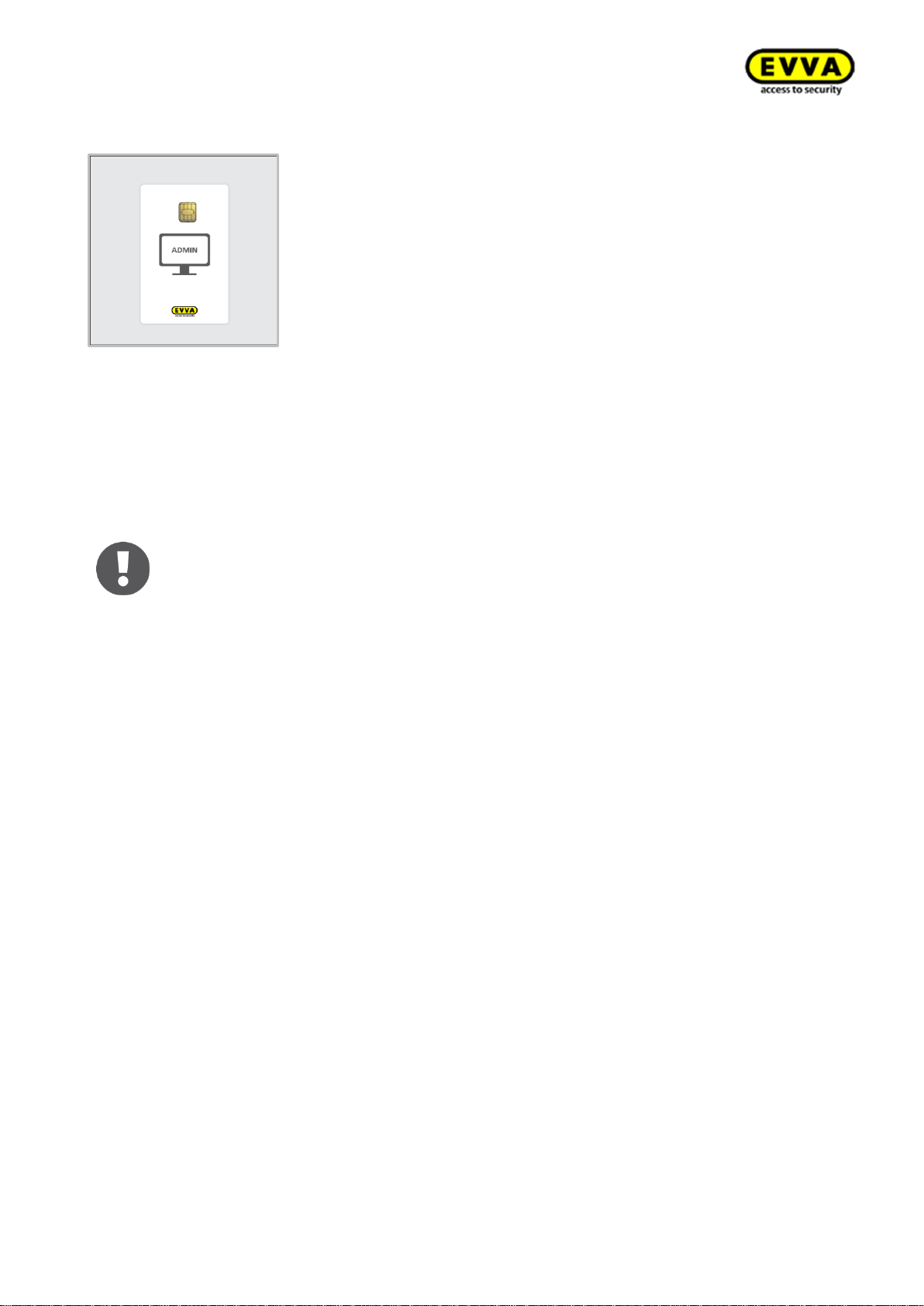
Figure 22: Admin Card (sample image)
The Admin Card is a contact-type, electronic chip card in standard format. It enables to access the
Xesar software and uniquely identifies the system. Any KeyCredits purchased to make changes to
authorisations are saved on the card (also applies to KeyCredits Lifetime).
System changes, such as adding KeyCredits, can exclusively be carried out if there is a valid Admin
Card in the Xesar coding station. Admin Cards are required for licence operations only!
Note: The Admin Card is not transferable and hence it cannot be used for
other systems.
You can replace the Admin Card in the event of loss or damage.
(See section: 5.2 AdminCard exchange:)
Page 37
37
KPM.X.Systemhandbuch_X3.0.EN.V1.9 | 05/2019 | Subjects to misprints and technical changes.
2.8 Identification media
An identification media is a non-contact RFID chip based MIFARE DESFire EV1 with an overall
memory capacity of 4 kB.
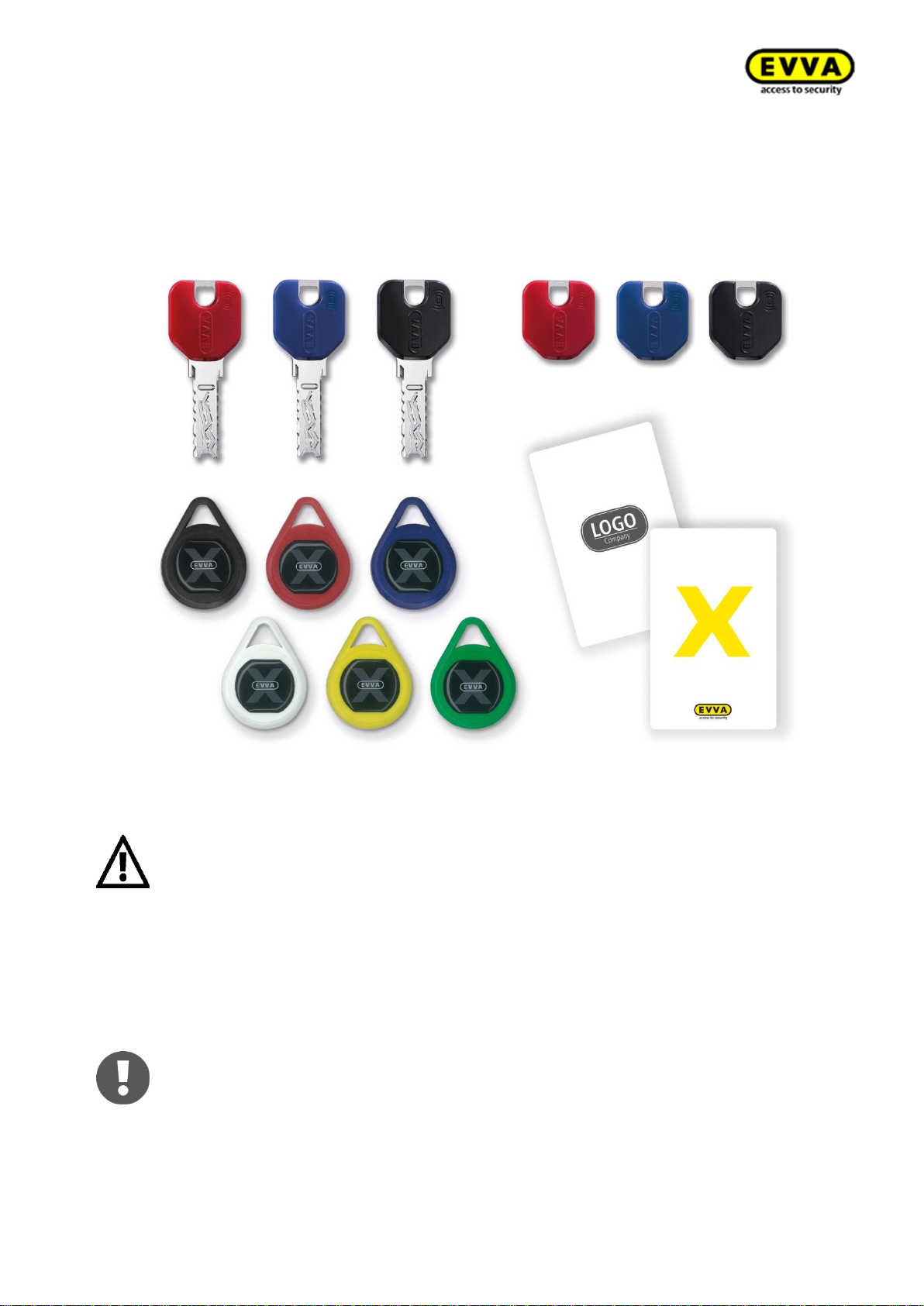
Overview of available identification media:
Figure 23 – Identification media overview
Do not place more than one identification medium on the Xesar coding station. Otherwise the identification media may be incorrectly
configured.
Please keep metal objects away from the coding station as they may
impair reader functionality.
Once your system is no longer in construction mode following commissioning, you can use identification media programmed with the Xesar coding station to open Xesar access components.
Construction mode is active as long as the Xesar access component has not
been assigned to a system. Every Xesar access component has this status
upon delivery.
Page 38
38
KPM.X.Systemhandbuch_X3.0.EN.V1.9 | 05/2019 | Subjects to misprints and technical changes.
All identification media types are programmed using the Xesar coding station
by placing the identification media on an operating coding station and following the corresponding instructions in the software.
Please refer to the corresponding data sheet for additional specifications at
https://www.evva.com/uk-en/products/electroniclockingsystemsaccesscontrolsystems/xesar/
An identification medium can feature authorisations for a maximum of 96
door zones (regardless of the number of access points associated with the
area) and additionally 32 access points.
2.9 Construction Card (construction site medium)
Figure 24: Construction Card (sample image)
The Construction card is a contactless RFID chip card, based on MIFARE DESFire EV1, which is able
to open Xesar access components in construction mode.
Manual Office Mode is also available in addition to conventional access component operation (see
section:). The Construction Card is ready for use immediately and it must not be programmed using
the Xesar coding station.
Construction mode is active as long as the Xesar access component has not
been assigned to a system. Upon delivery, each Xesar access component has
the construction mode status.
Please note that your system can be operated with any Construction
Card when it is in construction mode. Initialise your access
components as soon as possible! However, we recommend creating
authorisation profiles and associated zones as well as time profiles in the
management software first, to then simultaneously configure these as part
of the baptizm to guarantee efficient system commissioning.
See section: →7Commissioning Xesar software)
Page 39
39
KPM.X.Systemhandbuch_X3.0.EN.V1.9 | 05/2019 | Subjects to misprints and technical changes.
3 System requirements
Xesar can be operated as a multi-user system and a single-user system. System requirements in
the following section.
3.1 Xesar 3.0 single-user system
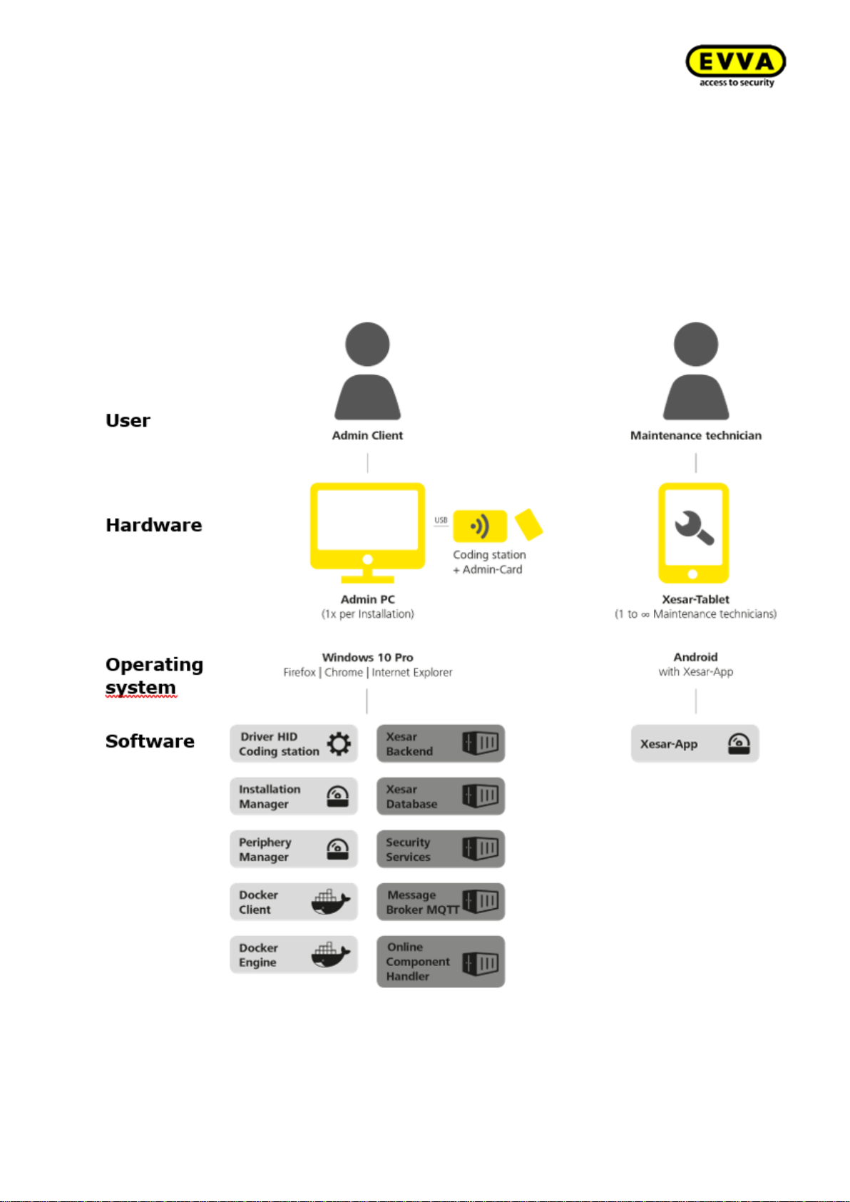
We do not recommend PC single-user operation for 24/7 permanent operation and use with
online components. If the single-user PC is not in operation, then the wall scanner is in offline
mode and identification media are not updated.
Page 40
40
KPM.X.Systemhandbuch_X3.0.EN.V1.9 | 05/2019 | Subjects to misprints and technical changes.
The following minimum hardware requirements must be complied with for operation as a PC single-user system:
x86-64 compatible processor (CPU) 1-2 core, 2.4 GHz or higher
Hardware support for virtualisation
RAM: ≥ 8 GB (with OS)
Hard disk space: ≥ 60GB
Direct internet access without proxy to unlock KeyCredits and licences to access
EVVA secured authentic and un-manipulated software delivery
Local LAN with low latency (ping <10ms, roundtrip <30ms); WiFi for Xesar tablet
sync and access to the services provided
1 × USB host 2.0
1 x EVVA coding station with support for contactless RFID cards (Mifare Desfire
EV1; ISO 14443) and slot for Admin Card
Keyboard and mouse
1024x768 screen resolution, recommended: 1920x1080
Operating system: Windows 10 Pro 64 bit version 1511 (build 10586) or higher
HTML5/CSS3 compatible browser, activated with Java script
Local network:
• WiFi (wireless): IEEE.802.11 g, n
• Protocols:
o IPv4
o HTTP/HTTPS (with TLS)
Docker Client with support for API 1.24, Docker Compose 1.10.0+ (installed as part
of the Docker installation on the Admin PC)
Docker Engine 1.12.0+ with support for API 1.24 (will be installed on the admin PC
as part of Docker installation)
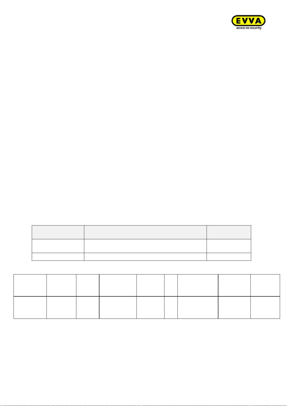
Services provided by EVVA on the Internet:
Service
URL Port:
Private addresses
Trusted Registry
https://sfw.evva.com:443
https://sfw.evva.com:4443
Fix
Licence service
https://licence.evva.com:8072
Fix
Service catalogue: Communication, Online wall reader – Server (backend)
Service
Network
Default
port
Port address
Protocol
TLS
Use
Utilising
compo-
nents
Providing
compo-
nents
Online dealership com-
ponents
LAN/WLAN
9081
configurable
NWP
Yes
Communication
with the Xesar
software.
Xesar online
wall reader
Online
component
dealership
It may be possible to implement the following solutions (please consult EVVA Technical Offices):
• Installation manager operated on a virtual machine
• Installation manager operated on a different Windows operating system
• Use of other browsers compatible with HTML5/CSS3
Page 41
41
KPM.X.Systemhandbuch_X3.0.EN.V1.9 | 05/2019 | Subjects to misprints and technical changes.
3.2 Xesar 3.0 multi-user system server
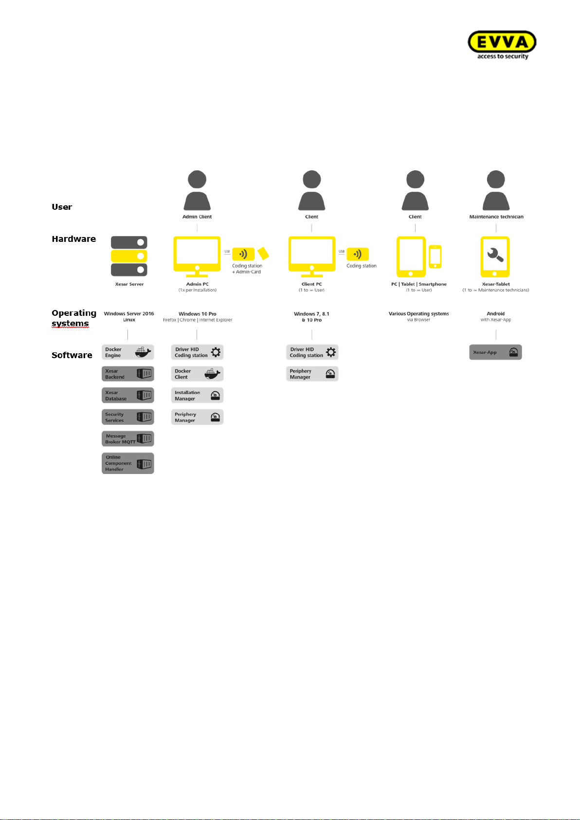
The multi-user system consists of a server, an Admin PC with coding station & Admin Card and
optionally further client PCs with/without coding stations. Optionally, mobile devices can also be
accessed via a browser as a client without coding station The Xesar Tablet is used as a maintenance tool for sytem management. Here is an overview of different variations:
3.2.1 System requirements – Server
24/7 server operation is required for a multi-user solution.
The following minimum requirements must be met:
x86-64 compatible processor (CPU), at minimum quad core ≥ 1.5-2.3 GHz
Hardware support for virtualisation
Working memory (RAM): ≥ 4 GB (with OS, at least 2 GB for the server software
stack)
Hard disk space, SSD recommended: ≥ 40GB (note system size and planned
runtime for dimensioning)
Direct Internet access without proxy to unlock KeyCredits and licences to access
EVVA secured authentic and un-manipulated software delivery
Lokal LAN with low latency (ping<10ms, roundtrip <30ms)
WiFi for Xesar tablet synchronisation with server
Access option from local LAN to server for provided services
Docker Engine 1.12.0+ with support for API 1.24 (will be installed as part of Docker
installation)
Page 42
42
KPM.X.Systemhandbuch_X3.0.EN.V1.9 | 05/2019 | Subjects to misprints and technical changes.
Service catalogue: Management of a Xesar 3 system
See appendix: 3.4: Service/communication
• Server – Admin PC
• Server – Client PC
• Server - Online wall reader
Tested operating systems:
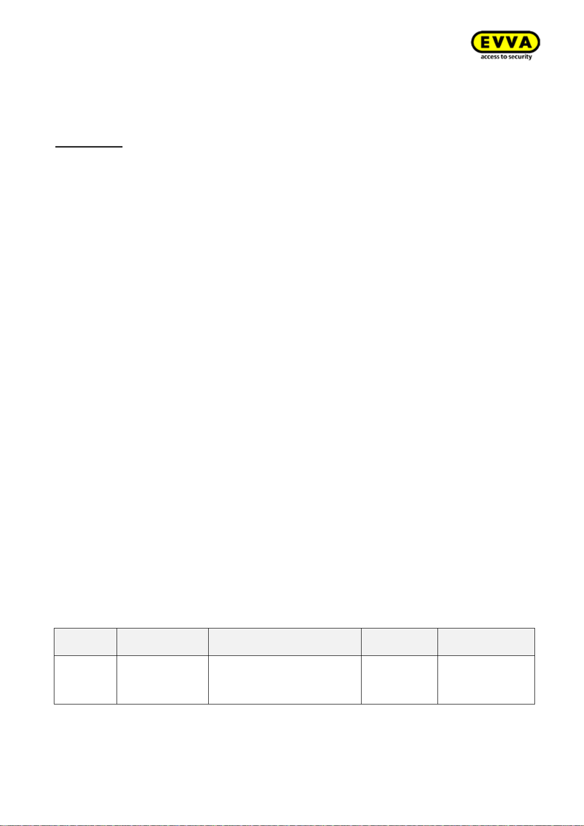
OS
OS type
Version
Virtualisation
possible
Ubuntu
Linux
14.04 (Trusty, LTS)
16.04 (Xenial, LTS)
18.04.1 / 18.04.2 LTS
Yes
Windows Server
Windows
2016 data centre
2016 standard
No
DSM1
Linux
6.1
6.2
No
Photon OS2
Linux
2.0
Yes
Important:
Xesar must meet real-time requirements when communicating with its online components. In the event that Windows Server 2016 is not exclusive used by Xesar software,
operation as hypervisor must ensure that the required resources are permanently allocated.
Non-tested operating systems:
OS
OS type
Version
Virtualisation
possible
Cent OS
Linux 7 Yes
Debian
Linux
9 (Stretch)
8 (Jessie, LTS)
Yes
Fedora
Linux
26 (27)
Yes
1
Operating system for NAS synology; verification on DS916+
2
Container optimised operating system recommended by VMware for VMware vSphere ESXi 6.x
Page 43
43
KPM.X.Systemhandbuch_X3.0.EN.V1.9 | 05/2019 | Subjects to misprints and technical changes.
Due to the large number of possible operating systems not all variants can be tested for
compatibility by EVVA.
If an operating system is to be used that is not tested by EVVA, please consult the responsible EVVA technical office beforehand.
Important:
Due to the ongoing developments in the IT market, please consult your EVVA partner or
the EVVA Technical Offices with regard to the current compatibility list.
3.2.2 System requirements - Admin PC with coding station and Admin
Card
The following minimum requirements must be met to operate the Xesar system management
software (installation manager):
x86-64 compatible processor (CPU) 1-2 core, 2.4 GHz or higher
Hardware support for virtualisation
Working memory (RAM): ≥ 4 GB (with OS, at least 1 GB for the applications: In-
stallation manager & periphery manager)
Hard disk space: ≥ 5GB
Direct Internet access without proxy to unlock KeyCredits and licences to access
EVVA secured authentic and un-manipulated software delivery
Local LAN to access the services provided by Xesar 3.0 server
1 × USB host 2.0
1 x EVVA coding station with support for contactless RFID cards (Mifare Desfire
EV1; ISO 14443) and slot for Admin Card
Keyboard and mouse
Operating system: Windows 10 Pro 64 bit version 1511 (build 10586) or higher
HTML5/CSS3 compatible browser, activated with Java script
Docker Client with support for API 1.24, Docker Compose 1.10.0+ (installed as part
of the Docker installation on the Admin PC)
Service catalogue: Management of a Xesar 3 system
See appendix: Service/communication
• Admin PC - Server
PC operating systems:
OS
Version
Browser
Verified by
EVVA
EVVA coding
station
Windows
10 Pro (V 1511
(build 10586))
• Firefox from version 47
• Chrome from version 48
• Internet Explorer from
version 11
Yes
Yes
It may be possible to implement the following solutions (please consult EVVA Technical Offices):
• Operating the Installation Manager on a virtual machine on the server (Admin Card is con-
nected via client PC)
Page 44
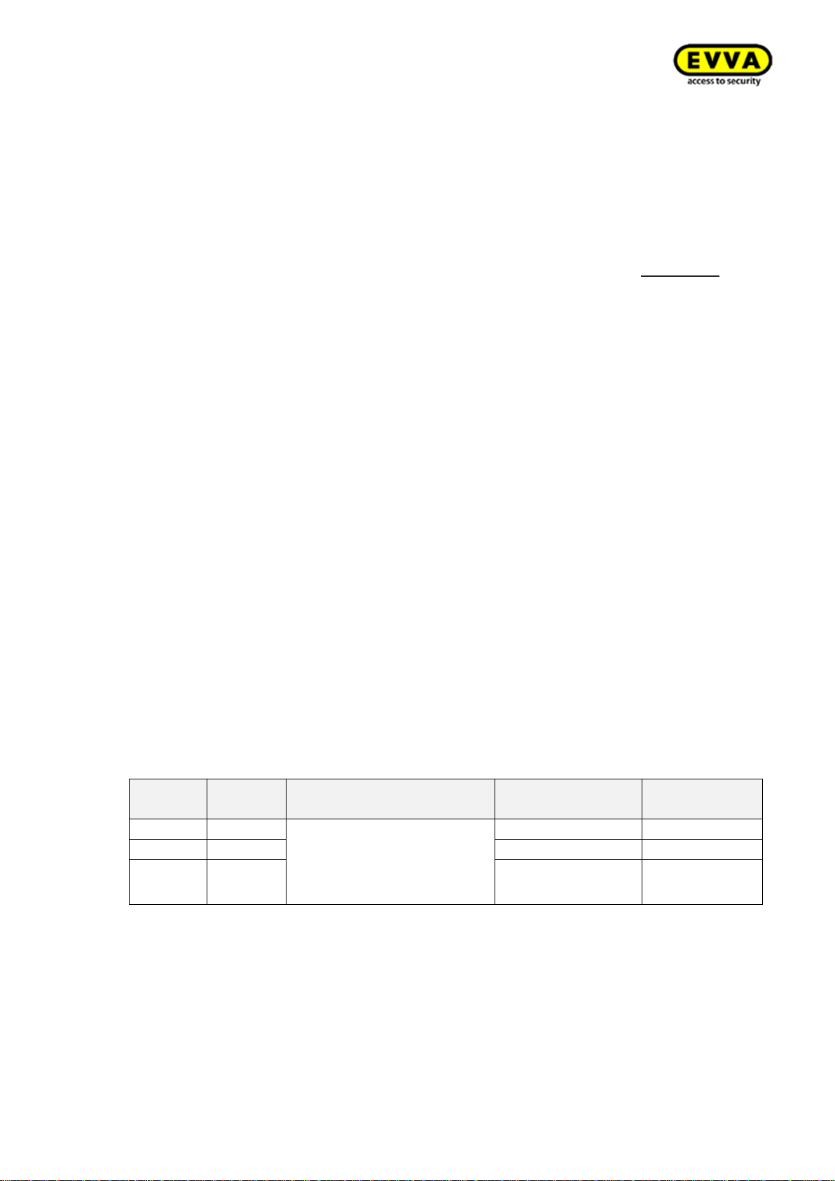
44
KPM.X.Systemhandbuch_X3.0.EN.V1.9 | 05/2019 | Subjects to misprints and technical changes.
• Installation manager operated on a different Windows operating system, such as Windows
7, 8.x, Server 2012 R2 and Server 2016 data centre
• Operation of the periphery manager on a different Windows operating system, such as
Windows Server 2012 R2 and Server 2016 data centre
• Operation of the periphery manager operated on other operating systems (on request
only)
• Use of other browsers compatible with HTML5/CSS3
3.2.3 System requirements – client PC with coding station without Ad-
min Card
The following minimum requirements must be met to operate the client PC with coding station
within a multi-user system:
x86-64 compatible processor (CPU) 1-2 core, 2.4 GHz or higher
Working memory (RAM): ≥ 4 GB (with OS, at least 512Mb for the peripheral manager application, 1-2 GB for a supported browser)
Hard disk space: ≥ 2GB
Local LAN with access to the services provided by Xesar 3.0 server
1 × USB host 2.0
1 x EVVA coding station with support for contactless RFID cards (Mifare Desfire
EV1; ISO 14443)
Keyboard and mouse
1024x768 screen resolution, recommended: 1920x1080
HTML5/CSS3 compatible browser, activated with Java script
Service catalogue: Server and workstation in a muti-user system
See appendix: 3.5 Communication, Client PC - Server (backend)
• Client PC - Server
Operating systems:
OS
Version
Browser
Verified by EVVA
EVVA coding
station
Windows
7 Pro
• Firefox from version 47
• Chrome from version
48
• Internet Explorer from
version 11
Yes
Yes
Windows
8.1 Pro
Yes
Yes
Windows
10 Pro
Yes
Yes
It may be possible to implement the following solutions (please consult EVVA Technical Offices):
• Operation of the periphery manager on a different Windows operating system, such as
Windows Server 2012 R2 and Server 2016 data centre
• Operation of the periphery manager on other operating systems (on request only)
• Use of other browsers compatible with HTML5/CSS3
Page 45
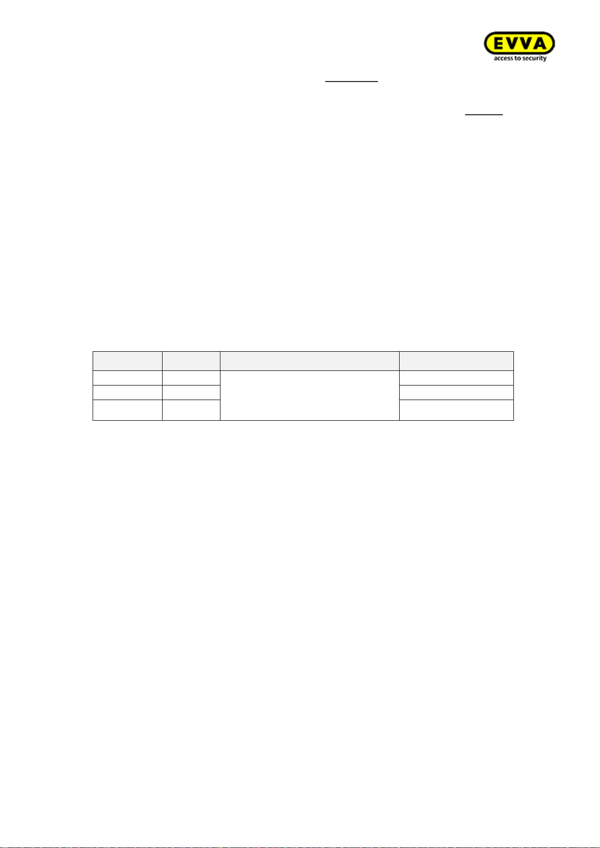
45
KPM.X.Systemhandbuch_X3.0.EN.V1.9 | 05/2019 | Subjects to misprints and technical changes.
3.2.4 System requirements – client PC without coding station (PC/Tab-
let/Smartphone)
The following minimum hardware requirements must be met to operate a client without coding
station within a multi-user system:
x86-64 compatible processor (CPU) 1-2 core, 2.4 GHz or higher
RAM: ≥ 4 GB (with OS; 1-2 GB for supported browser)
Hard disk space: ≥ 2GB
Local LAN to access the web services provided by Xesar 3.0 server
Keyboard and mouse
1024x768 screen resolution, recommended: 1920x1080
HTML5/CSS3 compatible browser, activated with Java script
Service catalogue: Server workstations in a multi-user system
See appendix: 3.5: Communication, Client PC - Server (backend)
Operating systems:
OS
Version
Browser
EVVA tested
Windows
7 Pro
• Firefox from version 47
• Chrome from version 48
• Internet Explorer from ver-
sion 11
Yes
Windows
8.1 Pro
Yes
Windows
10 Pro
Yes
It may be possible to implement the following solutions (please consult EVVA Technical Offices):
• Operation on a different Windows operating system, such as Windows Server 2012 R2 and
Server 2016 data centre
• Comparable browsers on other operating systems (on request only)
• Use of other browsers compatible with HTML5/CSS3
3.2.5 System requirements – Network (local network and Internet)
Local network:
Fast Ethernet 100Base-TX 100Mbit, standard MTU (1500 bytes) or better
Low latency between the connected blocks (ping<10ms, roundtrip <30ms)
WiFi (wireless): IEEE.802.11 g, n
Protocols:
IPv4
HTTP/HTTPS (with TLS)
MQTT (with TLS)
EVVA NWP (with transport lock; online wall reader)
Page 46
46
KPM.X.Systemhandbuch_X3.0.EN.V1.9 | 05/2019 | Subjects to misprints and technical changes.
Services provided by EVVA on the Internet:
Service
URL
Configurable
port
Trusted Registry
https://sfw.evva.com:443
https://sfw.evva.com:4443
No
Licence service
https://licence.evva.com:8072
No
Services provided by Xesar 3.0 server within the local network:
Service
URL
What
Configurable port
Docker Engine
tcp://<IP Installation>:2376
Host
Yes
Security-related
service
https://<IP Installation>:8200
Installation
Yes
Message broker
mqtts://<IP Installation>:1883
Periphery, interface
Yes
Management
https://<IP Installation>:8080
Operation
Yes
Online components
dealership
tcp://<IP Installation>:9085
Operation
Yes
Page 47
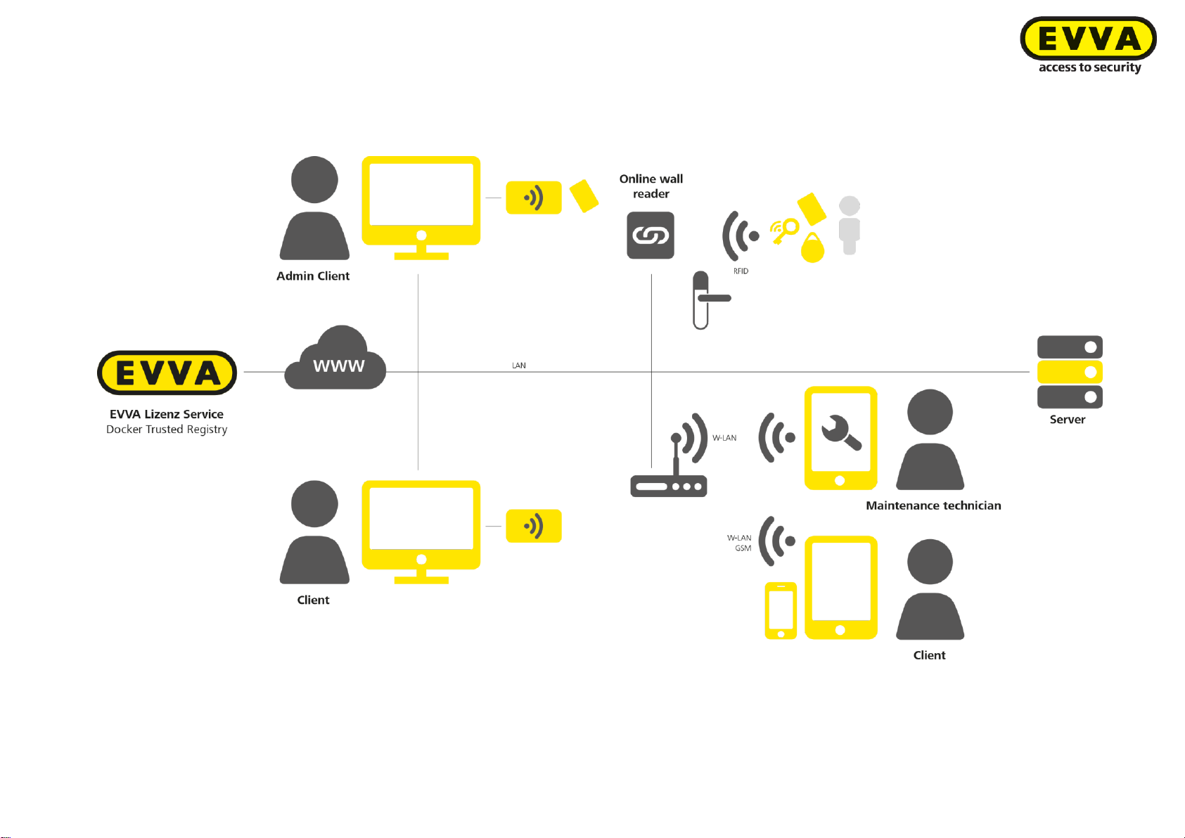
47
KPM.X.Systemhandbuch_X3.0.EN.V1.9 | Subject to misprints and technical changes.
3.3 Attachment to the project checklist
3.3.1 Depiction of layout
Page 48
48
KPM.X.Systemhandbuch_X3.0.EN.V1.9 | Subject to misprints and technical changes.
Service catalogue: Management of a Xesar 3 system
3.4 Service/communication
Application
Service
Network
Default
port
Port ad-
dress
Protocol
TLS
Use
Utilising components
Providing compo-
nents
1;2
Secure Shell (SSH)
LAN/WLAN
22
Configurable
SSH
Yes
Setup and configuration of OS and
Docker Engine
Docker Machine, SSH
client
SSH service (OS)
1;2
Docker Engine API
service
LAN/WLAN
2376
Configurable
HTTP
Yes
Setup the container and volumes
Docker Client
Docker Engine
(Docker, OS)
1;2
Message broker
LAN/WLAN
1883
Configurable
MQTT
Yes
Asynchronous Xesar system interface
Installation manager
Message broker
1;2
Service for the management of security
information
LAN/WLAN
8200
Configurable
HTTP
Yes
Repository for security information,
passwords, keys
Installation manager, installations management
Vault
3
Docker Trusted Registry sfw.evva.com
WAN
443, 4443
443, 4443
HTTP
Yes
Provision of signed Docker images
and verification of the signature
Docker Client, Docker
Engine
Docker Trusted Registry (container image
delivery)
4
Licence service licence.evva.com
WAN
8072
8072
HTTP
Yes
Register an installation/admin card
and loading of key credit codes
Installation manager
Licence service
5
Admin Card terminal
USB
Fix
_
ISO 14443
_
Reading and writing of identification
media
Installation management via the periphery
manager (proxy only)
Coding station
6
Installation management, frontend web
service
LAN/WLAN
8080
Configurable
HTTP
Yes
Web service and delivery of the web
application for the browser
Browser-based
7
Online dealership
components
LAN/WLAN
9081
Configurable
NWP
Yes
Communication with the Xesar software.
Xesar online wall reader
Online component
dealership
Applications
Admin PC mit installation manager: 1: System start; 2: System stop; 3: System update; 4: Licence service (load KeyCredits); 5: with coding station for
Admin Card;
Client PC: 5 Coding station for identification media Client PC Browser/Communication;
Online wall reader: 7 Online wall reader communication
Page 49
49
KPM.X.Systemhandbuch_X3.0.EN.V1.9 | Subject to misprints and technical changes.
Service catalogue: Server and workstations in multi-user system
3.5 Communication, Client PC - Server (backend)
Service
Network
Default
port
Port ad-
dress
Protocol
TLS
Use
Utilising components
Installation management,
frontend web service
LAN/WLAN
8080
configurable
HTTP
Yes
Web service and delivery of the web application for the browser
Browser-based
Message broker*
LAN/WLAN
1883
configurable
MQTT
Yes
Asynchronous Xesar
system interface
Periphery manager
Coding station*
USB
fix
_
ISO 14443
_
Reading and writing of
identification media
Installation management via
the periphery manager (proxy
only)
*Only with Client PC with coding station
Service catalogue: Connection of online wall reader to Xesar 3 system
3.6 Communication, Online wall reader – Server (backend)
Service
Network
Default
port
Port ad-
dress
Protocol
TLS
Use
Utilising com-
ponents
Providing compo-
nents
Online dealership components
LAN/WLAN
9081
configurable
NWP
Yes
Communication
with the Xesar
software.
Xesar online
wall reader
Online component
dealership
Page 50
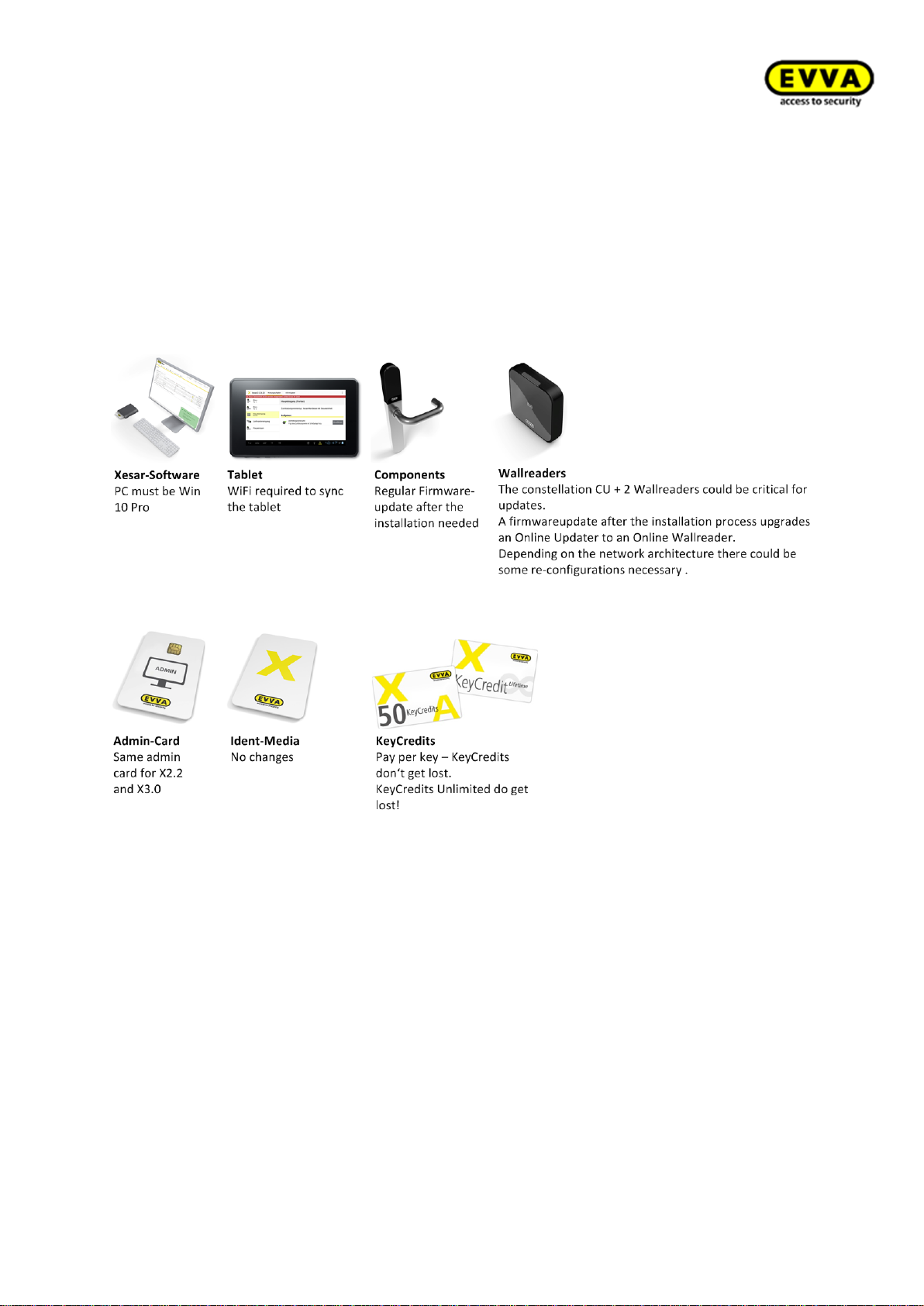
50
KPM.X.Systemhandbuch_X3.0.EN.V1.9 | Subject to misprints and technical changes.
4 System installations, upgrade and
updates
4.1 Upgrade from Xesar 2.2 to Xesar 3.0
Figure 25 – Important information for a software upgrade
Page 51
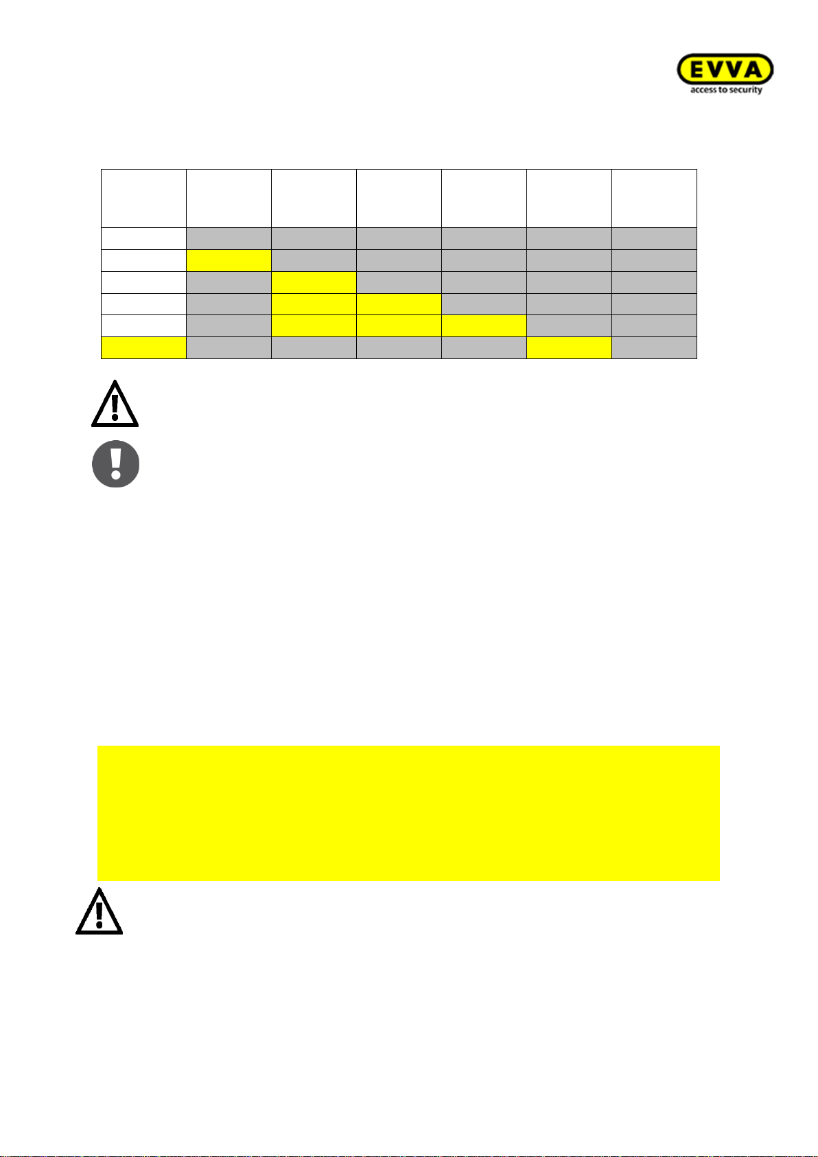
51
KPM.X.Systemhandbuch_X3.0.EN.V1.9 | Subject to misprints and technical changes.
4.1.1 Xesar upgrade compatibility
Target/actual
X1.0
X1.1
X2.0
X2.1
X2.2
X3.0
X1.0
X1.1
x
X2.0
x
X2.1
x x
X2.2
x x x
X3.0
x
Exclusively Xesar 2.2 systems can be upgraded to Xesar 3.0!
Valid for firmware and software!
The following Xesar Tablets are supported by Xesar 3.0:
Xesar Tablet V3 (EVVA (Ares F716XM))
Xesar Tablet V2 (Acer Iconia One 7 (B1-770 & B-730HD))
4.1.2 Upgrade instructions for Xesar 2.2 systems to Xesar 3.0
Please note the text fields highlighted in yellow for the upgrade labelled as: "For upgrades
from Xesar 2.2 to Xesar 3.0 only".
For upgrades from Xesar 2.2 to Xesar 3.0 only
Proceed as follows to upgrade the Xesar software from Xesar 2.2 to Xesar 3.0:
• Insert your Admin Card into the slot of the coding station and load the data from
your Xesar 2.2 system (see section 6.1 Xesar Installation Manager, step 8; loading the Admin Card)
• Import your Xesar 2.2 database file when adding a new system.
Attention: The following items are important for an upgrade from Xesar 2.2
to Xesar 3.0:
• For the X2.2 data import, the personal firewall must always allow mounting or it
may not block the required ports.
Page 52
52
KPM.X.Systemhandbuch_X3.0.EN.V1.9 | Subject to misprints and technical changes.
• Uninstall the existing Xesar app on your Xesar tablet and install the new Xesar 3.0
app. See section: 3.10 Manually uninstalling and installing the Xesar app (upgrade
from Xesar 2.2 to Xesar 3.0)
• The current access component firmware for Xesar 3.0 is transferred to components
with the Xesar tablet and the current Xesar app.
• You can continue to use any available identification media. For this purpose, you
must update them at the coding station or an online wall reader.
• Prior to importing a Xesar 2.2 system to a Xesar 3.0 system it is necessary to enable
the "C drive" for Docker.
• A version 2.2 system can exclusively be imported to and operated in the same
time zone.
• You can continue to use the available Admin Card of your Xesar 2.2 system.
• You can continue to use unit-based KeyCredits. It is not possible to continue to
use KeyCredits Unlimited for Xesar 3.0! Use KeyCredit Xesar Lifetime for unlimited use and pay only once!
• Xesar Lifetime licence must only be redeemed after having updated to Xesar 3.0.
DO NOT redeem in Xesar 2.2 (i.e. not prior to exporting/importing to Xesar 3.0!)
• Two wall readers with one control unit (CU): If you use the "two wall readers
with one control unit" setup in your Xesar 2.2 system, these wall readers must be
removed from the system and set to construction mode prior to the upgrade to
Xesar 3.0. Once again reinstall the two wall readers into the system after having
upgraded to Xesar 3.0.
• If a Xesar 2.2 system with a "fire brigade" authorisation profile is imported into
Xesar 3.0, it may happen that a further fire brigade authorisation profile is generated in 3.0. In this case, one fire brigade profile must be removed manually.
• After having imported a Xesar 2.2 system to Xesar 3.0, EVVA components must
no longer be synchronised with the Xesar 2.2 system. After you have made a
successful import you must consistently work with Xesar 3.0 from then on.
Contact our colleagues from the technical office if you need help or require further
information.
Page 53
53
KPM.X.Systemhandbuch_X3.0.EN.V1.9 | Subject to misprints and technical changes.
4.2 Preparation of the PC for the Xesar 3.0 Installation
Before installing Xesar 3.0, Docker and the coding station driver must be installed on the
system PC (with Windows 10 Pro).
4.2.1 Docker installation
Docker is an open source software designed to isolate applications with container visualisation. You must initially install Docker on your PC.
IMPORTANT:
Docker CE for Windows can only be installed on PCs with Windows 10 Pro from
version 1511 (build 10586). If you have not installed the required Windows 10 Pro
version, run a Windows 10 Pro update.
4.2.1.1 Download Docker
IMPORTANT:
• The current version Docker version release is Docker Community Edition
18.06.1-ce-win73 2018-08-29
• For more recent versions, please contact your EVVA Technical Office prior to in-
stallation.
• If you reinstall Docker (Uninstall Docker and then reinstall it), all system data will
be lost. This is why all containers musk be backed up before Docker is uninstalled. This can be done as of version Xesar 3.0 SP1 with the manual or auto-
matic backup function in the Installation Manager.
• Before a Docker update, the Xesar system must be stopped in the Installation
Manager.
• After importing a Xesar 2.2 system, the identification media must be updated.
1. Step: Download Docker to your computer:
https://docs.docker.com/docker-for-windows/release-notes/
Docker version: Docker Community Edition 18.06.1-ce-win73 2018-08-29
Page 54
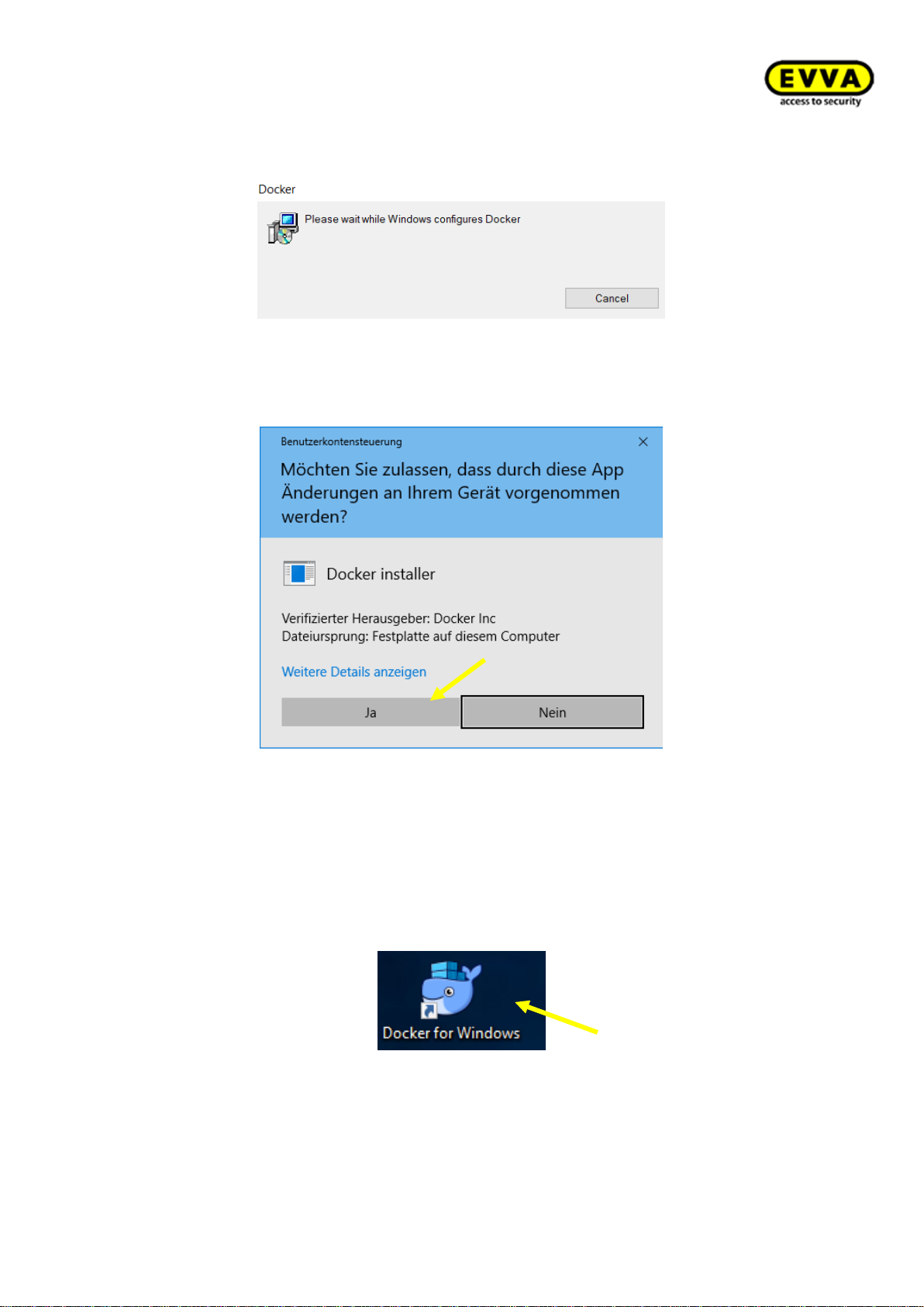
54
KPM.X.Systemhandbuch_X3.0.EN.V1.9 | Subject to misprints and technical changes.
4.2.1.2 Docker installation steps
1. Step: the installer automatically opens after the download.
Figure 26 – Installing Docker
Click "Yes" if a Windows warning message appears.
Figure 27 – Installing Docker security notice
2. Step: Starting Docker
a. The "Docker is starting…" status message automatically opens in the Windows
task bar.
b. If this is not the case, double-click the "Docker for Windows" link on your desk-
top.
!!Start may take a few minutes!!
Figure 28 – Starting Docker
Page 55
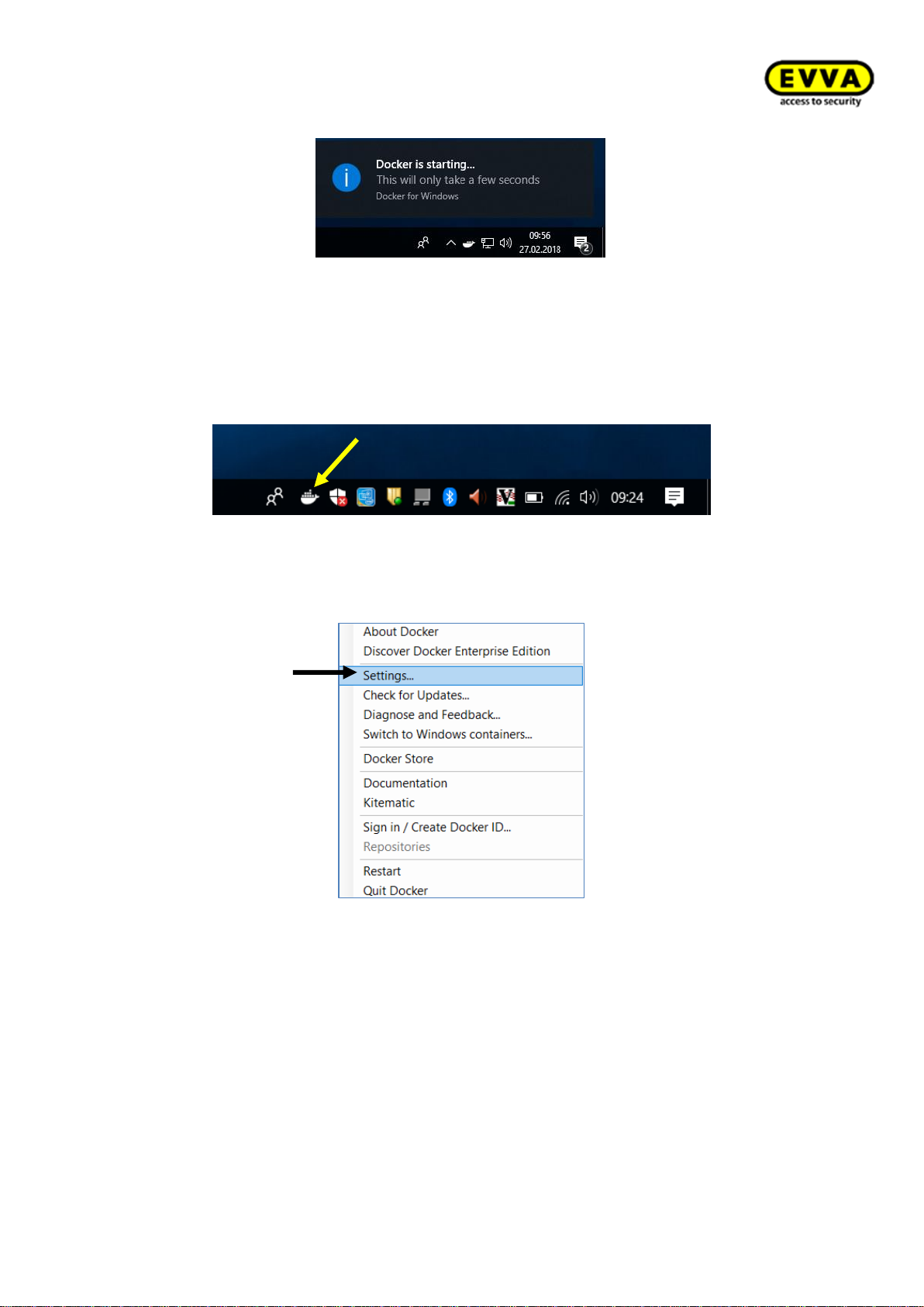
55
KPM.X.Systemhandbuch_X3.0.EN.V1.9 | Subject to misprints and technical changes.
Figure 29 – Docker starting progress
3. Step: "Docker is now up and running!"
a. Once Docker has started a status window with the following message opens:
"Docker is now up and running!".
b. The status window closes automatically.
c. Right-click the Docker icon to open the settings.
Figure 30 - Docker status windowtime
4. Step: click "Settings…".
Figure 31 – Docker settings
Page 56
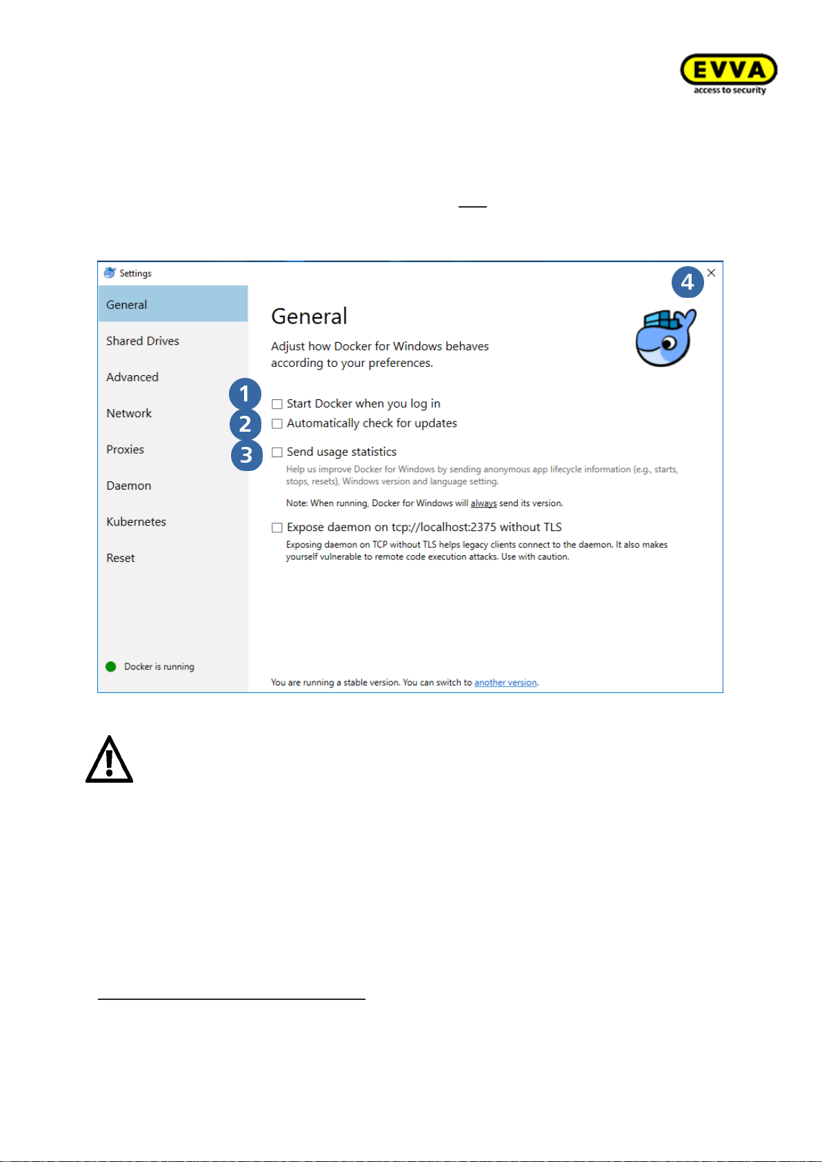
56
KPM.X.Systemhandbuch_X3.0.EN.V1.9 | Subject to misprints and technical changes.
5. Step: Checking the settings
a. Make sure the following items have been activated: "Start Docker when you log
in"
b. "Automatically check for updates"
c. Do not „Send usage statistics“ that are not confirmed
d. You may now close Docker's general settings with "X".
Figure 32 – Docker settings selection
Attention:
The PC must support "Hyper-V Virtualisation" and this feature must have
been activated to use Docker!
The certificates for connections between containers/services are valid for one year. They
expire if a system has not been started for an unusually long period of time (> 1 year)
using the Xesar Installation Manager. In this process, malfunctions and error messages
may appear in the Xesar software. In this case the certificates are renewed upon starting
for the first time. The status automatically regenerates after a few minutes.
Docker has now been installed on your PC! In the next step install the driver for
the coding station!
If Hyper-V has not been activated: enter "Windows Features" in the command line.
Click activate or deactivate Windows features.
Page 57
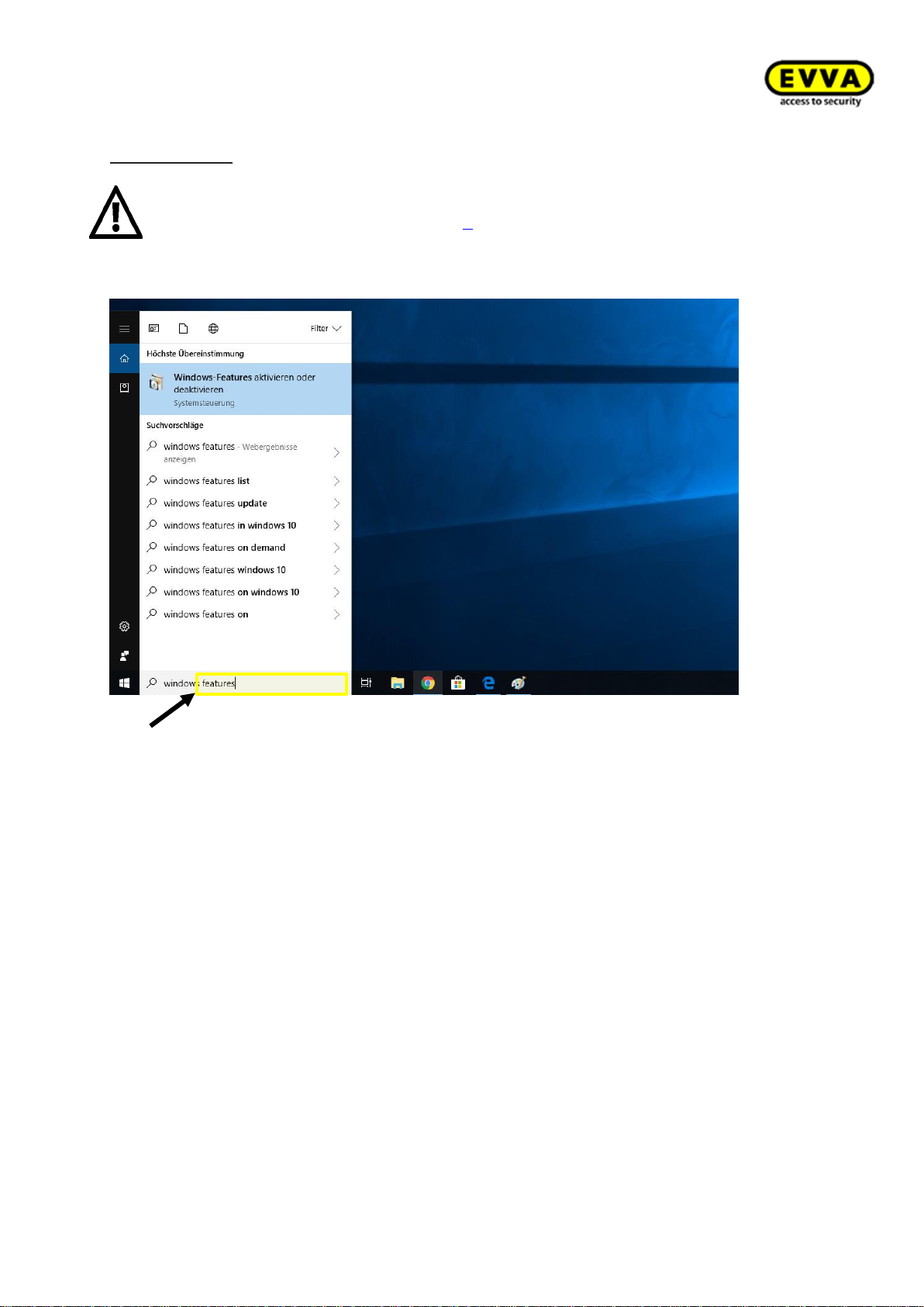
57
KPM.X.Systemhandbuch_X3.0.EN.V1.9 | Subject to misprints and technical changes.
Attention:
With a new installation of Docker (uninstall Docker and then reinstall it), all
system data will be lost. This means that all files must be secured before
Docker is deinstalled. (See section 6 Securing the Xesar system data in the
Installation Manager)
Figure 33 - Windows features
Scroll down to "Hyper-V" and activate it. Then click "OK".
Page 58
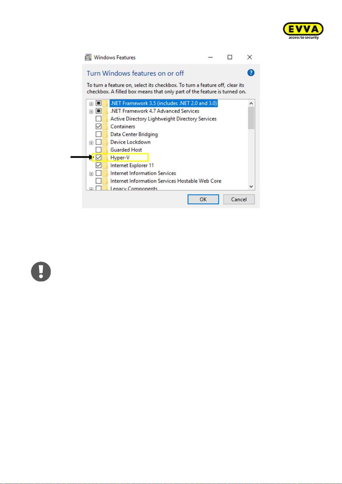
58
KPM.X.Systemhandbuch_X3.0.EN.V1.9 | Subject to misprints and technical changes.
Figure 34 – Activating Hyper-V
4.2.2 Coding station driverinstallation
The HID hardware driver is required to operate the Xesar coding station (HID Omnikey 5421) on the PC. A driver installation is not necessary if you already use coding
station version HID Omnikey 5422! You can directly continue with section 5 Xesar
3.0 - Programs
Two driver installation types are possible:
• Automatic driver search in Windows
• Manual driver search directly on the manufacturer's homepage
4.2.2.1 Automatic driver search via Windows
Please use the Windows Device Manager to install the coding station's driver.
1. Step: Plug your coding station in the USB connection of your PC without
Admin Card!
2. Step: Use the Windows search bar to open the Device Manager.
Page 59
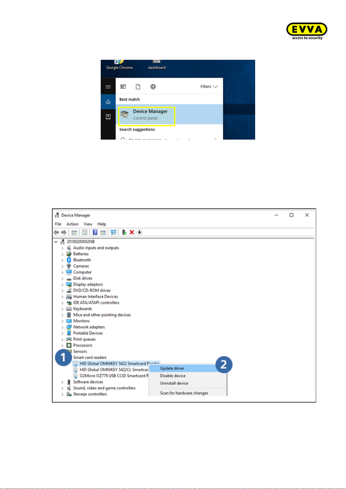
59
KPM.X.Systemhandbuch_X3.0.EN.V1.9 | Subject to misprints and technical changes.
Figure 35 – Windows Device Manager
3. Step: Search the list for "Smart card readers" (potentially "Readers"). Click
this entry and select the entry starting with "Microsoft…". Right-click the "Microsoft…" entry and select "Update driver".
Figure 36 – Updating the Microsoft driver
Page 60
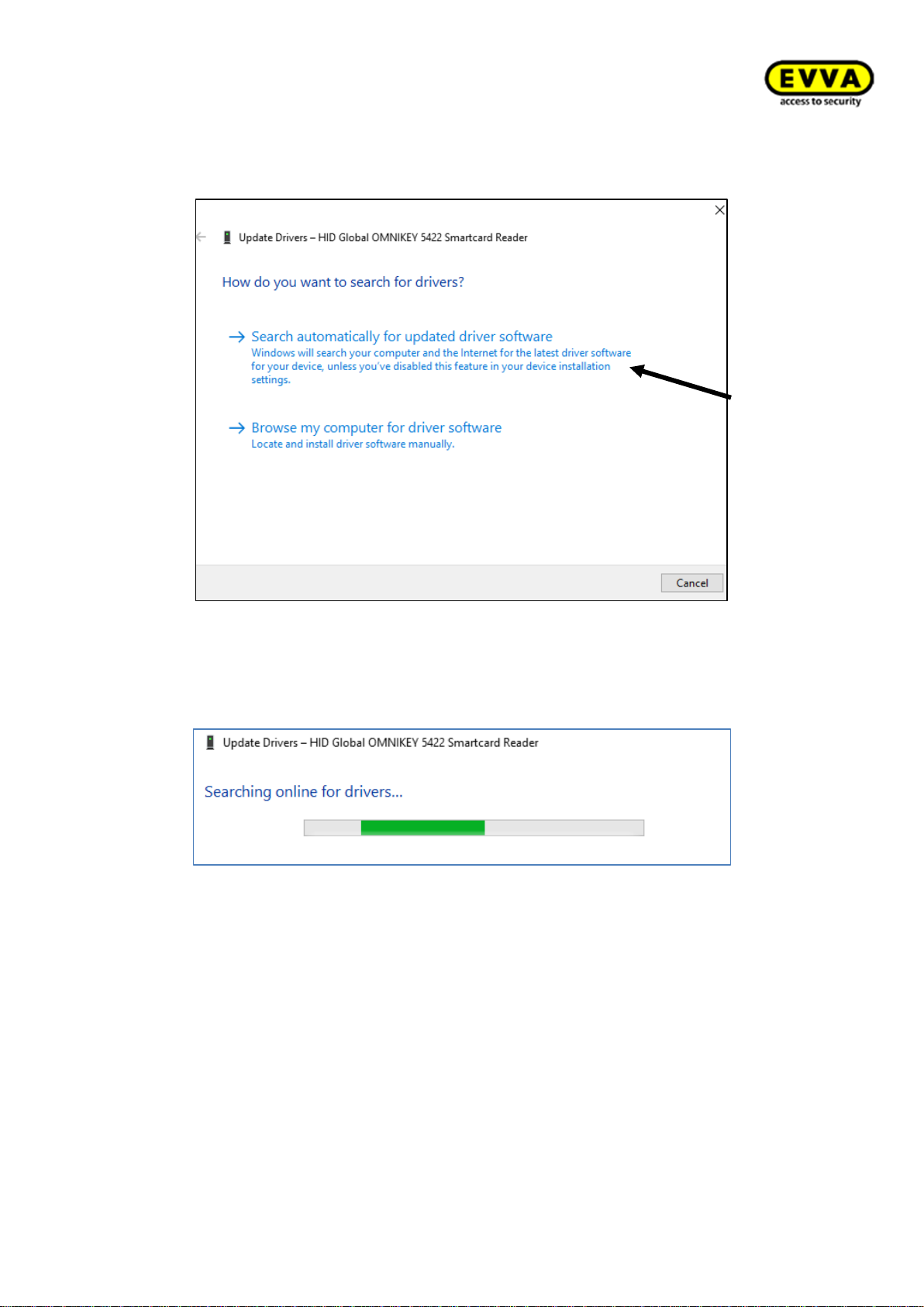
60
KPM.X.Systemhandbuch_X3.0.EN.V1.9 | Subject to misprints and technical changes.
4. Step: Windows prompts you whether to "Automatically search for updated driver
software". Please click this option.
Figure 37 – Driver search
5. Step: the driver will now be automatically downloaded and installed by Windows
Device Manager!
Figure 38 – Coding station – automatic driver installation
Page 61
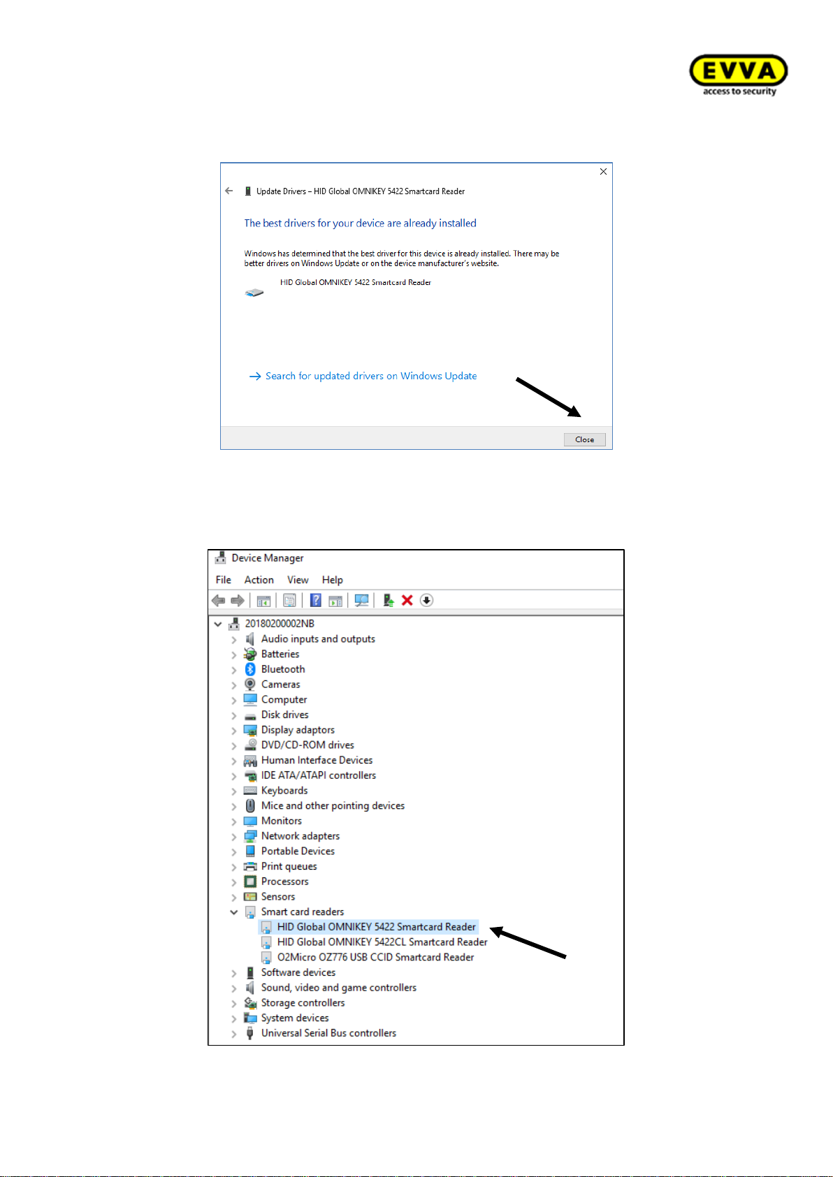
61
KPM.X.Systemhandbuch_X3.0.EN.V1.9 | Subject to misprints and technical changes.
6. Step: the driver has been installed. Click "Close".
Figure 39 – Coding station – successful driver installation
The reader used is now listed in the Device Manager. In this case: Omnikey 5422
Figure 40 – display of the coding station in the Device Manager
Page 62
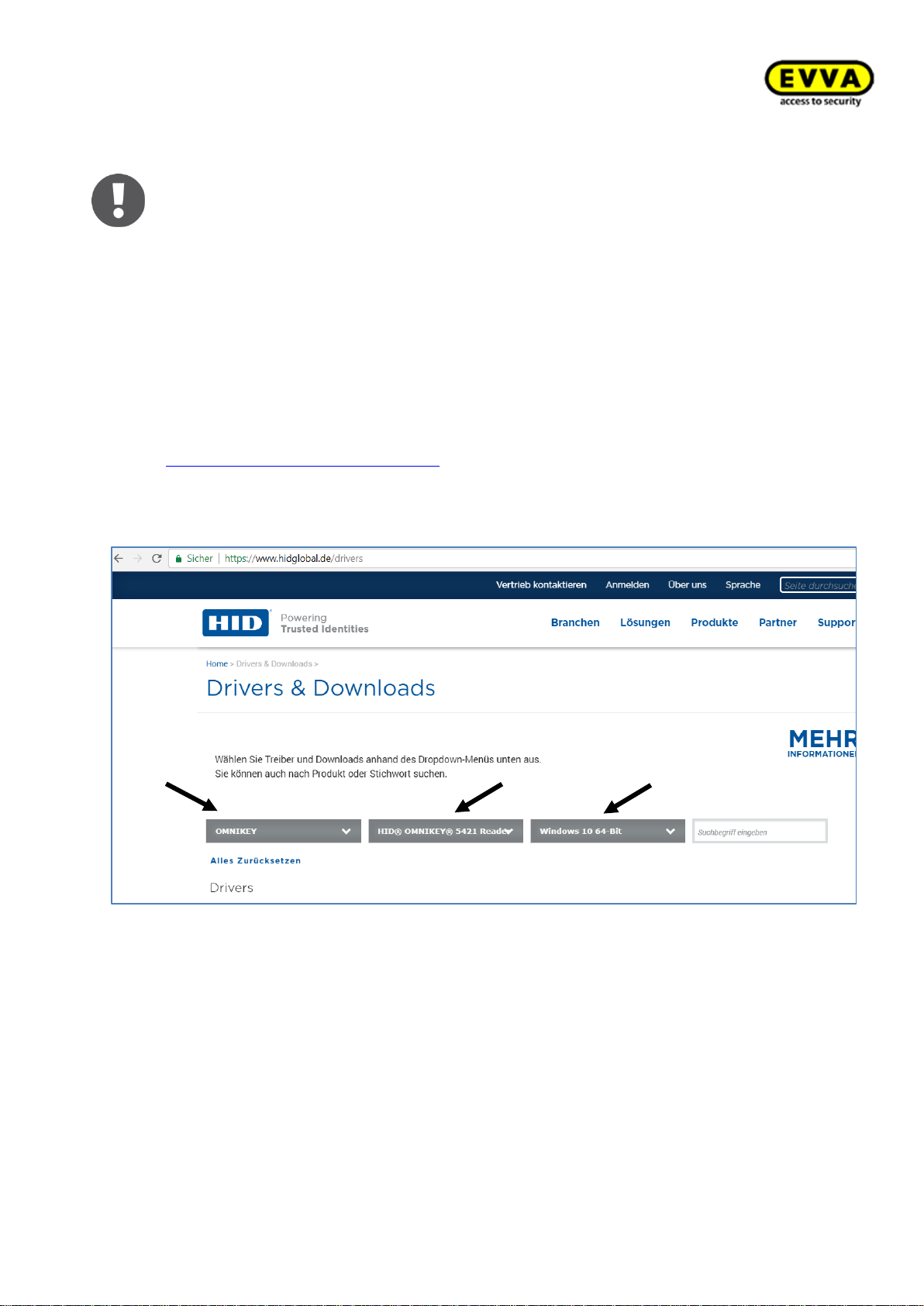
62
KPM.X.Systemhandbuch_X3.0.EN.V1.9 | Subject to misprints and technical changes.
The coding station driver has been installed. Please skip to section: 5 Xesar
3.0 - Programs, to continue the Xesar software installation.
4.2.2.2 Alternative: Manual driver search and HID driver installation
Alternatively you can also manually search for the the driver and download it from the
HID GLOBAL page.
1. Step: Check the model type of your Omnikey coding station on the reverse side
(e.g.: HID OMNIKEY 5422) and connect the coding station to your PC.
2. Step: On the HID GLOBAL website, go to the Drivers section
https://www.hidglobal.com/drivers or search for „HID Global Drivers“ in Google.
For "Brand" select: "OMNIKEY" and enter the model of your coding station in "AllProducts, e.g. "HID OMNIKEY 5421" and select your operating system in "AllOS":
Windows 10 64 bit
Figure 41 – Coding station download page
Page 63
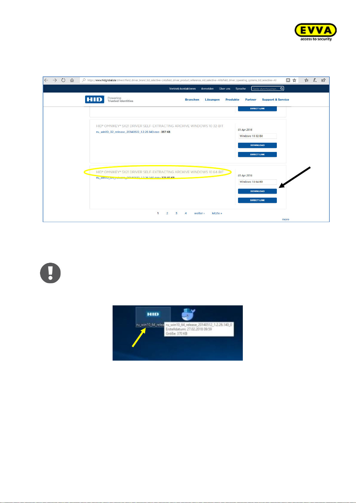
63
KPM.X.Systemhandbuch_X3.0.EN.V1.9 | Subject to misprints and technical changes.
3. Step: Scroll to the Windows 10 Pro driver designated as "SELF-EXTRACTING AR-
CHIVE".
Figure 42 – Coding station download package
You may see a warning message regarding EULA, please accept it!
Click "Run" in the browser to directly open the file and start the process – consequently skip the next step in these instructions.
4. Step: double-click the file.
Figure 43 – Coding station – driver installation application
Page 64
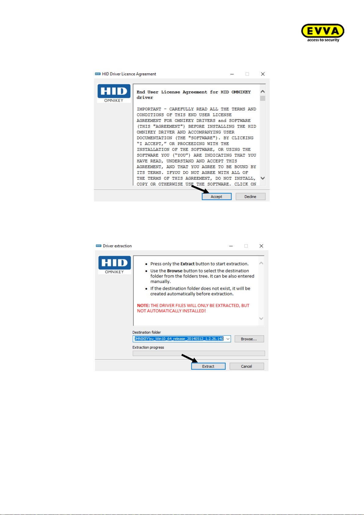
64
KPM.X.Systemhandbuch_X3.0.EN.V1.9 | Subject to misprints and technical changes.
5. Step: click "Accept" to continue the installation.
Figure 44 – Coding station driver installer 1
6. Step: click "Extract" to install the driver.
Figure 45 – Coding station driver installer 2
You have now successfully installed the HID driver!
Page 65
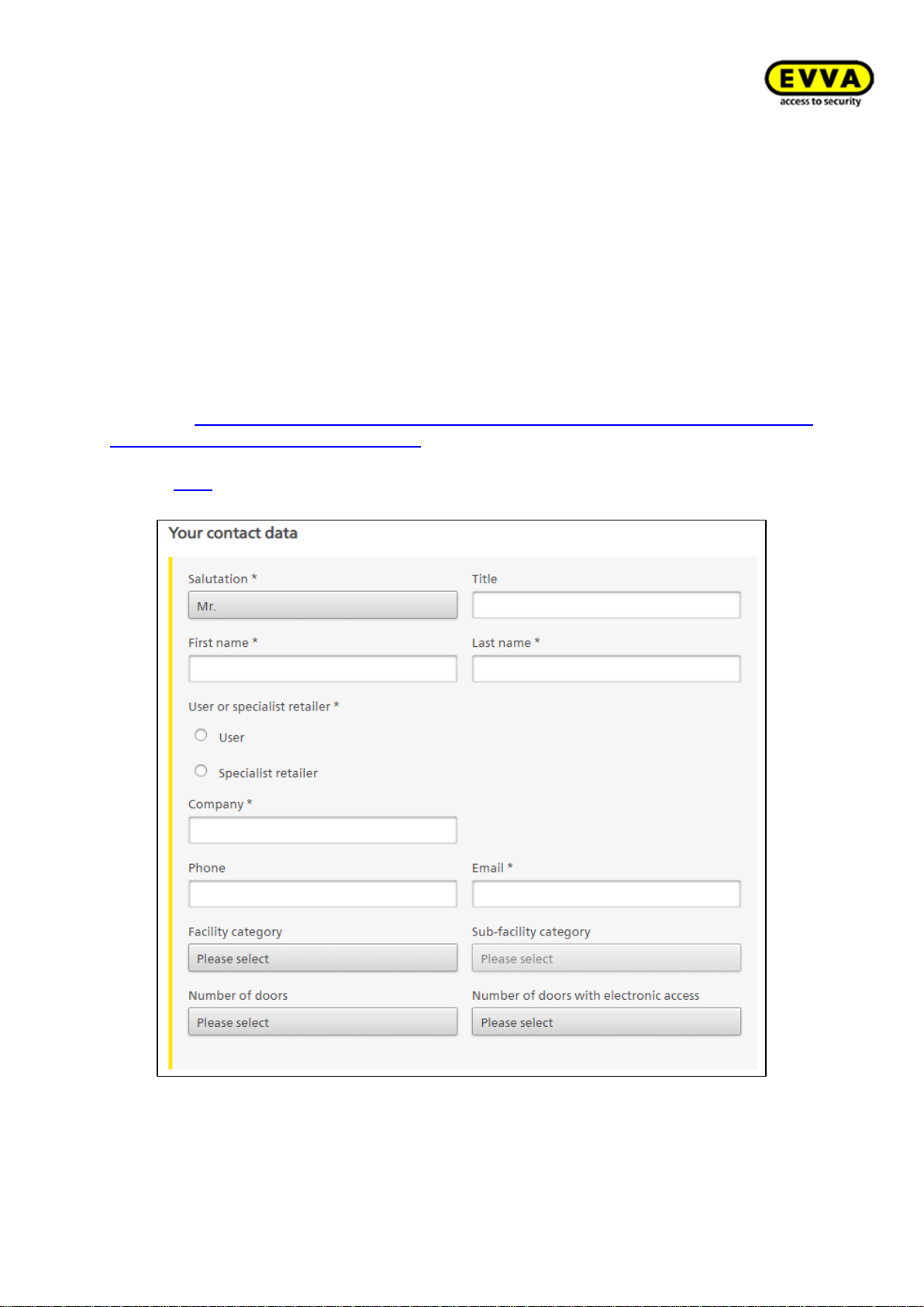
65
KPM.X.Systemhandbuch_X3.0.EN.V1.9 | Subject to misprints and technical changes.
5 Xesar 3.0 - Programs
The following two programs are also necessary in addition to the Xesar software to manage
the Xesar system:
• Xesar Installation Manager: for starting and stopping the server, managing the
Admin Card, updating the software, managing several systems, redeeming
KeyCredits and KeyCredit Xesar Lifetime licences.
• Xesar Periphery Manager: enables operation of the coding station on the client
computer. Download the Periphery Manager in the Xesar 3.0 software in the "Support/update" tile.
The download for the Xesar-Software (Installation Manager) can be found at our EVVA
Website: https://www.evva.com/uk-en/products/electroniclockingsystemsaccesscontrol-
systems/xesar/xesarsoftwaredownload/
Or click here to directly access the following download request form.
Figure 46 – Xesar download form
Page 66
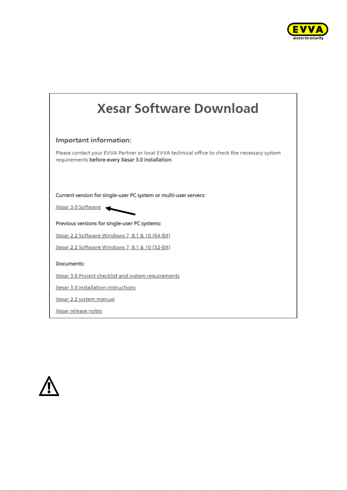
66
KPM.X.Systemhandbuch_X3.0.EN.V1.9 | Subject to misprints and technical changes.
You will receive an email with a temporary download link! Click the link and the following
window opens.
Figure 47 – Download Installation Manager for software
Download the file!
Attention:
The download of the Installation Manager may take up to 2 minutes!
Page 67
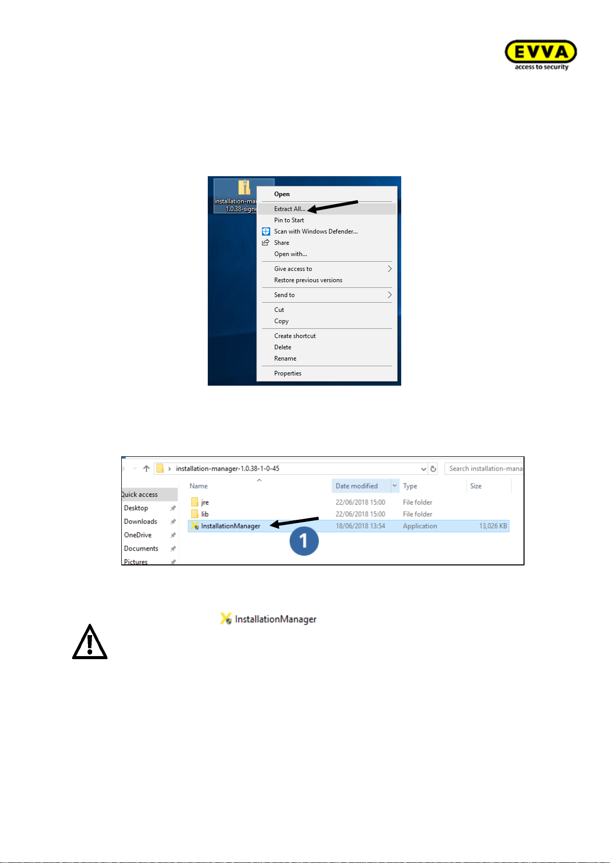
67
KPM.X.Systemhandbuch_X3.0.EN.V1.9 | Subject to misprints and technical changes.
5.1 Xesar Installation Manager
1. Step: right-click to unpack the ZIP file. Select "Extract all". The system creates a
new, unzipped folder with the same name.
!!Unpacking may take a while!!
Figure 48 - Xesar Installation Manager ZIP file
2. Step: Double-click to open the new folder and the application.
Figure 49 – Installation Manager application
The application file may not be removed from the file or displaced. However, you can create a shortcut on the desktop and start the Installation Manager from there.
The Installation Manager must be started from a local drive and not from a network
drive.
Page 68
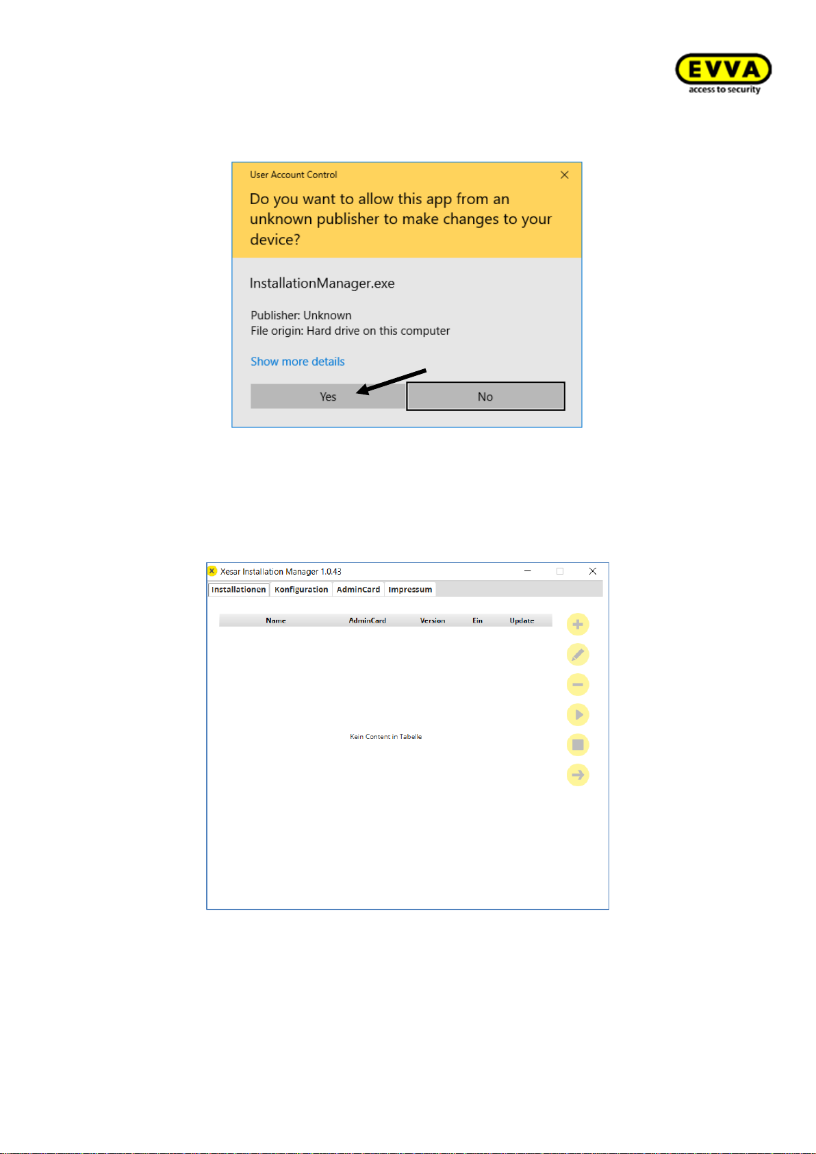
68
KPM.X.Systemhandbuch_X3.0.EN.V1.9 | Subject to misprints and technical changes.
The following warning may appear. Please click "Yes".
Figure 50 – Installation Manager warning message
3. Step: Xesar Installation Manager opens.
Figure 51 – Installation Manager window
Page 69
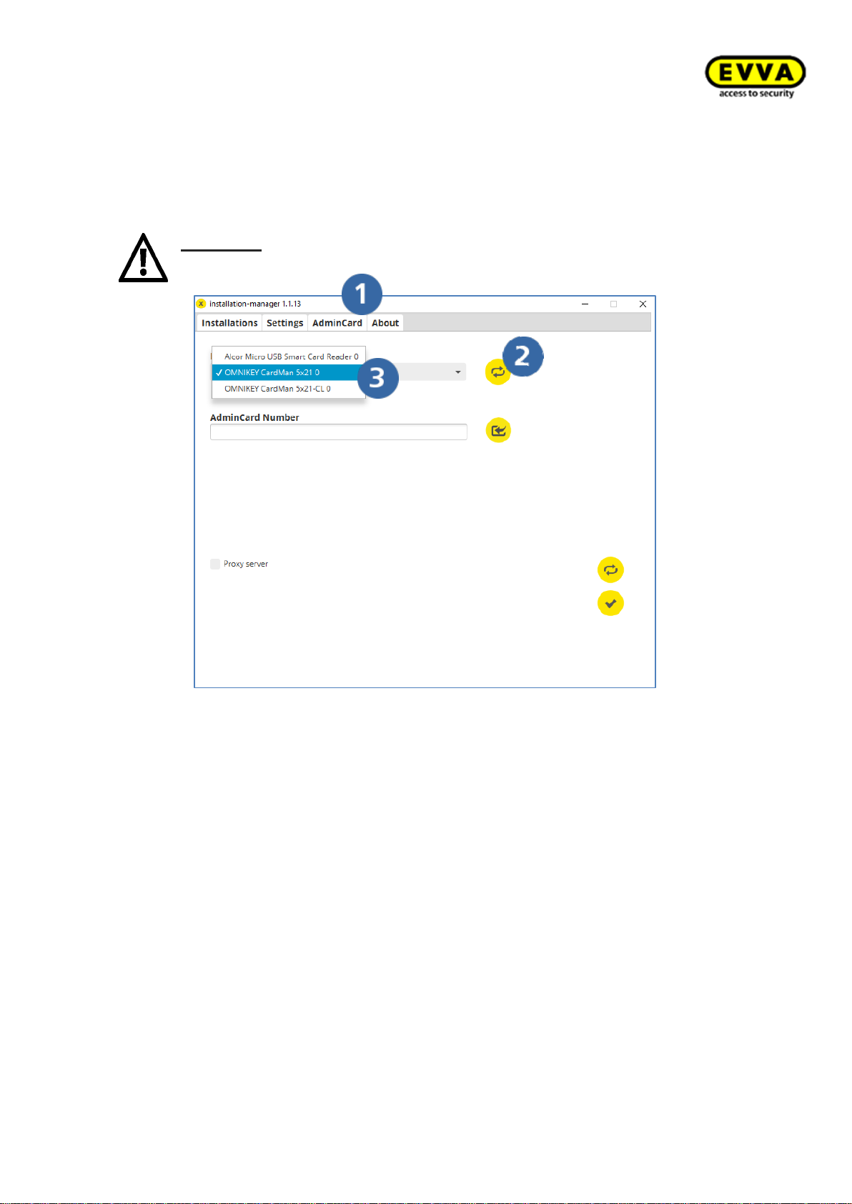
69
KPM.X.Systemhandbuch_X3.0.EN.V1.9 | Subject to misprints and technical changes.
4. Step: Load reading unit in the Installation Manager
a. Click the "Admin Card" tab.
b. The coding station can read and process contact-based media (Admin Card) and
contactless CL (all Xesar identification media) smart cards. The contact-based
reader is only required for the Installation Manager and reading the Admin Card.
Attention: If synchronisation fails, select the contact-based reader (see
following screenshot) via the drop-down menu.
Figure 52 – Installation Manager tab: Admin Card
Page 70
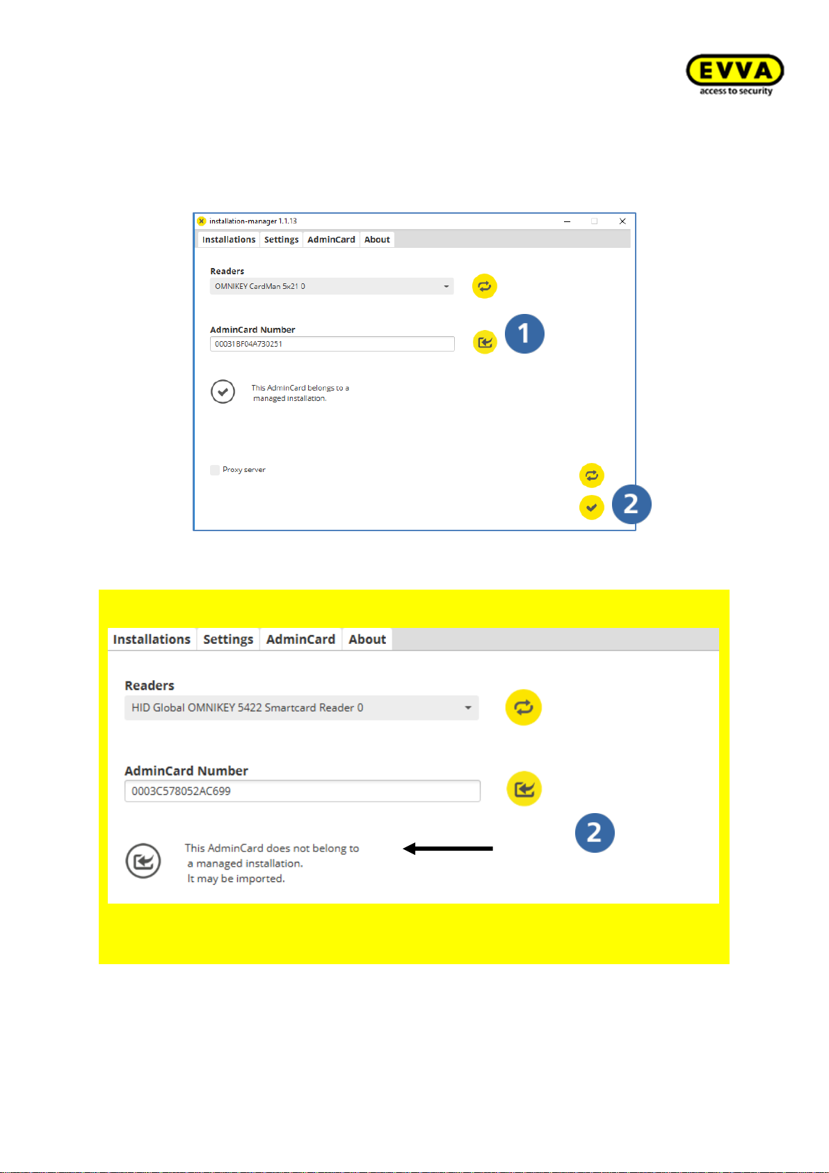
70
KPM.X.Systemhandbuch_X3.0.EN.V1.9 | Subject to misprints and technical changes.
5. Step: Loading the Admin Card
a. Insert the Admin Card into the slot of the coding station and
b. click the "Load" icon.
c. Click the "Save" icon to save.
Figure 53 – Installation manager tab: Admin Card – loading the card
For UPGRADES from Xesar 2.2 to Xesar 3.0 only
• Insert the Admin Card of your Xesar 2.2 system in the coding station
The following is displayed. You can now import Xesar 2.2 data.
Figure 54 – Installation Manager Admin Card import
Page 71
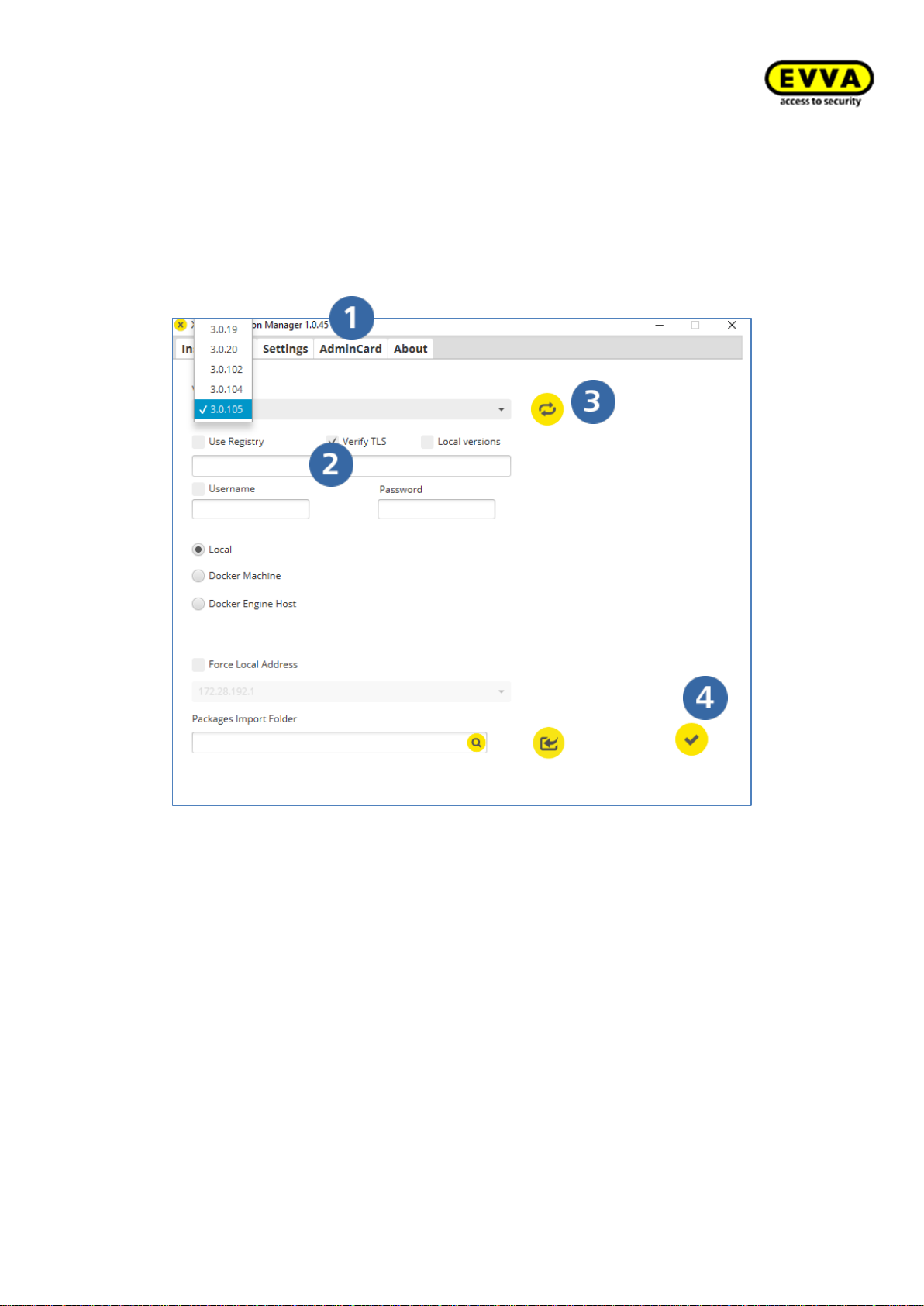
71
KPM.X.Systemhandbuch_X3.0.EN.V1.9 | Subject to misprints and technical changes.
6. Step: Loading the most recent Xesar version
a. Click the Settings tab.
b. Confirm "Check TLS".
c. Click "Synchronise".
d. The most recent version is automatically loaded and selected for you. Select "Ver-
sion" from the drop-down menu to check this and click "Save".
Figure 55 – Installation Manager tab: Configuration
Page 72
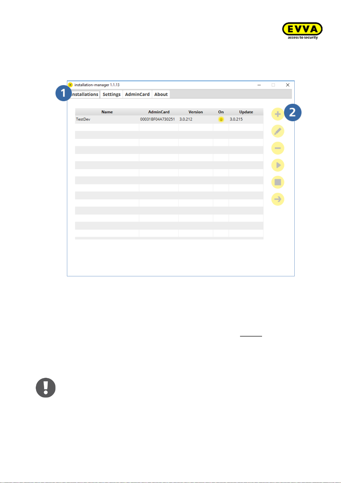
72
KPM.X.Systemhandbuch_X3.0.EN.V1.9 | Subject to misprints and technical changes.
7. Step: Creating a new system
a. Click the "Installations" tab and
b. Click "+".
Figure 56 - Installation Manager, create new system
8. Step: System specifications
a. Enter a system name (with the exception of $ and “special characters can be
used), an additional description can also be added.
b. (the registered ports must be available in the system) and the "Local" default
option must be selected.
c. Select your time zone from the drop-down menu. You cannot subsequently
change this!
d. Select the backup path for data backup.
e. Select the settings for automatic backups.
f. Click "Confirm" to initialise the installation process.
The process may take a few minutes!
Page 73

73
KPM.X.Systemhandbuch_X3.0.EN.V1.9 | Subject to misprints and technical changes.
Figure 57 – Installation Manager system specification
Notice: write down the web port. You will need it later to configure the Xesar
tablet!
Page 74
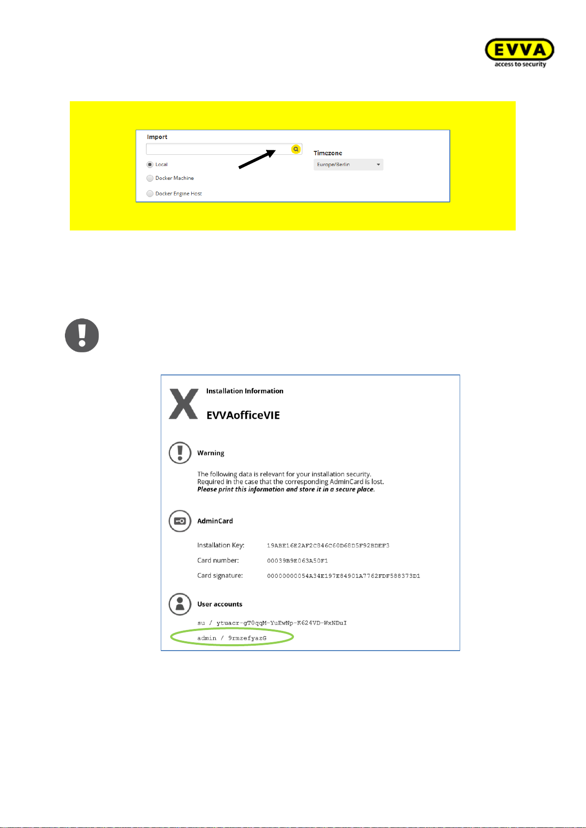
74
KPM.X.Systemhandbuch_X3.0.EN.V1.9 | Subject to misprints and technical changes.
Only for UPGRADES from Xesar 2.2 to Xesar 3.0
Use the "Import" field for the data import of your Xesar 2.2 system. The file name is
"aesssdb.h2" or "aesssdb.h2.db".
Figure 58 – Installation Manager database import
You have then successfully installed a Xesar 3.0 system!
9. Step: installation information: admin + password
After successful installation of the system, an overview sheet which contains the installation information is automatically generated and opened.
It features the installation administrator (admin) and system administrator (su) passwords. Log in with the admin user name and password.
Figure 59 – Installation information
Page 75
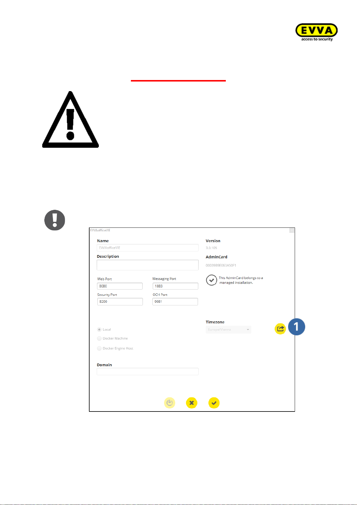
75
KPM.X.Systemhandbuch_X3.0.EN.V1.9 | Subject to misprints and technical changes.
Attention:
In the event of loss or failure of the Admin
Card, the information from the installation
information is absolutely necessary to continue operating the system. Print out this
information and keep it in a safe place!
EVVA will be unable to restore the data if
you lose this information!
If the system information does not automatically open in a pop-up window:
a. Click the Configuration tab and click the "Export" icon
Figure 60 – System information "export"
Page 76
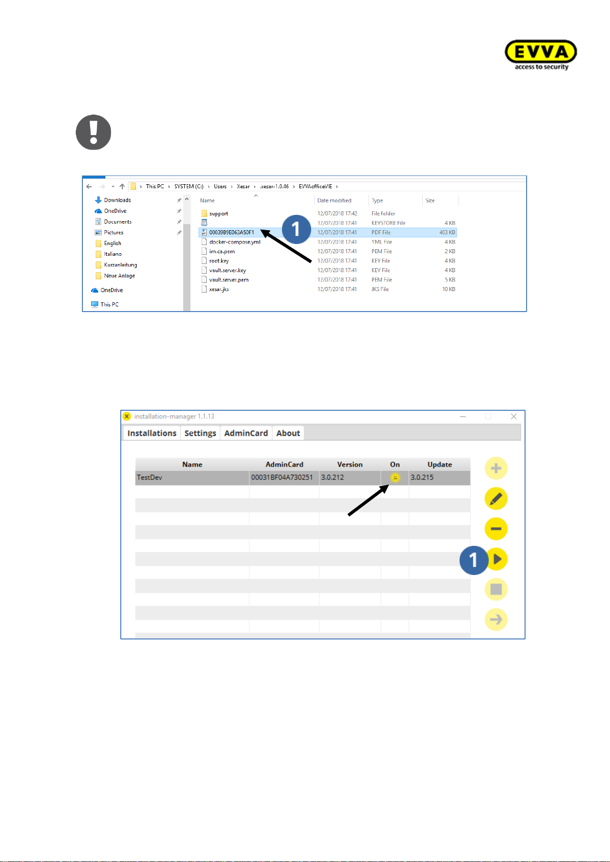
76
KPM.X.Systemhandbuch_X3.0.EN.V1.9 | Subject to misprints and technical changes.
b. Alternatively, the information is available at: C:\Users\Xesar\.xesar-
1.0.43\Anlagenname Open the PDF here
Figure 61 – Alternative system information
10. Step: Starting the system
a. The installation has been completed successfully once the system appears as a
list entry. The "" icon indicates that the software has not been started yet.
b. Highlight the list row for your system and then click the "Start" icon.
Figure 62 – Installation Manager - system not started
Page 77
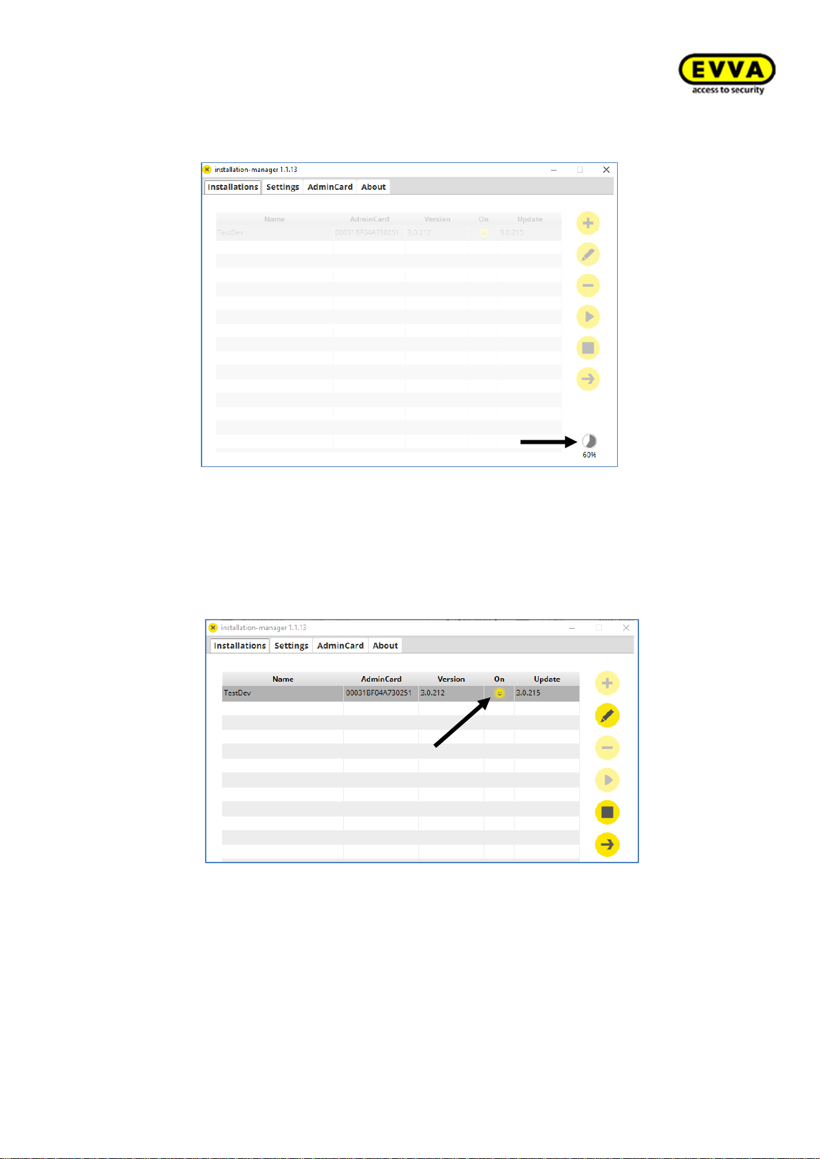
77
KPM.X.Systemhandbuch_X3.0.EN.V1.9 | Subject to misprints and technical changes.
The progress icon indicates that the system is starting.
Figure 63 - Installation Manager, the system loads
11. Step: System running
a. The "☺" icon indicates that the system is running.
Figure 64 - Installation Manager funktionen
Page 78
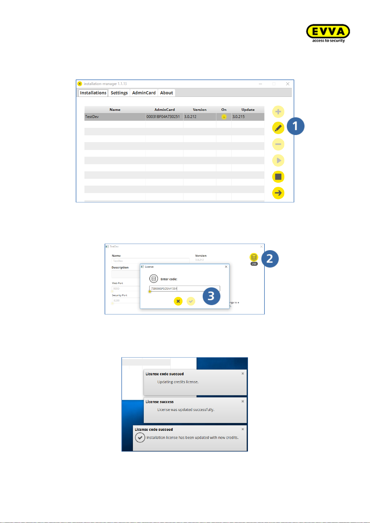
78
KPM.X.Systemhandbuch_X3.0.EN.V1.9 | Subject to misprints and technical changes.
12. Step: Adding KeyCredits
a. Click the edit icon
Figure 65 – Loading/activating KeyCredits
b. Click the "KeyCredits container" icon
c. Enter your KeyCredits code (on the rear of the scratch card) in the field
and click Confirm.
Figure 66 – Entering the KeyCredits code
You will receive the following messages from the EVVA licence server after having successfully loaded KeyCredits:
Figure 67 – Licencing successful
Page 79
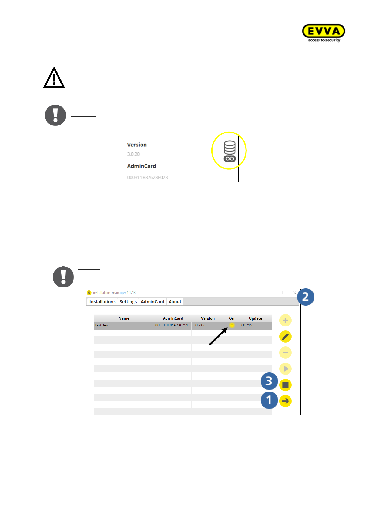
79
KPM.X.Systemhandbuch_X3.0.EN.V1.9 | Subject to misprints and technical changes.
Attention: an active Internet connection to the EVVA licence service is required
to redeem KeyCredits!
Notice: The following appears after having redeemed a KeyCredits Xesar Lifetime
licence:
Figure 68 – KeyCredit Xesar Lifetime
13. Step: Opening the Xesar software dashboard
a. The "☺" icon indicates that the system is running.
b. Click the arrow to open the Xesar dashboard.
c. You can close the Installation Manager. The application will continue to run in
the background.
Notice: Click the "Stop" icon to quite system (server) operation. The Admin
Card must have been inserted in the coding station to start and stop the server!
Figure 69 - Installation Manager funktions
Page 80
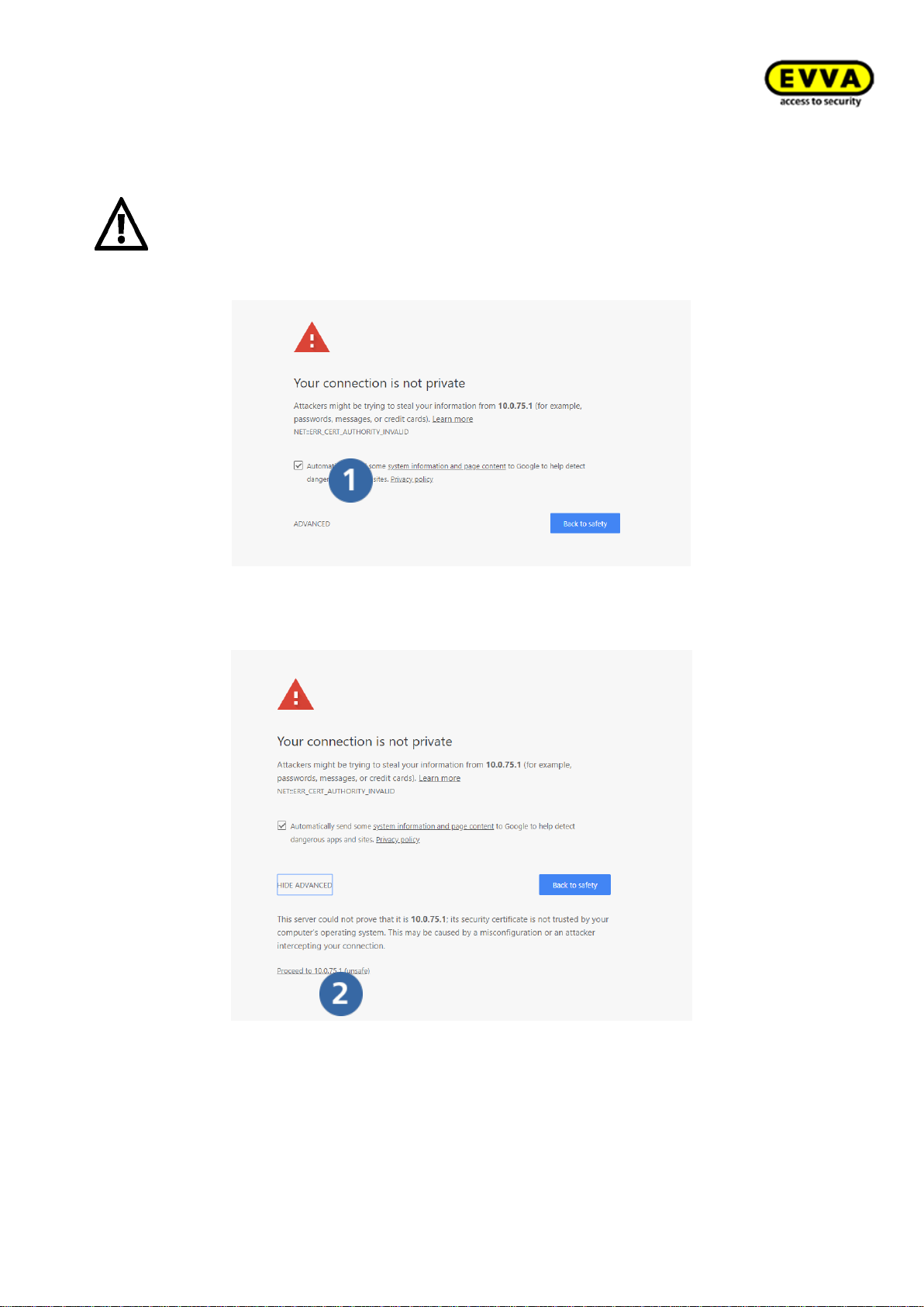
80
KPM.X.Systemhandbuch_X3.0.EN.V1.9 | Subject to misprints and technical changes.
14. Step: Warning from your browser:
a. As soon as Xesar is started with the arrow in the Installation Manager, warnings
will appear in the browser!
Attention: the warnings may differ depending on the browser!
b. Click Details.
Figure 70 – Warning in browser
15. Step: Click on "Load website anyway".
Figure 71 – Warning browser 2
Page 81
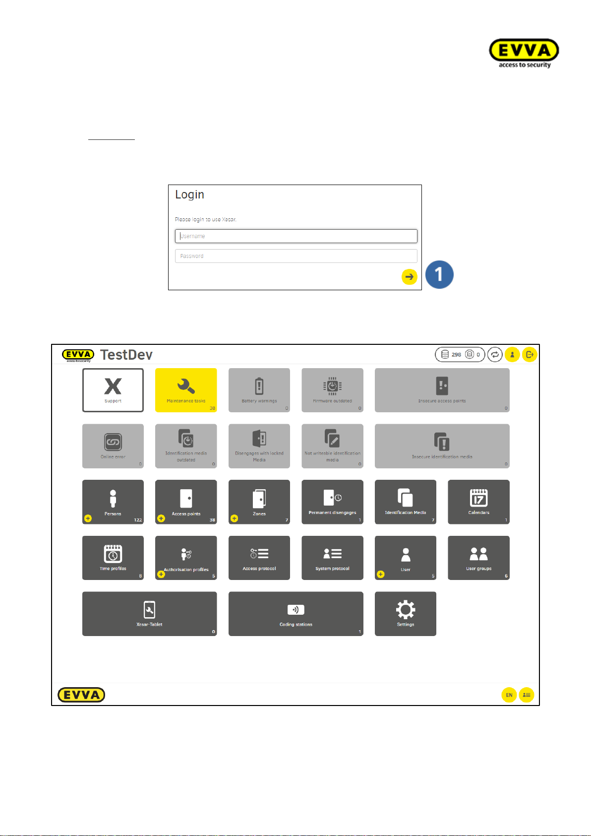
81
KPM.X.Systemhandbuch_X3.0.EN.V1.9 | Subject to misprints and technical changes.
16. Step: Xesar software login:
Log in with the admin user name and password and click the arrow .
Example:
User name: admin
Password: FmJeWgKcFA
Figure 72 - Login window
Figure 73 – Xesar dashboard
Page 82
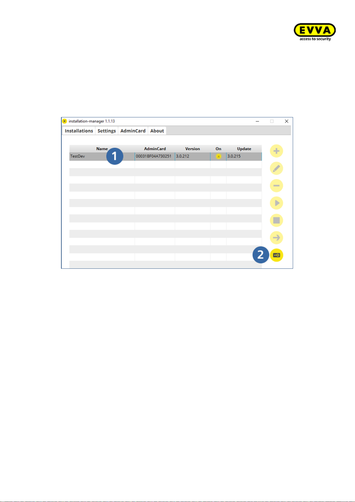
82
KPM.X.Systemhandbuch_X3.0.EN.V1.9 | Subject to misprints and technical changes.
5.2 AdminCard exchange:
If the AdminCard is defective or is lost, then it can be replaced as follows:
• Insert a new AdminCard in the coding station.
• In the Installation Manager, select the desired system (1) and click on the
key button (2).
• In the AdminCard Operations window, select Exchange card and enter the installa-
tion key, card number and card signature from the installation information sheet.
Page 83
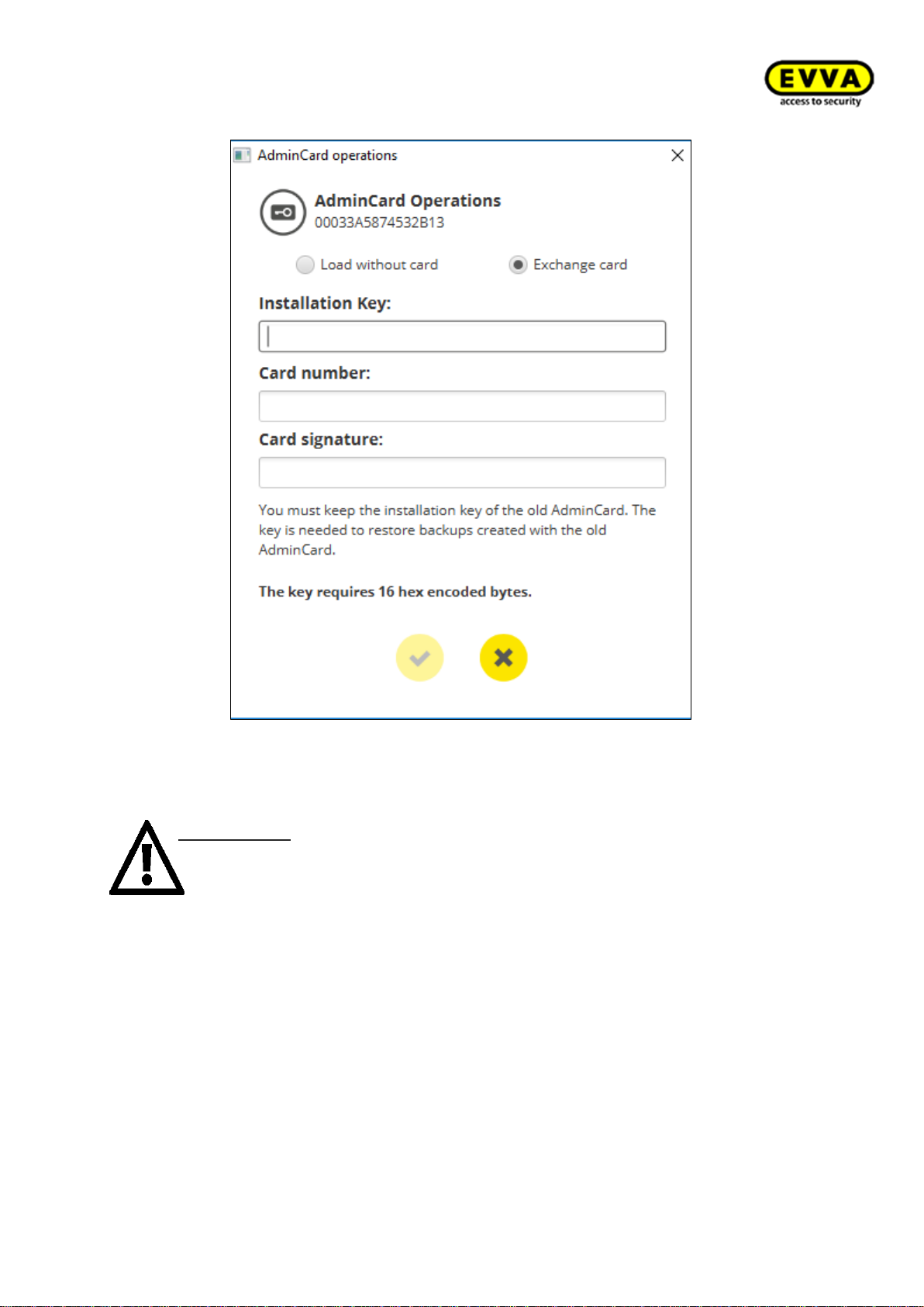
83
KPM.X.Systemhandbuch_X3.0.EN.V1.9 | Subject to misprints and technical changes.
• Upon confirmation, a new installation information sheet will be generated.
• Print this document again and keep it in a safe place.
IMPORTANT: Make sure that you perform a manual backup in the Installation
Manager after the AdminCard exchange. Otherwise, a restore will not fit the
new AdminCard.
Page 84
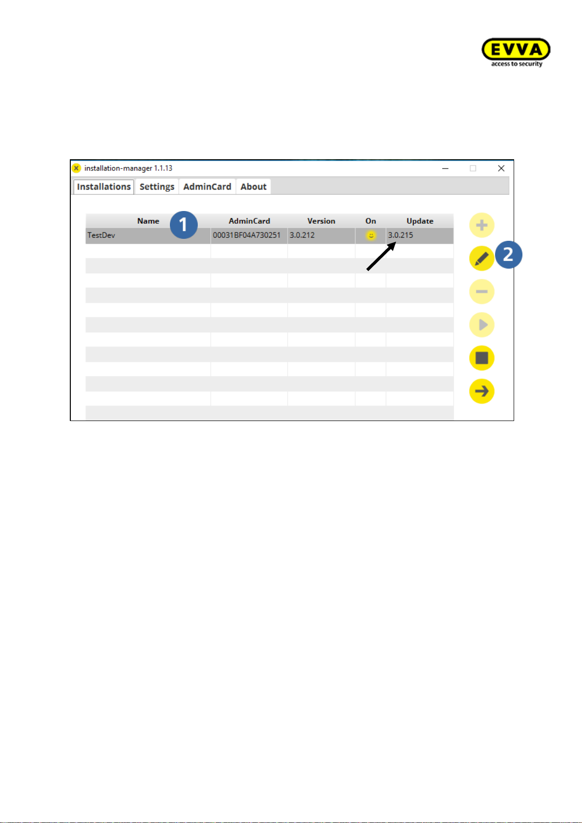
84
KPM.X.Systemhandbuch_X3.0.EN.V1.9 | Subject to misprints and technical changes.
5.3 Software Update
If a new Xesar software version is available, then the new software version will be indicated in the "Update" column in the Installation Manager.
Select the system (1) and click on the edit button (2) to go to the settings page.
Page 85
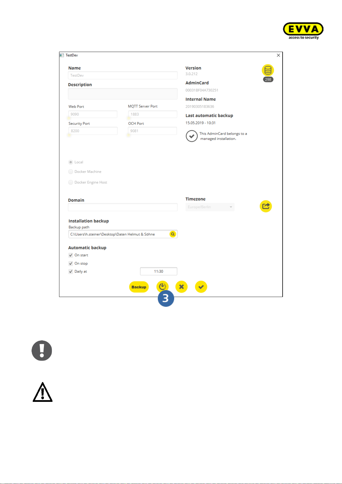
85
KPM.X.Systemhandbuch_X3.0.EN.V1.9 | Subject to misprints and technical changes.
Click on the update download button (3) to start the software update
As of version 3.0.212 updates can also be performed with open maintenance
tasks.
For data security, an automatic backup is performed before an update. If an update
was unsuccessful, then this backup file can be used to perform a new system instal-
lation (restore). (See section 6.4 Restore)
Page 86
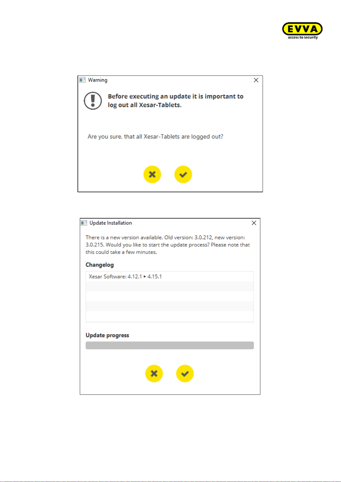
86
KPM.X.Systemhandbuch_X3.0.EN.V1.9 | Subject to misprints and technical changes.
Before a software update, all tablets in the system must be logged out. Confirm that all
tablets are logged out
All version changes are displayed in the software update. Confirm to begin updating.
Page 87
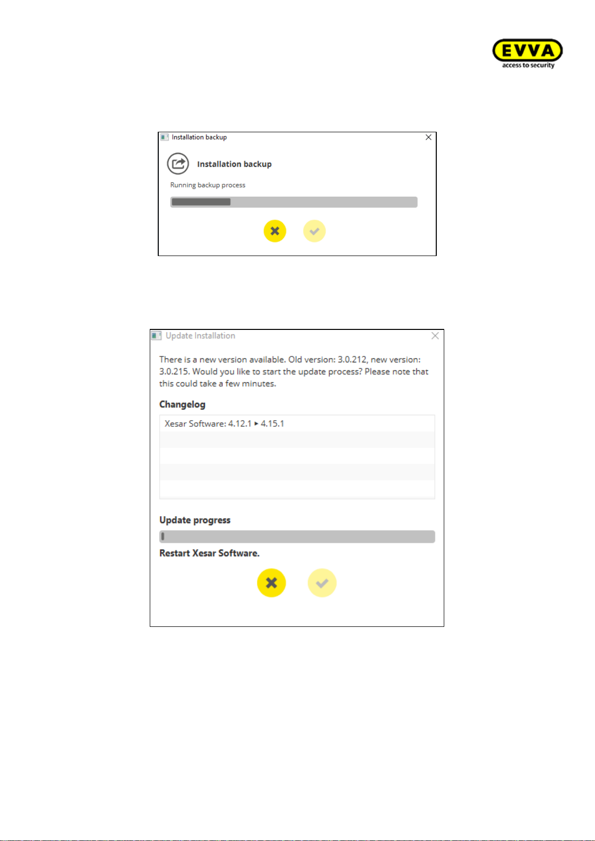
87
KPM.X.Systemhandbuch_X3.0.EN.V1.9 | Subject to misprints and technical changes.
An automatic system data backup is performed before the backup.
Then an update of the individual versions is carried out. Progress is displayed.
Page 88
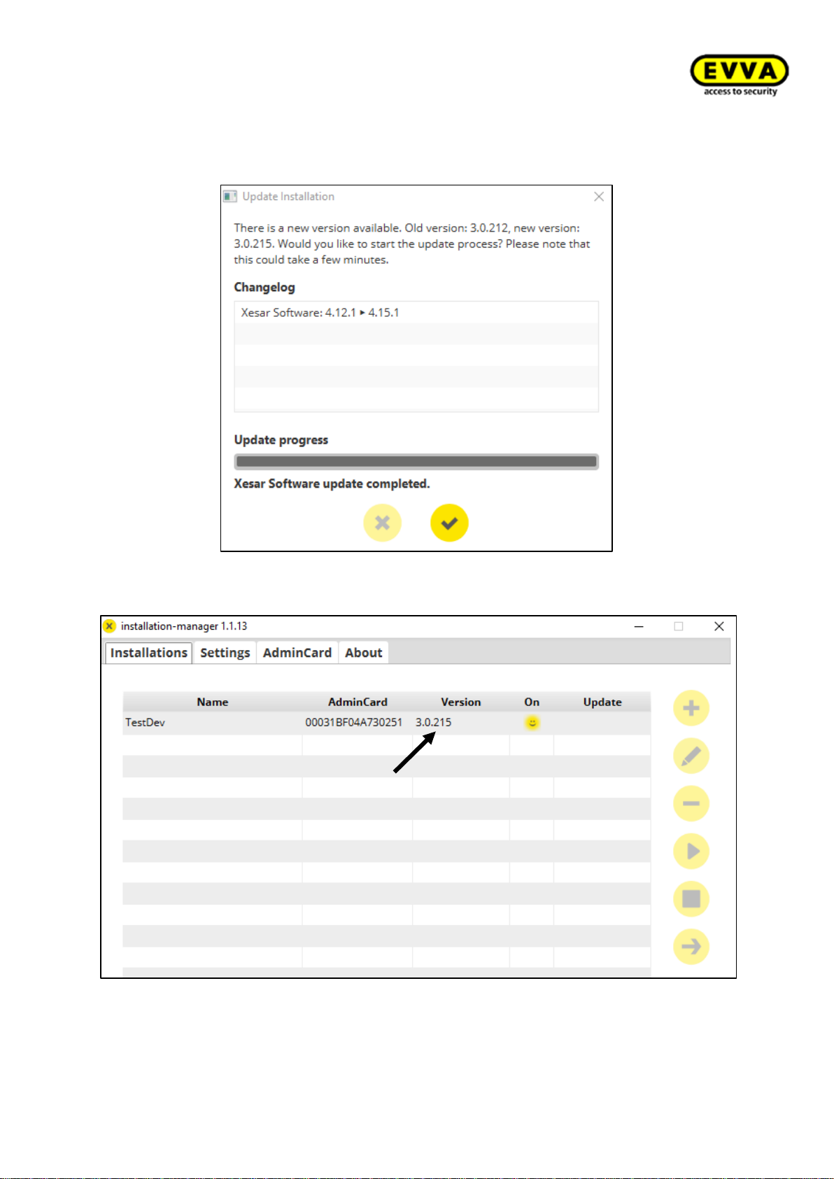
88
KPM.X.Systemhandbuch_X3.0.EN.V1.9 | Subject to misprints and technical changes.
The update is complete.
Confirm to return to the Installation Manager.
The new software version is now added to the version column
Page 89
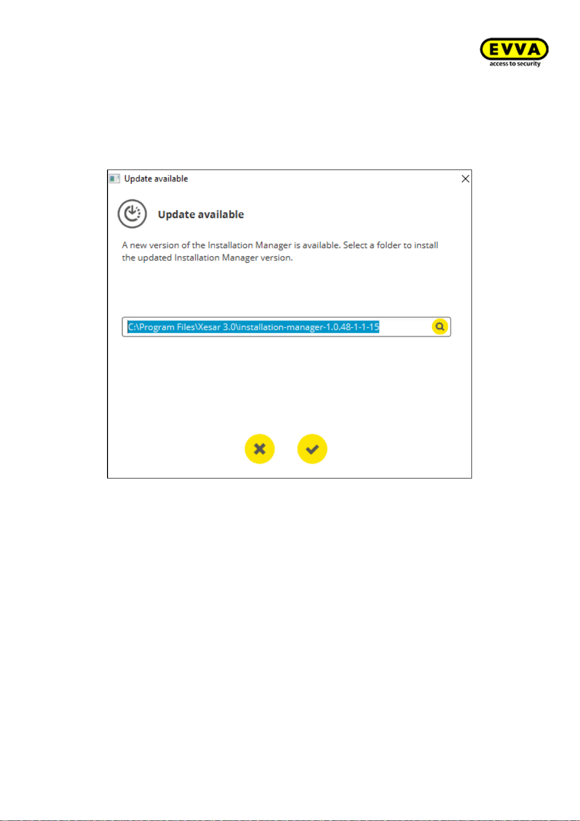
89
KPM.X.Systemhandbuch_X3.0.EN.V1.9 | Subject to misprints and technical changes.
Installation Manager update
If a new version of the Installation Manager is available then the following message appears when starting the Installation Manager:
• Enter the target directory to install the new Installation Manager.
• Unzip the download file and start the new Installation Manager.
• In future only use the latest version of the Installation Manager.
Page 90
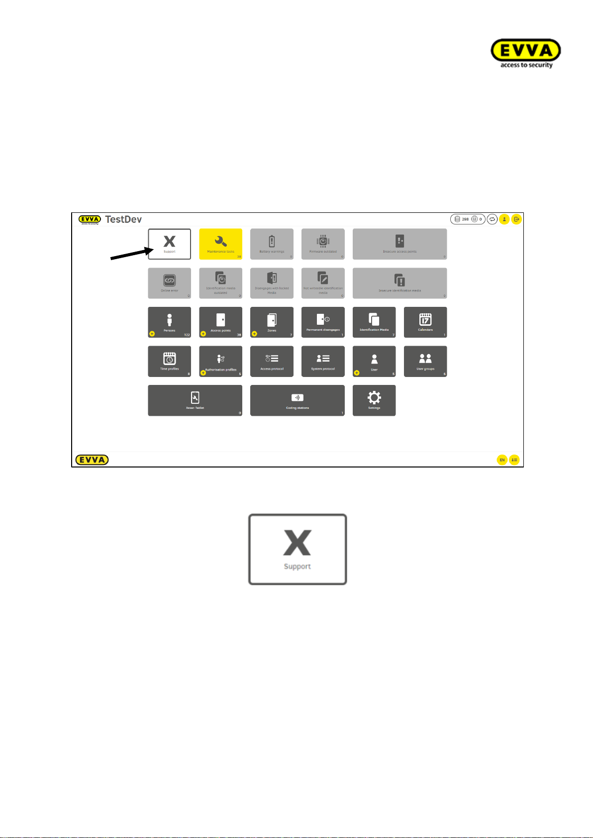
90
KPM.X.Systemhandbuch_X3.0.EN.V1.9 | Subject to misprints and technical changes.
5.4 Periphery Manager:
The Periphery Manager enables the operation of the coding station on the client computer. The coding station is used to create, write to, read and update identification
media.
1. Step: The Periphery Manager is on the Xesar workstation under the Xesar Support
tile.
Figure 74 – Desktop - selecting support
Figure 75 – Support tile
Page 91
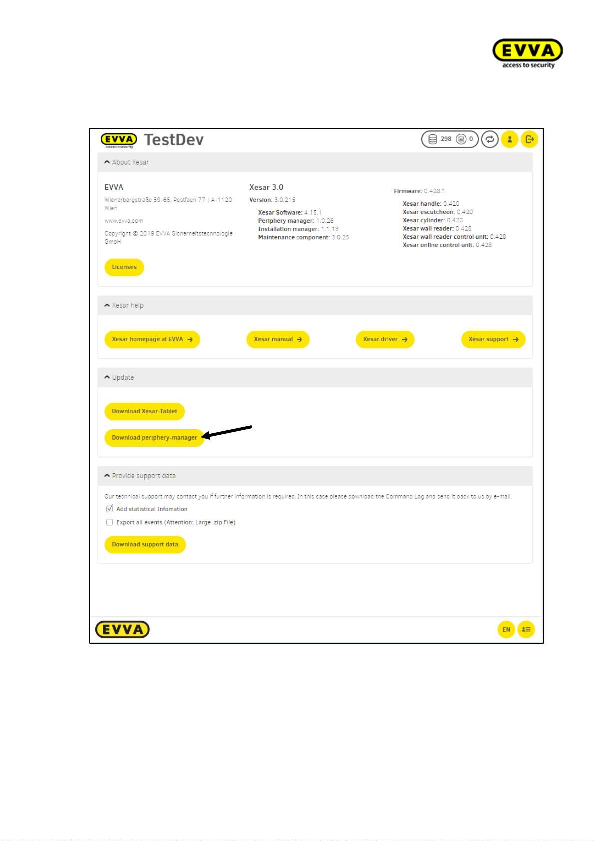
91
KPM.X.Systemhandbuch_X3.0.EN.V1.9 | Subject to misprints and technical changes.
2. Step: Click on „Download Periphery manager“.
Figure 76 - Periphery Manager selection
Page 92
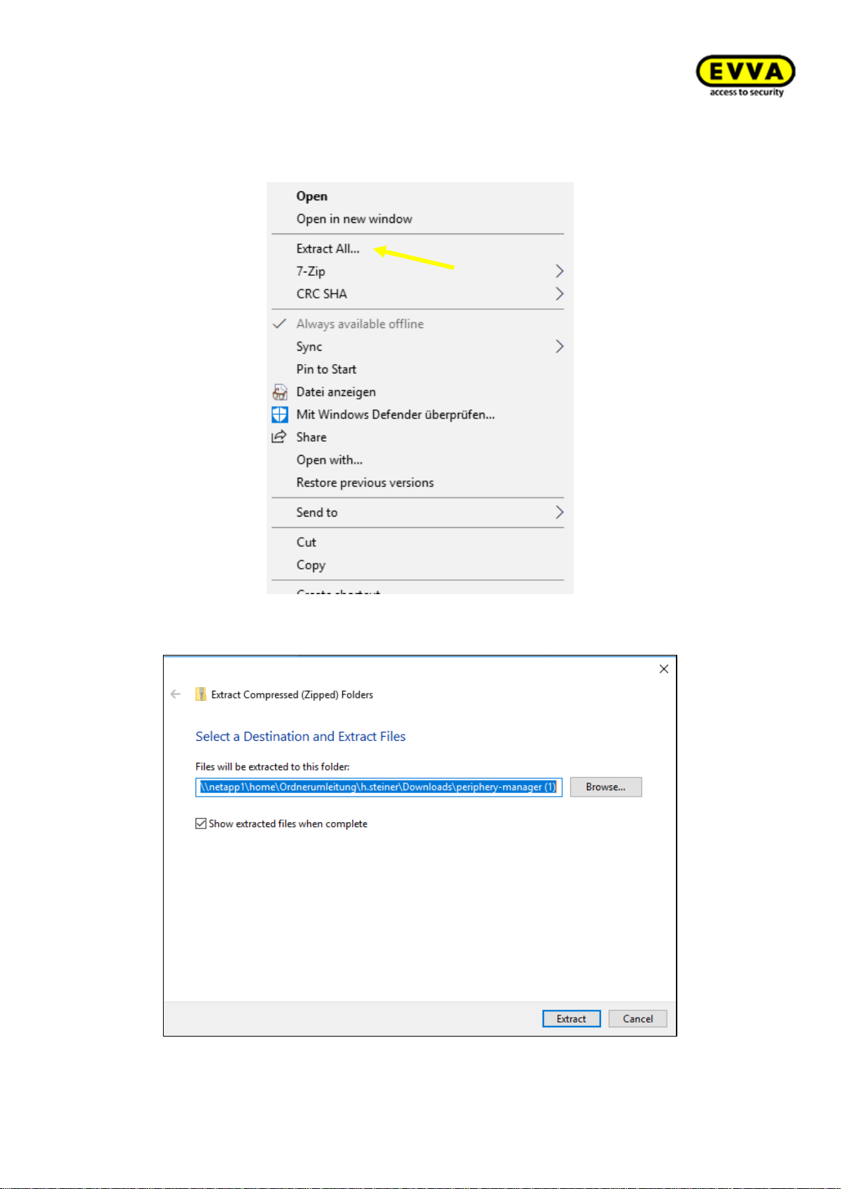
92
KPM.X.Systemhandbuch_X3.0.EN.V1.9 | Subject to misprints and technical changes.
3. Step: unpack the ZIP file.
Figure 77 - Extracting the Periphery Manager ZIP file
Figure 78 - Extracting the Periphery Manager ZIP file
Page 93
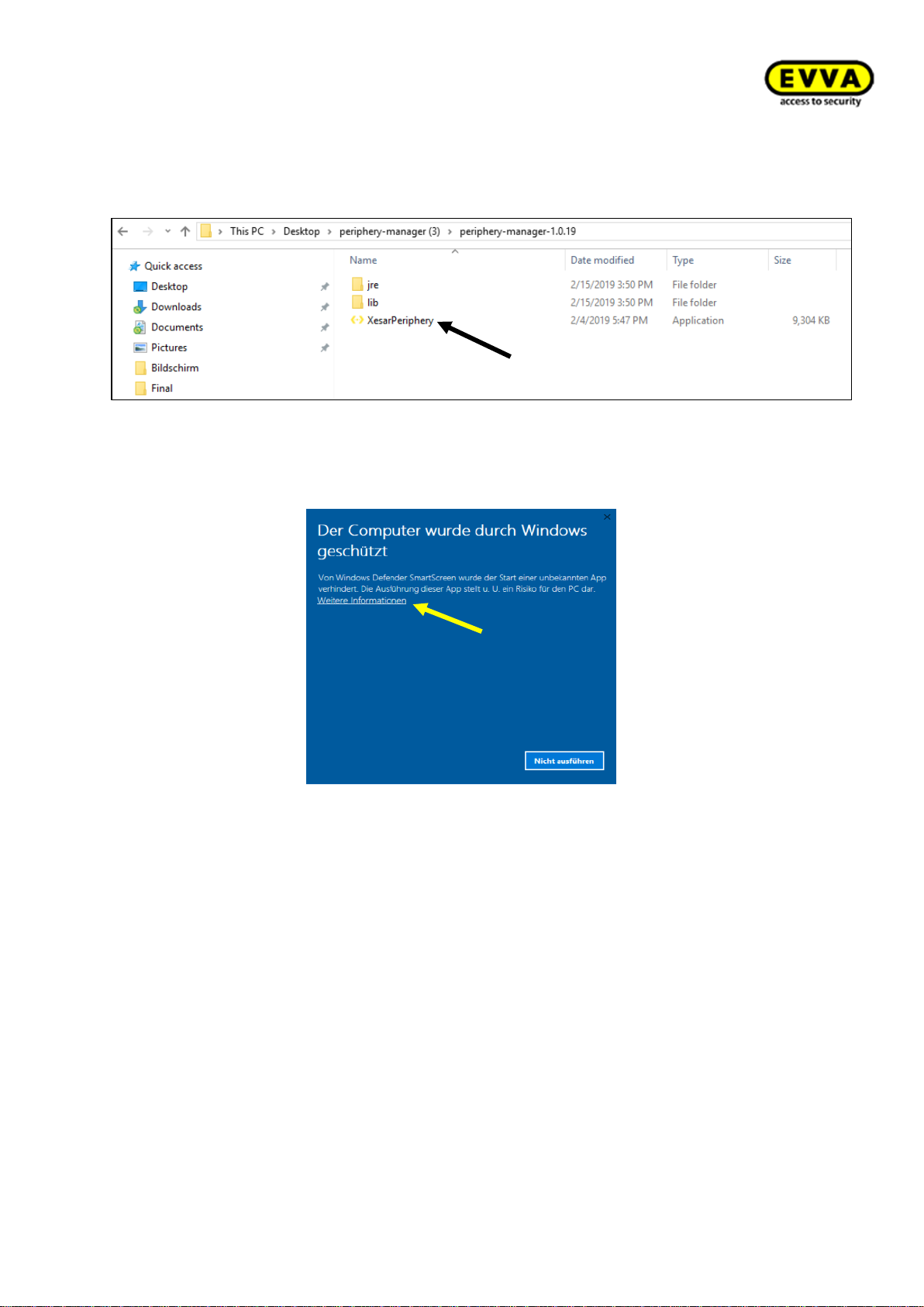
93
KPM.X.Systemhandbuch_X3.0.EN.V1.9 | Subject to misprints and technical changes.
4. Step: Double-click the "Periphery-Manager-x.x.x" folder and open the "Periphery
Manager" application file Double-click the application file.→
Figure 79 – Xesar periphery application
Windows may potentially show warnings: Please click "Additional information".
Figure 80 – Xesar periphery application – warning
Page 94
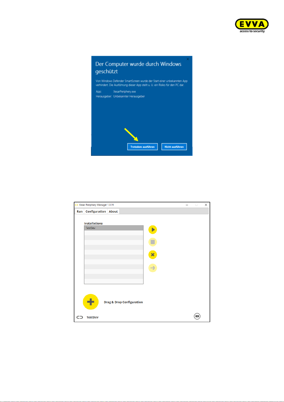
94
KPM.X.Systemhandbuch_X3.0.EN.V1.9 | Subject to misprints and technical changes.
Click "Run anyway".
Figure 81 – Xesar Periphery Manager, warning 2
You may see additional warnings, please accept them and continue.
5. Step: Xesar Periphery Manager opens.
Figure 82 – Periphery Manager
The Periphery Manager is now ready for use!
Page 95
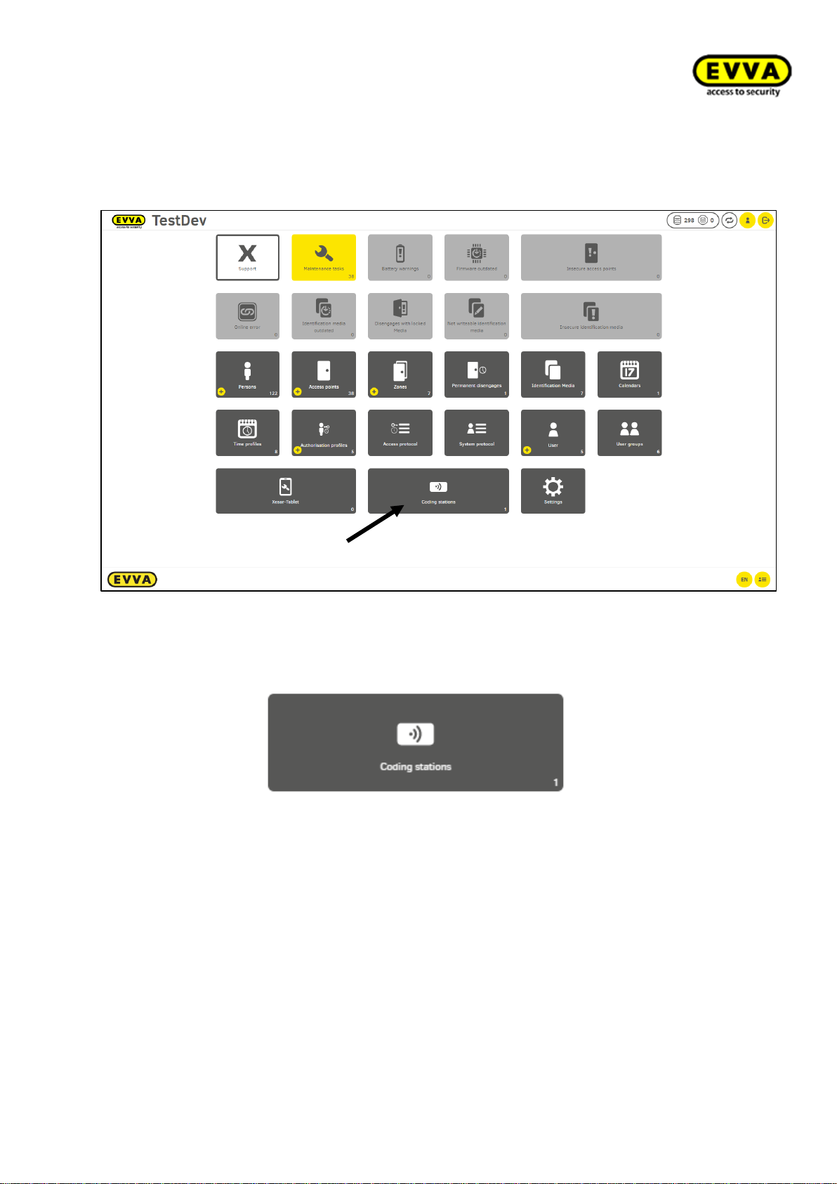
95
KPM.X.Systemhandbuch_X3.0.EN.V1.9 | Subject to misprints and technical changes.
5.5 Linking the coding station to the Xesar software
Proceed as follows to use a connected coding station with the Xesar software:
Figure 83 – Coding station on the dashboard
1. Step: creating the coding station: Click the coding station tile on the Xesar dashboard.
Figure 84 – Coding stations tile
Page 96
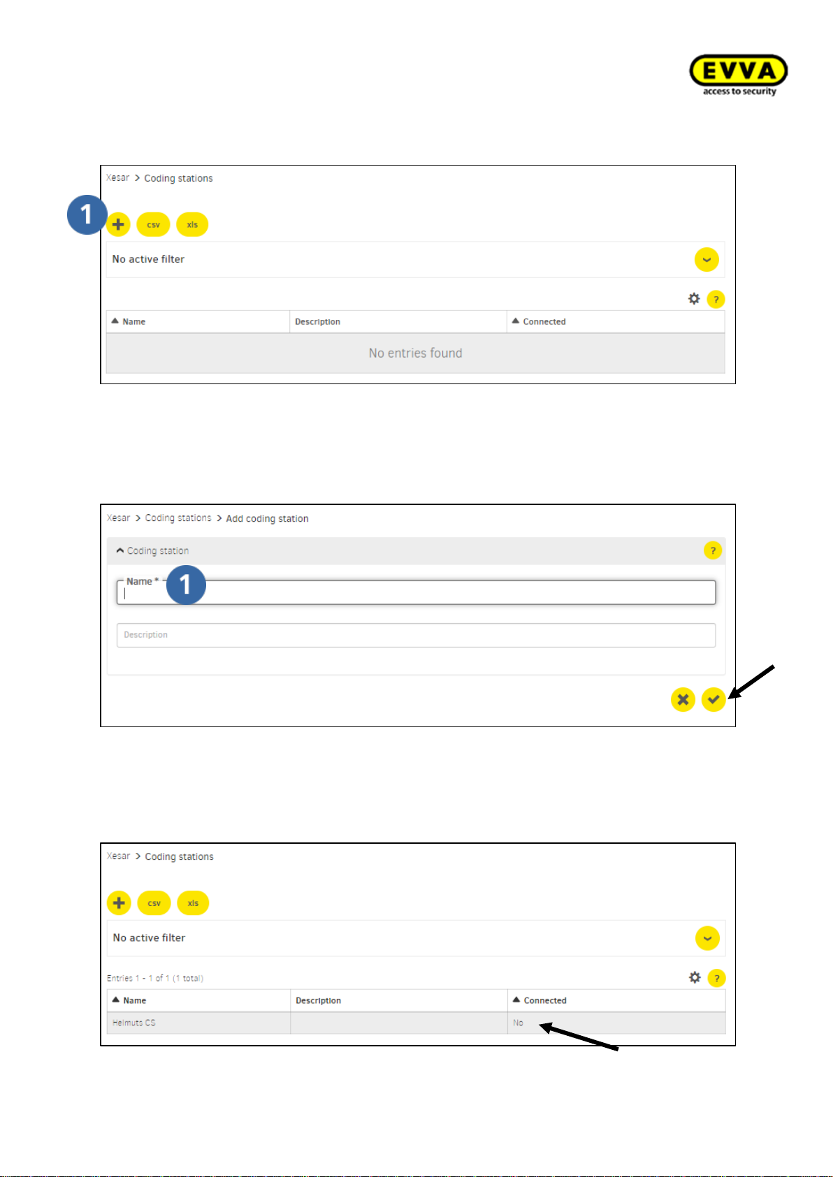
96
KPM.X.Systemhandbuch_X3.0.EN.V1.9 | Subject to misprints and technical changes.
2. Step: Click the "+" icon to add a new coding station.
Figure 85 – Adding a coding station
3. Step: Enter the name and potentially a description and click the "Confirm" icon.
Figure 86 – Coding station, adding names
4. Step: coding station has now been entered in the overview list, but not connected
to the client computer.
Figure 87 – Coding station status
Page 97
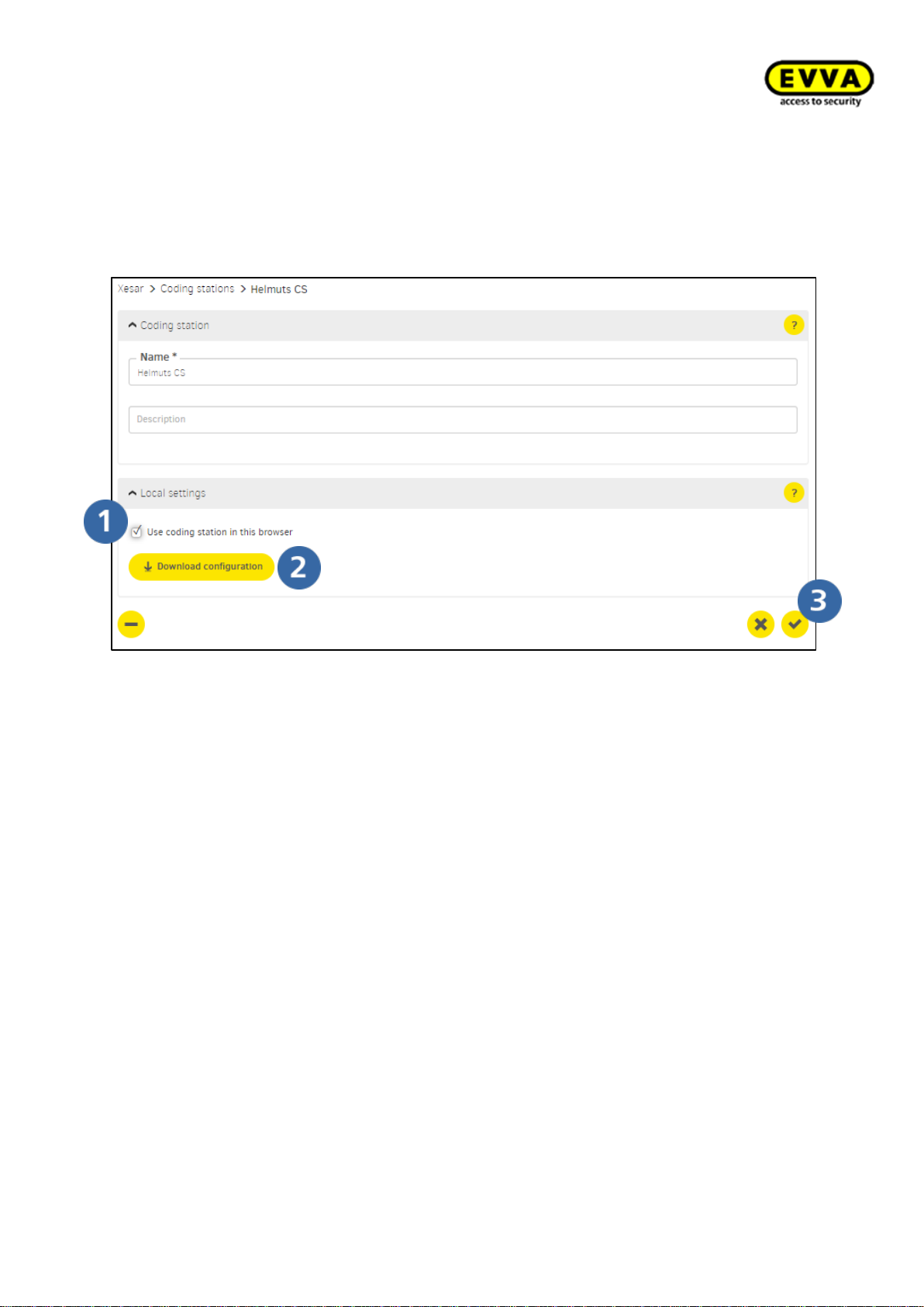
97
KPM.X.Systemhandbuch_X3.0.EN.V1.9 | Subject to misprints and technical changes.
5. Step: Activating the coding station and downloading the configuration file
a. Click the coding station's list entry
b. Select the "Use coding station in this browser" option
c. Click the "Download" icon and download the coding station's configuration file.
d. Click the "Confirm" icon to save your input!
Figure 88 – Download the coding station's configuration file
Page 98
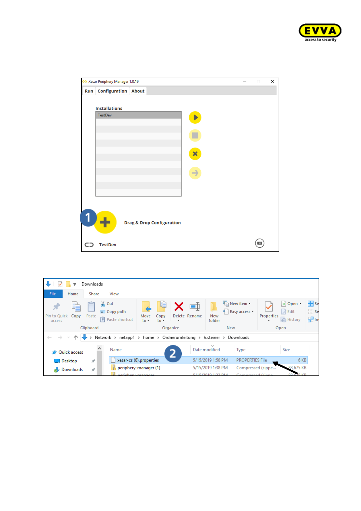
98
KPM.X.Systemhandbuch_X3.0.EN.V1.9 | Subject to misprints and technical changes.
6. Step: In the Periphery Manager click the "+" icon to import the configuration file.
The configuration file name ends with "properties".
Figure 89 - Add Periphery Manager configuration file
Figure 90 - Select Periphery Manager configuration file
Page 99
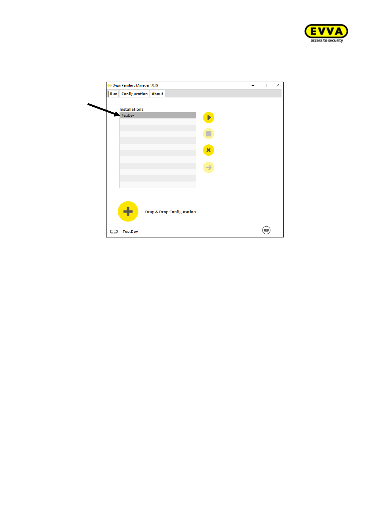
99
KPM.X.Systemhandbuch_X3.0.EN.V1.9 | Subject to misprints and technical changes.
Your installation (name of your system) is now shown as a list entry in the Periphery Manager.
Figure 92 – Xesar system in Periphery Manager
Page 100
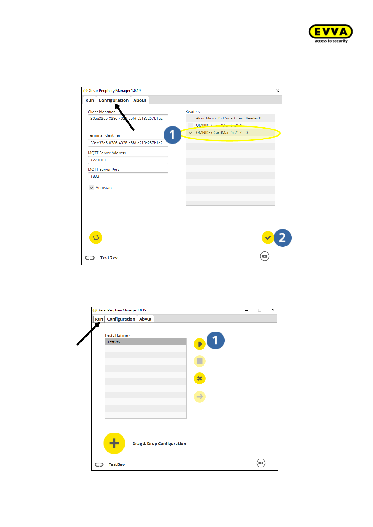
100
KPM.X.Systemhandbuch_X3.0.EN.V1.9 | Subject to misprints and technical changes.
7. Step: select the "Configuration" tab.
a. Select the reader unit designated as OMNIKEY with CL.
b. Click the "Save" icon.
Figure 91 – Periphery Manager, selection of the coding station
8. Step: Select the "Run" tab and click the "Start" icon to start the Periphery Man-
ager.
Figure 92 - Periphery Manager start
 Loading...