

Page 1

EyeCheck 5xxx
Specification
EVT GmbH, Haid-und-Neu-Str. 7, 76131 Karlsruhe, Germany www.evt-web.com, info@evt-web.com
Tel.: 0049 721 668 004 23 0
Page 2

Contents
1. Feature..............................................................................................................................................3
2. Application.......................................................................................................................................4
2.1 Application.................................................................................................................................4
2.2 Application Diagram..................................................................................................................5
3. Specification.....................................................................................................................................5
3.1 Product Model – Camera...........................................................................................................5
3.2 Product Model – I/O Module.....................................................................................................6
3.3 Product Model LED Illuminator................................................................................................7
3.4 Specifications.............................................................................................................................7
3.5 System Block Diagram..............................................................................................................9
4. Interface – Camera.........................................................................................................................10
4.1 Ports on Panel..........................................................................................................................10
4.2 Internal USB 2.0 Port...............................................................................................................11
4.3 LED Drivers.............................................................................................................................11
5. Interface – I/O Module...................................................................................................................11
5.1 Camera Port.............................................................................................................................12
5.2 Power Port................................................................................................................................12
5.2.1 Power Input......................................................................................................................12
5.2.2 Trigger Input....................................................................................................................12
5.2.3 LED Driver output...........................................................................................................13
5.3 General Input Port....................................................................................................................13
5.4 General Output Ports...............................................................................................................14
5.5 RS232 Ports.............................................................................................................................16
5.6 Ethernet Port............................................................................................................................16
5.7 USB2.0 Ports...........................................................................................................................16
5.8 Power Button...........................................................................................................................16
6. Functions Instructions....................................................................................................................16
6.1 Shutter Time.............................................................................................................................17
6.1.1 Minimum Shutter Time....................................................................................................17
6.1.2 Maximum Shutter Time...................................................................................................17
6.2 LED Drivers.............................................................................................................................17
6.3 Trigger Input............................................................................................................................18
6.3.1 Active Trigger Edge.........................................................................................................18
6.3.2 Input Signal Glitch Filter.................................................................................................18
6.3.3 Trigger Delay...................................................................................................................18
6.3.4 Delayed Triggering..........................................................................................................18
6.4 General input............................................................................................................................18
6.4.1 Active Triggering Edge....................................................................................................18
6.4.2 Input Signal Glitch Filter.................................................................................................18
6.4.3 Input Delay.......................................................................................................................18
6.5 General Output.........................................................................................................................19
6.6 Camera Recovery.....................................................................................................................19
7. Dimensions.....................................................................................................................................20
EVT GmbH, Haid-und-Neu-Str. 7, 76131 Karlsruhe, Germany www.evt-web.com, info@evt-web.com
Tel.: 0049 721 668 004 23 0
Page 3

1. Feature
1. Intel ATOM CPU inside (E3845 @ 1.91 GHz, quad-core, 64-bit)
2. 4G-Byte DRAM, 64G-Byte storage, soldered on board
3. 64-bit OS: Windows 10 IoT Enterprise, Linux (Ubuntu)
4. Global Shutter CCD/CMOS, resolution from 0.3 MP to 12 MP
5. HDMI display port
6. 2 programmable constant current LED drivers
7. Free standard accessories: I/O module and connecting cables
8. Rock-solid system stability, operating temperature from -40°C to +80°C
EVT GmbH, Haid-und-Neu-Str. 7, 76131 Karlsruhe, Germany www.evt-web.com, info@evt-web.com
Tel.: 0049 721 668 004 23 0
Page 4

2. Application
2.1 Application
• Surface inspection, High-accuracy measuring
• OCR, Bar code, DMC, QR recognition
• Matching, Classification
2.2 Application Diagram
EVT GmbH, Haid-und-Neu-Str. 7, 76131 Karlsruhe, Germany www.evt-web.com, info@evt-web.com
Tel.: 0049 721 668 004 23 0
Page 5

3. Specification
3.1 Product Model – Camera
Model Type Resolution
Max.
FPS
Shutter Sensor Description
EC5000 Mono 640x480 120 Global
SHARP CCD RJ33B4AA0DT, 1/3", 7.4um
EC5000c Color 640x480 120 Global
SHARP CCD RJ33B3AA0DT, 1/3", 7.4um
EC5010 Mono 640x480 200 Global
SHARP CCD RJ33B4AA0DT, 1/3", 7.4um
EC5010c Color 640x480 200 Global
SHARP CCD RJ33B3AA0DT, 1/3", 7.4um
EC5200 Mono 1280x960 30 Global
SHARP CCD RJ33J4CA0DT, 1/3", 3.75um
EC5200c Color 1280x960 30 Global
SHARP CCD RJ33J3CA0DT, 1/3", 3.75um
EC5300 Mono 1280x1024 105 Global
ONSEMI CMOS NOIP3SN1300A, 1/2", 4.8um
EC5300c Color 1280x1024 105 Global
ONSEMI CMOS NOIP3SE1300A, 1/2", 4.8um
EC5400 Mono 1616x1232 50 Global
SHARP CCD RJ31N4AD0DT, 1/1.8", 4.4um
EC5400c Color 1616x1232 50 Global
SHARP CCD RJ31N3AD0DT, 1/1.8", 4.4um
EC5410c Color 1616x1232 15 Global
SONY CCD ICX274AQ, 1/1.8", 4.4um
EC5500 Mono 2048x1536 55.6 Global
SONY CMOS IMX265LLR, 1/1.8", 3.45um
EC5500c Color 2048x1536 55.6 Global
SONY CMOS IMX265LQR, 1/1.8", 3.45um
EC5600 Mono 2448x2048 15 Global
SHARP CCD RJ32S4AD0DT, 2/3", 3.45um
EC5600c Color 2448x2048 15 Global
SHARP CCD RJ32S3AD0DT, 2/3", 3.45um
EC5610 Mono 2456x2048 35.7 Global
SONY CMOS IMX264LLR, 2/3", 3.45um
EC5610c Color 2456x2048 35.7 Global
SONY CMOS IMX264LQR, 2/3", 3.45um
EC5700 Mono 3072x2048 30 Rolling
SONY CMOS IMX178LLJ, 1/1.8", 2.4um
EC5700c Color 3072x2048 30 Rolling
SONY CMOS IMX178LQJ, 1/1.8", 2.4um
EC5900c Color 4000x3000 20 Rolling
SONY CMOS IMX226CQJ, 1/1.7", 1.85um
EVT GmbH, Haid-und-Neu-Str. 7, 76131 Karlsruhe, Germany www.evt-web.com, info@evt-web.com
Tel.: 0049 721 668 004 23 0
Page 6

3.2 Product Model – I/O Module
Model EC-M100A
Description
EyeCheck 5xxx Series Industrial Smart Camera I/O Module
3.3 Product Model LED Illuminator
Model Color Wave Length or Color
Temperature
Beam Angle Max. Driving
Current
EC-LW45 White 6500K 45° 300mA
EC-LW90 White 6500K 90° 300mA
EC-LR60 Red 624nm 60° 100mA
EC-LY60 Yellow 590nm 60° 100mA
EC-LG60 Green 525nm 60° 100mA
EC-LB60 Blue 470nm 60° 100mA
EC-LI60 IR 850nm 60° 100mA
EVT GmbH, Haid-und-Neu-Str. 7, 76131 Karlsruhe, Germany www.evt-web.com, info@evt-web.com
Tel.: 0049 721 668 004 23 0
Page 7

3.4 Specifications
CPU Model Intel ATOM CPU E3845
CPU Type Quad-core 1.91GHz, 64-bit x86
L2 Cache 2M-byte
GPU Support DirectX11, OpenGL3.0, OpenCL1.2
Memory 4G-byte DDR3L-1333 (solder on board)
Storage 64G-byte eMMC5.0 Flash (solder on board)
Ethernet One Gigabit Ethernet by Intel I210 controller
USB Three USB 2.0 ports
One internal USB 2.0 (inside camera casing, dedicated for USB dongle)
Monitor Port One HDMI port, support resolution from VGA (640x480) to 1080P
Serial Port Two 9-pin RS232 ports with TX/RX signal only
Trigger Input One isolated trigger input (5V/12V/24VDC supported)
General Input Eight photo-isolated input ports (5V/12V/24VDC supported)
General Output Eight photo-isolated output ports (Max current 0.3A, Max voltage 40VDC)
LED Driver Two constant current LED drivers, output current adjustable:
Internal LED driver only supports EVT LED board, with max output 0.3A/24V
External LED driver (in IO module) supports general LED illuminator, with
max output 1.5A/24V
LED Indicator Five red/green indicators: Power, LAN and three user-defined LEDs
Delayed
Triggering
Delayed triggering is supported:
Up to 32 delayed instances, each instance can be delayed up to 60 seconds,
time precision: 1 microsecond
Watchdog Hardware Watchdog timer (1 to 256 second adjustable)
Encryption Unique chip ID encryption; dedicated encryption chip LKT4300 (soldered on
board)
Temperature
Monitoring
Internal temperature sensor, real-time mainboard temperature monitoring
Remote Control WoL (Wake on LAN) supported, remote control via Ethernet
OS (64bit) Windows 10 IoT Enterprise, Linux (Ubuntu)
Power Consumption 12W Max
Power Supply 20 to 30 VDC (24 VDC recommended), 2A Max
Operation Condition -40°C to +80°C
Storage Condition -40°C to +90°C
Hardware Structure Aluminium alloy casing, fanless design
Dimensions 110 x 61 x 47 mm
Weight 380 g
Standards CE
EVT GmbH, Haid-und-Neu-Str. 7, 76131 Karlsruhe, Germany www.evt-web.com, info@evt-web.com
Tel.: 0049 721 668 004 23 0
C
P
U
I
/
O
M
o
d
u
l
e
S
p
e
c
i
a
l
F
u
n
c
t
i
o
n
s
Page 8

Note:
[1] The power consumption of the camera is 12W max. However, it takes more power
consumption when using I/O module for external LED driving. So switching power with
over 80W is recommended.
[2] After being placed in the environment of -40°C for 12 hours, the camera can be
started and run for 24 hours. The camera can run for 48 hours in the environment of
+80°C. The camera can run for 48 hours in the cyclic environment (5 hours for a cycle) of
the temperature form -40°C to +80°C.
[3] The RTC runs for 4 weeks by the internal recharged battery, so time value must be set
again when the camera power supply is cut off more than 4 weeks.
3.5 System Block Diagram
The block diagram of EyeCheck 5xxx series is as follows:
EVT GmbH, Haid-und-Neu-Str. 7, 76131 Karlsruhe, Germany www.evt-web.com, info@evt-web.com
Tel.: 0049 721 668 004 23 0
Page 9

4. Interface – Camera
4.1 Ports on Panel
The EC 5xxx series includes camera and I/O module. They are connected with a HDMI
cable (5 meters, with M3 setscrew). This customized cable is soft, with flexural endurance
and oil resistivity for robot arm and cable chain.
The camera supports standard HDMI display port for displaying on monitor with HDMI
port, supporting resolution from VGA (640x480) to 1080P.
Notice: the 3-meter HDMI cable with M3 setscrew may not match all monitors because of
the connector size. Some monitors are ensured to match the cable.
The ports for I/O module and HDMI monitor look the same. However EVT provides faulttolerant design which allows misplug without any damage to the camera.
4.2 Internal USB 2.0 Port
This USB 2.0 port is hidden inside the camera casing. User can use this port only when
opening the rear panel.
This internal USB port is designed for encryption USB dongle to avoid misplug.
4.3 LED Drivers
EVT provides constant current LED drivers on both, camera and I/O module with
adjustable current (LED brightness) for machine vision applications, which reduces system
costs and increases system stability.
The internal LED driver has max output 300mA/24V for EVT-designed illuminator only.
EVT GmbH, Haid-und-Neu-Str. 7, 76131 Karlsruhe, Germany www.evt-web.com, info@evt-web.com
Tel.: 0049 721 668 004 23 0
Page 10

5. Interface – I/O Module
5.1 Camera Port
The port marked with “Camera” is for connection with the camera. With a customized
cable, the camera can be connected with I/O module for ports extension. The cable is 5
meter long with M3 setscrews. Also available 8 meter cable on request.
5.2 Power Port
The 8-pin port marked “POWER” is the power port. This connector is compatible with
16-24 AWG wire. The 8-pin power port includes power input, trigger input, LED driver
output and casing Earth.
5.2.1 Power Input
The power input ports marked with “0V” and “24VDC”, support 20 to 30VDC (24VDC is
recommended) input. This port supports reverse polarity protection, undervoltage
protection, overvoltage protection and surge protection.
The power consumption of the camera is 12W max. However, it takes more power
consumption when using I/O module for external LED driving. So power supply with over
24V/24 is recommended.
EVT GmbH, Haid-und-Neu-Str. 7, 76131 Karlsruhe, Germany www.evt-web.com, info@evt-web.com
Tel.: 0049 721 668 004 23 0
Page 11

5.2.2 Trigger Input
The trigger input port marked with “TRIG+” and “TRIG-”, is for external triggering signal
like position sensor on production line.
Trigger input is a photo-isolated input, it can input 5V/12V/24VDC signal directly with no
need for an external current-limiting resistor. -30V to +1V is recognized as low level, and
+2.8 to +30V is recognized as high level, with input current below 2mA; voltage out of
range from -30V to +30V may damage the circuit.
5.2.3 LED Driver output
The ports marked with “LED+” and “LED-” are for driving general passive LED illuminator.
Please connect LED anode with “LED+” and connect cathode with “LED-”.
The max. output voltage is 24V (so it supports LED illuminator under 24VDC), and the
max. output current is 1.5A (1500mA). User can rapidly adjust the current (or brightness
of LED) from 0mA to 1500mA by software.
EVT GmbH, Haid-und-Neu-Str. 7, 76131 Karlsruhe, Germany www.evt-web.com, info@evt-web.com
Tel.: 0049 721 668 004 23 0
Page 12

5.3 General Input Port
The general input port is a 9-pin port marked with “INPUT”. It is compatible with 1624AWG wire.
There are 8 photo-isolated general input ports, they can input 5V/12V/24VDC signal
directly with no need for an external current-limiting resistor. -30V to +1V is recognized as
low level, and +2.8 to +30V is recognized as high level, with input current below 2mA;
voltage out of range from -30V to +30V may damage the circuit.
It is recommended to use PNP output type sensors, switches or PLC.
EVT GmbH, Haid-und-Neu-Str. 7, 76131 Karlsruhe, Germany www.evt-web.com, info@evt-web.com
Tel.: 0049 721 668 004 23 0
Page 13
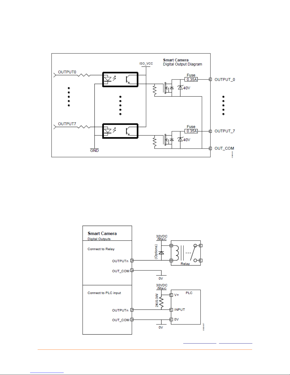
5.4 General Output Ports
The general output port is a 10-pin port marked with “OUTPUT”. It is compatible with 1624AWG wire.
There are 8 photo-isolated general output ports (NPN type) for driving resistive load or
inductive load. The ports can sink 350mA/30V current. These ports need no fly-wheel
diode when driving inductive load, because there are zener diodes onboard. The output
saturation voltage Von is less than 0.2V @ 350mA, and leakage corrent Ioff-leek is less than
50uA.
As the concept of relay (definitions of OPEN and CLOSE), the MOSFET does not conduct
when API sent command OPEN; when command CLOSE is sent, the MOSFET conducts and
sinks up to 350mA current. The camera default setting is no output (OPEN) when power
on.
EVT GmbH, Haid-und-Neu-Str. 7, 76131 Karlsruhe, Germany www.evt-web.com, info@evt-web.com
Tel.: 0049 721 668 004 23 0
Page 14

This output delay time may be variable because of OS thread scheduling and user
programming style, usually range from 0.1ms to 1ms.
5.5 RS232 Ports
There are two RS232 ports (standard DB9 connector) with mark “RS232-1” and “RS2322”. The two RS232 ports have only RX/TX signals for external devices like PLC, with
supporting baud rate (bps): 230400, 153600, 115200, 57600, 19200, 9600, 4800, 2400,
600, 300.
5.6 Ethernet Port
There is a Gigabit Ethernet marked with “GigaEthernet”. This port is used to connect with
PC or PLC. Also, it can connect with other GigE cameras. PoE (Power over Ethernet)
function is not supported.
If working in Gigabit mode, CAT-6 or CAT-6E cable is recommended for a better
performance. The default IP address is 192.168.1.218.
5.7 USB2.0 Ports
There are three USB2.0 ports marked with “USB1”, “USB2”, “USB3”. These USB ports are
for connecting keyboard, mouse, USB flash drive and other general USB external devices.
The output power of each port is 5V/0.5A.
5.8 Power Button
There is a self-lock push button marked with “POWER”. The OS is highly customized to
avoid accident from power failure, which means all cameras are able to work on
production line with frequent power off without shutting down OS from desktop.
EVT GmbH, Haid-und-Neu-Str. 7, 76131 Karlsruhe, Germany www.evt-web.com, info@evt-web.com
Tel.: 0049 721 668 004 23 0
Page 15

6. Functions Instructions
Below are some instructions of camera special functions for machine vision.
6.1 Shutter Time
6.1.1 Minimum Shutter Time
Like other industrial cameras, the EyeCheck 5xxx has minimum shutter time limit.
Because the features of different CCD/CMOS sensors are different, this minimum value for
different models is different. If using illegal parameters (lower than the minimum value) to
set shutter time by API, the camera will set the only according to the minimum value.
Model Minimum Value (us) Note
EC5000 & EC5000c
EC5010 & EC5010c
8
EC5300 & EC5300c 10
EC5200 & EC5200c 17
EC5400 & EC5400c 11
EC5500 & EC5500c 14
EC5610 & EC5610c 14
EC5600 & EC5600c 20
EC5700 & EC5700c 3
EC5900 3
The shutter time is adjustable by microseconds.
6.1.2 Maximum Shutter Time
The maximum shutter time is 1 second, and it is adjustable by microseconds.
6.2 LED Drivers
Constant current LED drivers on both camera and I/O module are available with adjustable
current for machine vision applications.
This function can greatly increase the life cycle of LED and reduce the system power
consumption.
EVT GmbH, Haid-und-Neu-Str. 7, 76131 Karlsruhe, Germany www.evt-web.com, info@evt-web.com
Tel.: 0049 721 668 004 23 0
Page 16

6.3 Trigger Input
6.3.1 Active Trigger Edge
The trigger input port accepts rising edge signal or falling edge signal. The default setting
is rising edge signal.
6.3.2 Input Signal Glitch Filter
The input signal glitch filter function is disabled by default.
If this function is enabled, when the first trigger signal edge is received, system will
double checks after the glitch filter delay time. Only when two results (before and after
glitch filter delay time) are the same can the input trigger be accepted. For general digital
sensors, this function is not recommended. However, for input trigger from mechanical
switch, this function is very useful to avoid spurious triggering.
6.3.3 Trigger Delay
The time period between trigger signal input and image exposure starting is called
triggering delay.
6.3.4 Delayed Triggering
For some machine vision applications, the triggering sensor is far from the camera,
between which there are several components moving on production lines. In this case,
delayed triggering function is necessary. EyeCheck 5xxx camera supports up to 32 delayed
instances, each instance can be delayed up to 60 seconds, time precision: 1 microsecond.
6.4 General input
6.4.1 Active Triggering Edge
The trigger input port accepts rising edge signal or falling edge signal. The default active
edge is rising edge. It is recommended to use PNP output type sensors, switches or PLC,
because they can direct interface with the trigger port.
6.4.2 Input Signal Glitch Filter
The input signal glitch filter function is disabled by default. If this function is enabled,
when the first trigger signal edge is received, system will double checks after the glitch
filter delay time. Only when two results (before and after glitch filter delay time) are the
same can the input signal be accepted. For general digital sensors, this function is not
recommended. However, for input trigger from mechanical switch, this function is very
useful to avoid malfunction. The glitch filter delay time should be set according to the field
tests.
6.4.3 Input Delay
The time period between general input and user’s program receiving message is called
input delay. This input delay time may be variable because of OS thread scheduling and
user programming style, usually range from 0.1ms to 1ms.
EVT GmbH, Haid-und-Neu-Str. 7, 76131 Karlsruhe, Germany www.evt-web.com, info@evt-web.com
Tel.: 0049 721 668 004 23 0
Page 17

6.5 General Output
As the concept of relay (definitions of OPEN and CLOSE), the MOSFET does not conduct
when API sent command OPEN; when command CLOSE is sent, the MOSFET conducts and
sinks up to 350mA current. The camera default setting is no output (OPEN) when power
on. This output delay time may be variable because of OS thread scheduling and user
programming style, usually range from 0.1ms to 1ms.
6.6 Camera Recovery
The EyeCheck 5xxx supports recovery function, including BIOS and OS recovery. User can
easily recover the camera to factory default status.
EVT GmbH, Haid-und-Neu-Str. 7, 76131 Karlsruhe, Germany www.evt-web.com, info@evt-web.com
Tel.: 0049 721 668 004 23 0
Page 18

7. Dimensions
EVT GmbH, Haid-und-Neu-Str. 7, 76131 Karlsruhe, Germany www.evt-web.com, info@evt-web.com
Tel.: 0049 721 668 004 23 0
 Loading...