

EVSE 3725-104 User Manual And Installation Manual
Control Module Inc., EVSE LLC
User Manual and Installation Guide
Models 3725-104
EVSE Payment Module
Patents Pending
3725-UG-002
February 2018
State of the Art EVSE with Cable Management
EVSE Payment Module
Model 3725-104
Contents
Important Notes .............................................................................................................................................................................2
Safety and Compliance ...............................................................................................................................................................2
Limitation of Liability ..................................................................................................................................................................3

Page 1
FCC Compliance Statement ........................................................................................................................................................3
Important ....................................................................................................................................................................................3
No Accuracy Guarantee ..............................................................................................................................................................3
Copyright and Trademarks .........................................................................................................................................................3
Instructions Pertaining To Risk Of Fire Or Electrical Shock .............................................................................................................3
Important Safety Instructions .........................................................................................................................................................4
Instructions De Sécurité Importantes .............................................................................................................................................5
Introduction ....................................................................................................................................................................................6
Specifications ..............................................................................................................................................................................8
LOCKOUT/TAGOUT .................................................................................................................................................................. 10
Installation Overview ................................................................................................................................................................... 11
Payment Module Operation ........................................................................................................................................................ 12
Keypad Overlay ........................................................................................................................................................................ 12
Changing the IP Address For Ethernet Connections ................................................................................................................ 12
Charging Display Screens ......................................................................................................................................................... 14
Accessing the Web Browser Interface ......................................................................................................................................... 17
Ethernet Connection .................................................................................................................................................................... 17
Cellular Connection ...................................................................................................................................................................... 17
Logging In ...................................................................................................................................................................................... 17
Changing the IP Address for an Ethernet Connection .................................................................................................................. 18
Setting Up a ZigBee Mesh Network ............................................................................................................................................. 19
Adding an EVSE Via the Web Browser Interface .......................................................................................................................... 20
Testing the ZigBee Mesh Network .......................................................................................................................................... 21
Testing the ZigBee Mesh Network Via the Web Interface ...................................................................................................... 21
Replacing a ZigBee Mesh Payment Module ............................................................................................................................ 22
Via the Payment Module .............................................................................................................................................................. 22
Via the Web Browser Interface .................................................................................................................................................... 22
Web Browser Interface Operation .............................................................................................................................................. 24
Changing EVSE Assigned Numbers (Serial Connection)........................................................................................................... 24
Viewing EVSE Status and Messages ......................................................................................................................................... 24
Viewing Payment Module Information ................................................................................................................................... 25
Resetting a Payment Module .................................................................................................................................................. 25
Status Reporting ...................................................................................................................................................................... 26
Current Status ............................................................................................................................................................................... 26
Historical Events ........................................................................................................................................................................... 26
Charge History .............................................................................................................................................................................. 26
3725-104 User Manual May 20, 2019

Page 2
App Versions ................................................................................................................................................................................. 27
Kiosk Purchase History ................................................................................................................................................................. 27
Connecting to a Network Management System ..................................................................................................................... 28
White List ................................................................................................................................................................................. 29
Adding RFID Cards with Printed Numbers .................................................................................................................................... 29
Adding RFID Cards with No Printed Numbers .............................................................................................................................. 29
Configuring the White List ............................................................................................................................................................ 30
Vehicle List ............................................................................................................................................................................... 31
System Configuration .............................................................................................................................................................. 31
Network Time Protocol (NTP) Settings ......................................................................................................................................... 32
Network Settings .......................................................................................................................................................................... 32
Importing/Exporting Configuration Settings ................................................................................................................................ 33
Kiosk Configuration.................................................................................................................................................................. 35
Payment Considerations ............................................................................................................................................................... 36
Charge Type .................................................................................................................................................................................. 36
Pricing Options ............................................................................................................................................................................. 37
Pricing Schedule............................................................................................................................................................................ 37
Languages ..................................................................................................................................................................................... 37
Common Prompts ......................................................................................................................................................................... 38
All Prompts ................................................................................................................................................................................... 38
Setting Up Credit Cards ........................................................................................................................................................... 39
Credit Card Setup.......................................................................................................................................................................... 39
External Credit Card Setup ........................................................................................................................................................... 40
MDB Setup .................................................................................................................................................................................... 40
Moving, Transporting And Storage: ............................................................................................................................................. 41
Customer Support ........................................................................................................................................................................ 41
Warranty ...................................................................................................................................................................................... 42
Important Notes
Safety and Compliance
This document provides instructions to install and use the Payment Module 3725-104 which manages payment, access and
data communication within a network of Watt Point Charging Stations (EVSEs). Before installation of the Payment Module by
3725-104 User Manual May 20, 2019

Page 3
licensed professionals, you should review this manual carefully and consult with a licensed contractor, licensed electrician
and trained installation expert to ensure compliance with local building practices, climate conditions, safety standards, and
state and local codes. As part of a total EVSE network, the Payment Module and Charging Station should be inspected by a
qualified installer prior to the initial use. Under no circumstances will compliance with the information in this manual relieve
the user of responsibility to comply with all applicable codes or safety standards. This document describes the most
commonly-used installation and mounting scenarios. If situations arise in which it is not possible to perform an installation
following the procedures provided in this document, contact Control Module Inc, EVSE LLC. Control Module Inc, EVSE LLC, is
not responsible for any damages that may occur resulting from custom installations that are not described in this document.
Limitation of Liability
In no event shall Control Module Inc, EVSE LLC, or its authorized distributors be liable for any indirect, incidental, special,
punitive, or consequential damages, including without limitation, lost profits, lost data, loss of use, cost of cover, or loss or
damage to the watt point charging station or Payment Module, arising out of or relating to the use or inability to use this
manual, even if Control Module Inc, EVSE LLC, or its authorized distributors have been advised of the possibility of such
damages.
FCC Compliance Statement
Note: This equipment has been tested and found to comply with the limits for a Class A digital device, pursuant to part 15 of
the FCC Rules. These limits are designed to provide reasonable protection against harmful interference when the equipment
is operated in a commercial environment. This equipment generates, uses and can radiate radio frequency energy and, if not
installed and used in accordance with the instructions, may cause harmful interference to radio communications. Operation
of this equipment in a residential area is likely to cause harmful interference in which case the user will be required to correct
the interference at his own expense.
Important
Changes or modifications to this product not authorized by Control Module Inc, EVSE LLC, could affect the EMC compliance
and revoke your authority to operate this product.
No Accuracy Guarantee
Reasonable effort was made to ensure that the specifications and other information contained in this manual are accurate
and complete at the time of publication. The specifications and other information in this manual, however, are subject to
change at any time and without prior notice.
Copyright and Trademarks
Copyright 2018 Control Module Inc., EVSE LLC. All rights reserved. This material is protected by the copyright laws of the
United States and other countries. It may not be modified, reproduced or distributed without the prior, express written
consent of Control Module Inc., EVSE LLC.
All other products or services mentioned have the trademarks, service marks, registered trademarks or registered service
marks of their respective owners. Control Module Inc., EVSE LLC, has filed several patent applications.
Instructions Pertaining To Risk Of Fire Or Electrical Shock
The following is a summary of safety concerns relevant to the installation and use of the Model 3725-104 Payment Module.
Failure to follow these safety instructions may lead to serious injury, death and/or damage to the equipment.
3725-104 User Manual May 20, 2019

Page 4
WARNING: is used to provide a warning of hazardous voltage and possibility of electric shock.
CAUTION: is used to provide awareness of important safety information in these instructions.
Important Safety Instructions
WARNING: Only qualified personnel should perform the installation. This installation must be performed in
accordance with all local electrical/building codes and ordinances. Follow lockout/tagout
procedures.
Improper connection of the equipment grounding conductor may result in a risk of electric shock.
Reference National Electrical Code, ANSI/NFPA 70 for proper sizing of the ground conductor.
CAUTION: To satisfy FCC RF exposure requirements for mobile transmitting devices, a separation
Additional considerations which will contribute to safe operation of this unit include the following:
DO: - Read all instructions before using this product.
- The device should be supervised when used around children.
- In case of a problem, contact your installer or CMI Customer Support.
DON’T: - Use this product if the enclosure is broken, cracked, open or shows any other indication of
- Attempt to repair or service the unit yourself.
distance of 20 cm or more should be maintained between the antenna(s) of this device
and persons during device operation. To ensure compliance, operations at closer than
this distance is not recommended. The antenna(s) used for this transmitter must not be
co-located in conjunction with any other antenna or transmitter.
damage.
SAVE THESE INSTRUCTIONS
3725-104 User Manual May 20, 2019
Page 5
Instructions De Sécurité Importantes
AVERTISSEMENT: est utilisé pour fournir un avertissement de tension dangereuse et possibilité de choc
électrique.
ATTENTION: est utilisé pour fournir la prise de conscience de l'information de sécurité importante dans ces
instructions.
INSTRUCTIONS DE SÉCURITÉ IMPORTANTES
AVERTISSEMENT: Seul le personnel qualifié devrait effectuer l'installation. Cette installation doit être effectuée
en conformité avec tous les codes électriques/bâtiment locaux et ordonnances. Suivre les
procédures de verrouillage/verrouillage.
Mauvaise connexion de l'équipement de mise à la terre chef d'orchestre peut entraîner un risque
de choc électrique. Référence National Electrical Code, ANSI/NFPA 70 pour le bon
dimensionnement du conducteur au sol.
Ne pas utiliser ce produit si le code de puissance souple ou le câble EV sont effiloché, a rompu
l'isolation ou tout signe de dommage.
ATTENTION: Pour satisfaire les exigences d'exposition RF de la FCC pour les appareils mobiles de transmission,
une distance de séparation de 20 cm ou plus devrait être maintenue entre l'utilisation de ce dispositif et les
personnes au cours de l'opération de l'appareil. Afin d'assurer la conformité des opérations à plus proche que
cette distance n'est pas recommandée. L'utilisation utilisée pour cet émetteur ne doit pas être détachée en
conjonction avec tout autre antenne ou émetteur.
Considérations supplémentaires, ce qui contribueront à la sécurité de fonctionnement de cette unité sont les
suivants :
DO: - Lire toutes les instructions avant d'utiliser ce produit.
- L'appareil doit être supervisé lorsqu'il est utilisé autour des enfants.
- En cas de problème, contactez votre installateur ou soutien à la clientèle CMI.
NE PAS: - N'utilisez pas que ce produit si l'enceinte est cassée, fissuré, ouvrir ou afficher toute autre indication
de dommages.
- N'essayez pas de réparer ou d'un service de l'unité de vous-même.
ENREGISTREZ CES INSTRUCTIONS
3725-104 User Manual May 20, 2019
Page 6
Introduction
The Model 3725-104 Payment Module operates as the central payment, access and communication system manager for a
network of Electric Vehicle Supply Equipment (EVSE) charging systems.
When communicating between an EVSE and a Payment Module, your options are ZigBee Mesh or Serial RS-232. When
communicating between a Payment Module and your network, your options are Cellular or Ethernet, where the unit
communicates with third-party networks via the Payment Module using an Ethernet connection. The Payment Module does
not need to be physically connected to EVSEs when set up for wireless or cellular operation.
The Payment Module is packaged in a NEMA 3R-rated enclosure so it is designed to withstand the harshest elements,
including direct rain and external icing. The 3725-104 is also rust-resistant.
The Payment Module has a user-friendly 3x4 keypad, with stainless steel snap domes for tactile feel. The keypad is also sealed
to be weather-resistant. A 4x20 Position LCD is designed to be seen clearly and easily outdoors. The LCD and character size
provide greater luminescence and clarity. The 3725 also has an optional encrypted magnetic card reader, allowing payment
with credit and debit cards, and optional RFID reader. Card and card holder information is encrypted as it is transmitted to the
credit card payment processor, and is never stored locally in the Payment Module. When a valid card authorization is received,
the EVSE is activated, and the start of the transaction is stored both locally and transmitted to the central host. The charge is
held against the card until charging is complete and the cable is removed from the vehicle, at which time the host computer is
notified, payment is finalized, and fees are charged. Payment Modules can be ordered with both options or just one.
The layout of the Payment Module when connected to an EVSE is shown in Figure 1.
Figure 1
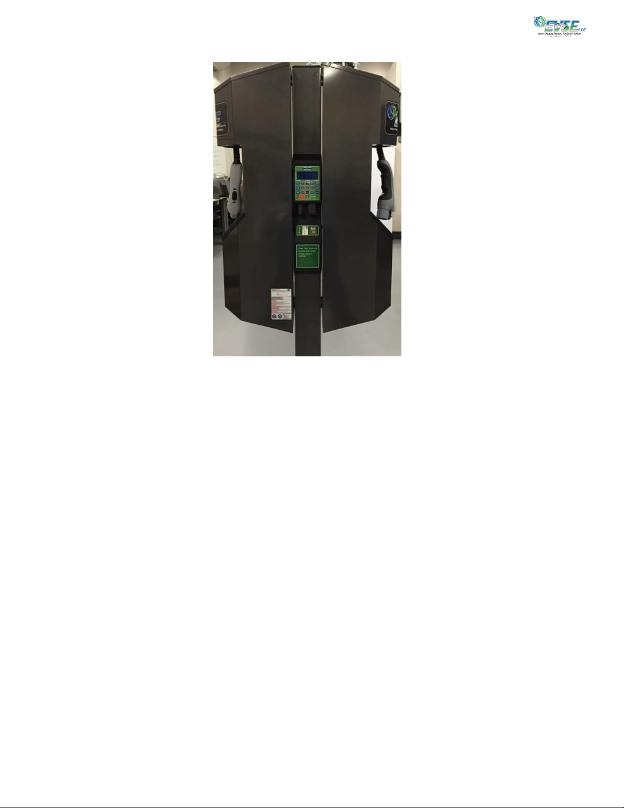
Figure 2 shows the location of the Payment Module when mounted on a dual 3704 EVSE.
3725-104 User Manual May 20, 2019
Page 7
Figure 2
3725-104 User Manual May 20, 2019

Page 8
Specifications
Product Code
Model 3725-104
Mounting: On EVSE Pole, Remote Pole or Wall
Communication to EVSE: ZigBee Mesh or Serial RS-232
Communication to Network: Ethernet or Cellular
Payment Method: Credit/Debit Card Magnetic Reader
RFID Reader (Optional)
Electrical
Voltage
Power Consumption
+24 VDC @ 1 amp
Less than 24 watts (Based on Configuration)
Hardware
CPU
Display
Keypad
Credit Card Reader
RFID Reader
Ethernet
ZigBee
Environmental
1 GHz
LCD, 4 rows, 20 alphanumeric characters per row
3x4 keypad, ½” keys on 5/8” centers, sealed, snap-dome
Encrypted
Mifare/iClass-compatible
IEEE 802.3 10Base-T and 802.3u 100Base-T
Frequency: 2.4 GHz
Operating Temp
Operating Humidity
NEMA Rating
Compliance
-22F to +122F (-30C to 50C) Ambient
0% to 90% non-condensing
3R
EMC
Accessories
Meets FCC Class A, Canadian ICES-003
Communication to EVSE (ZigBee)
Communication to Network
(Cellular Modem)
RFID Reader
General
Contains - FCC ID: MCQ-PROS2B, IC: 1846A-PROS2B (optional)
Contains - (V) FCC ID: N7N-SL5011, IC: 2417C-SL5011 (optional)
- (A) FCC ID: N7N-SL8090, IC: 2417C-SL8090 (optional)
Contains - FCC ID: JQ6-MCLASSRP10E, IC:2236B-MCLASSRP10E (optional)
Weight
Size
2.30 lbs.
4 in (W) x 17 9/16 in (H) x 2 1/2 in (D)
Product Code
*Observe all required Lockout/Tagout procedures while making any electrical connections or servicing the unit.
3725-104 User Manual May 20, 2019

Page 9
Network Payment Comm Mount
Options Options Options Options
Payment Module
Base Unit: 3725-104 x xx x xx
Cellular Communication Options (Ethernet Included)
Ethernet E
CDMA (Verizon) V
GSM (AT&T, Sim Card Customer Supplied) A
Payment Options
Insertion Mag Stripe Reader 09
Insertion Mag Stripe and iCLASS Readers 10
Insertion Mag Stripe and Blackboard VR100 Reader* 11
(*Includes 110 VAC/24 VDC pwr supply for ZigBee)
Communications Options
Serial S
ZigBee Z
Mounting Options
None (When mounted on EVSE pole as part of shipped assembly) xx
Pole (pole with Blackboard Reader Assembly, ZigBee) PB
Pole (standalone Pmt Mod with Pole w/ 24VDC power supply, for ZigBee comm) P1
Pole with 1-2 Mux (includes standalone Pmt Mod, 3x6 pole, 1-2 EVSE, serial) P2
Pole with 1-4 Mux (includes standalone Pmt Mod, 3x6 pole, 1-4 EVSE,serial) P3
Pole with 5-8 Mux (includes standalone Pmt Mod, 3x6 pole, 5-8 EVSE serial) P4
Wall (with Blacboard Reader Assembly, ZigBee) WB
Wall (Includes standard wall frame and 24 VDC power supply, ZigBee com) W1
Wall with 1-2 Mux (includes Pmt mod, wall frame, mux, 1-2 EVSE, serial) W2
Wall with 1-4 Mux (includes Pmt Mod, standard wall frame, mux, 1-4 EVSE, serial) W3
Wall with 5-8 Mux (includes Pmt Mod, standard wall frame, mux, 5-8 EVSE, serial) W4
KEY
PA = 3725-104-E-09-S-xx ….Payment Module (E,CC,S) PA (3725-A0400)
PB = 3725-104-E-10-S-xx …Payment Module (E,CC,RFID ICLASS,S) PB (3725-A0403)
PC = 3725-104-E-09-Z-xx …Payment Module (E,CC,ZigBee) PC (3725-A0404)
PD = 3725-104-E-10-Z-xx …Payment Module (E,CC,RFID ICLASS,ZigBee) PD (3725-A0405)
PE = 3725-104-V-09-S-xx .. Payment Module (CDMA Modem(V),CC,S) PE (3725-A0402)
PF = 3725-104-V-10-S-xx …Payment Module (CDMA Modem (V),CC,RFID ICLASS,S) PF (3725-A0401)
PG = 3725-104-V-09-Z-xx ..Payment Module (CDMA Modem (V),CC,ZigBee) PG (3725-A0406)
PH = 3725-104-V-10-Z-xx .. Payment Module (CDMA Modem (V),CC,RFID ICLASS,ZigBee) PH (3725-A0407)
PI = 3725-104-A-09-S-xx ..Payment Module (GSM Modem (A),CC,S) PI (3725-A0408)
PJ = 3725-104-A-10-S-xx ..Payment Module (GSM Modem (A),CC,RFID ICLASS,S) PJ (3725-A0409)
PK = 3725-104-A-09-Z-xx …Payment Module (GSM Modem (A),CC,ZigBee) PK (3725-A0410)
PL = 3725-104-A-10-Z-xx …Payment Module (GSM Modem (A),CC,RFID ICLASS, ZigBee) PL (3725-A0411)
3725-104 User Manual May 20, 2019

Page 10
LOCKOUT/TAGOUT
Warning: Disconnect power from service lines.
Avertissement: Déconnecter puissance de lignes de service.
Prior to performing electrical wiring for installation of the Gateway, ensure that power has been removed from the service
lines originating from the service panel.
To maintain the safety of all persons in the area a lockout/tagout procedure should be followed per 29 CFR 1910.147.
Lockout is the placement of a lockout device on the service panel energy isolation device (circuit breaker) to ensure that the
power source cannot be operated until the lockout device is removed. A lockout device utilizes a positive means such as a lo ck
(key or combination lock with a circuit breaker lockout) to hold the breaker in a safe position to prevent energization.
Tagout is the placement of a tagout device (a tag or other prominent warning device) on an energy isolation device to indicate
that the energy isolation device and the equipment being controlled may not be operated until the tagout is removed. The
tagout device should be non-reusable, attached by hand, self-locking and non-releasing with a minimum unlocking strength of
no less than 50 pounds.
The lockout approach shall be used unless the utilization of a tagout procedure will provide full personnel protection.
3725-104 User Manual May 20, 2019
Page 11
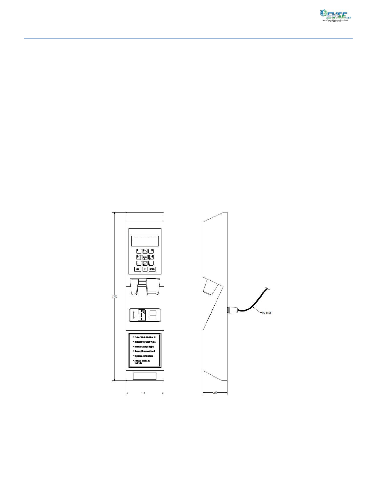
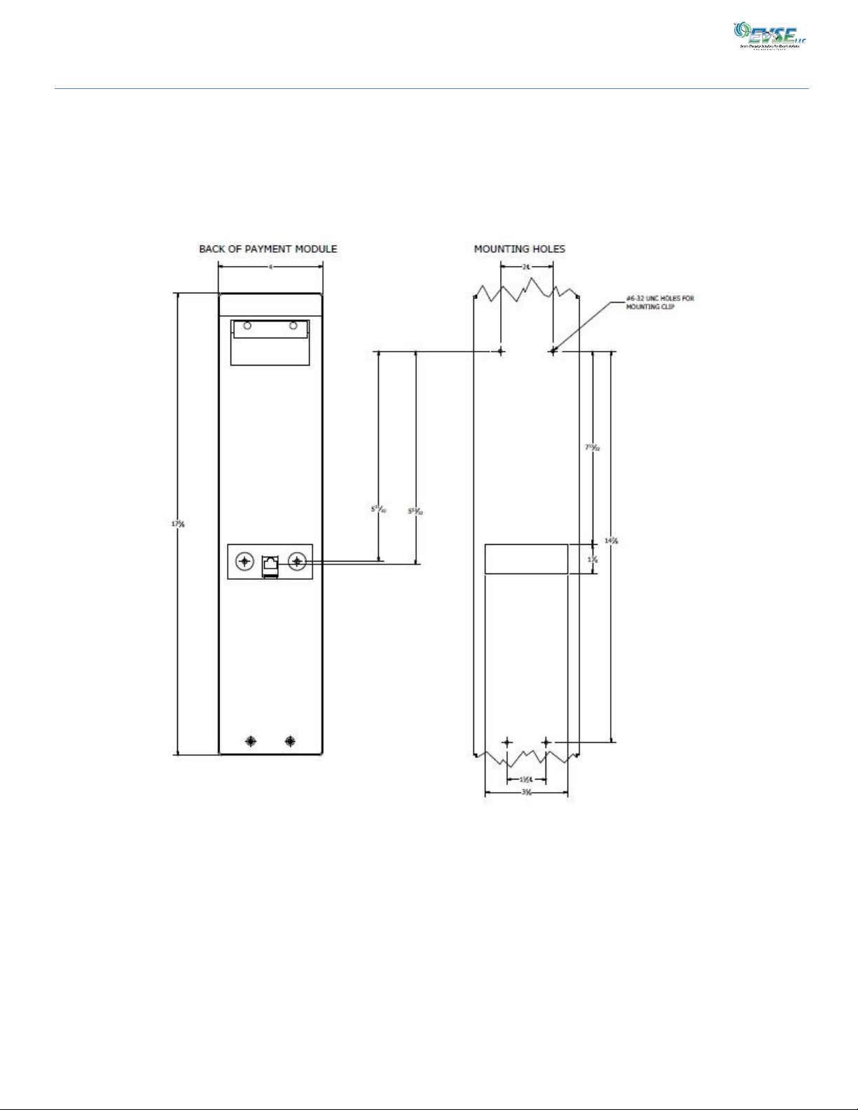
Installation Overview
The 3725-104 is shipped either mounted to an EVSE or optional ZigBee Mesh mounting pole, or can be configured for
mounting on a wall, with or without the optional ZigBee Mesh. The unit’s pole-mount dimensions and mounting pattern are
displayed below. For specific installation instructions, see the 3725 series of Installation Sheets.
Figure 3
3725-104 User Manual May 20, 2019
Page 12
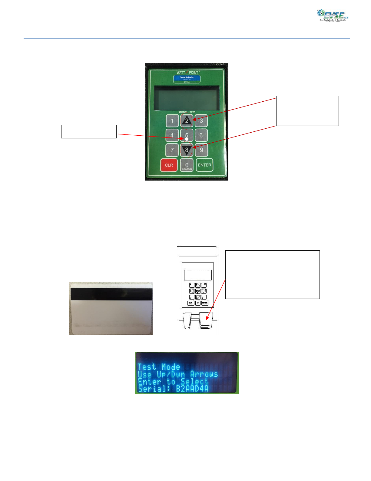
Payment Module Operation
Scrolls up and down
options
Magnetic Strip Read Here. Insert
the card with the entire white
side facing you and the black
strip facing the right side of the
reader.
Braille Centering
Keypad Overlay
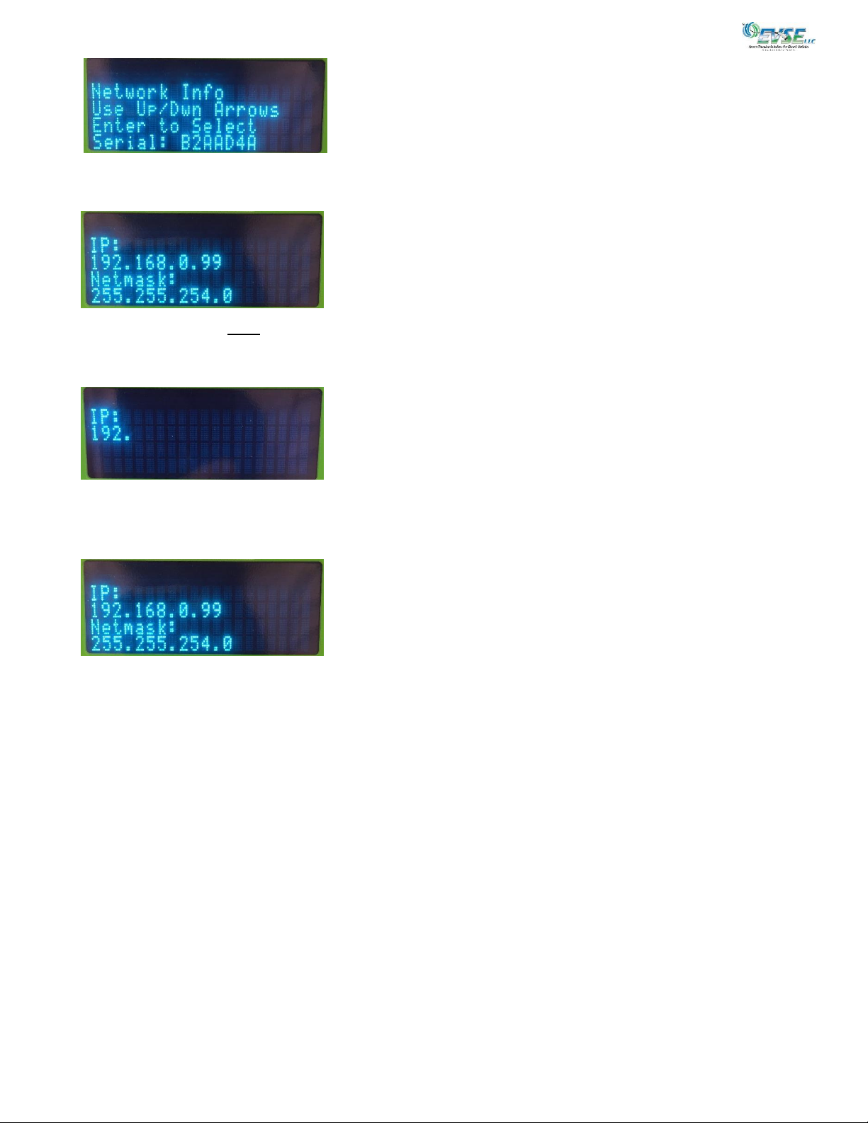
Changing the IP Address For Ethernet Connections
through display list
Unless the Payment Module’s IP Address was set specifically for your site at the factory, you might need to change the
address via the Module’s interface. The factory default address is 192.168.13.99.
1. Insert the test card that came with the Payment Module into the Magnetic Strip reader to put the module into test
mode.
2. Using the Payment Module’s Up and Down arrows, scroll through the choices until you display Network Info and
press Enter.
3725-104 User Manual May 20, 2019
Page 13
3. Using the Payment Module’s Up and Down arrows, scroll through the choices until you display IP Address and press
Enter.
4. Press Enter and enter a static IP address for this Payment Module. The numbers are in groups of four, with three
numbers possible in each group. If you fill in all three numbers, the system automatically adds a period (.). If you need to
enter less than three numbers in that group, press Enter to force the period (.).
5. After entering the entire IP address, press Enter.
6. Repeat this sequence of steps for all other required changes to Netmask, Gateway, and DNS. When you are done with all
changes, press Enter. The main IP Address screen displays with your changes.
7. Press Enter to accept these changes. The Payment Module automatically resets. This might take a few minutes.
3725-104 User Manual May 20, 2019
 Loading...