

查询PMR209供应商
PMR209
• RC unit, class X2, metallized paper with integrated resistor
• 0.047 – 0.47 µF, 22 – 470
ΩΩ
Ω, 250 VAC, +85 °C
ΩΩ
• Small dimensions
• Excellent self-healing properties.
Ensures long life even when subjected to
frequent overvoltages.
• High dU/dt capability.
• Self-extinguishing encapsulation.
• Good resistance to ionisation due
to impregnated dielectric.
TYPICAL APPLICATIONS CONSTRUCTION
RC unit for use in DC and AC applications
for:
– contact protection
– interference suppression of contacts
– transient suppression
Single layer metallized paper. Encapsulated
and impregnated in self-extinguishing
material meeting the requirements of UL 94V-
0. The resistance in the metal layer is
utilized as series resistance, integrated
resistor.
TECHNICAL DATA
Rated voltage
Capacitance range
Capacitance tolerance
Resistance range
Resistance tolerance
Peak pulse voltage
Temperature range
Climatic category
Approvals
Series resistance
250 VAC 50/60 Hz, 630 VDC
0.047 – 0.47 µF
± 20%
22 – 470 Ω
± 30%
1000 V
–40 to +85°C
40/085/56/B
S, N, D, FI, VDE, SEV, UL
The series resistance is defined at 1 kHz for RC ≥ 50 µs
and at 100 kHz for RC < 50 µs.
• The impregnated paper ensures
excellent stability giving outstanding
reliability properties, especially in
applications having continuous operation.
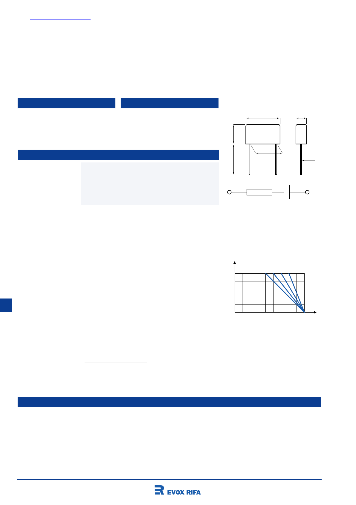
L
H
p ± 0.5
l
CR
d = 0.8 for p = 15.2 and 20.3
1.0 for p = 25.4
l: standard: 30 +5/-0 mm (code R30)
option: short leads, tolerance +0/-1 mm
(standard 6 mm, code R06)
Other lead lengths on request.
B
∅ d
Insulation resistance
Pulse current
Test voltage between
terminals
In DC applications
Power ratings
≥ 3000 MΩ for C ≤ 0.33 µF
≥ 1000 s for C > 0.33 µF
Measured at 500 VDC after 60 s, +23°C
Max 12 A repetitive. Max 20 A peak for occasional transients.
The 100% screening factory test is carried out at 1800
VDC. The voltage level is selected to meet the requirements
in applicable equipment standards. All electrical
characteristics are checked after the test.
Recommended voltage ≤ 630 VDC.
The average losses may reach 0.5 W provided the surface
P
max
W
0.5
0
40
Maximum allowable power dissipation vs
ambient temperature and case sizes.
123
50 60 70 80 85 °C
4
T
amb
temperature does not exceed + 85°C. For max. permitted
power dissipation vs temperature, see derating curves.
Curve Dimensions
1 B = 7.3
2 B = 7.6
3 B = 11.3
4 B = 15.3
ENVIRONMENTAL TEST DATA
Vibration IEC 60068-2-6, Test Fc 3 directions at 2 hour each No visible damage, No open or short circuit
10 – 500 Hz at 0.75 mm or 98 m/s
Bump IEC 60068-2-29, Test Eb 4000 bumps at 390 m/s
2
2
No visible damage, No open or short circuit
Solderability IEC 60068-2-20, Test Ta Solder globule method Wetting time for d ≤ 0.8 < 1 s
for d > 0.8 < 1.5 s
Active flammability EN 132400
Passive flammability IEC 60384-14 (1993), EN 132400
Humidity IEC 60068-2-3, Test Ca +40°C and 90 – 95% R.H. 56 days
196

ARTICLE TABLE
PMR209
Capaci- Resis- Max dimensions in mm reel Weight Approvals
tance tance R30 R06 taped Article code
µF
0.047 47 7.3 13.0 19.0 15.2 400 800 400 3.0 √√√√√√√ PMR209MB5470M047R30
0.047 100 7.3 13.0 19.0 15.2 400 800 400 3.0 √√√√√√√ PMR209MB5470M100R30
0.10 22 7.6 14.0 24.0 20.3 250 1500 250 4.0 √√√√√√√ PMR209MC6100M022R30
0.10 33 7.6 14.0 24.0 20.3 250 1500 250 4.0 √√√√√√√ PMR209MC6100M033R30
0.10 47 7.6 14.0 24.0 20.3 250 1500 250 4.0 √√√√√√√ PMR209MC6100M047R30
0.10 68 7.6 14.0 24.0 20.3 250 1500 250 4.0 √√√√√√√ PMR209MC6100M068R30
0.10 100 7.6 14.0 24.0 20.3 250 1500 250 4.0 √√√√√√√ PMR209MC6100M100R30
0.10 150 11.3 16.5 24.0 20.3 150 1500 180 7.0 √√√√√√√ PMR209MC6100M150R30
0.10 220 11.3 16.5 24.0 20.3 150 1500 180 7.0 √√√√√√√ PMR209MC6100M220R30
0.10 330 11.3 16.5 24.0 20.3 150 1500 180 7.0 √√√√√√√ PMR209MC6100M330R30
0.10 470 11.3 16.5 24.0 20.3 150 1500 180 7.0 √√√√√√√ PMR209MC6100M470R30
0.22 22 11.3 16.5 24.0 20.3 150 1500 180 7.0 √√√√√√√ PMR209MC6220M022R30
0.22 33 11.3 16.5 24.0 20.3 150 1500 180 7.0 √√√√√√√ PMR209MC6220M033R30
0.22 47 11.3 16.5 24.0 20.3 150 1500 180 7.0 √√√√√√√ PMR209MC6220M047R30
0.22 68 11.3 16.5 24.0 20.3 150 1500 180 7.0 √√√√√√√ PMR209MC6220M068R30
0.22 100 11.3 16.5 24.0 20.3 150 1500 180 7.0 √√√√√√√ PMR209MC6220M100R30
0.22 150 11.3 16.5 24.0 20.3 150 1500 180 7.0 √√√√√√√ PMR209MC6220M150R30
0.22 220 11.3 16.5 24.0 20.3 150 1500 180 7.0 √√√√√√√ PMR209MC6220M220R30
0.22 330 12.1 19.0 30.5 25.4 100 800 10.0 √√√√√√√ PMR209ME6220M330R30
0.22 470 15.3 22.0 30.5 25.4 75 600 15.0 √√√√√√√ PMR209ME6220M470R30
0.47 33 15.3 22.0 30.5 25.4 75 600 15.0 √√√√√√√ PMR209ME6470M033R30
0.47 47 15.3 22.0 30.5 25.4 75 600 15.0 √√√√√√√ PMR209ME6470M047R30
0.47 68 15.3 22.0 30.5 25.4 75 600 15.0 √√√√√√√ PMR209ME6470M068R30
0.47 100 15.3 22.0 30.5 25.4 75 600 15.0 √√√√√√√ PMR209ME6470M100R30
0.47 150 15.3 22.0 30.5 25.4 75 600 15.0 √√√√√√√ PMR209ME6470M150R30
0.47 220 15.3 22.0 30.5 25.4 75 600 15.0 √√√√√√√ PMR209ME6470M220R30
ΩΩ
Ω B H L p pcs pcs pcs g
ΩΩ
Quantity per package
SNDFIVDE
SEV
UL
APPROVALS/REFERENCE DOCUMENTS
Certification Body Specification Approval reference
S EN 132400 9528104
N EN 132400 P951 03084
D EN 132400 304424
Fl EN 132400 184789-01
VDE EN 132400 91805
SEV EN 132400 00-1929
UL UL 1283 E 100117
ORDERING INFORMATION
The article code for the standard part is given in the article table.
For other options, see page 21.
MARKING
• RIFA
• RIFA article code
• RC unit
• Rated capacitance and resistance
• Rated voltage
• X2
• SH, for self-healing
• Climatic category according to
IEC 60068-1, appendix A
• Passive flammability class
• Circuit diagram
• Manufacturing code (year, month)
PACKING
RC units in standard design (lead length 30
mm) and with L < 24 mm and lead length 5
or 6 mm are packed bulk in a box with
dimensions 245 x 145 x 80 mm. Quantity/
package as per article table. RC units with
L ≥ 24 mm and lead length 5 or 6 mm are
packed on trays piled in a box with
dimensions 300 x 260 x 195 mm.
Quantity/package as per article table.
Reels with taped capacitors are packed 10
in a box with dimensions 370 x 370 x 560
mm. The standard quantity/reel is for 360
mm reel. If 500 mm reel is required, it must
be specified when ordering and the
quantity is 2 x the given quantity.
197

WWW.ALLDATASHEET.COM
Copyright © Each Manufacturing Company.
All Datasheets cannot be modified without permission.
This datasheet has been download from :
www.AllDataSheet.com
100% Free DataSheet Search Site.
Free Download.
No Register.
Fast Search System.
www.AllDataSheet.com
 Loading...