

EVOX RIFA PEG 225 User Manual
RoHS
Compliant
PEG 225 up to 150°c
17.5±0.
5
Ø1±0.0
3
H
3.3±0.5
Ø16±0.5
�
0.8±0.1
15.24±0.1
• Up to 150°C
• High CV
• Extremely high ripple current
Up to 28 A ripple, RMS, Continuous load
• High vibration resistance
APPLICATION BASIC DESIGN
PEG 2 2 5 is a ne w generation o f high
performance axial electrolytic capacitors,
designed for automotive applications with
extremely high demands.
PEG 225 is an el e c t ro l y t ic ca p a c it o r
with outstanding electrical performance.
Polarized, all-welded design, tinned copper
wire leads, negative pole connected to the
case. The PEG 225 winding is housed in a
cylindrical aluminium can with a high purity
alum inium lid and a high quality rubber
SPECIFICATION
Standards IEC 60384-4 Long Life
Grade 40/125/56
Capacitance range 470 - 6300 µF
Capacitance tolerance –10 to +30%, –20 to +20%–20 to +20%20 to +20%
Rated voltage 25 – 63 VDC– 63 VDC 63 VDC
Temperature range –40 to +125°C at U
–40 to +150°C at reduced voltage
R
Shelf life at 0V +105°C 5000 h,
+40°C 10 years
Diameter range 16 - 20 mm
Resistance to vibrations 10 - 2000 Hz, 1.5 mm
displacement amplitude or
max 20 g 3x22 hours
The capacitors must be clamped by the body.
Life test 2000 h, 150°C (Ø20 case)
1500 h, 150°C (Ø16 case)
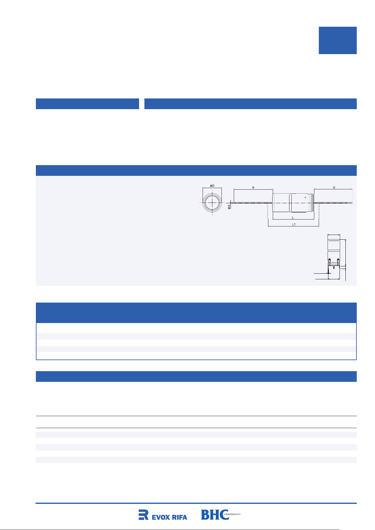
Dimensions table PEG 225 (mm)
gasket. Low ESR is a result of a low resistive
electrolyte/paper system and an all-welded
design. Thanks to its mechanical robustness
the PEG 225 is suitable for use in mobile
and in aircraft installations, operation up to
150°C.
Remark:
Capacitor in standard version
is without insulation. Polyester
insulation on request
Radial version
See page 39
D x L Case D d L L1 b±2 Weight
code ±0.5 ± 0.03 ±1 min Box approx (g)
16 × 27 F 16 1.0 26.5 33 40 8
16 × 35 G 16 1.0 34.5 41 40 11
20 × 27 H 20 1.0 26.5 33 40 13
20 × 35 J 20 1.0 34.5 41 40 20
20 × 43 L 20 1.0 42.5 49 40 24
ARTICLE TABLE PEG 225 (150°C)
CR D × L I
Tc=125°C Tc=140°C Tc=150°C Ta=125°C Ta=125°C 20°C 20°C 125-150°C code
≥ 5 kHz ≥ 5 kHz ≥ 5 kHz ≥ 5 kHz ≥ 5 kHz 100 Hz 100 kHz 5-100 kHz
µF mm A A A A A mW mW mW
* I
RAC
** I
RAC
** I
RAC
*** IAC(max)**** ESR (max) ESR (max) ESR (max) Article
RAC
25 VDC (UR ) [150 °C at UDC ≤ 18 V]
2200 16x27 17.3 11.0 4.9 6.1 7.7 60 34 11.9 PEG225HF4220M
3000 16x35 19.7 12.5 5.6 7.4 9.4 44 25 9.2 PEG225HG4300M
3600 20x27 23.5 14.9 6.7 7.6 9.6 38 22 9.4 PEG225HH4360Q
4800 20x35 26.7 16.9 7.6 9.2 11.7 28 16 7.3 PEG225HJ4480Q
6300 20x43 28.3 17.9 8.0 10.2 12.9 24 14 6.5 PEG225HL4630Q
* Capacitor mounted with low thermal resistance path (heat-sink). Maximum ripple current continuous operation.
** Valid for capacitor supplied with reduced DC voltage, up to 18 VDC. Capacitor mounted with low thermal resistance path.
*** Rated ripple current, continuous operation at natural convection (∅20 case 4000 h, ∅16 case 3000 h).
**** Max ripple current, at natural convection and reduced voltage (∅20 case 2000 h, ∅16 case 1500 h)
35
PEG 225
ARTICLE TABLE PEG 225 (150°C)
CR D × L I
Tc=125°C Tc=140°C Tc=150°C Ta=125°C Ta=125°C 20°C 20°C 125-150°C code
≥ 5 kHz ≥ 5 kHz ≥ 5 kHz ≥ 5 kHz ≥ 5 kHz 100 Hz 100 kHz 5-100 kHz
µF mm A A A A A mW mW mW
* I
RAC
** I
RAC
** I
RAC
*** IAC(max)**** ESR (max) ESR (max) ESR (max) Article
RAC
40 VDC (UR ) [150 °C at UDC ≤ 32 V]
1200 16x27 16.6 10.5 4.7 5.8 7.4 80 36 13.0 PEG225KF4120M
1800 16x35 19.3 12.2 5.5 7.2 9.2 55 25 9.6 PEG225KG4180M
2000 20x27 22.8 14.4 6.5 7.3 9.3 50 23 10.0 PEG225KH4200Q
3000 20x35 25.8 16.3 7.3 8.9 11.3 35 17 7.8 PEG225KJ4300Q
3900 20x43 27.7 17.5 7.8 10.0 12.7 28 14 6.8 PEG225KL4390Q
63 VDC (UR ) [150 °C at UDC ≤ 54 V]
470 16x27 12.1 7.7 3.4 4.2 5.3 156 52 24.3 PEG225MF3470Q
680 16x35 13.8 8.7 3.9 5.3 6.7 109 37 18.7 PEG225MG3680Q
900 20x27 18.0 11.4 5.1 5.8 7.3 86 31 16.1 PEG225MH3900Q
1400 20x35 20.9 13.2 5.9 7.3 9.2 57 22 11.9 PEG225MJ4140Q
1800 20x43 22.8 14.4 6.5 8.3 10.5 45 18 10.0 PEG225ML4180Q
* Capacitor mounted with low thermal resistance path (heat-sink). Maximum ripple current continuous operation (see below).
** Valid for capacitor supplied with reduced DC voltage, capacitor mounted with low thermal resistance path.
*** Rated ripple current, continuous operation at natural convection (∅20 case 4000 h, ∅16 case 3000 h).
**** Max ripple current, at natural convection (∅20 case 2000 h, ∅16 case 1500 h)
RIPPLE CURRENT SPECIFICATION AND OPERATIONAL LIFE
The ripple current specification (see table
above) is given at case temperature (Tc)
and at ambient temperature (Ta). To be able
FREQUENCY
100 Hz 300 Hz 1 kHz 5 kHz 100 kHz
to operate at specified ripple current at
temperature Tc, the capacitor needs to be
mounted with low thermal resistance path
to application chassis.
Correction factor (Corr) 0.35 0.57 0.80 1.00 1.04
(Typical value)
Frequency correction factor, for ripple
current (Corr), see table to the right:
For operational life time calculation, please
see pages 148 to 149.
RELIABILITY
Estimated field failure rate: < 2 ppm/year.
The expected failure rate, for this capacitor
range, is based on field experience for capacitors with structural similarity. This failure
rate is valued during first year of operation.
Rated leakage current, IRL (µA)
Rated voltage, UR (V)
Rated capacitance, CR (µF)
I
RL
LEAKAGE CURRENT
= 0.003 x CR x UR + 4
Expected failure rate thereafter: < 1 ppm/y.
(Until end of specified operational life)
ORDERING INFORMATION
For further ordering information please see page 8.
P E G 2 2 5 H F 4 2 2 0 M E 1
1 2 3 4 5 6 7 8 9 10 11 12 13 14 15 16 17 18 19 20
Capacitance tolerances: E1: Packed in boxes
Pos. 13: Q: –10 to +30%
M: -20 to +20%
Quantities and weights
CASE CODE F G H J L
Weight approx (g) 8 11 13 20 24
Standard box quantity 125 100 150 125 100
36
 Loading...