

Page 1

WALLACE & TIERNAN® MEASUREMENT AND CONTROL
SYSTEM
DEPOLOX
®
POOL
INSTRUCTION MANUAL
Page 2

2 WT.050.570.000.DE.IM.0714
DEPOLOX® Pool
Please note
Original manual!
Page 3

DEPOLOX® Pool
WT.050.570.000.DE.IM.0714 3
Contents
Part 1
Operation 5
1.1 Safety Notes . . . . . . . . . . . . . . . . . . . . . . . . . . . . . . . . . . . . . . . . . . . . . . . . . . . . . . . . . . . . 7
1.1.1 Intended Use. . . . . . . . . . . . . . . . . . . . . . . . . . . . . . . . . . . . . . . . . . . . . . . . . . . . . . . . . . . .7
1.1.2 Cautionary Notes and Symbols. . . . . . . . . . . . . . . . . . . . . . . . . . . . . . . . . . . . . . . . . . . . . .7
1.1.3 General Principles. . . . . . . . . . . . . . . . . . . . . . . . . . . . . . . . . . . . . . . . . . . . . . . . . . . . . . . .8
1.1.4 Notes for the Operator and Operating Personnel . . . . . . . . . . . . . . . . . . . . . . . . . . . . . . . . 8
1.1.5 Guarantee conditions . . . . . . . . . . . . . . . . . . . . . . . . . . . . . . . . . . . . . . . . . . . . . . . . . . . . .9
1.1.6 Personnel Selection and Qualification . . . . . . . . . . . . . . . . . . . . . . . . . . . . . . . . . . . . . . . . 10
1.1.7 Safety Instructions during Specific Operating Phases. . . . . . . . . . . . . . . . . . . . . . . . . . . .10
1.1.8 Notes on Special Dangers. . . . . . . . . . . . . . . . . . . . . . . . . . . . . . . . . . . . . . . . . . . . . . . . .11
1.2 Description. . . . . . . . . . . . . . . . . . . . . . . . . . . . . . . . . . . . . . . . . . . . . . . . . . . . . . . . . . . . .13
1.2.1 Versions. . . . . . . . . . . . . . . . . . . . . . . . . . . . . . . . . . . . . . . . . . . . . . . . . . . . . . . . . . . . . . .13
1.2.2 Design . . . . . . . . . . . . . . . . . . . . . . . . . . . . . . . . . . . . . . . . . . . . . . . . . . . . . . . . . . . . . . . .14
1.2.3 Function. . . . . . . . . . . . . . . . . . . . . . . . . . . . . . . . . . . . . . . . . . . . . . . . . . . . . . . . . . . . . . .19
1.2.4 Controller modes for chlorine control. . . . . . . . . . . . . . . . . . . . . . . . . . . . . . . . . . . . . . . . .23
1.2.5 Combinations of controller modes. . . . . . . . . . . . . . . . . . . . . . . . . . . . . . . . . . . . . . . . . . .26
1.3 Operation. . . . . . . . . . . . . . . . . . . . . . . . . . . . . . . . . . . . . . . . . . . . . . . . . . . . . . . . . . . . . .29
1.3.1 Display and Operating Elements. . . . . . . . . . . . . . . . . . . . . . . . . . . . . . . . . . . . . . . . . . . .29
1.3.2 Notes on Operation . . . . . . . . . . . . . . . . . . . . . . . . . . . . . . . . . . . . . . . . . . . . . . . . . . . . . .33
1.3.3 Menu Structure . . . . . . . . . . . . . . . . . . . . . . . . . . . . . . . . . . . . . . . . . . . . . . . . . . . . . . . . . 35
1.3.4 Calibration . . . . . . . . . . . . . . . . . . . . . . . . . . . . . . . . . . . . . . . . . . . . . . . . . . . . . . . . . . . . .64
1.3.5 Setting Overview - Specifications . . . . . . . . . . . . . . . . . . . . . . . . . . . . . . . . . . . . . . . . . . .70
1.4 Errors. . . . . . . . . . . . . . . . . . . . . . . . . . . . . . . . . . . . . . . . . . . . . . . . . . . . . . . . . . . . . . . . .75
1.5 Maintenance . . . . . . . . . . . . . . . . . . . . . . . . . . . . . . . . . . . . . . . . . . . . . . . . . . . . . . . . . . . 81
Part 2
Installation and Commissioning 85
2.1 Scope of Supply . . . . . . . . . . . . . . . . . . . . . . . . . . . . . . . . . . . . . . . . . . . . . . . . . . . . . . . .87
2.2 Technical Data. . . . . . . . . . . . . . . . . . . . . . . . . . . . . . . . . . . . . . . . . . . . . . . . . . . . . . . . . .89
2.2.1 Electronic module . . . . . . . . . . . . . . . . . . . . . . . . . . . . . . . . . . . . . . . . . . . . . . . . . . . . . . . 89
2.2.2 Flow block assembly . . . . . . . . . . . . . . . . . . . . . . . . . . . . . . . . . . . . . . . . . . . . . . . . . . . . .91
2.2.3 Sensor measuring modules. . . . . . . . . . . . . . . . . . . . . . . . . . . . . . . . . . . . . . . . . . . . . . . .92
2.3 Transport, Storage. . . . . . . . . . . . . . . . . . . . . . . . . . . . . . . . . . . . . . . . . . . . . . . . . . . . . . .95
2.4 Installation . . . . . . . . . . . . . . . . . . . . . . . . . . . . . . . . . . . . . . . . . . . . . . . . . . . . . . . . . . . . .97
2.5 Defining the Application. . . . . . . . . . . . . . . . . . . . . . . . . . . . . . . . . . . . . . . . . . . . . . . . . .101
2.6 Functions. . . . . . . . . . . . . . . . . . . . . . . . . . . . . . . . . . . . . . . . . . . . . . . . . . . . . . . . . . . . .107
2.6.1 Controller Types and Control Parameters. . . . . . . . . . . . . . . . . . . . . . . . . . . . . . . . . . . .107
2.6.2 Alarms . . . . . . . . . . . . . . . . . . . . . . . . . . . . . . . . . . . . . . . . . . . . . . . . . . . . . . . . . . . . . . .116
2.6.3 Adaption (only applies for free Cl
2
) . . . . . . . . . . . . . . . . . . . . . . . . . . . . . . . . . . . . . . . . .118
2.6.4 Special Functions . . . . . . . . . . . . . . . . . . . . . . . . . . . . . . . . . . . . . . . . . . . . . . . . . . . . . .123
2.6.5 Interfaces. . . . . . . . . . . . . . . . . . . . . . . . . . . . . . . . . . . . . . . . . . . . . . . . . . . . . . . . . . . . .124
Page 4

DEPOLOX® Pool
4 WT.050.570.000.DE.IM.0714
2.7 Installation / Commissioning . . . . . . . . . . . . . . . . . . . . . . . . . . . . . . . . . . . . . . . . . . . . . .127
2.7.1 Filling Cell Sand. . . . . . . . . . . . . . . . . . . . . . . . . . . . . . . . . . . . . . . . . . . . . . . . . . . . . . . . 134
2.7.2 Inserting and Connecting the Sensors . . . . . . . . . . . . . . . . . . . . . . . . . . . . . . . . . . . . . .135
2.7.3 Connecting the Sample Water. . . . . . . . . . . . . . . . . . . . . . . . . . . . . . . . . . . . . . . . . . . . .137
2.7.4 Fitting the Fine Filter . . . . . . . . . . . . . . . . . . . . . . . . . . . . . . . . . . . . . . . . . . . . . . . . . . . .142
2.7.5 Connecting the Device to the Power Supply. . . . . . . . . . . . . . . . . . . . . . . . . . . . . . . . . . 143
2.7.6 Mounting the Labelling Field . . . . . . . . . . . . . . . . . . . . . . . . . . . . . . . . . . . . . . . . . . . . . .144
2.7.7 Mounting the Housing Covers. . . . . . . . . . . . . . . . . . . . . . . . . . . . . . . . . . . . . . . . . . . . . 145
2.7.8 Switching the device on. . . . . . . . . . . . . . . . . . . . . . . . . . . . . . . . . . . . . . . . . . . . . . . . . . 145
2.7.9 Ym Calibration. . . . . . . . . . . . . . . . . . . . . . . . . . . . . . . . . . . . . . . . . . . . . . . . . . . . . . . . . 147
2.8 Taking the Device Out of Operation . . . . . . . . . . . . . . . . . . . . . . . . . . . . . . . . . . . . . . . . 149
2.9 Replacing a Fuse or Battery . . . . . . . . . . . . . . . . . . . . . . . . . . . . . . . . . . . . . . . . . . . . . . 151
2.10 Installation of DEPOLOX® Pool electronics module with other flow cell modules . . . . . 153
2.10.1 DEPOLOX® Pool electronics module with DEPOLOX® 5 flow cell module. . . . . . . . . . 153
2.10.2 DEPOLOX® Pool electronics module with DEPOLOX® 4 flow cell module. . . . . . . . . . 154
2.11 Sensor Measuring Modules and Spare Parts . . . . . . . . . . . . . . . . . . . . . . . . . . . . . . . . . 155
2.12 Wiring diagrams. . . . . . . . . . . . . . . . . . . . . . . . . . . . . . . . . . . . . . . . . . . . . . . . . . . . . . . . 163
2.13 Certificates. . . . . . . . . . . . . . . . . . . . . . . . . . . . . . . . . . . . . . . . . . . . . . . . . . . . . . . . . . . . 171
Index. . . . . . . . . . . . . . . . . . . . . . . . . . . . . . . . . . . . . . . . . . . . . . . . . . . . . . . . . . . . . . . .175
Page 5

DEPOLOX® Pool
WT.050.570.000.DE.IM.0714 5
1 Part 1 Operation
Part 1
Operation
Page 6

DEPOLOX® Pool
6 WT.050.570.000.DE.IM.0714
Page 7
DEPOLOX® Pool Safety Notes
WT.050.570.000.DE.IM.0714 7
1.1 Safety Notes
1.1.1 Intended Use
The DEPOLOX® Pool is exclusively designed for measurement and
control purposes for the treatment of water in swimming pools and
baths.
The DEPOLOX
®
may only be used in buildings and under the operating
conditions described in the technical data.
The device is not designed for any application other than that described
in this manual
– this is contrary to its intended use!
Compliance with the intended use of this device also includes reading
this operating manual and observance of all instructions which it contains, particularly the safety instructions. Furthermore all inspection and
maintenance work must be performed at the prescribed intervals.
If the device is not employed in accordance with its intended use, safe
and reliable operation cannot be guaranteed.
The operator is solely responsible for any personal injury or damage to
property resulting from employment of the device which is contrary to
its intended use! The operator is obliged to keep the device in proper
working order.
1.1.2 Cautionary Notes and Symbols
The following descriptions and symbols are used in this operating manual to indicate hazards, mandatory instructions and notes:
WARNING!
This symbol indicates a directly impending hazard which can be
fatal or result in very serious injury.
WARNING!
This symbol warns against parts carrying dangerous electrical
voltages.
Risk of fatal injury!
CAUTION!
This symbol indicates situations which can cause damage to the device
itself or surrounding equipment.
NOTE
This symbol indicates tips for the operator and other particularly useful
information.
Page 8

Safety Notes DEPOLOX® Pool
8 WT.050.570.000.DE.IM.0714
1.1.3 General Principles
This device corresponds to the state of the art and recognised tech-
nical safety regulations!
This device contains inherent hazards for personnel and equip-
ment! These hazards are related to live components or incorrect
dosing of chemicals.
Always observe the safety instructions and hazard notes!
Only use this device in accordance with its intended purpose!
Faults which can negatively affect safety must be remedied imme-
diately!
1.1.4 Notes for the Operator and Operating Personnel
Notes for the
operator
This operating manual and the technical documentation of the in-
stalled device components must always be available at the installation site!
Always observe any supplementary, generally valid legal regulati-
ons or other binding rules and ensure their compliance! These rules
and regulations concern, for example:
- Work safety
- Accident prevention
- Environmental protection
- Hygiene
-First aid
All personnel charged with installation, commissioning, operation,
maintenance and repair of the device must read and understand
this operating manual, in particular the safety instructions!
Never attempt to perform any modifications, extensions or conver-
sions on the device which could have an adverse affect on safety
without the written approval of the manufacturer!
Only use spare parts which have been approved by the manufac-
turer. This is always guaranteed when original spare parts are
purchased.
Always observe the intervals for regular maintenance or inspection
work which are either prescribed or stated in the operating manual.
CAUTION!
The system must not be used with flammable liquids or dangerous or
toxic gazes.
Page 9

DEPOLOX® Pool Safety Notes
WT.050.570.000.DE.IM.0714 9
NOTE
The safety instructions in the technical documentation for installed device components must also be observed!
Notes for
operating personnel
Before starting operation of this device always read the operating
manual, in particular the safety instructions!
Never employ any working methods which could endanger safety!
Always comply with the prescribed values for sample water admis-
sion pressure, connection voltage and ambient and operating conditions!
Never deactivate any safety features!
During operation of the device there is the risk of unexpected in-
correct functions resulting from failure or errors of the control system.
In the event of such safety-relevant changes in the operating performance of the device, switch it off immediately and remedy the
fault or have it remedied immediately!
When the device is switched off, external voltage may still be ap-
plied.
Always eliminate or have eliminated any leakage on the flow block
assembly immediately!
In the event of a fire always switch the device off with the external
main switch or the external main circuit breaker or fuse!
1.1.5 Guarantee conditions
The following must be observed for compliance with guarantee
conditions:
Installation, commissioning by Evoqua technicians or trained and
authorised specialised personnel, e.g. of contracted companies
Conform to the intended use.
The operation parameters and settings must be met.
The system may only be operated by instructed personnel.
A works journal must be kept.
Use of approved calibration solutions
The system should always be protected against frost.
Execution of maintenance work by operating personnel
Use of original spare parts
If any of the above conditions are not met, the guarantee is revoked.
Page 10

Safety Notes DEPOLOX® Pool
10 WT.050.570.000.DE.IM.0714
1.1.6 Personnel Selection and Qualification
Only authorised personnel may operate or perform any work on the
device!
Only employ reliable and trained or instructed personnel!
Always clearly define competence of personnel for installation, ope-
ration, maintenance and repair!
Assign responsibility . The operating perso nnel must be able to refu-
se to act upon instructions of third parties which are contrary to the
safety regulations!
1.1.7 Safety Instructions during Specific Operating
Phases
Normal operation Never employ any working methods which could affect safety!
Only run the device when the housing is closed!
Inspect the device at least once daily for externally visible damage
and faults! Inform the responsible person/authority immediately of
any detected changes (including any changes in the operating performance)!
In the event of functional faults always switch the device off imme-
diately! Have faults remedied immediately!
Installation and
maintenance work
Always perform installation or maintenance work in accordance
with this operating manual or the technical documentation for installed device components!
Secure the device against activation during installation and mainte-
nance work!
Always retighten released screw connections!
Never use corrosive cleaning agents!
For cleaning only use a damp cloth.
Ensure safe disposal of agents and replaced parts in accordance
with environmental regulations!
Page 11

DEPOLOX® Pool Safety Notes
WT.050.570.000.DE.IM.0714 11
1.1.8 Notes on Special Dangers
Electrical power Only use original fuses with the prescribed current rating! In the
event of a fault in the electrical power supply, switch the device off
immediately!
Only qualified electricians or trained personnel supervised by a
qualified electrician are permitted to perform any work on electrical
components in accordance with valid electrotechnical regulations.
If stipulated, disconnect all parts of the device from the power sup-
ply before performing any inspection, maintenance or repair work.
Then first test the disconnected components to ensure they do not
carry any voltage.
Inspect/check the electrical system of the device regularly. Remedy
any faults immediately!
Connect disconnected cables in accordance with the terminal dia-
gram!
Agents and
chemical substances
When handling agents and chemical substances always observe
the safety regulations valid for each product!
Always remove leaked agents immediately with a suitable binde r or
wipe up with a cloth. Danger of slipping!
Always collect and dispose of agents or used cleaning material se-
parately and in accordance with valid national regulations!
Page 12

Safety Notes DEPOLOX® Pool
12 WT.050.570.000.DE.IM.0714
Page 13

DEPOLOX® Pool Description
WT.050.570.000.DE.IM.0714 13
1.2 Description
1.2.1 Versions
Versions The DEPOLOX® Pool is available in different versions:
With a non-pressurised flow block assembly
With a pressurised flow block assembly
each for
200...240 V AC (can be switched over to 100-120 V AC)
24 V DC
The non-pressurised and pressurised versions vary in that a different
number of sensors can be installed and also with regard to the design
of the sample water outlet (refer to section 1.2.2 Design). The nonpressurised version is used when the sample water is freely discharged. With the pressurised version the sample water is returned to the
system circuit.
Page 14

Description DEPOLOX® Pool
14 WT.050.570.000.DE.IM.0714
1.2.2 Design
Overall design The DEPOLOX® Pool is of modular design.
The flow block assembly (1, Bild 1) and the electronic module (3) are
the two main components.
Up to five sensor measuring modules (2) can be installed in the
DEPOLOX
®
Pool, depending on the version.
Fig. 1 DEPOLOX
®
Pool
1 2 3
Page 15

DEPOLOX® Pool Description
WT.050.570.000.DE.IM.0714 15
Flow block assembly The flow block assembly (Bild 2) has a plastic housing (2) with a remo-
vable cover.
The housing contains all components of the flow block assembly:
The cell body with cover (1)
The flow control valve (3)
The multi-sensor (8)
The drain (5)
The fine filter (7) (only when membrane sensors are used)
The sample water inlet with check valve and ball valve (6)
The sample water outlet (4) (on pressurised version with ball valve)
The top clips (10) for the sensor and the lower clips (9) for accommodating the buffer or calibration solution can be mounted on the outside
of the housing.
Two mounts are provided for the lower clips.
The cell body can be equipped with up to five sensors (1) on the non-
pressurised version or four sensors on the pressurised version.
Fig. 2 Flow block assembly (cover removed)
11
10
9
8
7
6
1
2
3
4
5
Page 16
Description DEPOLOX® Pool
16 WT.050.570.000.DE.IM.0714
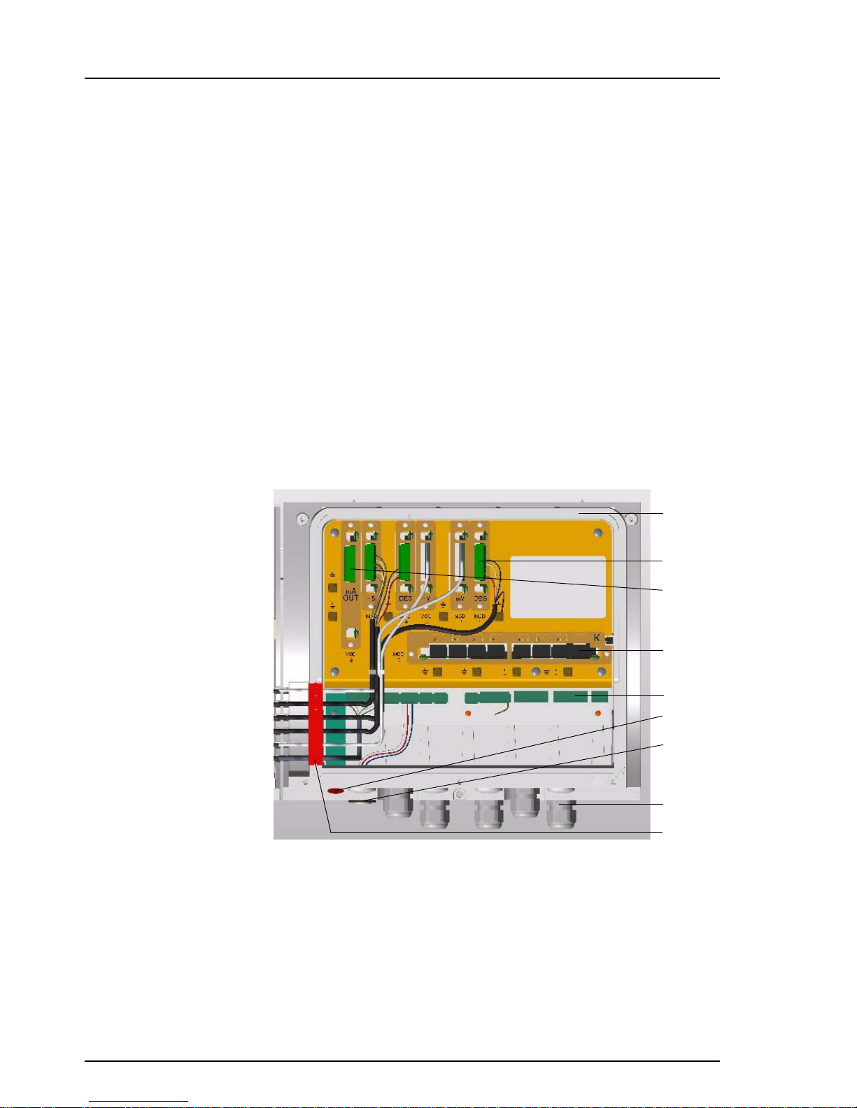
Electronic module The electronic module (Bild 3) has a plastic housing (1) with removable
cover.
The housing contains:
The motherboard with power unit and five slots (2) for the cards of
the sensor measuring modules
The relay card (4)
The plug-in card with analog outputs (3) (option)
The terminal strip (5)
The housing ducts for the cables of the sensor measuring
modules (9)
The following are incorporated into the base of the housing:
The infra-red interface (6)
The RS232 interface (7)
The cable terminal screws (8)
Fig. 3 Electronic module (cover removed)
1
2
3
4
5
6
7
8
9
Page 17
DEPOLOX® Pool Description
WT.050.570.000.DE.IM.0714 17
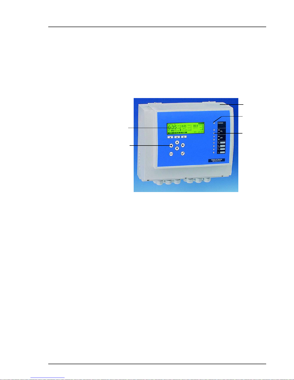
The following are integrated into the cover (1, Bild 4):
The graphic display (5)
The operating elements (4)
A green LED (2) for indication of the power supply
Eight red LEDs (3) for indication of operating conditions
Fig. 4 Electronic module
1
2
3
5
4
Page 18

Description DEPOLOX® Pool
18 WT.050.570.000.DE.IM.0714
Sensor measuring mo-
dule
A sensor measuring module (Bild 5) comprises:
The sensor (3)
The sensor cable (1) with watertight housing cable duct (2)
The pre-calibrated plug-in card (4)
Due to the modular design, simple retrofitting and configuration of sensor measuring modules in accordance with the plug-and-play principle
is possible at any time (refer to section 2.7.2).
Fig. 5 Sensor measuring module, example
The following sensor measuring modules are available:
Cl2
pH
Redox
Cl-N
Conductivity
1
2
4
3
Page 19

DEPOLOX® Pool Description
WT.050.570.000.DE.IM.0714 19
1.2.3 Function
Overall function Up to seven measured values can be indicated by specific process
components:
Free chlorine*
Combined chlorine*/Total chlorine*
pH value*
Redox potential
Conductivity*
Temperature
The value of the combined chlorine is calculated from the difference
between the total chlorine and the free chlorine.
The graphic display shows the measured data, limit values and setpoints as numeric values, diagrams or a trend line.
All measured values can be displayed at the same time. The pre-set limit values meet the requirements of DIN 19643 "Treatment of water of
swimming-pools and baths".
Flow block assembly The flow block assembly guarantees a stable measurement signal with
Robust sensors
Constant sample water flow rate with the aid of the flow control val-
ve
Hydrodynamic sand cleaning of the chlorine sensor measuring
electrodes
Optimum flow around all sensors
The multi-sensor integrated into the flow block assembly monitors the
constant sample water flow rate, registers the sample water temperature and ensures wide-spread equipotential grounding (sample water
grounding).
* These measurements are automatically temperature-compensated.
Page 20

Description DEPOLOX® Pool
20 WT.050.570.000.DE.IM.0714
Electronic module The electronic module serves for the visualisation and subsequent pro-
cessing of the measured data as well as process control.
Positioners or various dosing pumps can be connected to the control
outputs of the process control unit.
The following functions are possible:
Dosing of the disinfectant
Adaptation of the control parameters to the circulation
(ECONOMIC operating mode)
Correction of the pH value
Control of the activated powder carbon or UV disinfection unit
Addition of the flocculant (controlled by circulation and the pH va-
lue)
Up to four relay outputs can also be used as alarm contacts. They can
be freely configured. Multiple allocation of events is possible.
The following special functions are also integrated into the control unit:
The DIN contact
Flocculation control
DIN contact The unit contains a DIN contact. If the set hygiene parameters are met,
this information is forwarded to the swimming pool control unit:
Cl2 0.3 ... 0.6 mg/l
pH 6.5 ... 7,6
Redox > 750 mV
Cl-N < 0.2 mg/l
These limits can be freely set.
Adaption programme The adaption programme automatically determines the control para-
meters for free chlorine during commissioning.
Page 21

DEPOLOX® Pool Description
WT.050.570.000.DE.IM.0714 21
Safety functions The safety functions integrated into the control unit are:
Safety cut-out if the circulation fails and/or if the dosing tank signals
that it is empty and also if the sample water supply fails
Dosing time monitoring and the dosing time delay
Alarms
External stop for all controllers
Function "positioner closed" in the event of power failure
(only with external power supply for positioner)
Password protection on two levels
Infrared calibration Infrared calibration is performed in conjunction with the photometer
P42 i-cal. The measured calibration value is automatically transmitted
at the correct time with infrared light.
ECONOMIC
operating mode
If circulation is reduced when required, for example during the night,
the device switches to ECONOMIC operating mode when it is set accordingly. The control parameters for chlorine and flocculation are automatically adapted. To this purpose the device uses a second set of
parameters.
Links The control unit of the DEPOLOX
®
Pool supports the following links:
CMS 2.2:
Visualisation software for archiving and display of measured values
on PCs with Windows operating systems
SECO-S7:
PLC driver for data links to Siemens PLC, type S7-300
OPC Server Data Access V2.0:
Server software for Windows operating systems for data links to visualisation system with OPC client capability
ChemWeb server:
Measured value archiving and display, remote diagnosis, remote
access with standard browser with Internet and e-mail capability
Process control system of different manufacturers
(refer to the manual "RS-485 Bus Interface" for description, specification and protocol)
Applications Process adaptation with four pre-configured settings (application 1 to 4)
Page 22

Description DEPOLOX® Pool
22 WT.050.570.000.DE.IM.0714
Controller types The following controller types are firmly integrated into the DEPOLOX
®
Pool and can be selected according to applications 1 to 4:
Cl
2
pH mS Cl-N
Positioner without feedback signal
XX
Positioner with feedback signal X
Solenoid diaphragm metering
pump
XXX
Dosing pump X X X
Analog output dosing equipment X X X
Cl-N release contact for
activated powder carbon or
UV disinfection unit
X
Control of a flocculant dosing unit
Page 23
DEPOLOX® Pool Description
WT.050.570.000.DE.IM.0714 23
1.2.4 Controller modes for chlorine control
From firmware version 2.0 of the DEPOLOX® Pool, there are two options
for setting the concentration of disinfectant:
Cl2-Single feedback closed loop control
In this mode, the required Cl2 value is held at the setpoint using the
PI single feedback closed loop control (standard chlorine
regulation).
CEDOX control
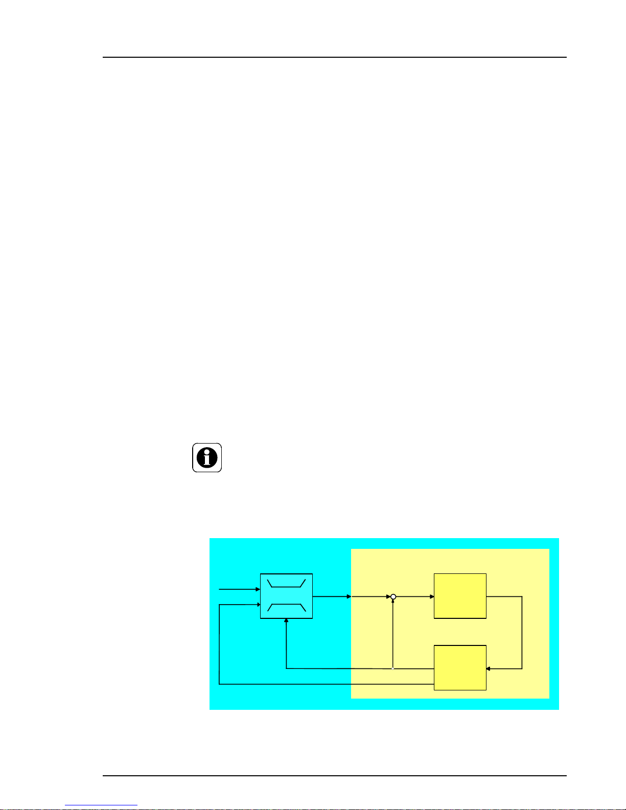
In this mode, the chlorine setpoint is continuously optimised using a
PI single feedback closed loop control in order to maintain a constant redox value. For this procedure, the setpoint entered is not Cl2
as normal, but the required redox potential is set as the setpoint.
A specially developed CEDOX mode calculates the amount of free
chlorine required in the water based on the demand. This internal
chlorine setpoint is used to measure the required quantity of disinfectant using the PI single loop feedback controller.
The variable or optimised Cl2 setpoint must remain between the
“Min setpoint” and “Max setpoint” limit values (Menu 1.1.4).
DIN 19643 specifies the following Cl2limits:
Min = 0.30 mg/l and Max = 0.60 mg/l.
Requirement for CEDOX control:
- Chlorine measuring and control
- pH measuring and control
- mV measuring
NOTE
CEDOX control only works if the pH value deviates from the pH setpoint
by no more than 0.30
The CEDOX control system is based on the following principle:
Cl2
PI controller
Xd
deviation
Swimming-
pool
Control loop
X
Chlorine
value
Y
Dosage rate
W
Chlorine
setpoint
Former chlorine control loop
X
Redox value
W
Redox
setpoint
Chlorine Max
Chlorine Min
X
Chlorine value
Characteristic line
system
CEDOX System
Page 24
Description DEPOLOX® Pool
24 WT.050.570.000.DE.IM.0714
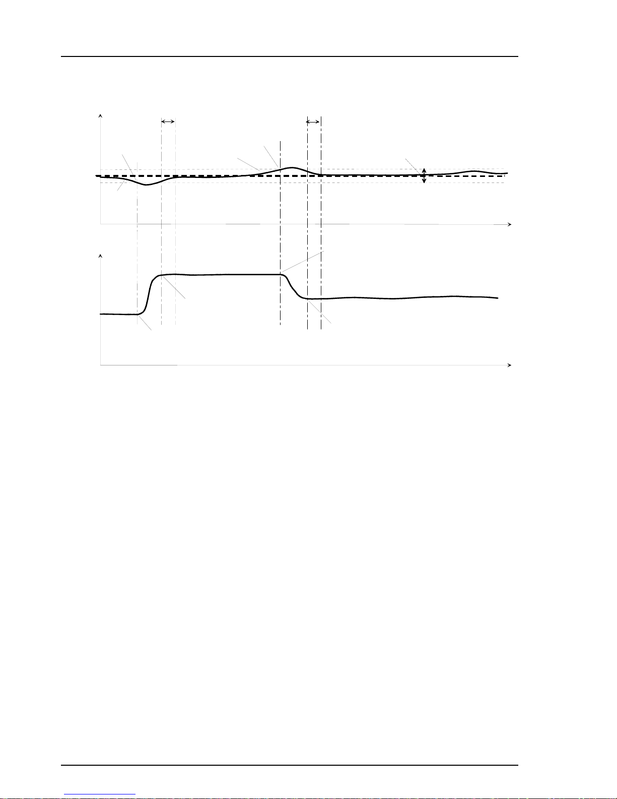
The example diagram below shows how the CEDOX mode works:
Notes for settings for CEDOX control:
The parameter "mV delay time” (Menü 1.3.1) defines the reaction times
of the redox electrode and has a delaying effect on the setpoint optimisation of the chlorine control.
The Cl2 setpoints determined by the CEDOX mode must always be
between the limit values Cl2 min setpoint" and "Cl2 max setpoint". If
these setpoint limits are reached, the mV measured value may vary
from the mV setpoint.
Notes for startup/calibration of CEDOX control
After calibrating the redox electrode, the setpoint optimisation is out of
service for 2 hours, as the redox electrode does not supply reliably signals during this period. During this time, the DEPOLOX
®
Pool uses a
fixed temporary Cl2 setpoint. This temporary Cl2 setpoint is the last
current Cl2 before the calibration (can be altered manually, Menu 2.1.1
or 2.1.3).
When the chlorine measuring is calibrated, the DEPOLOX
®
Pool auto-
matically calculates a new Cl2 setpoint if deviations are detected.
m V s e t p o i n t
m V s e t p o i n t + X s h
m V s e t p o i n t - X s h
m V d e l a y t i m e
b e l o w
m V s e t p o i n t
C l 2 s e t p o i n t i n c r e a s e s
w h e n t h e m e a s u r e d v a l u e i s b e l o w
m V s e t p o i n t
T h e n e w i n c r e a s e d C l 2 s e t p o i n t
i s r e a c h e d
m V d e l a y t i m e
T h e n e w r e d u c e d C l 2 s e t p o i n t
i s r e a c h e d
c o n t a m i n a t i o n
d e c r e a s e s
T i m e t
m V
C l 2
m V n e u t r a l b a n d
a b o v e
m V s e t p o i n t
C l 2 s e t p o i n t d e c r e a s e s
w h e n t h e m e a s u r e d v a l u e i s a b o v e
m V s e t p o i n t
c o n t a m i n a t i o n
i n c r e a s e s
Page 25

DEPOLOX® Pool Description
WT.050.570.000.DE.IM.0714 25
What can be achieved by using CEDOX?
Reduction of disinfectant consumption
(as much chlorine as necessary and as little chlorine as is possible).
The optimum control of the Cl2 setpoint based on the redox potenti-
al means that the lowest possible Cl2 setpoint is always used and
thus disinfectant saved.
Extension of reduced operation leads to longer energy saving times
and increased savings on energy and water.
If the circulation is reduced, which is controlled using the DIN va-
lues, the automatic increase in the chlorine content can keep the
redox potential in the good range for longer and thus extend the reduction of the circulation.
Attention: However, this can lead to increased disinfectant consumption
Optimising the water quality, especially in swimming pools with
heavy fluctuations in usage (e.g. outdoor pools) or with long periods
of no usage.
NOTE
CEDOX does not mean that disinfection systems can be made smaller!
Page 26

Description DEPOLOX® Pool
26 WT.050.570.000.DE.IM.0714
1.2.5 Combinations of controller modes
DEPOLOX® Pool gives you the option of running various controller modes in combination with ECO mode.
The operator can select four different controller modes:
Cl2 single feedback
closed loop control
Normal mode: Cl
2 setpoint
ECO mode: Cl
2 setpoint ECO
Cl2 setpoint: In this mode, the required Cl2 value is held at the setpoint
using the PI single feedback closed loop control.
Setting parameters: Xp, Tn, setpoint
The flocculent control system measures at a constant rate.
Cl2 setpoint
ECO: In ECO mode, the reduced Cl2 value is held at the
setpoint using the PI single feedback closed loop control. There is a
digital input to switch the system to ECO mode.
ECO setting parameters: Setpoint
ECO, XpECO, TnECO
The flocculent control system measures at a constant rate.
This ECO mode can also be used for disinfectant control in combination with reduction of the circulation.
CEDOX Normal mode: CEDOX
ECO mode: CEDOX
ECO
(Version 2.00 and higher)
CEDOX:
In this mode, the setpoint entered is not Cl2 as normal, but
the required redox potential is set as the setpoint. The specially developed CEDOX mode calculates the amount of free chlorine required in
the water based on the demand. This internal Cl2 setpoint is used to
measure the required quantity of disinfectant using the PI single loop
feedback controller.
Setting parameters: Redox setpoint, Xp, Tn
The flocculent control system measures at a constant rate.
CEDOX ECO:
In CEDOX ECO mode, the mode is also controlled
based on a redox setpoint. There is a digital input to switch the system
to ECO mode. The device calculates the required concentration of free
chlorine in the water based on load and controls this Cl
2 setpoint using
the PI single loop feedback control.
Setting parameters: Redox setpoint
ECO, XpECO, TnECO
The flocculent control system measures at a constant rate.
This ECO mode can also be used for disinfectant control in combination with reduction of the circulation.
Page 27

DEPOLOX® Pool Description
WT.050.570.000.DE.IM.0714 27
Cl2 + CEDOXECO Normal mode: Cl2
ECO mode: CEDOX
ECO
(Version 2.00 and higher)
Cl2:
In this mode, the Cl2 setpoint is controlled by a PI single feedback
closed loop control.
Setting parameters: Xp, Tn, Cl2 setpoint,
The flocculent control system measures at a constant rate.
CEDOX ECO:
In CEDOX ECO mode, the mode is controlled based on
the mV setpoint (see under CEDOX). There is a digital input to switch
the system to ECO mode.
Setting parameters: Redox setpoint
ECO, XpECO, TnECO
The flocculent control system measures at a constant rate.
This ECO mode can also be used for disinfectant control in combination with reduction of the circulation.
Peak-chlorination
This function is primarily an addition in combination with CEDOX control when low concentrations of chlorine occur frequently.
The “peak-chlorination” function can guarantee pool hygiene, even
when the chlorine values are low and DIN parameters are complied
with, it can also ensure the prevention of algae growth.
At a maximum of 5 freely definable times per week, the DEPOLOX
®
Pool automatically adjusts to a higher chlorine value, which can even
be set to above the measurement range. These times can be repeated
weekly, or every two, three or four weeks.
The duration of the peak-chlorination can be defined and starts when
the peak-chlorination setpoint is reached.
For safety reasons, the system includes a time limit which defines the
maximum time for which this peak-chlorination value can be activated.
If the peak-chlorination value is not reached during this time, the process is cancelled and an error message is displayed.
Switching off
peak chlorination
There is the option of switching off the alarm and the overall chlorine
control during peak-chlorination. Once the Cl
2 value is back at the set-
point, the alarm and the total chlorine control are reactivated.
Adaption
The adaption menu (1.1.6) contains the parameters for Tu, Ts, Tu
ECO
and TsECO. Depending on the mode in which the adaption run is carried out, the relevant times are calculated (in normal mode Tu and Ts
and in ECO mode Tu
ECO and TsECO). At the same time, the times
determined are used to calculate the control parameters Xp, Tn or
XP
ECO und TnECO.
All the times and control parameters can also be entered manually if
they are known. If the times Tu and Ts or Tu
ECO and TsECO are
adjusted manually, the corresponding control parameters Xp and Tn
or. Xp
ECO and TnECO are calculated at the same time.
Page 28

Description DEPOLOX® Pool
28 WT.050.570.000.DE.IM.0714
Page 29

DEPOLOX® Pool Operation
WT.050.570.000.DE.IM.0714 29
1.3
1.3 Operation
1.3.1 Display and Operating Elements
Graphic display and
operating panel
All information is shown on the graphic display (Fig. 6) .
The DEPOLOX
®
Pool is operated with nine keys (Fig. 7).
With the top three keys the software controls the function (softkeys).
The exact depiction of the individual parameters on the graphic display
is described in the section 1.3.3 "Menu structure".
Fig. 6 Basic display (in the graphic display)
Fig. 7 Operating panel
m g / l
6 . 8 5
7 0 5
0 . 0 0
1 . 0 0
0 . 4 3
4 . 0 0
9 . 0 0
7 . 0 0
4 0 0
p H
m V
9 0 0
0 . 6 5
1 2 : 3 5
M O D E
C A L
M E N U
D I
I
D I
I I
D I
I I I
E C O
P O O L 1
1 0 0 % 2 8 . 4 ° C
1 3 s
Page 30

30 WT.050.570.000.DE.IM.0714
Operation DEPOLOX® Pool
1.3
Indicating elements
System name
Digital inputs 1, 2, 3 active
The symbols indicate that a function has been selected for the digital
signal and that a signal is applied.
Password active
The defined password must be entered to permit modification of parameters and for calibrating the device.
"ECONOMIC" operating mode active
The system is running with the second set of parameters (e. g. when
circulation is reduced).
Operating mode "Peak chlorination": Setpoint peak chlorination is active.
Flashing: Dosing is stopped until the normal chlorine setpoint is reached
again.
Time
"AUTO" operating mode active
The control unit is running in automatic mode.
Dosing is performed automatically.
"MANUAL" operating mode active
Dosing can be set manually.
"System stopped" operating mode
Dosing is switched off.
"Adaption" operating mode active during "Automatic" operation
Automatic determination of the control parameters for free chlorine is
active.
"Adaption" operating mode active during "Manual" operation
Automatic determination of the control parameters for free chlorine is
active.
Bar graph
This serves to indicate a measured value, the measuring range (column height), the limit values ( and ) a well as the setpoint ( )
POOL 1
D I
I
D I
I I
D I
I I I
E C O
12.35
S T O P
A
A
Page 31

DEPOLOX® Pool Operation
WT.050.570.000.DE.IM.0714 31
1.3
Softkeys
Indication of the current assignment of the softkeys.
Stop the adaption procedure.
Select one or more options from the list provided.
Change the operating mode.
Confirm your selection.
Select the "Calibration" menu.
Activate password protection.
Select a menu.
Select the "Mode" menu.
Start deactivation of password protection.
Move up one level.
A further sub-menu is available (e.g. when the DIN function is activated)
Feed delay
The time until dosing resumes after interruption.
Positioner feedback (Ym)
Feedback only applies for free chlorine.
To compensate for tolerances and possible positioner restrictions the
feedback display must be aligned.
Alignment can be performed either automatically or manually (refer to
the section 1.3.4 Calibration).
Sample water temperature
Error indication active (display bottom right)
The system has detected an error. The error can be specified with the
table in section 1.4. The number combination states the series number
of the error message and the total number of error messages (in this
case the first error of a total of five).
Display number (display bottom right)
This number enables allocation to a menu and stipulates the sequence
within the menu.
- - - - Blanks
Blanks serve to indicate when a value cannot be displayed (e.g. no sensor measuring module installed).
STOP
SELECT
CHANGE
ENTER
CAL
LOCK
MENU
MODE
UNLOCK
BACK
- - >
13s
100%
28.4°C
m A ? 1 / 5
1.1.2
Page 32
32 WT.050.570.000.DE.IM.0714
Operation DEPOLOX® Pool
1.3
Dosing and alarm indi-
cation
LED The nine LEDs are another indicating element. The significance of the
eight red LEDs depends on the selected application. This determines
whether control output or alarm is selected. The significance is marked
on the labelling strip to the right of the LED. The green LED lights up
when the device is in operation (POWER).
General messages Adaption is running!
This message appears if an attempt is made during adaption to automatically calibrate the positioner.
This function is possible in the manual mode only!
This message appears, for example, if an attempt is made to calibrate
the positioner during automatic operation. Acknowledge by pressing
ENTER or the ESC key.
A module was removed!
Do you wish to take over this configuration?
This message appears when the device is switched on after removal of
a module. Acknowledge with the yes/no key.
New hardware component found!
This message appears when the device is switched on after addition of
a module.
NOTE
Information on the plug-in cards which are contained in the device
are displayed in "Analog scan" when it is switched on or can be
viewed statically in the "Diagnosis" menu, item "Software Version"
(Display 1.8.5).
Operating elements
Softkey
Activate the function shown on the graphic display with the keys.
Up
Move up one level.
Display the previous option.
Increase the value.
Down
Move down one level.
Display the next option.
Decrease the value.
Left/right
Change the column in the menu.
Change the position in the displayed value (cursor menu).
Move forwards or backwards by seven hours in the line diagram.
Page 33
DEPOLOX® Pool Operation
WT.050.570.000.DE.IM.0714 33
1.3
Escape
Cancel the entry without saving the new value.
Move up one menu level.
Acknowledge
Acknowledge alarm message
Set the running delays to zero.
Delete adaption error.
Acknowledge max. dosing time to reactivate dosing.
1.3.2 Notes on Operation
During operation observe the following points:
Check your entry and modifications before exiting the menu.
Only press the keys with your fingers, never with hard or pointed
objects such as pencils etc. This could damage the sealed keypad.
Password The system runs with up to two passwords to ensure protection against
unauthorised or inadvertent incorrect operation:
The system password permits full access to all setting options.
The calibration password only permits access to the calibration
menu and the display of the menus.
Each password comprises a four-digit number combination.
NOTE
The password is not set at the works (four zeros).
A calibration password can only be set if a system password has
been set.
If the password protection was not activated with the "LOCK" soft-
key after entry/calibration, the system is automatically locked one
hour later.
The password can be changed after correct entry of the existing
password.
ESC
Page 34
34 WT.050.570.000.DE.IM.0714
Operation DEPOLOX® Pool
1.3
Operation You have the following options starting from the basic display:
Switching between the basic display/line diagrams
Press the up or down key
Select the area of operation
To select the menu press the
"MENU" softkey
For calibration press the "CAL"
softkey
To set the operating mode
press the "MODE" softkey
In the menu display select a
menu item
Select the menu item with the
arrow keys (arrow in front of
menu item)
Confirm the selection with
"ENTER"
Change/enter displayed parameters
Select the parameter with the
arrow keys (arrow in front of
parameter)
Confirm the selection with
"ENTER"
Change/enter the display with
the up or down key
Confirm the entry with
"ENTER"
Cancel entry Press the "ESC" key to exit the
menu item. Entries which have
not been confirmed are reset to
their original settings.
Reactivate password protection This function is only active when
a password has been programmed.
Change/enter displayed para-
meter
Block the system entry with the
"LOCK" softkey in the menu
display
Exit the menu item
Press the "ESC" key
or
Press the "BACK" softkey
Page 35

DEPOLOX® Pool Operation
WT.050.570.000.DE.IM.0714 35
1.3
1.3.3 Menu Structure
The DEPOLOX® Pool has 11 different menus:
Main menu
Calibration
Mode
Cl
2
settings
pH settings
Redox settings
Cl-N settings
Conductivity settings
System
Inputs/Outputs
Diagnosis
The "Calibration" and "Mode" menus are opened with the corresponding keys directly from the basic display. All other menus can be accessed with the "MENU" softkey.
The following pages show the 11 individual menus.
The displays contain the settings made at the works. If options are available for individual parameter values, these are listed to the right of the
illustration of the display information.
NOTE
The actual displays on your device can vary from those illustrated.
The displays depend on the number of sensor measuring modules
installed and the selected settings.
The display numbers are featured on the bottom right of the display .
These numbers are frequently referred to in the following section.
Page 36

36 WT.050.570.000.DE.IM.0714
Operation DEPOLOX® Pool
1.3
Main menu
Fig. 8 Main menu
6 , 8 5
0 , 5 2
6 8 0
1 7 , 2
0 , 3 5
m g / l
p H m V m g / l m S / c m
E S C
m g / l
0 , 0 0
1 . 0 0
0 . 4 3
0
0 . 5 0
0 . 1 0
0
2 0 . 0
0 , 6 5
1 2 : 3 5
P O O L 1
1 0 0 % 2 8 ° C
M O D E
C A L
M E N U
1 0 0 % 2 8 ° C
1 2 : 3 5
P O O L 1
C l2 f r e e
C l
2
t o t
M O D E
C A L
M E N U
D IID IIID I
II I
D IID IIID I
II I
0 . 0 0
P O O L 1
1 . 0 0
E S C
1 8 . 0 5 . 0 2
M O D E
C A L
M E N U
4 . 0 0
P O O L 1
9 . 0 0
E S C
M O D E
C A L
M E N U
0
9 0 0
E S C
M O D E
C A L
M E N U
p H
1 8 . 0 5 . 0 2
P O O L 1
m V
1 0 1 1 1 2
C l 2 f r e e
0
5 0
E S C
M O D E
C A L
M E N U
P O O L 1
° C
D IID IIID I
II I
D IID IIID I
II I
D I
I
D IIID I
II I
D IID IIID I
II I
7 8 9
1 0 1 1 1 2
7 8 9
1 0 1 1 1 2
7 8 9
1 0 1 1 1 2
7 8 9
m g / l
6 , 8 5
7 0 5
0 , 0 0
1 . 0 0
0 . 4 3
4 . 0 0
9 . 0 0
7 . 0 0
4 0 0
p H m V
9 0 0
0 , 6 5
1 2 : 3 5
P O O L 1
1 0 0 % 2 8 ° C
M O D E
C A L
M E N U
D IID IIID I
II I
E S C
0 , 5 2
m g / l
C l
2
t o t
1 7 , 2
m S / c m
= > 3 , 8 5
N a C l g / l
= > 3 , 8 5
N a C l g / l
E C O
1 8 . 0 5 . 0 2
1 8 . 0 5 . 0 2
1 3 s
E C O
E C O
E C O
E C O
E C O
E C O
W & T 0 0 0 2 5 E
Basic display 1
Basic display 2
Basic display 3
Line diagram 1
Line diagram 2
Line diagram 3
Line diagram 4
Page 37

DEPOLOX® Pool Operation
WT.050.570.000.DE.IM.0714 37
1.3
Main menu
Basic display 1 Top status line
System name (define in display 1.6.1)
Digital inputs activated (select function in display 1.7.5)
Password protection activated (set in display 1.6.2)
ECONOMIC parameter activated (select in display 1.7.5)
Time (set in display 1.6.1)
Peak chlorination is active (select in display 1.1.7)
Centre display range
Mode
Free chlorine (mg/l)
pH value (pH)
Redox potential (mV)
Bottom status line
Softkey display
Feed delay (s) (set in display 1.6.2)
e.g. after sample water stop or change of mode from manual to automatic. During this time the DI-I display and the stop message in
the display flash.
Error message (instead of positioner feedback, temperature and
feed delay)
In the case of several error messages the display alternates.
Positioner feedback Cl
2
(%)
Sample water temperature (°C)
Basic display 2
(if sensor measuring mo-
dule Cl-N and/
or conductivity provided)
Top status line
See basic display 1
Centre display range
Mode
Free chlorine (mg/l)
Total chlorine (mg/l) or
combined chlorine
(can be selected in display 1.4.3)
Conductivity (mS/cm) and additionally the
concentration of the NaCl in % or g/l
(can be selected in display 1.5.4)
Bottom status line
See basic display 1
Digital display
Bar graph
Digital display
Bar graph
Page 38

38 WT.050.570.000.DE.IM.0714
Operation DEPOLOX® Pool
1.3
Basic display 3 Top status line
See basic display 1
Centre display range
All existing measurements
Bottom status line
See basic display 1
Line diagrams
(4 max.)
Top status line
System name
Digital inputs activated
Password protection activated
Measurement parameters (can be selected in display 1.6.3)
ECONOMIC parameter activated
Date of the displayed diagram (set in display 1.6.1)
Error message
Centre display range
7-hour line diagram (can be scrolled back by up to seven days)
Bottom line
Softkey display
NOTE
When the line diagram is moved, the programmed values of the displayed period of time are also displayed when moving up or down one
level in the displays.
Return to the current display period by pressing "ESC".
Page 39

DEPOLOX® Pool Operation
WT.050.570.000.DE.IM.0714 39
1.3
Page 40

40 WT.050.570.000.DE.IM.0714
Operation DEPOLOX® Pool
1.3
Calibration
(Menu 2.1)
Fig. 9 Calibration
C a l . z e r o p o i n t
C a l . D P D
T e m p o r a r y S e t p .
C a l . p H 7
C a l . p H
O f f s e t p H
C a l . a t t e m p . 1 6 ° C
C a l i b r a t i o n
C a l i b r a t i o n C l 2
C a l i b r a t i o n p H
B A C K
E S C
B A C K
E S C
C a l i b r a t i o n C l - N
B A C K
E S C
C a l . m V 6 8 0 m V
T e m p o r a r y S e t p .
C a l i b r a t i o n O R P
B A C K
E S C
B A C K
E S C
C a l i b r . T e m p e r a t u r
C a l . µ S / c m 6 0 . 9 m S / c m
C a l . ° C
C a l i b r . C o n d u c t i v i t y
C A L .
m g / l
6 , 8 5
7 0 5
0 , 0 0
1 . 0 0
0 . 4 3
4 . 0 0
9 . 0 0
7 . 0 0
4 0 0
p H
m V
9 0 0
0 , 6 5
1 2 : 3 5
M O D E
C A L
M E N U
P O O L 1
1 0 0 % 2 8 ° C
C l 2
p H
R e d o x
C l - N
C o n d u c t i v i t y
T e m p e r a t u r e
0 , 0 5
m g / l
3 , 9 µ A
6 8 5
m V
6 7 7 m V
6 , 8 5
p H
- 2 0 m V
C a l . t o t a l 0 . 0 0 m g / l
C a l . c o m b i n e d
0 , 8 2
m g / l
6 0 , 2
m S / c m
c a l . ° C 2 5 , 0 ° C
2 4 , 9
° C
2 4 , 0 ° C
B A C K
E S C
B A C K
E N T E R
B A C K
E N T E R
B A C K
E N T E R
B A C K
E N T E R
B A C K
E N T E R
B A C K
E N T E R
B A C K
E N T E R
D IID IIID I
II I
2 . 1
2 . 1 . 1
2 . 1 . 6
2 . 1 . 2
2 . 1 . 3
2 . 1 . 4
2 . 1 . 5
L O C K
E N T E R
B A C K
0 , 2 0 0 m A
0 , 2 0 µ A
Basic display
Calibration
Calibration Cl
2
Calibration pH
Calibration ORP
Calibration Cl-N
Calibr. conductivity
Calibr. temperature
Page 41

DEPOLOX® Pool Operation
WT.050.570.000.DE.IM.0714 41
1.3
Calibration
(Menu 2.1)
Basic display Refer to main menu
Calibration Display of all available calibration options
Calibration Cl
2
(refer to section 1.3.4)
Cal. zero point with softkey "ENTER" the display is set to
"0.00 mg/l"
Cal. DPD within measuring range
Temporary Setp. refer to Calibration ORP
Calibration pH
(refer to section 1.3.4)
Cal. pH 7.00 6.85 ... 7.15 pH
Cal. pH within measuring range
Offset pH -1.00 ... +1.00 pH
Cal. at temp. 00 ... 50 °C
Calibration ORP
(refer to section 1.3.4)
Cal. mV within measuring range
Temporary Setp. Temporary setpoint until 2 hours after
ORP calibration
(only with CEDOX control)
Calibration Cl-N
Enter free Cl
2
within measuring range
Cal. total within measuring range
Cal. combined within measuring range
Calibr. conductivity
Cal. mS/cm within measuring range
Cal. °C 00.0 ... 50.0 °C
Calibr. temperature
Cal. °C 00.0 ... 50 °C
Page 42
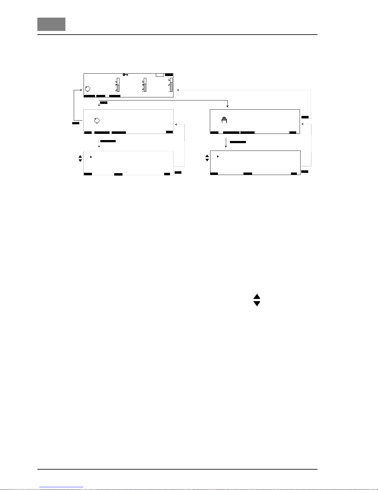
42 WT.050.570.000.DE.IM.0714
Operation DEPOLOX® Pool
1.3
Mode
(Menu 3)
Basic display Refer to main menu
Automatic/Manual
AUTO / MANUAL switch over with the "CHANGE" softkey
Setpoints
Cl
2
within measuring range
Cl
2
Eco within measuring range
pH within measuring range
max.comb. chlorine within measuring range
Conductivity within measuring range
Dosing rate MANUAL
Cl
2
Positioner with Ym Open / Closed
Position positioner %
Positioner without Ym Open / Closed
Dosing pump 2P;
Pulse pump 2P;
Analog output controller 2P000 ... 100 %
pH
Positioner without Ym Open / Closed
Dosing pump 2P;
Pulse pump 2P;
Analog output controller 2P000 ... 100 %
Dosing pump 3P;
Pulse pump 3P;
Analog output controller 3P-100 ... +100 %
Cl-N Off / On
Conductivity 000 ... 100 %
Flocculation 000 ... 100 %
C a n g e M o d e
3
M O D E
3
D o s i n g r a t e M A N U A L
E S C
3 . 1
E S C
C H A N G E S E T P O I N T
A U T O
C h a n g e M o d e
M A N U A L
H A N D D O S
C l2 - - - Y m 3 4 %
p H 0 0 0 %
C l - N o f f
C o n d u c t i v i t y 0 0 0 %
F l o c c u l a t i o n 0 0 0 %
S e t p o i n t s
E S C
3 . 1
C l2
0 . 5 5 m g / l
C l2 - E c o 0 . 3 0 m g / l
p H 7 . 0 0 p H
m a x . c o m b . C h l o r 0 . 8 0 m g / l
C o n d u c t i v i t y 6 8 0 µ S / c m
E S C
S E T P O I N T
m g / l
6 . 8 5
7 0 5
0 . 0 0
1 . 0 0
0 . 4 3
4 . 0 0
9 . 0 0
7 . 0 0
4 0 0
p H
m V
9 0 0
0 . 6 5
1 2 : 3 5
P O O L 1
1 0 0 % 2 8 ° C
M O D E
C A L
M E N Ü
D IID IIID I
II I
E C O
1 3 s
B A C K
B A C K
B A C K
B A C K
B A C K
B A C K
B A C K
B A C K
E N T E R
E N T E R
H A N D D O S
C H A N G E
Fig. 10 Mode settings
Page 43

DEPOLOX® Pool Operation
WT.050.570.000.DE.IM.0714 43
1.3
Description of the
operating modes
MANUAL In the MANUAL mode dosing is not automatically controlled. The va-
lues must be continuously monitored.
The MANUAL mode is used:
In the event of any possible system faults
During maintenance/cleaning work or while checking the system
NOTE
The system password is required to change the settings.
When the MANUAL mode is set:
The pumps are off, the positioner remains in its current position, if
necessary unlock the positioner and close either by hand or with
the Handdos menu.
AUTOMATIC Automatic control of chlorine, pH, combined chlorine, conductivity and
addition of flocculant
AUTO with ECO Control of the chlorine value and flocculation is performed in accor-
dance with the ECO parameter set if the Economic parameter is activated with DI 2 or 3.
STOP The STOP mode is automatically activated:
When the sample water flow is faulty
When a stop signal is received via the digital inputs
After activation:
The pumps switch off, the positioner closes, mA analog output 0 %
If stop conditions no longer prevail, the mode is automatically switched to Automatic.
ADAPTION The ADAPTION mode is activated if adaption is started in the Cl
2
menu
(menu 1.1) in the display 1.1.6.
For adaption refer to section 2.
Page 44
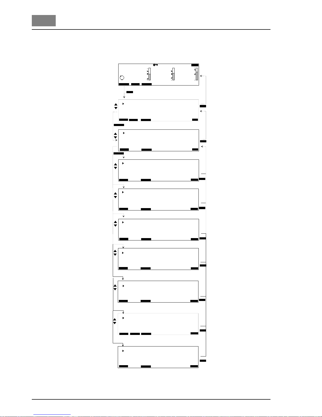
44 WT.050.570.000.DE.IM.0714
Operation DEPOLOX® Pool
1.3
Cl2 settings
(menu 1.1)
Fig. 11 Cl
2
settings
M e n u s e l e c t
A c t u a t o r M e a s . R a n g e
P a r a m e t e r s A d a p t i o n
P a r a m e t e r s E C O S u p e r - C h l o r i n a t i o n
L i m i t v a l u e s
M E N U
C o n t r o l o u t p u t s E l e c t r . P o s . w . Y m
T y 9 0 s
T p 6 0 s
Y m C a l i b r a t i o n A u t o
Y m C a l . 0 %
Y m C a l . 1 0 0 %
M e n u C l 2
C l 2 A c t u a t o r
C l 2 L i m i t V a l u e s
M i n s e t p o i n t 0 . 3 0 m g / l
M a x s e t p o i n t 0 . 6 0 m g / l
M i n 0 , 3 0 m g / l
M a x 0 , 7 5 m g / l
H y s t e r e s i s 0 , 0 5 m g / l
C l 2 M e a s u r i n g R a n g e
R a n g e 0 . . . 3 , 0 0 m g / l
U p o t 2 5 0 m V
µ A r a n g e 1 0 0 µ A
C l 2 A d a p t i o n
T u 0 1 m i n 0 0 s
T s 0 0 h 1 0 m i n 0 0 s
T u E C O 0 1 m i n 0 0 s
T s E C O 0 0 h 1 0 m i n 0 0 s
C i r c u l a t i o n
1 0 0 %
C i r c u l a t i o n E C O 5 0 %
B A C K
E S C
B A C K
E S C
B A C K
E S C
C l 2
p H
R e d o x
C l - N
s e t p o i n t 0 , 5 0 m g / l
X p 1 0 %
T n 2 0 m i n
Y m i n 0 %
Y m a x 1 0 0 %
C l 2 P a r a m e t e r s
B A C K
E S C
m g / l
6 , 8 5
7 0 5
0 , 0 0
1 . 0 0
0 . 4 3
4 . 0 0
9 . 0 0
7 . 0 0
4 0 0
p H
m V
9 0 0
0 , 6 5
1 2 : 3 5
M O D E
C A L
M E N U
P O O L 1
1 0 0 % 2 8 ° C
1
1 . 1
1 . 1 . 1
s e t p o i n t 0 , 3 0 m g / l
X p 1 0 %
T n 2 0 m i n
C i r c u l a t i o n E C O O N 5 0 %
C l 2 P a r a m e t e r s E C O
1 . 1 . 2
1 . 1 . 3
1 . 1 . 4
1 . 1 . 5
1 . 1 . 6
B A C K
E S C
B A C K
E S C
B A C K
E N T E R
B A C K
E N T E R
B A C K
E N T E R
B A C K
E N T E R
B A C K
E N T E R
B A C K
E N T E R
B A C K
E N T E R
B A C K E N T E R
D IID IIID I
II I
L O C K
C o n d u c t i v i t y
S y s t e m
I n p u t s / O u t p u t s
D i a g n o s i s
E N T E R
E N T E R
B A C K
B A C K
A D A P T
C l 2 P e a k c h l o r i n a t i o n
T i m e 1 : 0 0 : 0 0 M o
I n t e r v a l w e e k l y
C l 2 v a l u e 1 . 5 0 m g / l
d u r a t i o n 0 1 : 3 0 h h : m m
m a x . d e l a y
0 4 : 0 0 h h : m m
A l a r m / C l - N D o s O n
1 . 1 . 7
B A C K
E N T E R
B A C K
E S C
Basic display
Menu select
Menu Cl
2
Cl2 actuator
Cl
2
parameters
Cl
2
parameters ECO
Cl
2
limit values
Cl
2
measuring range
Cl
2
adaption
Peak chlorination
Page 45

DEPOLOX® Pool Operation
WT.050.570.000.DE.IM.0714 45
1.3
Cl2 settings
(menu 1.1)
Basic display Refer to main menu
Menu select Display of all available menus
Menu Cl
2
Display of all available Cl2 settings
Cl
2
actuator Control output
Ty 10 s ... 180 s
Tp 010 ... 180 s
Ym Calibration Auto / -
Ym Calibration 0/100 % manual calibration
max. Pulses /min100 / 120
Cl
2
parameters Setpoint 0.10 mg/l ... End of measuring range
Xp 0001 ... 1000 %
Tn 000.0 ... 100.0 min
Ymin, Ymax 000.0 ... 100.0 %
Hysteresis 0.01 ... 0.5 mg/l
min ON for dosing contact 1...59 min.
Cl
2
parameters ECO Setpoint
ECO
0.10 mg/l ... End of measuring range
Xp
ECO
0001 ... 1000 %
Tn
ECO
000.0 ... 100.0 min
Circul.
ECO
ON limit value for switching to ECO mode
for dynamic circulation reduction, 0 ... 100%
Cl
2
limit values Min / Max setpoint min / max setpoint for cedox mode
MIN / Max 0.00 mg/l ... End of measuring range
Hysteresis 0.01 ... 0.25 mg/l or 0.1 ... 2.5 mg/l
Cl
2
measuring range Measuring range0 ... 1 mg/l to 0 ... 20 mg/l
Upot 0 ... 1000 mV (chlorine measuring cell)
µA range 0 µA, 100 µA, 200 µA, 1000 µA
Cl
2
adaption Tu dead time, 1 ... 3600 s
Ts rise time , 0.1 ... 48 0. 0 min
Tu
ECO
during ECO mode, 1 ... 3600 s
Ts
ECO
during ECO mode, 0.1 ... 480.0 min
Circulation
circulation, during which Tu and TS are evaluated
Circul.
ECO
On
circulation, during which Tu
ECO
and TS
ECO
are eval.
ADAPT Start adaption or check last adaption
Cl
2
Peak chlorination Time max. 5 times per week
Interval weekly, every 2, 3, 4 weeks
Cl2 value chlorine value during peak chlorin at ion , 0.. .1 0/ 20 mg /l
Duration duration of the peak chlorination, 0...10 h
Max delay max. time until the peak chlorine value is reached
alarm/Cl-N Dos alarms and Cl-N controller switched on/off
during peak chlorination
Electr.Pos.w.Ym
Dosing pump 2P
Analog output.2P
Electr.Pos.wo.Ym
Pulse pump 2P
Dosing contact for Cl2 dosing with hysteresis and
min swith-on time (e.g. for OSEC-A)
Page 46
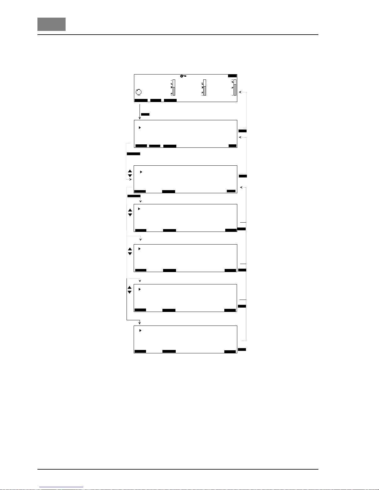
46 WT.050.570.000.DE.IM.0714
Operation DEPOLOX® Pool
1.3
pH settings
(menu 1.2)
Fig. 12 pH settings
A c t u a t o r
P a r a m e t e r s
L i m i t v a l u e s
M e a s u r i n g R a n g e
M e n u p H
B A C K
E S C
B A C K
E S C
B A C K
E S C
M E N U
p H L i m i t V a l u e s
M i n 6 , 5 p H
M a x 7 , 5 p H
H y s t e r e s i s 0 , 2 0 p H
F l o c c . ( m i n ) 6 , 0 0 p H
F l o c c . ( m a x ) 8 , 0 0 p H
p H M e a s u r i n g R a n g e
R a n g e - S t a r t 4 . 0 0 p H
R a n g e - E n d 9 . 0 0 p H
p H A c t u a t o r
C o n t r o l o u t p u t s E l e c t r . P o s . w o . Y m
c o n t r . d i r e c t i o n a c i d
T p 6 0 s
X s h 1 . 0 %
T y 9 0 s
P u l s e s m a x / m i n
1 0 0
m g / l
6 , 8 5
7 0 5
0 , 0 0
1 . 0 0
0 . 4 3
4 . 0 0
9 . 0 0
7 . 0 0
4 0 0
p H
m V
9 0 0
0 , 6 5
1 2 : 3 5
M O D E
C A L
M E N U
P O O L 1
1 0 0 % 2 8 ° C
M e n u s e l e c t
C l 2
p H
R e d o x
C l - N
1
1 . 2
1 . 2 . 1
1 . 2 . 3
1 . 2 . 4
p H P a r a m e t e r s
s e t p o i n t 7 . 0 0 p H
X p 1 0 %
T n 2 0 m i n
Y m i n 0 %
Y m a x 1 0 0 %
1 . 2 . 2
B A C K
E S C
B A C K
E N T E R
B A C K
E N T E R
B A C K
E N T E R
B A C K
E N T E R
B A C K
E N T E R
B A C K
E N T E R
D IID IIID I
II I
L O C K
C o n d u c t i v i t y
S y s t e m
I n p u t s / O u t p u t s
D i a g n o s i s
E N T E R
E N T E R
B A C K
B A C K
Basic display
Menu select
Menu pH
pH actuator
pH parameters
pH limit values
pH measuring range
Page 47

DEPOLOX® Pool Operation
WT.050.570.000.DE.IM.0714 47
1.3
pH settings
(menu 1.2)
Basic display Refer to main menu
Menu select Display of all available menus
Menu pH Display of all available pH settings
pH actuator
Control output
pH settings
Control direct. Acid / alkaline
Tp 10 ... 180 s
Xsh 1.0 ... 5.0 %
Ty 10 ... 180 s
Pulses max./min 100 / 120
pH parameters
Setpoint within measuring range
Xp 0001 ... 1000 %
Tn 000.0 ... 100.0 min
Ymin 000.0 ... 100.0 %
Ymax 000.0 ... 100.0 %
pH limit values
Min within measuring range
Max within measuring range
Hysteresis 0.01 ... 0.25 pH
Flocc. (min) within measuring range*
Flocc. (max) within measuring range *
pH measuring range
Range-start 0.00 ... 5.00 pH
Range-end 9.00 ... 14.00 pH
NOTE
The data is only displayed if the function "ON" has been selected in the
"Inputs/Outputs" menu, "External Functions" (display 1.7.7) under
"Flocculation".
Electr.Pos.wo.Ym
Dosing pump 2P
Dosing pump 3P
Pulse pump 2P
Pulse pump 3P
Analog output.2P
Analog output.3P
*
Page 48
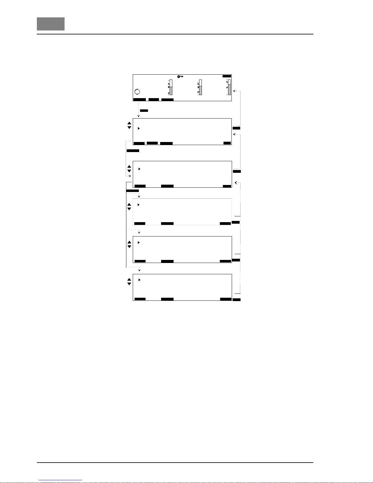
48 WT.050.570.000.DE.IM.0714
Operation DEPOLOX® Pool
1.3
Redox settings
(menu 1.3)
Fig. 13 Redox settings
C E D O X p a r a m e t e r s
L i m i t v a l u e s
M e a s . R a n g e
M e n u R e d o x
R e d o x L i m i t V a l u e s
M i n 6 0 0 m V
M a x 7 5 0 m V
H y s t e r e s i s 2 0 m V
R e d o x M e a s u r i n g R a n g e
R a n g e - S t a r t 4 0 0 m V
R a n g e - E n d 9 0 0 m V
B A C K
E S C
B A C K
E S C
M E N U
m g / l
6 , 8 5
7 0 5
0 , 0 0
1 . 0 0
0 . 4 3
4 . 0 0
9 . 0 0
7 . 0 0
4 0 0
p H
m V
9 0 0
0 , 6 5
1 2 : 3 5
M O D E
C A L
M E N U
P O O L 1
1 0 0 % 2 8 ° C
M e n u S e l e c t
C l 2
p H
R e d o x
C l - N
1
1 . 3
1 . 3 . 2
1 . 3 . 3
B A C K
E N T E R
B A C K
E N T E R
B A C K
E N T E R
B A C K
E N T E R
D I
I
D IIID I
II I
L O C K
C o n d u c t i v i t y
S y s t e m
I n p u t s / O u t p u t s
D i a g n o s i s
E N T E R
E N T E R
B A C K
B A C K
C E D O X P a r a m e t e r s
S e t p o i n t 8 2 0 m V
S e t p o i n t E C O 7 2 0 m V
X s h 0 0 5 m V
m V d e l a y t i m e 1 0 m i n 0 0 s
B A C K
E S C
1 . 3 . 1
B A C K
E N T E R
Basic display
Menu select
Menu Redox
CEDOX Parameters
Redox limit values
Redox measuring range
Page 49

DEPOLOX® Pool Operation
WT.050.570.000.DE.IM.0714 49
1.3
Redox settings
(menu 1.3)
Basic display Refer to main menu
Menu select Display of all available menus
Menu Redox Display of all available Redox settings
CEDOX parameters
setpoint within mV measuring range
setpoint ECO during ECO mode within mV measuring range
Xsh Neutral band for REDOX setpoint, 3 ... 50 mV
mV delay time Reaction time of the REDOX measurement
1...30 min.
Redox limit values
Min within measuring range
Max within measuring range
Hysteresis 001 ... 200 mV
Redox measuring range
Range-start 000 ... 400 mV
Range-end 500 ... 1000 mV
Page 50

50 WT.050.570.000.DE.IM.0714
Operation DEPOLOX® Pool
1.3
Cl-N settings
(menu 1.4)
Fig. 14 Cl-N settings
P a r a m e t e r s
L i m i t v a l u e s
M e a s . R a n g e
M E N U
m a x . c o m b . C l o r 0 , 2 m g / l
m i n . O N 0 0 h 1 5 m i n 0 0 s
m i n . O F F 0 0 h 1 5 m i n 0 0 s
M e n u C l 2 - N
C l - N P a r a m e t e r s
C l - N L i m i t V a l u e s
M i n 0 , 0 0 m g / l
M a x 0 , 2 0 m g / l
H y s t e r e s i s 0 , 0 5 m g / l
C l - N M e a s u r i n g R a n g e
R a n g e 1 , 0 m g / l
D i s p l a y v a l u e C l - N c o m b i n e d
B A C K
E S C
B A C K
E S C
B A C K
E S C
m g / l
6 , 8 5
7 0 5
0 , 0 0
1 . 0 0
0 . 4 3
4 . 0 0
9 . 0 0
7 . 0 0
4 0 0
p H
m V
9 0 0
0 , 6 5
1 2 : 3 5
M O D E
C A L
M E N U
P O O L 1
1 0 0 % 2 8 ° C
M e n u S e l e c t
C l 2
p H
R e d o x
C l - N
1
1 . 4
1 . 4 . 1
1 . 4 . 2
1 . 4 . 3
B A C K
E N T E R
B A C K
E N T E R
B A C K
E N T E R
B A C K
E N T E R
B A C K
E N T E R
D IID IIID I
II I
L O C K
C o n d u c t i v i t y
S y s t e m
I n p u t s / O u t p u t s
D i a g n o s i s
B A C K
B A C K
E N T E R
E N T E R
Basic display
Menu select
Menu Cl-N
Cl-N parameters
Cl-N limit values
Cl-N measuring range
Page 51

DEPOLOX® Pool Operation
WT.050.570.000.DE.IM.0714 51
1.3
Cl-N settings
(menu 1.4)
Basic display Refer to main menu
Menu select Display of all available menus
Menu Cl-N Display of all available total chlorine settings
Cl-N parameters
Max. comb. chlorine within measuring range
min ON 5 ... 120 min
min OFF 5 ... 120 min
Cl-N limit values
Min within measuring range
Max within measuring range
Hysteresis 0.01 ... 0.25 mg/l or
0.1...2.5 mg/l (from measuring range 10.0 mg/l)
Cl-N measuring range Measuring range 0 ... 0.5 mg/l to 0 ... 20 mg/l
Display value Cl-N combined / Cl-N total
Page 52
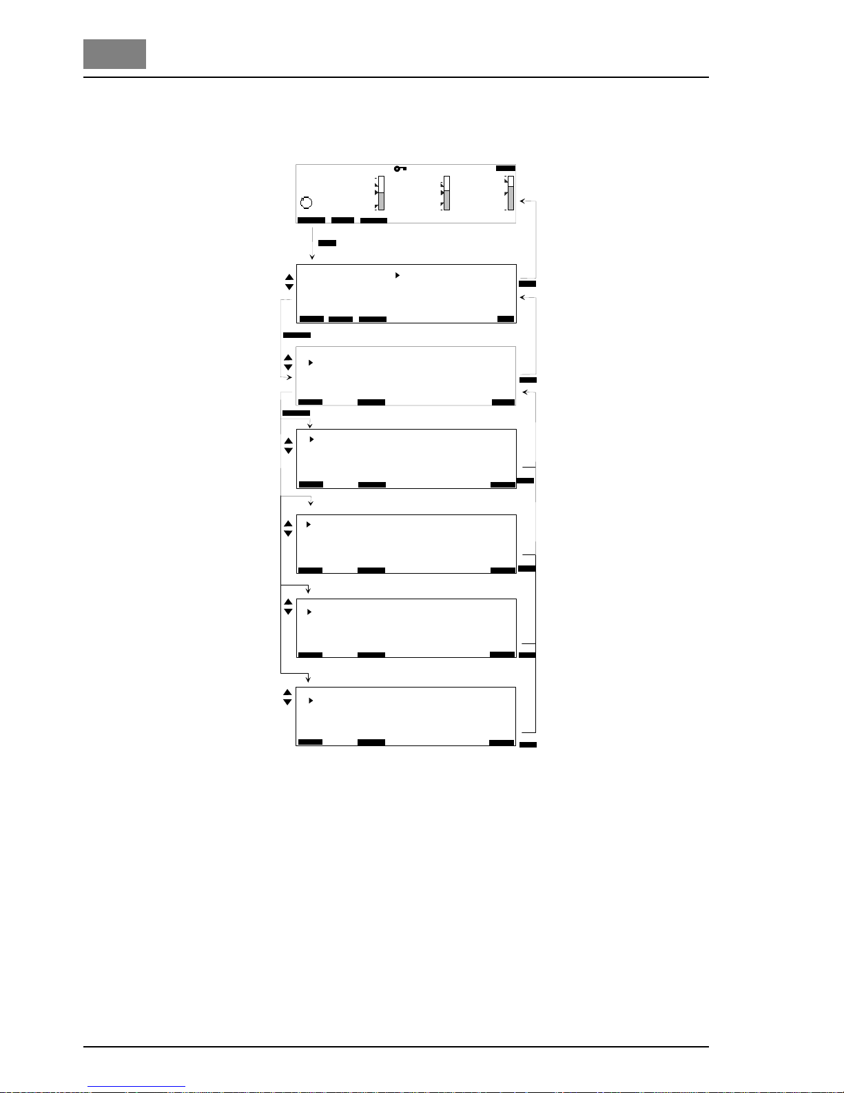
52 WT.050.570.000.DE.IM.0714
Operation DEPOLOX® Pool
1.3
Conductivity settings
(menu 1.5)
Fig. 15 Conductivity settings
A c t u a t o r
P a r a m e t e r s
L i m i t v a l u e s
M e a s . R a n g e
M E N U
M e n u C o n d u c t i v i t y
C o n d u c t i v i t y l i m i t v a l u e s
M i n 2 5 0 µ S / c m
M a x 1 5 0 0 µ S / c m
H y s t e r e s i s 5 µ S / c m
C o n d u c t . M e a s . R a n g e
R a n g e 2 5 0 0 µ S / c m
d i s p l a y N a C l i n g / l
T D S f a c t o r 0 . 7 0
R e f e r . T e m p . 2 5 ° C
B A C K
E S C
B A C K
E S C
m g / l
6 , 8 5
7 0 5
0 , 0 0
1 . 0 0
0 . 4 3
4 . 0 0
9 . 0 0
7 . 0 0
4 0 0
p H m V
9 0 0
0 , 6 5
1 2 : 3 5
M O D E
C A L
M E N U
P O O L 1
1 0 0 % 2 8 ° C
M e n u S e l e c t
C l 2
p H
R e d o x
C l - N
1
C o n d u c t i v i t y A c t u a t o r
C o n t r o l o u t p u t s D o s i n g p u m p 2 p
c o n t r . d i r e c t i o n
d i r e c t
T p 6 0 s
m a x . p u l s e s / m i n 1 0 0
1 . 5 . 1
C o n d u c t i v i t y P a r a m e t e r
s e t p o i n t 7 5 0 µ S / c m
X p 1 0 %
Y m i n 0 %
Y m a x 1 0 0 %
1 . 5 . 2
B A C K
E S C
B A C K
E S C
1 . 5
1 . 5 . 3
1 . 5 . 4
B A C K
E N T E R
B A C K
E N T E R
B A C K
E N T E R
B A C K
E N T E R
B A C K
E N T E R
B A C K
E N T E R
D IID IIID I
II I
L O C K
C o n d u c t i v i t y
S y s t e m
I n p u t s / O u t p u t s
D i a g n o s i s
B A C K
B A C K
E N T E R
E N T E R
Basic display
Menu select
Menu conductivity
Conductivity actuator
Conductivity limit values
Conductivity
measuring range
Conductivity parameters
Page 53

DEPOLOX® Pool Operation
WT.050.570.000.DE.IM.0714 53
1.3
Conductivity settings
(menu 1.5)
Basic display Refer to main menu
Menu select Display of all available menus
Menu conductivity Display of all available conductivity settings
Conductivity actuator
Control output
Control direct. direct/ invers
Pulses max./min 100 / 120
Conductivity parameters
Setpoint within measuring range
Xp 0001 ... 1000 %
Tp 010 ... 180 s
Ymin 000.0 ... 100.0 %
Ymax 000.0 ... 100.0 %
Conductivity limit values
Min within measuring range
Max within measuring range
Hysteresis 0.0 ... 2.5 mS/cm
Conductivity
measuring range
Meas.Range 2500 µS/cm
10.0 / 20.0 / 50.0 / 100.0 / 200.0 mS/cm
display NaCl in g/l /NaCl in % / TDS in g/l / Off
TDS factor whenTDS display is active)
Refer. Temp. Reference temperature
of the displayed conductivity
NaCl in g/l or NaCl in %
Depiction of the sodium chloride content in g/l or in % determined
based on the conductance value of the sample water. In addition to
sodium chloride (salt), water contains other conductive substances as
well, which are also included in the calculation. The zero display only
serves to indicate the determined approximate sodium chloride
content
.
TDS:
TDS = Total Dissolved Solids
The TDS factor depends on the composition of the measured water
and has to be evaluated for each type of water.
Dosing pump 2P
Pulse pump 2P
Analog output.2P
Page 54
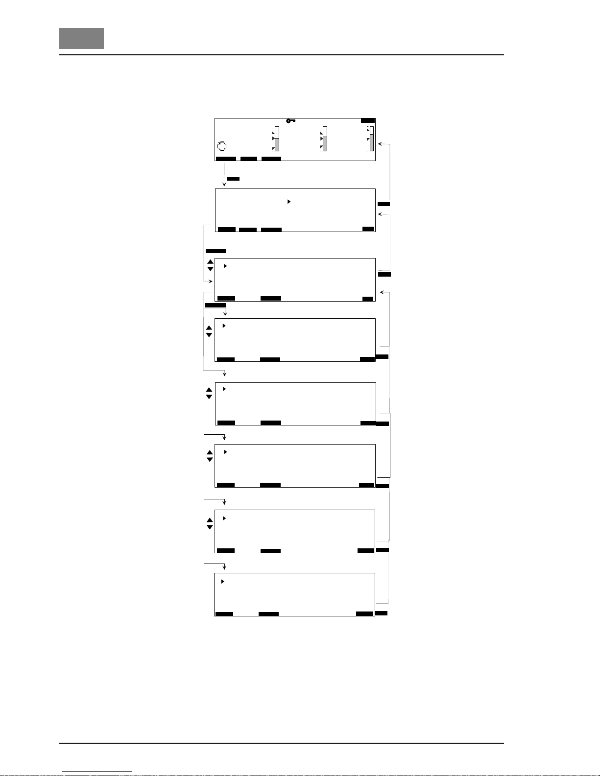
54 WT.050.570.000.DE.IM.0714
Operation DEPOLOX® Pool
1.3
System
(Menu 1.6)
Fig. 16 System settings
C o m m o n
S a f e t y
L i n e d i a g r a m
R e s t a r t
t i m e 0 8 . 4 5
d a t e 2 0 . 1 2 . 0 1
M e a s u r e f i l t e r o f f
H o l d f u n c t i o n o f f
L a n g u a g e E n g l i s h
S y s t e m n a m e P O O L 1
M e n u S y s t e m
C o m m o n
B A C K
E S C
c h a n n e l 1 C l 2
c h a n n e l 2 p H
c h a n n e l 3 m V
c h a n n e l 4 m V
B A C K
E S C
M E N U
S a f e t y
f e e d d e l a y 0 3 m i n 0 0 s
o v e r f e e d d e l a y 0 0 h 0 0 m i n 0 0 s
s a m p . w a t e r d e l a y 0 1 m i n 0 0 s
S y s t e m p a s s w o r d 0 0 0 0
C a l i b r . p a s s w o r d 0 0 0 0
B A C K
E S C
1 . 6
1 . 6 . 1
1 . 6 . 2
1 . 6 . 3
m g / l
6 , 8 5
7 0 5
0 , 0 0
1 . 0 0
0 . 4 3
4 . 0 0
9 . 0 0
7 . 0 0
4 0 0
p H
m V
9 0 0
0 , 6 5
1 2 : 3 5
M O D E
C A L
M E N U
P O O L 1
1 0 0 % 2 8 ° C
M e n u s e l e c t
C l 2
p H
R e d o x
C l 2 - n
1
B A C K
E N T E R
B A C K
E N T E R
B A C K
E N T E R
B A C K
E N T E R
B A C K
E N T E R
D IID IIID I
II I
L O C K
C o n d u c t i v i t y
S y s t e m
I n p u t s / O u t p u t s
D i a g n o s i s
R e s e t
1 . 6 . 4
B A C K
E N T E R
S y s t e m r e s t a r t n o
D e l e t e D i a g r a m n o
F a c t o r y s e t n o
D e l e t e d o s . a v g . n o
B A C K
E S C
B A C K
B A C K
E N T E R
E N T E R
C o n t r o l
C o n t r o l
1 . 6 . 5
B A C K
E N T E R
C o n t r o l m o d e C l 2 s i n g l e F e e d b .
B A C K
E S C
Basic display
Menu select
Menu system
Common
Safety
Line diagram
Reset
System Control
Page 55

DEPOLOX® Pool Operation
WT.050.570.000.DE.IM.0714 55
1.3
System
(Menu 1.6)
Basic display Refer to main menu
Menu select Display of all available menus
Menu system Display of all available system settings
Common
Time (hh:mm) current time
Date (dd.mm.yy) current date
Measure.filter
1)
off / slight / strong
Hold function off / on
(refer to section 1.3.4 Calibration)
Language
System name 12 characters; each with character set
A-Z and digits 1-9 incl. special
characters
Safety
Feed delay
2)
00:00 ... 10:00 min : s
Overfeed delay
3)
00:00:00 ... 10:00:00 h : min : s
Samp.water delay
4)
00:00 ... 10:00 min : s
(sample water delay)
System password four-digit numeric code
(activate with Softkey "LOCK" in the "Menu Select" window)
Calibration password four-digit numeric code
(activate with the "LOCK" softkey in the "Menu Select" window)
Line diagram
Channel 1 to
Channel 4
Reset
System restart
5)
yes / no
Delete diagram
6)
yes / no
Standard values
7)
yes / no
Delete dos.avg
8)
yes / no
Control
control mode
9)
Cl2 single Feedback
CEDOX
Cl2 + ECO CEDOX
NOTE
The system settings marked with 1) to 9) are explained overleaf.
German
English
French
Cl
2
, pH, mV, Cl-N
Conductivity, °C
Ym / Yout Cl
2
Off
Page 56

56 WT.050.570.000.DE.IM.0714
Operation DEPOLOX® Pool
1.3
Explanation of system
settings
1)
Measure.filter The measurement filter serves to compensate measurement value
fluctuations in the event of irregular measurement value signals.
2)
Feed delay The feed delay delays dosing start when the device is switched on and
when the operating mode has been changed. Running of the selected
time can be cancelled with the "Acknowledge" key.
3)
Overfeed delay The maximum dosing time determines how long all control outputs run
at a 100 % dosing capacity in both manual and automatic mode. The
respective controller output is switched off after this time. When the setting is "00:00:00" this function is switched off.
4)
Samp.water delay The sample water delay (DI 1) determines the time after which dosing
is deactivated, e.g. in the event of sample water stop. DI 1 flashes while
the delay time is running.
5)
System restart When the applications are changed the device must be restarted with
System Restart.
6)
Delete diagram The saved values of the past 7 days are deleted.
7)
Standard values Customer settings are deleted (except for the selected application), the
system is reset to the works settings. The sensors must be recalibrated.
8)
Delete dos.avg The average dosing values from display 1.8.3 are reset to zero.
9)
Control modes Refer to chapter 1.2.5
Page 57

DEPOLOX® Pool Operation
WT.050.570.000.DE.IM.0714 57
1.3
Page 58

58 WT.050.570.000.DE.IM.0714
Operation DEPOLOX® Pool
1.3
Inputs/Outputs
(Menu 1.7)
Fig. 17 Input/output settings
m g / l
6 , 8 5
7 0 5
0 , 0 0
1 . 0 0
0 . 4 3
4 . 0 0
9 . 0 0
7 . 0 0
4 0 0
p H
m V
9 0 0
0 , 6 5
1 2 : 3 5
M O D E
C A L
M E N U
P O O L 1
1 0 0 % 2 8 ° C
M e n u S e l e c t
C l 2
p H
R e d o x
C l - N
B A C K
C o n d u c t i v i t y
S y s t e m
I n p u t s / O u t p u t s
D i a g n o s i s
1
M E N U
M e n u I n p u t s / o u t p u t s
A l a r m 1 / 2 f u n c t i o n
A l a r m 3 / 4 f u n c t i o n
A l a r m a s s i g n
A n a l o g o u t
B A C K
1 . 7
E S C
B A C K
E N T E R
E N T E R
D IID IIID I
II I
L O C K
D i g . I n p u t
B A C K
B A C K
E S C
B A C K
E S C
C O N T R O L L E R S T O P
C O N T R O L L E R C O N S T
C H A N G E O V E R M O D E
D I ( 2 )
D I ( 3 )
M A C O N S T A N T
A l a r m 1 f u n c t i o n N O u n l a t c h e d
A l a r m 1 d e l a y 0 0 h 0 0 m i n 6 0 s
A l a r m 2 f u n c t i o n N O u n l a t c h e d
A l a r m 2 d e l a y
0 0 h 0 0 m i n 6 0 s
A l a r m 1 / 2 f u n c t i o n
1 . 7 . 1
1 . 7 . 5
B A C K
E S C
A l a r m 3 f u n c t i o n N O u n l a t c h e d
A l a r m 3 d e l a y 0 0 h 0 0 m i n 6 0 s
A l a r m 4 f u n c t i o n N O u n l a t c h e d
A l a r m 4 d e l a y
0 0 h 0 0 m i n 6 0 s
A l a r m 3 / 4 f u n c t i o n
1 . 7 . 2
A l a r m a s s i g n
A l a r m 1
A l a r m 2
A l a r m 3
A l a r m 4
C l 2
L O
H I
P H
M V
C l - N
S A M P L E W ( 1 )
D I ( 2 )
D I ( 3 )
1 . 7 . 3
B A C K
E N T E R
B A C K
E N T E R
B A C K
E N T E R
B A C K
E N T E R
E R R O R
C H A N G E
S E L E C T
E C O N O M I C
I n t e r f a c e
R S 2 3 2 P r i n t e r
R S 4 8 5 a d d r e s s 0 0
C A N S e g m e n t 0 1
B A C K
E S C
1 . 7 . 6
B A C K
E N T E R
D i g i t a l I n p u t
I n t e r f a c e
E x t e r n a l F u n c t i o n s
B A C K
E S C
A n a l o g o u t
1 . 7 . 4
B A C K
E N T E R
m A 1 C l 2
m A 2 p H
m A 3 m V
m A 4 m V
m A s i g n a l 0 . . . 2 0 m A
E N T E R
E N T E R
B A C K
C O N D U C .
Basic display
Menu select
Menu
Inputs / Outputs
Alarm 1/2 function
Alarm 3/4 function
Alarm assign
Analog out
Digital input
Interface
Page 59
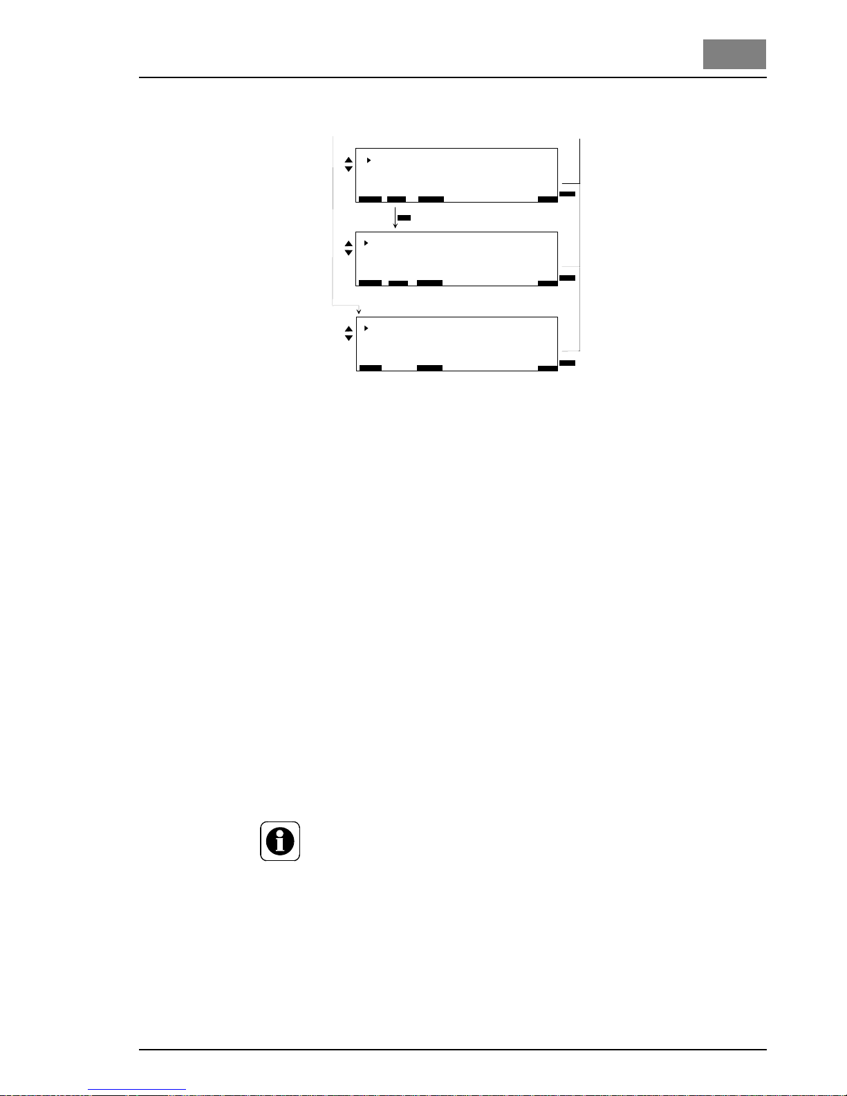
DEPOLOX® Pool Operation
WT.050.570.000.DE.IM.0714 59
1.3
Fig. 17 continued
Inputs/Outputs
(Menu 1.7)
Basic display Refer to main menu
Menu select Display of all available menus
Menu
Inputs / Outputs
Display of all available input/output settings
Alarm 1/2 function
Alarm 1 function refer to section 2.6.2, alarms
Alarm 1 delay 00:00:00 ... 10:00:00 h : min : s
applies in the same manner for Alarm 2
Alarm 3/4 function
As for Alarm 1/2
Alarm assign
Alarm 1 ... 4 Each alarm contact can be assigned
several alarm conditions with the
"SELECT" softkey.
If several alarm conditions have been selected, the alarm is activated
each time a new alarm condition occurs.
NOTE
Alarm 1: Function/assignment only with DIN function set to "Off"
(Display 1.7.7)
Alarm 2: Function/assignment only with flocculation set to "Off"
(Display 1.7.7)
Alarm 3: Only with application 1, 3 and 4
Alarm 4: Only with application 1 and 4
E x t e r n a l F u n c t i o n s
E S C
B A C K
1 . 7 . 7
B A C K
F l o c c u l a t i o n O f f
D I N 1 9 6 4 3 f u n c t O f f
D y n . E C O s i g n a l 0 . . . 2 0 m A
E N T E R
E S C
B A C K
1 . 7 . 7
B A C K
E N T E R
L i m i t v a l u e s D I N
C l 2 M i n 0 . 3 0 m g / l
C l 2 M a x 0 . 6 0 m g / l
p H M i n 6 . 5 0 p H
p H M a x 7 . 6 0 p H
R e d o x M i n 7 5 0 m V
C l - N M a x 0 . 2 0 m g /
l
E S C
B A C K
1 . 7 . 8
B A C K
E N T E R
F l o c c u l a t i o n P a r a m e t e r
V o l u m e f l o w 8 0 m3/ h
P u m p 5 0 m l / h
F l o c c . d o s a g e 0 , 5 g / h
F l o c c c t r l . 1 0 0 % 4 3 %
F l o c c c t r l . E C O 1 1 %
- - >
- - >
- - >
Flocculation parameter
External functions
Page 60

60 WT.050.570.000.DE.IM.0714
Operation DEPOLOX® Pool
1.3
Analog out mA 1 ... 4
mA signal 0 ... 20 mA / 4 ... 20 mA
NOTE
mA 1: Not available when Cl
2
control output set to "analog output"
(Display 1.1.1)
mA 2: Not available when pH control output on "analog output"
(Display 1.2.1)
mA 3: Not available when conductivity control output on "analog
output"
(Display 1.5.1)
Digital input
DI (2) / DI (3) Each digital output can be assigned a
parameter with the softkey "SELECT"
CONTROLLER STOP Yout = 0 %, positioner closed, pumps off,
mA analog output = 0 %
CONTROLLER CONST Yout remains constant, i.e. the control
signals are kept constant
MA CONSTANT All mA outputs remain unchanged.
CHANGEOVER MODE When DI is activated, changeover from
Automatic to Manual, positioner constant,
pump off, mA analog output= 0 %
ECONOMIC When DI is activated, the ECO
parameters are used for chlorine and
flocculation
control
Interface
RS232
RS485 address Bus addresses 00 ... 31
CAN segment Segment address of the CAN bus, 0...63
External functions
(Release external
control functions)
Flocculation Off / On
DIN 19643 funct. Release contact when DIN values
are met, e.g. for decreasing circulation
Off / On)
Cl
2
pH
mV
Cl-N
Conductivity
°C
Ym / Yout Cl
2
Off
Printer
IAP-Download
Off
Page 61

DEPOLOX® Pool Operation
WT.050.570.000.DE.IM.0714 61
1.3
Flocculation parameter
(when flocculation "ON")
Circulation 010 ... 1000 m
3
/h
Pump 0010 ... 1,000 ml/h
Concent. flocc. 0.1 ... 2.0 g/m
3
Flocc.ctrl 100 % 000 ... 100 %
Flocc.ctrl ECO 000 ... 100 %
Limit values DIN This menu is accessible with the softkey "- - >" in the menu "External
Functions", when the DIN function is activated.
Cl2 Min within the measuring range
Cl2 Max within the measuring range
pH Min within the measuring range
pH Max within the measuring range
Redox Min within the measuring range
Cl-N Mac within the measuring range
Page 62
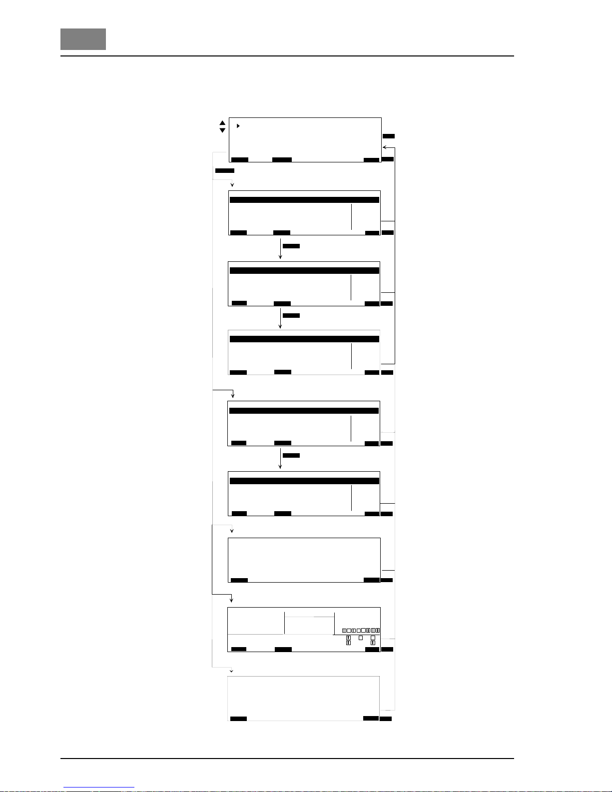
62 WT.050.570.000.DE.IM.0714
Operation DEPOLOX® Pool
1.3
Diagnosis
(Menu 1.8)
Fig. 18 Diagnosis settings
1 . 1 1 . 0 5 . 0 4 1 0 : 4 5 0 . 0 2 µ A 3 . 8 µ A / m g / l 1 1 , 3 µ A
B A C K
1 . 8 . 1
D i a g n o s i s
C l 2 / p H / O R P
C l - N / C o n d .
D o s i n g a v e r a g e
I n p u t s / O u t p u t s
1 . 8
D i a g n o s i s C l 2
D i a g n o s i s p H
1
2
D I
3
R S 4 8 5 R X D
R S 2 3 2 T X D
B A C K
D i a g n o s i s I n p u t s / O u t p u t s
1 . 8 . 1
1 . 8 . 4
B A C K
E S C
B A C K
E S C
B A C K
E S C
B A C K
E S C
B A C K
E N T E R
B A C K
B A C K
E S C
D i a g n o s i s S o f t w a r e v e r s i o n s
1 . 8 . 5
B A C K
1 D E S C h l o r
2 m V I n p u t 1 . 0 3
3 m V I n p u t 1 . 0 3
4
5
6 m A o u t 4 x 1 . 0 1
M a i n C P U
0 2 . 1 0 E A E 1 0 2 2
D i s p l a y V e r s i o n
0 1 . 0 2 E A E 1 0 1 7 0 1
D I N
m A 1 : c o n t r . C l 2 7 m A / 3 5 %
m A 2 : p H 2 m A / 1 0 %
m A 3 : m V 4 m A / 2 0 %
m A 4 : - -
Y o u t :
A p p l . 1
B A C K
E S C
D i a g n o s i s D o s i n g a v e r a g e
1 . 8 . 3
B A C K
C l 2 0 . 0 % / h o u r
p H 0 . 0 %
C o n d u c t i v i t y 0 . 0 %
F l o c c u l a t i o n 0 . 0 %
B A C K
E N T E R
B A C K
1 . 8 . 1
D i a g n o s i s O R P
1 . 8 . 2
B A C K
E S C
B A C K
E S C
B A C K
D a t e t i m e z e r o D P D - m g / l a c t . ( I )
2 . 1 8 . 0 3 . 0 4 1 3 : 0 5 0 . 0 2 µ A 3 . 9 µ A / m g / l
1 . 1 1 . 0 5 . 0 4 1 0 : 4 5 0 , 5 m V 5 8 . 5 m V + 0 . 0 0 p H - 2 3 , 3 m V
D a t e t i m e p H 7 s p a n / p H o f f s a c t . ( U )
2 . 1 8 . 0 3 . 0 4 1 3 : 0 5 1 . 8 m V 5 7 , 6 m V
D a t e t i m e o f f s e t a c t . ( U )
1 . 1 1 . 0 5 . 0 4 1 0 : 4 5 1 3 . 6 m V + 7 5 3 , 3 m V
2 . 1 8 . 0 3 . 0 4 1 3 : 0 5 1 0 . 9 m V
1 . 1 1 . 0 5 . 0 4 1 0 : 4 5 8 . 5 µ A / m g / l + 2 , 3 µ A
D a t e t i m e s p a n a c t . ( I )
2 . 1 8 . 0 3 . 0 4 1 3 : 0 5 5 , 6 µ A / m g / l
D i a g n o s i s C l - N
B A C K
1 . 8 . 2
1 . 1 1 . 0 5 . 0 4 1 0 : 4 5 1 . 0 + 2 , 3 µ A
D a t e t i m e s p a n a c t . ( I )
2 . 1 8 . 0 3 . 0 4 1 3 : 0 5 1 . 1 + 3 5 . 0 m V
D i a g n o s i s C o n d u c t i v i t y
C l 2 : 1 0 0 . 0 %
p H : 2 5 . 3 %
C o n : 1 0 . 7 %
C E D O X t i m e
2 . 0 2 0 0 : 0 0 : 0 0
1 32 4 5 6 7 8
K
C A N T R
F l o c .
- - >
- - >
- - >
- - >
- - >
- - >
- - >
- - >
B A C K
E S C
- - >
S o f t w a r e v e r s i o n s
Menu Diagnosis Cl2
Menu Diagnosis pH
Diagnosis ORP
Diagnosis Cl-N
Diagnosis Conductivity
Dosing average
Software version
Basic display and Menu
select are not shown
Diagn.
Inputs/Outputs
Page 63

DEPOLOX® Pool Operation
WT.050.570.000.DE.IM.0714 63
1.3
Diagnosis
(Menu 1.8)
Basic display Refer to main menu
Menu select Display of all available menus
Menu diagnosis Display of all available diagnosis displays
Diagnosis
(Cl
2
; pH; Redox;
Cl-N; Cond.)
Information on the existing measurement inputs
Date and time of the last 5 calibrations
zero zero at calibration
pH7 calibration offset at pH7
DPD mg/l DPD at calibration
Span/pH Signal span at pH calibration
Offs. Signal offset at pH and mV calibation
act. present sensor signal
Span Signal span at conductivity
Dosing average Display of the average dosing rates in % during the set period:
hour last hour
day last day
week last week
month last month
Diagn.
Inputs/Outputs
Information on
the assignment of the mA outputs
the current mA output in mA and %
present dosing output Yout for Cl2, pH, conductivity in %
CEDOX: Present calculated contamination of the pool water
Remaining mV delay time until the CEDOX factor is checked again.
The current switching conditions of the relays
Relay off
Relay on
The selected application
The send/receive condition of both interfaces RS485 and RS232
The current switching conditions of the digital inputs
Flocculation, DIN function On/Off
Software version Information on the software versions
The sensor measuring modules in the slots 1 to 5
The analog outputs card
The main CPU
The graphic display
Page 64
64 WT.050.570.000.DE.IM.0714
Operation DEPOLOX® Pool
1.3
1.3.4 Calibration
Temperature
calibration
1. Starting from the basic display in the main menu select the "Calib-
ration" area of operation.
2. Select the "Temperature" menu item
"Calibr.Temperatur" (Display 2.1.6) appears on the graphic display.
3. Select the "Cal. °C" parameter.
4. Perform comparative temperature measurement.
5. Use the arrow keys to enter the value to be calibrated.
6. Confirm the entry.
Temperature calibration is then concluded.
Sensor measuring
module calibration
CAUTION!
With the pressurised version, when calibrating the sensor measu-
ring modules
pH value
Redox potential
Conductivity
you must also perform the following:
Before calibration:
1. Close the ball valves on the inlet and outlet.
2. Depressurise the unit. To this purpose open and close the
knurled nut on the drain briefly.
After calibration:
Open the inlet and outlet.
The electrode fingers or membranes on the sensors are extremely sensitive! Do not touch, soil or damage.
WARNING!
Some of the buffer solutions are caustic and can cause burns.
Avoid contact with the eyes or the skin.
NOTE
To prevent the output of non-permissible control sig nals during cali-
bration, the "Hold function" in the system menu (display 1.6.1)
should be set to "On" (mA-outputs and controller outputs then remain constant during calibration).
The lower clip must be fitted into the top mount if the supplied bea-
ker is to be used, if a bag with calibration solution is used it must be
fitted into the bottom mount.
Concerning the frequence of calibration refer to the corresponding
standards (e.g. DIN 19643). Refer to the recommended intervals in
the maintenance chapter.
Page 65

DEPOLOX® Pool Operation
WT.050.570.000.DE.IM.0714 65
1.3
The test configuration for the sensors which are calibrated outside the
cell body is shown in Fig. 19 as an example.
Fig. 19 Test configuration (example)
1 Ball valve on sample water inlet
(on the pressurised version also on the sample water drain)
2 Lower clip
3 Beaker
4 Sensor
5 Top clip with electrode mount
Chlorine calibration During chlorine calibration each chlorine sensor (free chorine or total
chlorine) must be calibrated separately.
Free chlorine
(Cl
2
)
During calibration for free chlorine a zero point calibration and a
measurement value calibration (DPD1) must be performed.
Zero point calibration 1. Starting from the basic display in the main menu select the "Calib-
ration" area of operation.
2. Select the menu item "Cl
2
".
The window "Calibration Cl
2
" (display 2.1.1) appears on the graphic
display.
3. Select the parameter "Cal.zero point" and confirm the selection.
4. Close the ball valve on the sample water inlet.
NOTE
When the sample water supply has been stopped, the display first
drops rapidly, and after approximately one minute only slowly towards
zero. During commissioning it is essential to wait for 5 minutes, even if
the display should show "0.00" or flash after a few seconds.
5. Wait until the displayed chlorine value no longer changes.
6. Press the "ENTER" softkey to set the display to "0.00".
7. Open the ball valve on the sample water inlet.
1
2
3
4
5
Page 66
66 WT.050.570.000.DE.IM.0714
Operation DEPOLOX® Pool
1.3
Measurement value
calibration (DPD)
8. After zero point calibration wait at least 2 minutes.
9. Open the knurled nut on the drain by approximately one turn and
extract a specimen of the sample water.
10. Determine the free chlorine content of the specimen with a photometer.
11. Select the parameter "Cal. DPD" and confirm the selection.
12. Use the arrow keys to enter the determined value.
13. Confirm the entry.
Calibration for free chlorine is then concluded.
NOTE
During calibration for total chlorine or combined chlorine only one calibration must be performed.
Total chlorine 1. Open the knurled nut on the drain by approximately one turn and
extract a specimen of the sample water.
2. With a comparative device determine the total chlorine content
(DPD3).
3. Starting from the basic display in the main menu select the "Calibration" area of operation.
4. Select the menu item "Cl-N".
The window "Calibration Cl-N" (display 2.1.4) appears on the
graphic display.
NOTE
If the DEPOLOX
®
Pool is not fitted with a free chlorine measurement
system, it is necessary to measure the free chlorine using a photometer
and enter the value in the "Enter free Cl
2
" menu before performing total
chlorine calibration.
5. Select the parameter "Cal. total" and confirm the selection.
6. Use the arrow keys to enter the determined value.
7. Confirm the entry.
Calibration for total chlorine is then concluded.
Combined chlorine 1. Determine the values for free chlorine (DPD1) and total chlorine
(DPD3) as described under "Total chlorine".
2. Determine the value for combined chlorine:
Total chlorine DPD3 minus free chlorine DPD1.
3. Enter the determined value as described under "Total chlorine"
with the arrow keys under the parameter "Cal. combined".
4. Confirm the entry.
Calibration for combined chlorine is then concluded.
Page 67

DEPOLOX® Pool Operation
WT.050.570.000.DE.IM.0714 67
1.3
pH calibration
NOTE
During pH calibration the buffer solution and the sample water
should have the same temperature. If there is a difference in temperature of > 5 °C first enter the temperature of the buffer solution
in the "Calibration" menu under "Calibration pH" (Display 2.1.2) for
the parameter "Cal. at temp".
pH-7 alignment 1. Starting from the basic display in the main menu select the "Calib-
ration" area of operation.
2. Select the "pH" menu item.
The window "Calibr. pH" (Display 2.1.2) appears on the graphic
display.
3. Select the "Cal. pH7" parameter.
4. Place one of the supplied beakers into the bottom clip and fill with
the buffer solution "pH 7.00" or a bag with buffer solution "pH 7.00"
into the bottom clip.
5. Pull or unscrew the pH sensor from the lid of the cell body.
6. Dip the pH sensor through the top clip at least 2 cm deep into the
buffer solution and move slightly until the indicated pH value remains constant.
7. Use the four arrow keys to enter the value to be calibrated.
8. Confirm the entry.
Slope alignment 9. Remove the buffer solution "pH 7.00" from the bottom clip.
10. Wash the sensor in distilled water to prevent carry-over of the buffer solution.
11. Select the parameter "Cal. pH" and confirm the selection.
12. Place one of the supplied beakers into the bottom clip and fill with
the buffer solution "pH 4.65" or clamp a bag with buffer solution "pH
4.65" into the bottom clip.
NOTE
?
If buffer solutions other than those stated are used, the pH value of
the buffer solution must be lower than pH 6 or higher than pH 8.
13. Dip the pH sensor at least 2 cm deep into the buffer solution and
move slightly until the indicated pH value remains constant.
14. Use the four arrow keys to enter the value to be calibrated.
15. Confirm the entry.
16. Remove the pH sensor from the top clip.
17. Insert or screw the pH sensor into the lid of the cell body.
The pH measurement is then calibrated.
Page 68
68 WT.050.570.000.DE.IM.0714
Operation DEPOLOX® Pool
1.3
Offset alignment If external influences result in a constant difference between the dis-
played pH value and a pH value measured manually, this difference
can be compensated:
1. Starting from the basic display in the main menu select the "Calibration" area of operation.
2. Select the "pH" menu item.
3. Select the "Offset pH" parameter.
4. With the four arrow keys enter the difference between the comparative value and the displayed value (comparative value minus the
displayed value).
5. Confirm the entry.
The pH offset is then concluded.
NOTE
The offset is deleted each time a new pH-7 alignment or slope alignment is performed.
Redox
calibration (mV)
NOTE
Redox sensors have long running-in times. After calibration with a buffer solution it can therefore take several hours until the value has stabilised.
1. Starting from the basic display in the main menu select the "Calibration" area of operation.
2. Select the "Redox" menu item
The window "Calibration ORP" (Display 2.1.2) appears on the graphic
display.
Select the "Cal. mV" parameter.
3. Place one of the supplied beakers into the bottom clip and fill with
the buffer solution "478 mV" or clamp a bag with buffer solution
"478 mV" into the bottom clip.
4. Pull or unscrew the Redox sensor from the lid of the cell body.
5. Dip the Redox sensor through the top clip at least 2 cm deep into
the buffer solution and move slightly until the indicated value remains constant.
6. Use the arrow keys to enter the value to be calibrated.
7. Confirm the entry.
8. Remove the Redox sensor from the top clip.
9. Insert or screw the Redox sensor into the lid of the cell body.
Redox calibration is then concluded.
Page 69

DEPOLOX® Pool Operation
WT.050.570.000.DE.IM.0714 69
1.3
Conductivity
calibration
NOTE
The conductivity sensor has an integrated temperature sensor and
therefore an automatic temperature compensation feature.
In the "Calibr.Conductivity" window (Display 2.1.5) the temperature of
the temperature sensor in the conductivity sensor can be adapted with
the parameter "Cal. °C" to a comparative measurement.
1. Starting from the basic display in the main menu select the "Calibration" area of operation.
2. Select the "Conductivity" menu item.
The window "Calibr.Conductivity" (Display 2.1.5) appears on the
graphic display.
3. Select the "Cal. mS/cm" parameter.
4. Place one of the supplied beakers into the bottom clip and fill with
the buffer solution "60.0mS/cm" or clamp a bag with buffer solution
"60.0 mS/cm" into the bottom clip.
5. Pull or unscrew the conductivity sensor from the lid of the cell body.
6. Dip the conductivity sensor through the top clip at least 4 cm deep
into the calibration solution.
7. Pull out the conductivity sensor and rinse off with distilled water.
8. Repeat the dipping and rinsing procedure several times.
9. Replace the calibration solution in the bottom clip with a new solution.
10. Repeat measurement. Move the conductivity sensor slightly until
the displayed value remains constant.
11. Use the arrow keys to enter the value to be calibrated.
12. Confirm the entry.
13. Insert or screw the conductivity sensor into the lid of the cell body.
Conductivity calibration is then concluded.
Page 70

70 WT.050.570.000.DE.IM.0714
Operation DEPOLOX® Pool
1.3
1.3.5 Setting Overview - Specifications
DEPOLOX-POOL Works setting Commissioning
Cl
2
actuator
Control output Electr.Pos.w.Ym
Ty 80 s
Tp 60 s
Pulses max./min. 100
Cl
2
parameters
Setpoint 0.45 mg/l
Xp 100 %
Tn 20.0 min
Ymin 0.0 %
Ymax 100.0
Hysteresis 0.05 mg/l
min ON 10 min.
Cl
2
parameters ECO
Setpoint
ECO
0.45 mg/l
Xp
ECO
100 %
Tn
ECO
20.0 min
Circulation ECO ON 50%
Cl
2
limit values
Min setpoint 0.30 mg/l
Max setpoint 0.80 mg/l
Min 0.30 mg/l
Max 0.60 mg/l
Hysteresis 0.05 mg/l
Cl
2
measuring range
Measuring range 1.0 mg/l
Upot 250 mV
µA measuring range 100 µA
Cl
2
adaption
Tu 01min 00s
Ts 00h 10 min 00s
Tu
ECO
01min 00s
Ts
ECO
00h 10min 00s
Peak chlorination
Time --Interval weekly
Chlorine value 1.50 mg/l
Duration 01h 00min 00s
max. delay 00h 40min 00s
Alarm/Cl-N Dos. On
Page 71
DEPOLOX® Pool Operation
WT.050.570.000.DE.IM.0714 71
1.3
pH actuator
Control output Dosing pump 2P
Control direct. Acid
Tp 60 s
Xsh 1 %
Ty 90 s
Pulses max./min. 100
pH parameters
Setpoint 7.00 pH
Xp 10 %
Tn 0.0 min
Ymin 0.0 %
Ymax 100.0
pH limit Values
Min 6.50 pH
Max 7.60 pH
Hysteresis 0.05 pH
Flocc. (min) 6.00 pH
Flocc. (max) 8.00 pH
pH measuring range
Range-start 4.00 pH
Range-end 9.00 pH
CEDOX parameters
Setpoint 760 mV
Setpoint
ECO
650 mV
Xsh 005 mV
mV delay time 10min 00s
Redox limit values
Min 600 mV
Max 750 mV
Hysteresis 5 mV
Redox measuring range
Range-start 400 mV
Range-end 900 mV
Cl-N parameters
Max. comb. chlor 0.20 mg/l
min ON 00h 15min 00s
min OFF 00h 15min 00s
Cl-N limit values
Min 0.00 mg/l
Max 0.20 mg/l
Hysteresis 0.05 mg/l
Page 72
72 WT.050.570.000.DE.IM.0714
Operation DEPOLOX® Pool
1.3
Cl-N measuring range
Measuring range 1.00 mg/l
Display value Cl-N combined
Conductivity actuator
Control output Dosing pump 2P
Control direct. direct
Tp 60 s
Pulses max./min. 100
Conductivity
parameters
Setpoint 750 µS/cm
Xp 10 %
Ymin 0.0 %
Ymax 100.0
Conductivity limit
values
Min 250 µS/cm
Max 1500 µS/cm
Hysteresis 5 µS/cm
Conductivity measuring
range
Measuring range 2500 µS/cm
Display NaCl in g/l
TDS factor 0.70
Reference temperature 25°C
Common
Measure.filter Off
Hold function Off
Language German
System name POOL 1
Safety
Feed delay 03min 00s
Overfeed delay 00 h 00 m i n 00 s
Samp.water delay 01min 00s
System password 0000
Calibr.password 0000
Line diagram
Channel 1 Cl
2
Channel 2 pH
Channel 3 mV
Channel 4 °C
Control
Control mode Cl
2
single feedb.
Page 73

DEPOLOX® Pool Operation
WT.050.570.000.DE.IM.0714 73
1.3
Alarm 1/2 function
Alarm 1 function N.O.unlatched
Alarm 1 delay 00h 00min 00s
Alarm 2 function N.O.unlatched
Alarm 2 delay 00h 00min 00s
Alarm 3/4 function
Alarm 3 function N.O.unlatched
Alarm 3 delay 00h 00min 00s
Alarm 4 function N.O.unlatched
Alarm 4 delay 00h 00min 00s
Alarm assign
Alarm 1
Alarm 2
Alarm 3
Alarm 4
Analog out
mA1 Off
mA2 Off
mA3 Off
mA4 Off
mA-signal 4...20 mA
Digital input
DI (2) CONTROLLER STOP
DI (3) ECONOMIC
Interface
RS232 Off
RS485 address 00
CAN segment 01
External functions
Flocculation Off
DIN 19643 funct. Off
Limit values DIN
Cl2-Min 0.30 mg/l
Cl2-Max 0.60 mg/l
pH-Max 7.60 pH
pH-Min 6.50 pH
Redox-Min 750 mV
Cl-N-Max 0.20 mg/l
Page 74

Operation DEPOLOX® Pool
74 WT.050.570.000.DE.IM.0714
Flocculation parameter
Circulation 100 m³/h
Pump 50 ml/h
Flocc.dosage 0.5 g/m³
Flocc.ctrl 100% 100 %
Flocc.ctrl ECO 50 %
Page 75
DEPOLOX® Pool Errors
WT.050.570.000.DE.IM.0714 75
1.4
1.4 Errors
Error messages The following table shows and explains all possible error messages
which can be displayed. If several errors occur at the same time, the
corresponding messages appear alternately in succession. When the
error has been remedied, the error message is automatically deleted.
If you are unable to remedy the error yourself, please contact your contractual partner.
Error message Cause Remedy
Measured value display flashes
Measured value outside the measuring range
Select different range
Check calibration
Positioner feedback
signal flashes
Positioner is in manual mode Press the hand knob of the position-
er
NO SIGNAL
Cable between display and mainboardnot correctly plugged or defective or mainboard defective
Check the cable, replace if necessary. Replace the mainboard
(Evoqua service personnel)
DI I flashes Sample water flow recently insuffi-
cient (delay running)
Check the sample water flow
(approx. 33 l/h)
DI I Permanent display
Sample water flow insufficient for some time (delay elapsed)
Clean or replace the filter
Multi-sensor incorrectly connected
or defective
DI II and DI III Signal on signal input DI II or DI III Check connection and setting
Zero Cl2 ? Bad connection on sensor cable Check cable
Max. zero point compensation exceeded, Cl
2
sensor defective
Check zero point sensor current
(-5 ... +5 µA)
If necessary replace Cl
2
sensor
DPD Cl2? Slope error
The value of the minimum current
difference required for slope alignment for the full measuring range
has dropped below the minimum value.
Range: Minimum current difference
70 µA 0.2 µA/mg/l
100 µA 0.4 µA/mg/l
200 µA 2.0 µA/mg/l
1000 µA 4.0 µA/mg/l
Check the Cl
2
sensor
Clean the electrodes
Check the pH value of the water
(< pH 8)
Organic chlorine compound (e. g.
chlorine stabiliser chlorisocyanurate) in the water
Do not add any chlorine stabilisers to
the water
Upot for Cl
2
sensor incorrect Adjust the Upot: 250 mV
Page 76

76 WT.050.570.000.DE.IM.0714
Errors DEPOLOX® Pool
1.4
Calib pH? The tolerance of ± 100 mV during
pH-7 calibration was exceeded.
During slope alignment the range of
49...70 mV/pH value was exceededwas exceeded.
Check the electrode, cable and buffer solution
Use fresh buffer solution
Check the values in the diagnosis
menu
Replace pH-electrode if necessary
If an impedance converter is used:
Replace battery
Calib ORP? The tolerance of ± 50 mV during
calibration with buffer solution 478
mV was exceeded.
Check the electrode, cable and buffer solution
Use fresh buffer solution
Check the values in the diagnosis
menu
Replace Redox-electrode if
necessary
If an impedance converter is used:
Replace battery
Calib Cond.? The slope tolerance value was eit her
insufficient or exceeded.
Use fresh buffer solution
Calib Cl-N ? Slope error
The minimum slope value required
for slope alignment
(1.0 µA/mg/l Cl
2
) was not met.
Perform sensor maintenance
(refer to separate operating instructions for the sensor)
Page 77
DEPOLOX® Pool Errors
WT.050.570.000.DE.IM.0714 77
1.4
Error message Cause Remedy
mA output 1?
mA output 2?
mA output 3?
mA output 4?
Load error
The mA output cannot drive its mA
output current through the connected current loop (400 Ohm at 20 mA
max.).
Check whether the mA signal is re-
quired at all (e.g. for plotter). If not, in
the "INPUTS/OUTPUTS" menu,
analog output, switch off the output
signal.
Check the mA signal cable for inter-
ruption
Resistance in the current loop
> 400 Ohm (bridge: L)
> 1000 Ohm (bridge: H)
Reset the respective bridge on the
plug-in module "mA outputs":
L: < 400 Ohm
H: < 1000 Ohm
Temperature Interruption or short-circuit in the
temperature sensor or cable
Check the multi-sensor and cable
Setpoint Cl2?
Setpoint pH?
Setpoint Cond?
Setpoint Cl-N?
Setpoint error
Due to modification of the measuring
range the setpoint of the controller is
outside the measuring range.
Reset the controller setpoint or ad-
just the measuring range.
Limit Cl2?
Limit pH?
Limit ORP?
Limit Cond?
Limit Cl-N?
Limit value error
Due to modification of the measuring
range the limit value is outside the
measuring range.
Reset the limit value or adjust the
measuring range.
Cell Cl2 ?
Cell pH?
Cell ORP?
Cell Cond?
Cell Cl-N?
Chlorine sensor not correctly fitted.
Sand cleaning not effective.
Sensor, sensor cable or se nsor module defective.
µA-range of the sensor measuring
module exceeded (e.g. during peak
chlorination).
Correctly screw-in the chlorine sen-
sor. Check the sand cleaning.
Check the sensor, sensor cable or
sensor module, replace if necessary .
Peak chlorination stopped. Set lower
peak chlorination setpoint.
Set the µA measuring range
(menu 1.1.5)
70 µA
100 µA
200 µA
1000 µA
mA-OUT 1
mA-OUT 2
mA-OUT 3
mA-OUT 4
W&T00056
Page 78
78 WT.050.570.000.DE.IM.0714
Errors DEPOLOX® Pool
1.4
Error message Cause Remedy
Positioner Ym ? Ym range too narrow
Position 0 % or 100 % incorrectly calibrated
Set gap between 0 % and 100 % to
at least 50 % of the entire path
Positioner selected, but not connected
Check setting: Positioner with Ym
Feedback signal incorrect Check feedback (1 kOhm)
Positioner feedback incorrectly con-
nected or defective
Check ( refer to terminal diagrams)
Module ? Sensor module has been removed
Sensor module defective
Refit or replace the sensor module
Adaption ? Adaption terminated with error Refer to adaption
Overfeed ? Set maximum dosing time of a con-
trol output exceeded
Check cause, e. g. chemical tank
empty, check the dosing pump
DIN 19643 funct.? At least one of the values Cl
2
, pH,
Redox, Cl-N is outside the DIN specification
Check the control parameters
Run calibration
Flocculation ? pH value outside the flocculation li-
mit values
Check the flocculation limit value
Check pH measurement and control
Sample water insufficient (DI 1) Clean the filter
Feed delay active, e.g. during chan-
geover from manual to automatic
operation
Wait for feed delay to elapse or ter-
minate prematurely with the "Ack-
nowledge" key
high chlore
Rise time > max. delay or
µA-range of the sensor measuring module exceeded during peak chlorination
Rise the max. delay time or select
higher measuring range.
S T O P
Page 79

DEPOLOX® Pool Errors
WT.050.570.000.DE.IM.0714 79
Error The following table shows and explains possible errors which can oc-
cur. If you are unable to remedy the error yourself, please contact you r
contractual partner.
Error Cause Remedy
No indication on device
No power supply External switch or fuse on
Device fuse defective Check the power supply and replace
fuse
(Electrician)
Housing cover is not fitted correctly Check, fit the housing cover
correctly (cable possibly trapped)
Displayed/output value incorrect
Change on sensor or in the sample
water
Calibrate
Low controller quality
(controller swings,
setpoint not reached)
Incorrect control parameters Check, adjust control parameters;
with Cl
2
: Run automatic adaption
Dosing chemical tank empty Fill, replace
Incorrect dosing equipment selected Check, correct dosing equipment
Positioner or pump defective Check, replace positioner/pump
Value displayed as
"---", although the respective measuring
module is installed
Measuring module defective or fitted incorrectly
Check, replace measuring module
(Electrician)
Positioner/pump does
not work
Positioner in manual mode Engage manual knob
Dosing device selected incorrectly Select correct dosing device
Positioner/pump incorrectly
connected
Connect the positioner /pump correctly
(Electrician)
Relay card defective or fitted incorrectly
Check, replace relay card
(Electrician)
Incorrect application Check (refer to section 2.5 Applicati-
on 1 ... 4 and terminal diagrams)
Positioner runs in
wrong direction
Positioner incorrectly connected Correct connections
(Electrician)
Positioner runs to
"closed"
Positioner feedback signal disconnected
Correct connections
(Electrician)
Digital outputs without
function
Digital inputs not activated Activate digital inputs
Memory empty or real
time clock false
Battery empty Replace the battery
(refer to section 2.9)
Main display The system hasn’t detected a sensor
card.
Please check wheather the sensor
cards are correctly plugged.
Sensor cards defective.
Page 80

Errors DEPOLOX® Pool
80 WT.050.570.000.DE.IM.0714
Page 81
DEPOLOX® Pool Maintenance
WT.050.570.000.DE.IM.0714 81
1.5
1.5 Maintenance
NOTE
The liability for defects is only valid if maintenance work is performed
as specified.
Adhere to the appropriate standards, regulations and locally applicable
guidelines.
Check for tightness
(daily)
Check the entire measuring device including all screw connections for
leakage. Repair any leakage points immediately!
Important: Air bubbles in the cell body influence the measuring
accuracy. The cause must be determined and remedied.
Check the cell sand
(weekly)
Check that there is sufficient sand in the cell body. The cell sand must
be swirled around in the bottom section of the cell body. The cell sand
is necessary for cleaning the electrodes of the chlorine sensor and
must be replenished or replaced when required.
NOTE
When fresh sand is replenished, the electrode current can increase
slightly for approximately 2 to 3 hours. During this time do not perform
any calibration.
Task Period/interval
Check for tightness daily
Run comparative measurement
Cl
2
/combined chlorine/total chlorine
Calibrate if necessary
daily
Check cell sand weekly
pH comparative measurement weekly
Check Redox in buffer solution every 4 to 6 weeks
Check conductivity every 4 to 6 weeks
Replace cell sand six-monthly
Clean fine filter every 2 months
For total chlorine sensor:
replace electrolyte
replace membrane cap
every 4-6 months
yearly
Maintenance overview
Page 82
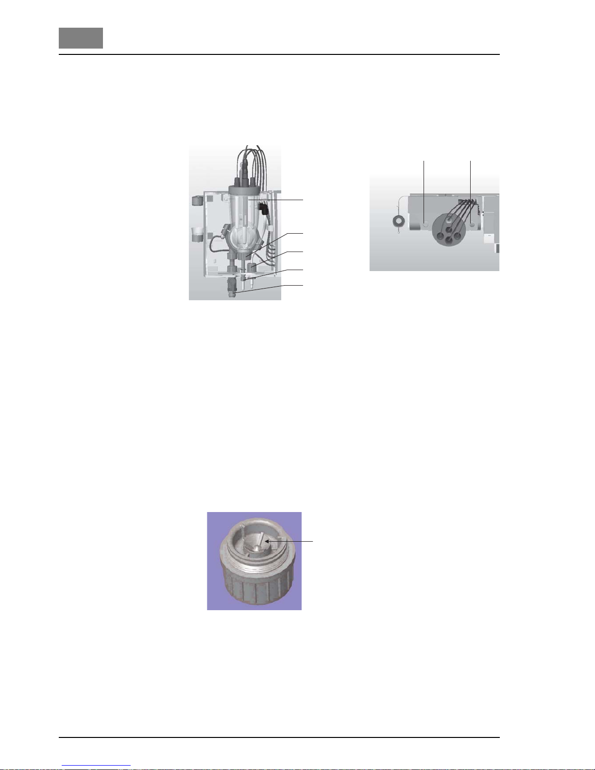
82 WT.050.570.000.DE.IM.0714
Maintenance DEPOLOX® Pool
1.5
Replacing the cell sand
(every 6 months)
The cell sand required for constant cleaning of the chlorine sensor
grinds itself down with time until it is very fine. It must therefore be replaced regularly. The cell sand is supplied in a plastic bottle, the cap
serves as a measure.
Fig. 20
1. Close the ball valve on the sample water inlet (5, Fig. 20). On the
pressurised version also close the stop valve on the sample water
outlet (3, Fig. 20).
2. On the drain (4, Fig. 20) remove the drain screw and empty the cell
body (1, Fig. 20). On the pressurised version temporarily loosen a
plug or sensor to allow air to flow in.
3. When the cell body is empty, rinse the drain screw to remove the
sand and screw it in place again.
4. Remove the housing cover of the flow block assembly. To this purpose press the two buttons (1, Fig. 21) on the top of the housing.
5. Unscrew the flow distributor cap (2, Fig. 20). The remaining water
drips out.
6. Rinse the sand out of the flow distributor cap.
Fig. 22
7. Fill the cap of the cell sand bottle until it is one third full with new
cell sand and pour into the middle of the flow distributor cap (1,
Fig. 22).
8. Screw the flow distributor cap back on.
1
2
3
5
W & T 0 0 0 3 7
4
W & T 0 0 0 3 8
1
1
Fig. 21
1
W & T 0 0 0 3 9
Page 83

DEPOLOX® Pool Maintenance
WT.050.570.000.DE.IM.0714 83
1.5
9. Open the ball valve on the sample water inlet and if necessary the
sample water return line. The cell body fills with sample water once
more. A rotating air bubble does not affect measurement, it disappears on its own.
10. Replace the housing cover and click into place.
After 2 to 3 hours running-in time perform chlorine zero point calibration. If necessary repeat the chlorine zero point calibration after 24
hours.
Total chlorine sensor:
Replace the electrolyte
Replace the membrane
cap
CAUTION!
Do not touch or damage the reference electrode and keep it clean!
Before unscrewing the membrane cap 3, remove the elastomer seal 5
to allow air into the vent hole 4. Not doing this will cause a vacuum to
occur which will damage the membrane. Do not remove the yellowgrey layer on the reference electrode 8. Do not move the yellow-grey
layer towards the gold working electrode 7!
1. Open the sensor. Before unscrewing the membrane cap 3, remove
the elastomer seal 5 to allow air into the vent hole 4.
2. Pour away the electrolyte.
3. Clean the reference electrode 8 with distilled water and dry with a
clean paper towel.
4. Fill the membrane cap 3 to the top with the enclosed electrolyte
(special electrolyte for brine application! Refer to the chapter Spare
partes).
1 Counter electrode 5 Elastomer seal
2 Electrode finger 6 O-ring
3 Membrane cap 7 Gold working electrode
4 Vent hole 8 Reference electrode
5. Clean the gold working electrode 7 with the enclosed lapping paper (special abrasive paper). To do this, place the special abrasive
paper on a paper towel. While holding on to a corner of the paper
move the tip of the electrode of the vertically held probe one or two
times over the rough side of the special abrasive paper.
6. Ensure that the elastomer seal 5 completely covers the vent hole.
7. While holding the electrode shaft in a vertical position, screw on the
cap onto the shaft. Surplus electrolyte will escape through the vent
hole 4 in the membrane cap below the elastomer seal. Do not hold
the vent hole 4 or press on the elastomer seal 5! The membrane
cap must be completely screwed to the electrode shaft so that no
gap remains between membrane cap and electrode shaft.
8. Wash away the escaped electrolyte with water.
9. The sensor requires a 1-2 hour run in time before a first calib ration
can be performed. The final calibration should be done after 1 day.
1
2
3
4
8
7
6
5
Page 84
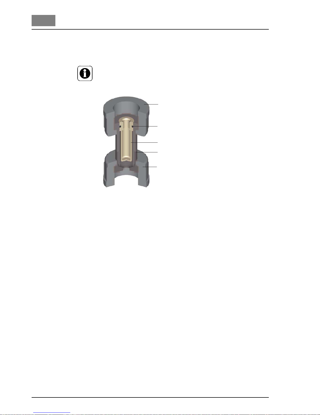
84 WT.050.570.000.DE.IM.0714
Maintenance DEPOLOX® Pool
1.5
Cleaning/replacing
the fine filter
The fine filter must be cleaned or replaced in order to protect the delicate membrane of a membrane sensor against soiling or damage.
NOTE
A fine filter must only be installed when membrane sensors are employed.
Fig. 23 Filter unit
1. Release the knurled nuts (1, Fig. 23)
2. Remove the filter unit (4).
3. Remove the fine filter (3). To this purpose
Screw the M6 screw slightly into the fine filter and pull the fine
filter out of the filter unit
or
Press the fine filter with a suitable tool (not pointed) out of the
filter unit.
4. Rinse the fine filter with water, replace if necessary
5. Place the fine filter into the filter unit. Ensure that the O-ring (2) is
fitted correctly.
6. Fit the filter unit. Ensure that it is fitted in the correct position
(Fig. 23).
7. Tighten the knurled nuts.
1
2
3
1
4
Page 85

DEPOLOX® Pool
WT.050.570.000.DE.IM.0714 85
2 Part 2 Installation and Commissioning
Part 2
Installation and
Commissioning
Page 86

DEPOLOX® Pool
86 WT.050.570.000.DE.IM.0714
Page 87

DEPOLOX® Pool Scope of Supply
WT.050.570.000.DE.IM.0714 87
2.1
2.1 Scope of Supply
The scope of supply includes the following, depending on the individual
order:
Electronic module
Flow block assembly, pressurised or non- pressurised
Mounting set, comprising:
Eight screws Ø 5 mm
Eight dowels Ø 8 mm
Mounting rail
Strips for LED marking (Application 1 ... 4)
Accessory set, comprising:
2 cable terminal screws
6 blind terminal screws
Bushes for closing the ducts for the sensor cables on the elec-
tronic module which are not required
1 seal (2x Ø6 mm)
1 reduction ring Ø 8 mm
2 fuses
Sensors with accessories (depending on order):
Free chlorine (Cl
2
)
pH value
Redox
Conductivity
T otal chlorine (TC1)
Operating manual
Concise instructions
Page 88

88 WT.050.570.000.DE.IM.0714
Scope of Supply DEPOLOX® Pool
2.1
Page 89

DEPOLOX® Pool Technical Data
WT.050.570.000.DE.IM.0714 89
2.2
2.2 Technical Data
2.2.1 Electronic module
Housing Dimensions (W x H x D): 320 x 270 x 175 mm
Weight: approx. 5 kg
Protection category: IP 67
Platform Mains connection
200 ... 240 V AC ± 10 %, 50-60 Hz, 30 VA, fuse 1A (T) type: TR5
100-120 V AC ± 10 %, 50-60 Hz, 30 VA, fuse 1A (T) type: TR5
24 V DC ± 20 %, 30 W, fuse 2.5 A (T) type: TR5
Insulation
Overvoltage category 2
Contamination level 2
Operating conditions
Ambient temperature 0 ... 50 °C
Environment No direct sunlight
Atmospheric pressure 75 ... 106 kPa
max. altitude 2000 m
Relative humidity <80%, not condensing
Storage temperature -20 ... +70 °C
Noise emission < 45 dB
Digital inputs 3 x for floating contact (< 100 Ohm)
Power supply through DEPOLOX
®
Pool
D1: Sample water monitoring
D2: Freely selectable in menu
D3: Freely selectable in menu
input open: digital input activ
input closed digital input not activ
Measurement inputs 1 x Temperature input PT 1000 (0 ... 50 °C) with sensor error display
1 x Feedback input
Positioner position feedback
Potentiometer 1 kOhm
5 x Measurement value input
Direct plug connector for plug-in cards of the sensor measuring
module
Free chlorine
Total chlorine
pH value
Redox pot ential
Conductivity
Page 90

90 WT.050.570.000.DE.IM.0714
Technical Data DEPOLOX® Pool
2.2
Relay plug-in card 1 x Direct plug connector for 8-fold relay plug-in card
Storage temperature: -20 ... +70 °C
Operating temperature: 0 ... +70 °C
8 x Controller outputs
Switching values
5 A, 250 V AC, 1250 VA max
5 A, 220 V DC, 150 W max
UL/CSA-rating
5 A, 1/6 HP 125, 250 V AC
5 A, 30 V DC, 30 W max
1 A, 30 V DC - 0.24 A, 125 V DC
Analog outputs plug-in
card
1 x Direct plug connector for 4-fold analog outputs card
Storage temperature: -20 ... +70 °C
Operating temperature: 0 ... +70 °C
Calibration: Pre-calibrated
4 x Outputs (freely configurable)
Output 0 / 4 ... 20 mA
Accuracy < 0.5 % FS
Load max. can be switched over 1000 Ohm / 400 Ohm
Temperature drift max. 0.2 % / 10 °C
Load monitoring
Electrically isolated up to 50 V to ground
Interfaces 1 x RS232 for direct printer control or for firmware update (not electri-
cally isolated)
1 x RS485 for connection to:
ChemWeb server
OPC Server Data Access V2.0
CMS software 2.2
SECO-S7
Electrically isolated up to 50 V to ground
1 x IRDA for remote calibration with the photometer P42 i-cal (isola-
ted)
Display and
operating unit
1 x Operating panel with 9 keys
8 x Red LEDs for indication of operating conditions
1 x Green LED for indication of the power supply
1 x Graphic display
Resolution 240 x 64 pixels
Green background illumination
Page 91

DEPOLOX® Pool Technical Data
WT.050.570.000.DE.IM.0714 91
2.2
2.2.2 Flow block assembly
Housing Dimensions (W x H x D): 215 x 375 x 155 mm
Weight: approx. 1.5 kg
Connections Sample water: PVC hose 6 x 3 mm
or
PE hose 6 x 1 mm
Thread connection: 1/2"
Flow control valve Flow rate: approx. 33 l/h (controlled)
Control range: 0.2 ... 4.0 bar
Back-pressure: non-pressurised
or
1.5 bar (pressurised)
Sample water temperature: +50 °C max.
Multi-sensor Switching point: 21 l/h ± 3 l/h
Switching hysteresis: 2 l/h
Temperature sensor: PT 1000
Page 92

92 WT.050.570.000.DE.IM.0714
Technical Data DEPOLOX® Pool
2.2
2.2.3 Sensor measuring modules
NOTE
All sensor measuring modules are electrically isolated to 50 V to
ground.
Free chlorine Design (sensor): 3 electrode sensor with additional
electrolyte salt stock
Principle of operation: Potentiostatic amperometry
Temperature compensation: 0 ... +50 °C
Temperature drift: 0.2 %/10 K max.
Calibration: Pre-calibrated
Measuring range: 1 ... 20 mg/l max. (can be scaled freely)
Upot: 0 ... +1000 mV
Input signal: -7 ... 1000 µA
Storage temperature: -10 ... +30°C
Conductivity of the sample water: 200 µS/cm ... 200 mS/cm
Total chlorine
(only non-pressurised)
Design (sensor): 3 electrode sensor
membrane-covered (TC1)
Principle of operation: Potentiostatic amperometry
Temperature compensation: internal temperature compensation
5 ... +45 °C
Temperature drift: 0.2 %/10 K max.
Calibration: Pre-calibrated
Measuring range: 0.05 ... 20 mg/l (ppm) chlorine and
chloramines
Input signal
(plug-in card): -7 ... 1000 µA
Storage temperature: -10 ... +45°C (without electrolyte)
Conductivity of the sample water:
with standard electrolyte W3T171793: <2500 µS/cm
with brine electrolyte W3T164805: 2.5 - 60 mS/cm
Page 93

DEPOLOX® Pool Technical Data
WT.050.570.000.DE.IM.0714 93
2.2
pH value Temperature compensation: 0 ... +50 °C
Temperature drift: 0.2 %/10 K max.
Calibration: Pre-calibrated
Measuring range: 0 to 5 pH ... 9 to 14 pH
(can be freely scaled in 1 pH value steps)
Input signal
(plug-in card): -1000 ... +1000 mV
Input resistance: 5 x 10
11
Ohm
Storage temperature: -5 ... +30°C
Redox potential Temperature compensation: 0 ... +50 °C
Temperature drift: 0.2 %/10 K max.
Calibration: Pre-calibrated
Measuring range: 0 to 400 mV ... 500 to 1000 mV
(can be freely scaled in 100 mV steps)
Input signal
(plug-in card): -1000 ... +1000 mV
Input resistance: 5 x 10
11
Ohm
Storage temperature: -5 ... +30°C
Conductivity Design (sensor): LF325
Temperature compensation: 0 ... +50 °C
Calibration: Pre-calibrated
Measuring range: 2500 µS/cm
10, 20, 50, 100 mS/cm
Storage temperature: -5 ... +90°C
Page 94

94 WT.050.570.000.DE.IM.0714
Technical Data DEPOLOX® Pool
2.2
Page 95

DEPOLOX® Pool Transport, Storage
WT.050.570.000.DE.IM.0714 95
2.3
2.3 Transport, Storage
Transport The device is supplied in standard packaging. During transport the pa-
ckaged device must be handled carefully and should not be exposed to
wet weather or moisture.
Check that the transport packaging is undamaged.
In the event of damage please inform the transport company immediately, as your rights to compensation will otherwise be lost.
If the device is damaged, please contact your contractual partner immediately.
Keep the packaging until the system has been correctly installed and
taken into operation.
Storage Store the device and the sensors in a dry condition without any residual
water in a dry place which is not exposed to the weather. Refer to
"Technical Data" for information on the storage temperature.
Page 96

96 WT.050.570.000.DE.IM.0714
Transport, Storage DEPOLOX® Pool
2.3
Page 97

DEPOLOX® Pool Installation
WT.050.570.000.DE.IM.0714 97
2.4
2.4 Installation
Installation site The device must be protected against rain, frost and direct sunlight and
may therefore not be installed outdoors.
It must be mounted horizontally on a flat wall in a frost-free room with
an ambient temperature of 0 to 50 °C.
The air in the room should be non-condensing.
Opening the housing 1. Remove the housing cover of the flow block assembly. To this pur-
pose press the two buttons on the top of the housing.
2. Release the five screws on the cover of the electronic module.
CAUTION!
The indication and operating elements on the cover of the electronic
module are connected to the housing with wires.
NOTE
The device switches off automatically when the cover is removed.
3. Carefully remove the cover of the electronic module and leave to
hang on the strain relief.
Closing the housing 1. Tighten the housing screws with max. 0,7 Nm (±0,15 Nm).
Page 98
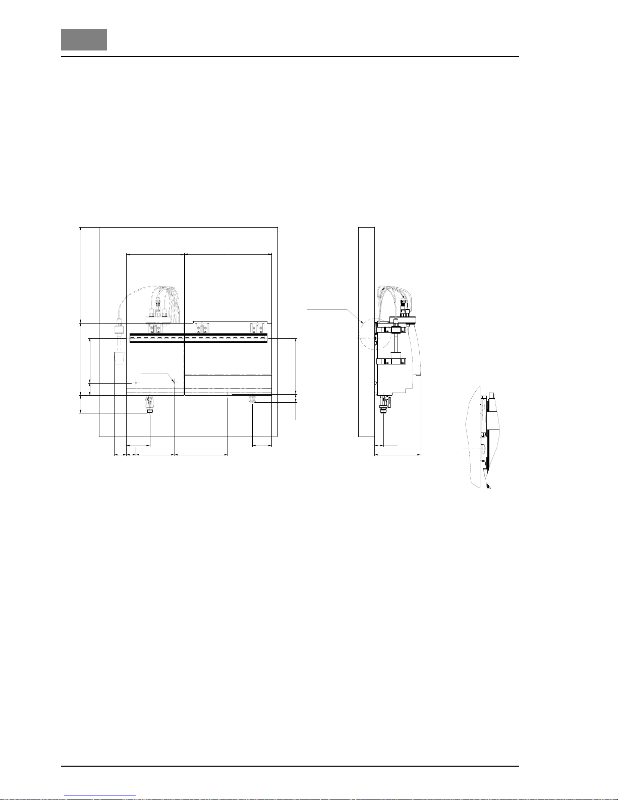
98 WT.050.570.000.DE.IM.0714
Installation DEPOLOX® Pool
2.4
1. Secure the mounting rail with two screws (diameter 5 mm) and two
dowels (diameter 8 mm) to the wall.
2. Hook the electronic module onto the mounting rail so that it is flush
at the right and secure with a screw (diameter 5 mm) and a dowel
(diameter 8 mm) to the wall.
3. Hook the flow block assembly onto the mounting rail next to the
electronic module and secure with two screws (diameter 5 mm)
and two dowels (diameter 8 mm) to the wall.
D e t a i l X
S I E H E D E T A I L X
2 1 0
3 1 6
3 5 02 6 3
4 5 1 6 3
6 5
4 5
8 5
3 5 1 4 0 1 9 4
3 0 , 5 2 0 3 , 5
3 2
1 7 0
ø 5 , 5
7 0
Fig. 24
Installation with moun-
ting rail
Page 99
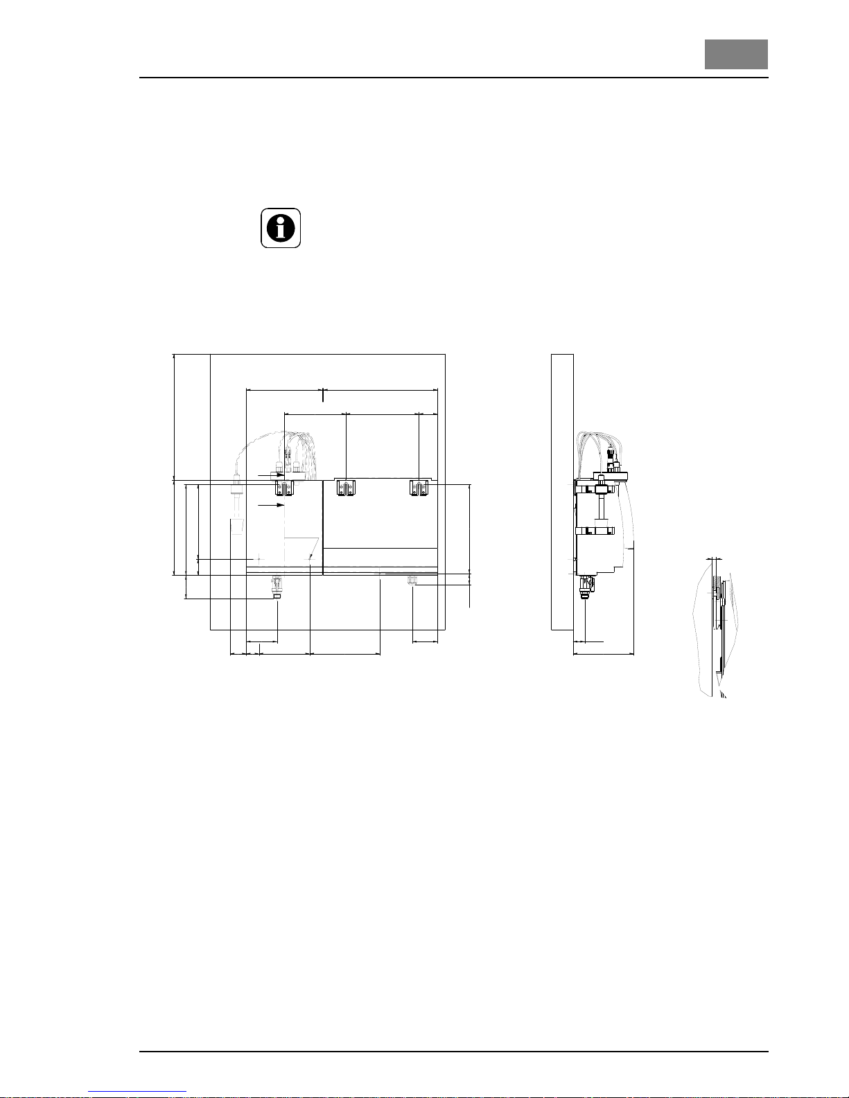
DEPOLOX® Pool Installation
WT.050.570.000.DE.IM.0714 99
2.4
The electronic module and the flow block assembly can be mounted in
different places, the modules can be hooked onto suitable tallow-drop
screws by the top holding fixtures instead of onto the mounting rail.
Subsequent installation procedures are described above.
NOTE
If the electronic module and the flow block assembly are mounted at separate locations, the sensor cable extensions with a maximum length
of 50 m must be used. An impedance converter for the Redox and pH
sensors is also required (part no. W3T165563).
B
B
S c h n i t t B - B
2 1 0 3 1 6
3 5 02 6 3
4 5
6 5
4 5
8 5
3 5 1 4 0 1 9 4
3 0 , 5
3 2
1 7 0
ø 5 , 5
7 0
2 0 7
2 5 2
2 4 7
5 1 , 52 0 21 7 0 , 5
3 , 5
Fig. 25
Installation version wit-
hout
mounting rail
Page 100

100 WT.050.570.000.DE.IM.0714
Installation DEPOLOX® Pool
2.4
 Loading...