


Installation & User Instructions:
Model: e500 - e600s – e600gf – e700s – e710 – e800gf/2/3 – e1000s – e1000gf –
e1030gf/2/3 – e1500gf/2/3 – e1800gf/2/3
Once installed, the installer should take the appropriate steps
To ensure that the user understands how the appliance operates and
Should make the customer aware of the appliances basic service requirements.
Please note: this product is only suitable for well insulated spaces or occasional use.

Safety:
This appliance is not intended for use by persons (including children) with reduced physical, sensory or mental capabilities, or lack of experience
and knowledge, unless they have been given supervision or instruction concerning the use of the appliance by a person responsible for their
safety.
Children should be supervised to ensure that they do not play with the appliance.
General Warnings:
Never leave children unsupervised with an unguarded heater.
Never obstruct or cover the heater outlet.
Never install or use this product where it may come in contact with water i.e. a bathroom or wet room.
Never use aerosols or steam cleaners near this product.
Never route the electric cable near the heater outlet.
Never route the electric cable under carpets or floor coverings.
Never install this product close to curtains or combustible materials.
Never Use the heater to dry clothes or other objects.
Never remove the fireplace surrounding without isolating the electric supply.
Important electrical safety:
This appliance must never be installed above or in front of a fixed electric socket.
The electrical socket must be easily accessible to isolate the supply during maintenance and cleaning.
This appliance is supplied with a two meter power lead, which has a 13Amp moulded three pin plug to connect to a standard 230/240V plug
socket.
This appliance must always be earthed. If in any doubt consult a suitably competent person.
All Evonic fires products meet the requirements of the EC Directives 2004/108/EC and 2006/95/EC.
These directives have been met by compliance with the following standards:
BS EN 60335-1:2002
BS EN 60335-2-30:2003
BS EN 6100-6-3:2001
Please read these instructions before installation or use and keep this booklet handy for future reference.
1
Servicing:
Only a competent person should service this appliance.
We recommend that this appliance is serviced every 12 months.
Warning: Before carrying out any repairs or servicing, ensure that the power supply cord is removed from the mains supply.
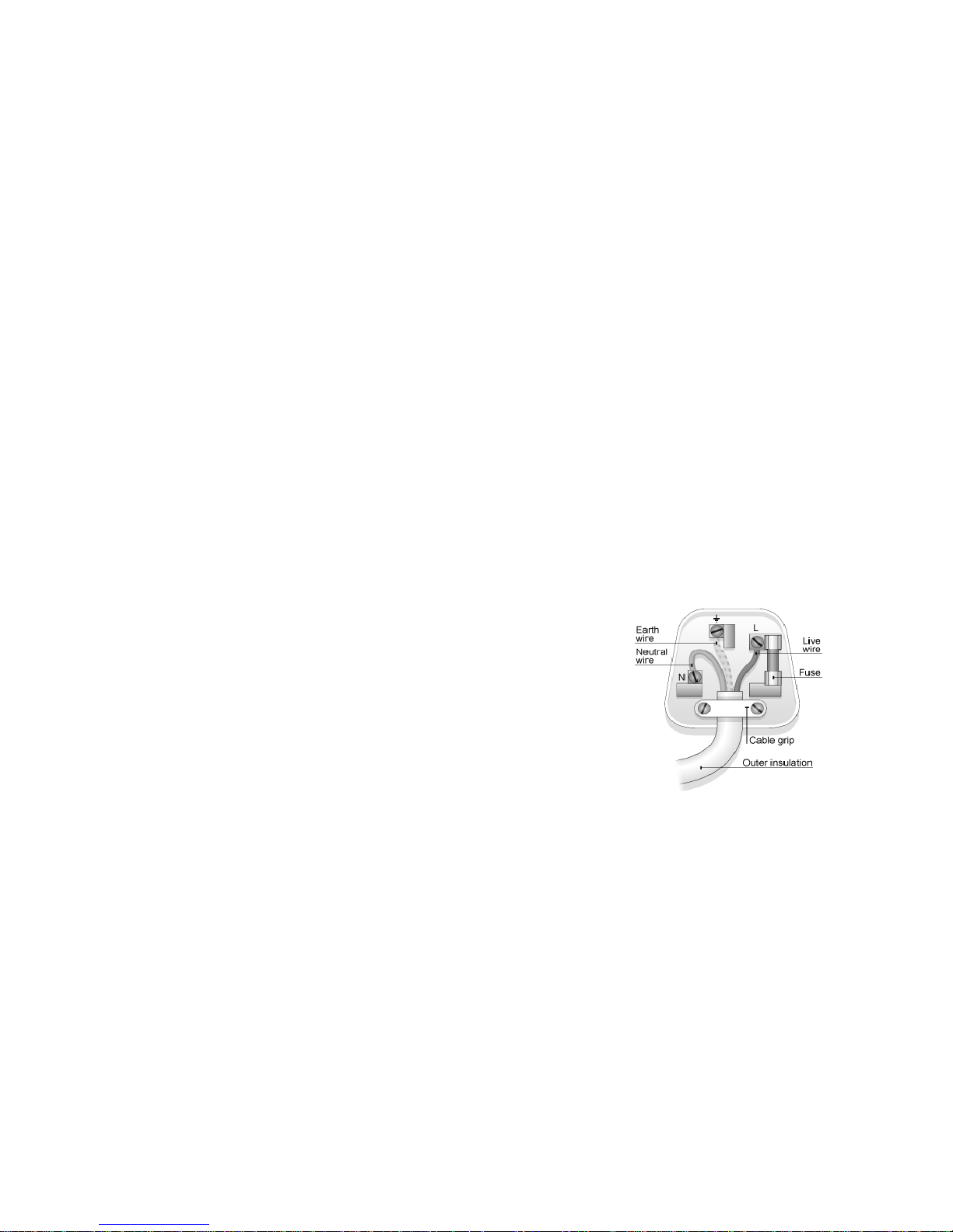
• The green and yellow wire must be connected to the terminal in the plug which is marked
with the letter E or the earth symbol.
• The blue wire must be connected to the terminal in the plug marked with the letter N.
• The brown wire must be connected to the terminal in the plug marked with the letter L.
• If the plug is damaged, replace or consult a qualified electrician.
• Replace fuses only with fuses of the correct size and rating.
As the colours of the mains lead of this appliance may not match the coloured markings used to identify the terminals in a plug, please observe
the following:
Replacement plug: (Please note that it will invalidate your warranty if the moulded plug is removed and connected to a fused spur by
an unqualified person)
This appliance must only be connected to a 230/240 Volts AC 50Hz supply. Before connecting the fire, check that the supply voltage is the same
as stated on the fire. This appliance must only be used on a AC supply, fuse rating 13Amp.
The wires in the mains lead are coloured in accordance with a standard UK supply, these being:
GREEN/YELLOW – EARTH
BLUE – NEUTRAL
BROWN – LIVE
2

INSTALLATION REQUIREMENTS:
BUILT IN MODELS:
This product has been designed to be installed into a studwork or existing chimney breast.
Please note that any GF2 models from the e-series range are not suitable to be installed into a existing chimney breast.
Please seek advice from a professional, with reference to the structural integrity of the installation site.
If the products is to be installed into a open chimney or flue, it is important that the chimney/flue is blocked off to prevent any up/down draughts
and falling debris which could restrict and alter the airflow to the product.
It is also important to ensure that the product has a minimum internal clearance directly above and below the product of 50mm, this is to ensure
that the product can circulate the required airflow for the heater unit.
The product should never be sealed into a opening with the use of silicones or adhesives as this can also alter the airflow and hinder any further
servicing of the product.
Please refer to technical specification table for further information, with reference to measurements.
(Heater unit cut-out) (This is a safety feature, to safe guard against further damage to the product).
If the airflow is restricted the heater will automatically turn off. This is can occur due to incorrect installation or obstruction.
To reset the heater function:
•isolate from the mains power supply.
•Leave product to cool.
•After a suitable cooling down period, remove the obstruction if obstructed, and check installation.
•After 10 minutes the thermo switch (cut-out) in the heater will reset.
Please note that both the effect fan and heater fan omit a low decibel noise, both of which are normal operating characteristics.
3

Studwork / Installation Method
All e-series products require an internal aeration clearance of 100mm minimum of 50mm directly above and below the main product casing. (Failing to do so can cause issues with the heat & flame
function).
• Each e-series product comes complete with one or more wall mounting brackets.
• Establish the desired finished height from floor level of the e-series product. (Note: minimum distance from floor level is 300mm).
• Fix the wall bracket to the wall ensuring to use the correct fixings given the wall construction, Studded or solid wall.
• Hang the e-series product onto the bracket and secure the product into position using the wall brace brackets located at the top of the product.
• Ensure that the IEC power lead is connected and pushed in firmly to the IEC socket. (Note: The appliance should ideally be located close to a suitable mains socket to enable connection
It is important that the mains socket is external from the installation site, this should be easily accessible to allow disconnection when the appliance is fitted).
• Once the product is secured to the wall and connected to the power supply, the false construction (Chimney Breast) can be formed around it.
• Build the studwork chimney breast or enclosure to the desired size See page 5 for minimum opening sizes ref: - Fig:1 and table:1.
• It is important to allow for the finished face when setting the depth of the frame construction.
• It is essential to include a header at the required height to ensure the appliance does not support the weight of the finished wall.
• Prepare the cut out in the plaster board / finishing board, and install ensuring that the plaster kit edges are fitting to the inside of the cut out of the board.
Wall Brace brackets:
Wall Bracket or brackets:
The Qty of wall brackets will vary
dependent on model.
Plaster kit edges:
4
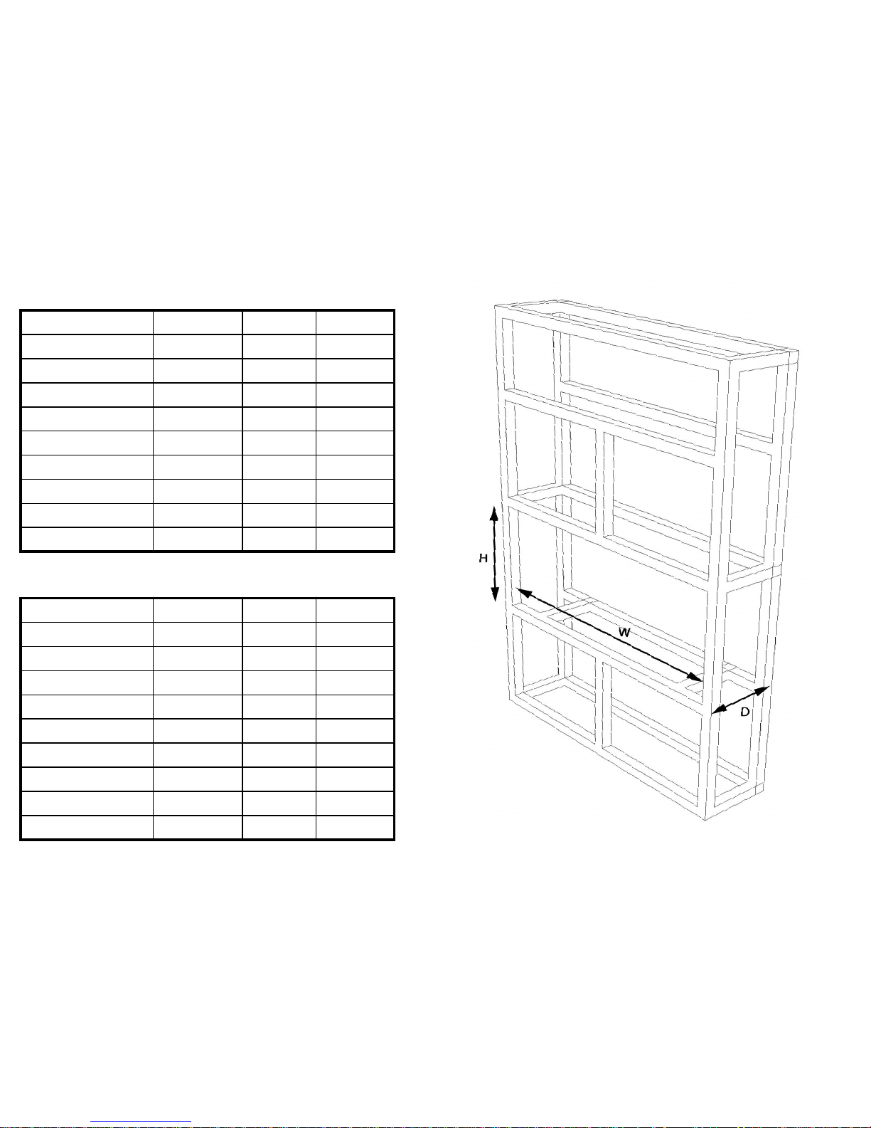
The below table contains minimum opening sizes required.
Model W D H
e500gf3 530mm 305mm 610mm
e600s/gf 690mm 185mm 640mm
e700s 680mm 185mm 480mm
e710s 760mm 185mm 790mm
E800gf/2/3 835mm 305mm 790mm
e1000s/gf 1055mm 185mm 475mm
e1030gf/2/3 1065mm 305mm 560mm
e1500gf/2/3 1565mm 305mm 560mm
e1800gf/2/3 1785mm 305mm 615mm
Fig:1
Model W D H
e500gf3 495mm 305mm 400mm
e600s/gf 637mm 185mm 455mm
e700s 640mm 185mm 285mm
e710s 710mm 185mm 607mm
E800gf/2/3 802mm 305mm 590mm
e1000s/gf 1003mm 185mm 275mm
e1030gf/2/3 1003mm 305mm 355mm
e1500gf/2/3 1505mm 305mm 355mm
e1800gf/2/3 1750mm 305mm 410mm
The below table contains the final finished opening sizes once
the product has been installed.
Table:1
5

Front Glass Removal:
To remove the front glass and install the log set, the below steps must be taken.
1. Remove the two screws located in the bottom glass
retaining bar.
2. Remove the bottom glass retaining bar.
3. Remove the glass by pulling the second retaining bar away from the body of the fire, ensure that the glass is supported at all
times. A suction cup has been provided to help aid this step.
(Please note the suction cup is provided for support only, not to hold the full weight of the glass).
(Please note: it is recommended that this step is carried out by two persons on E1500gf/2/3 & E1800gf/2/3 models).
Suction Cup
4. Place the log set as stated and replace the glass by
reversing steps 3. to 1.
6

Continental Log Set Layouts: e1000 / e700 / e600t
Each e1800gf-2-3, e1500gf-2-3, e1030gf-2-3/ e1000s e1000gf/ e700gf e700/ e710 /
e800gf-2-3 / e600s comes as standard with a continental log set.
Please note that the log styles and sizes will vary dependent on model.
The images shown are examples of suggested fuel/log set layouts.
The log set layout can be arranged to personal preference.
e1030gf-2-3/e1000gf-s suggested log layout.
e600gf-s suggested log layout.
7
e1500gf-2-3 suggested log layout.
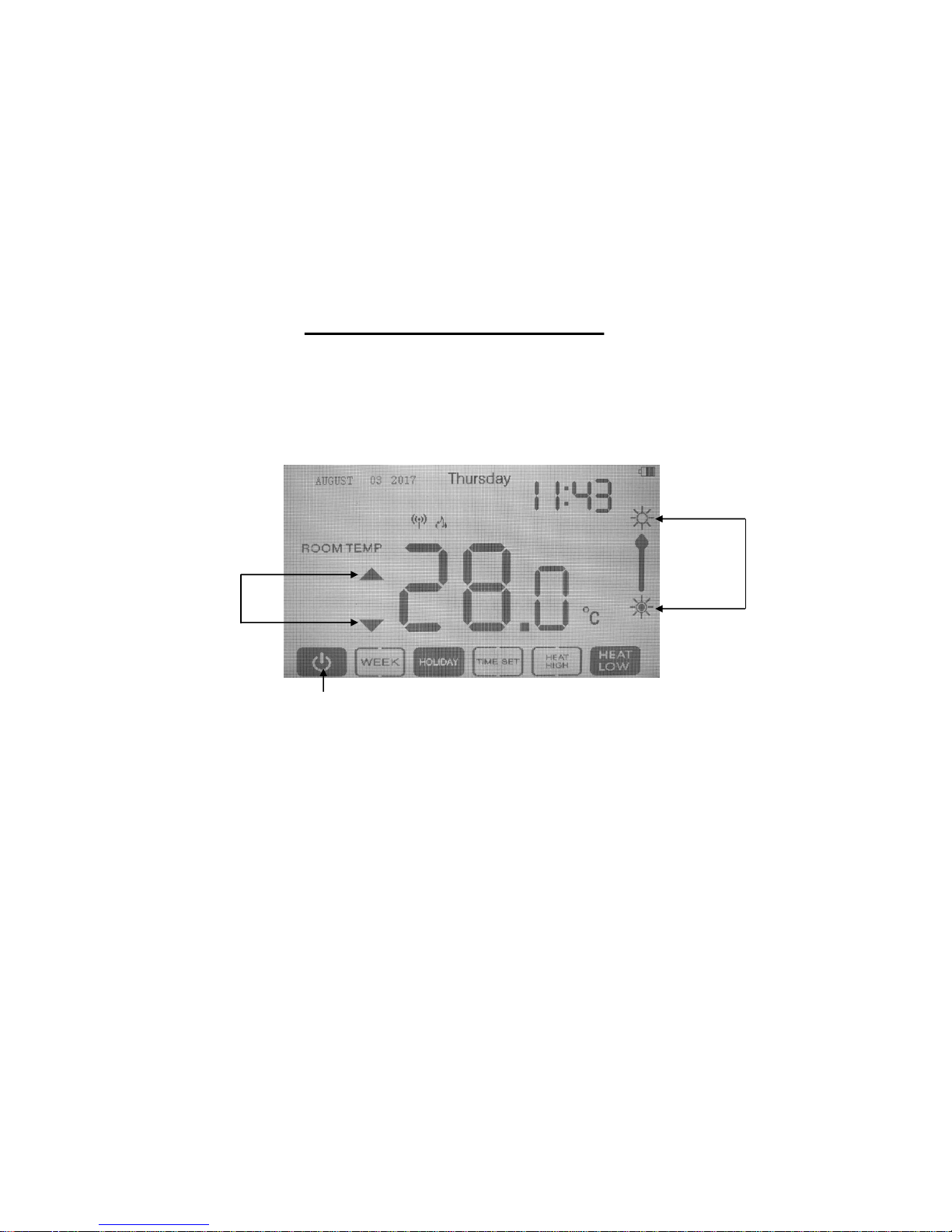
OPERATING INSTRUCTIONS
The appliance is operated by the e-touch control system only, the main standby power switch to the e-series product is located to the
right of the heater outlet, which is marked with a light bulb image, to activate the product, this switch must be switch to the “ON”
position.
The first time the e-series product is activated both the illumination and heater will function, to switch the heater “Off” simply reduce
the Room Temperature down to 10 degrees (shown below) ref: B.
followed by the following actions on the e-touch control system.
8
A.
B.
C.
e-touch Quick Operation:
1). Ensure that the e-touch controller is switch on.
2). Single Press “A” to switch the fire On & Off.
3). Press “B” to adjust the temperature & Heat Output – (The Heater many be running on Initial power up).
4). Press “C” to adjust the LED brightness.
5). For further Operational Options please refer to the e-touch instruction manual.

E1030 Plinth installation:
It is advised that the plinth is installed to the product before installation.
(Wall mounted).
In order to install the plinth to the e1030gf3 please follow the following steps:
1: Screw and fix the grey brackets provided to the front & sides of the E1030GF3 product using the
shortest side of the bracket. (Use the silver screws that are provided). (See Fig1).
2: Lay the 1030gf3 on its back with the front of the product facing up.
3: Carefully slide the plinth in between the silver brackets and the black edge of the E1030gf3.
4: Once the plinth is located & in position, fix the plinth by screwing through the grey bracket into the
bottom of the plinth. (Use the gold screws that are provided). (See Fig3)
Please note that the plinth once installed is not load bearing, it is strongly advised that the
plinth is not sat upon or have any significant weight added to it.
Fig:1 Fig:
9

EXTENDED WARRANTY:
In order to qualify for an additional 12 months warranty, Please complete the form below.
This form must be submitted no later than 30 - days after the purchase of the product.
NAME:
ADDRESS:
MODEL:
SERIAL NO:
DATE OF PURCHASE:
PURCHASED FROM:
ADDRESS:
INSTALLATION DATE:
INSTALLED BY:
Please submit this form along with a copy of receipt or invoice to the below address:
PLEASE NOTE THAT WARRANTY FORMS SUBMITTED WITHOUT A COPY OF RECEIPT OR INVOICE WILL BE NIL AND VOID.
CK Fires Ltd / Evonic Fires
1 Stour house, Clifford park, Clifford lane, Stratford-Upon-Avon, CV37 8HW
Tel: +44 (0) 1789 263868 Fax: +44 (0) 1789 293080
Email: sales@evonicfires.co.uk Follow us on Twitter @evonicfires

Guarantee:
Conditions of warranty:
If this appliance should prove to be defective due to faulty design, materials or workmanship within 24 months of purchase, the product
will be repaired free of charge, subject to the following conditions:
The electric fire shall have been purchased and used solely within the UK and Ireland for domestic purposes and in accordance with
the Users operating instructions.
It is the purchasers responsibility to prove that the unit is under warranty, e.g. receipt of purchase.
All warranties, will be invalidated if unauthorised repairs or modifications are made to the electric fire, or in case of accident, misuse or
damage caused by improper installation, or to damage occurring during transit to or from the repairer and altered or missing serial
numbers.
Any parts, which have been replaced under this warranty, shall become our property.
The company shall not be liable for any consequential loss or damage what so ever, arising from or in connection with this electric fire.
This Warranty does not apply to Heating elements, Bulbs or fuses.
‘No fault found’, service calls and installation errors are not covered under the manufacturers warranty and will result in a charge being
made for the Call-Out by our appointed service engineer.
This warranty is in addition to and does not affect the purchasers statutory rights of consumers.
CK Fires Ltd / Evonic Fires
1 Stour house, Clifford park, Clifford lane, Stratford-Upon-Avon, CV37 8HW
Tel: +44 (0) 1789 263868 Fax: +44 (0) 1789 293080
Email: sales@evonicfires.co.uk Follow us on Twitter @evonicfires
 Loading...