

DETECTIVE S4CIH7D
DVR security monitoring system with four cameras
User's Manual (EN)

- 82 -
1 Production Introduction
1.1 Product overview
The series DVR is designed especially for security and defense field which is an
outstanding digital surveillance product. It introduces embedded LINUX operating
system which is more stable. It introduces standard H.264mp video compressed
format and G.711A audio compressed format which insures the high quality
image, low error coding ratio and single frame playing. It introduces TCP/IP
network technology which achieves the strong network communication ability
and telecommunication ability.
The series DVR can be used individually or online applied as a part of a safety
surveillance network. With the professional network video surveillance software
it achieves the strong network communication ability and telecommunication
ability.
The series DVR can be applied in the bank, telecom, electric power system,
judicial system, transportation, intelligent housing, factory, storehouse, water
conservancy and so on.
1.2 Main functions
Real-time surveillance
spot interface, analog interface, VGA interface and HDMI interface,
surveillance function through monitor or display.
Storage
non-working hard disk dormancy processing which is convenient to
radiate heat, reduce power and extend the life-span
special storage format which insures the data safety
Compression
real-time compression by individual hard disk which insures the audio
and video signal stable synchronization
Backup

- 83 -
through USB interface such as USB equipment, removable hard disk
and so on
through net download the files in the hard disk
Playback
individual real-time video recording as well as searching, playback,
network surveillance, recording check, downloading and so on
multi-playback mode
zoom at arbitrary region
Net operating
through net tele-surveillance in the real time
tele-PTZ control
tele-recording check and real-time playback
Alarm linkage
Alarm activated video record, tour ,message, buzzer, e-mail, ftp
Communication interface
RS485 interface which fulfills the alarm input and PTZ control
Intelligent operating
mouse action function
fast copy and paste operating for the same setting
2 Open-package check and cable connections
2.1 Open-package check
Front panel and rear panel
The key function specification in the front panel and the interface
specification in the real panel are in the specification.
Please check the product type in the front panel whether is accordant
with the product type you order.
The label in the real panel is very important for the after service. Please
protect it carefully. When you contact us for after service, please provide the

- 84 -
product type and serial number in the label.
2.2 Hard disk installation
For the first use, please install the hard disk, this machine box can install two
hard disk (no limited capacity).
For the first use,please install the hard disk.
1. Remove case screw 2. Remove cover 3. Install SATA hard disk
4. Connect SATA data cable 5. Connect SATA power cable 6. Replace cover
7. Replace screws
2.3 Front panel
- 85 -
(1) IR remote receiver
(2) Power indicator light
(3) Previous file
(4) HDD indicator light
(5) Next file
(6) PTZ
(7) Slow play
(8) HDD Info
(9) Fast play
(10) Backward pause
(11) Record
(12) Play and Pause
(13) Function switch
(14) Search video
(15) USB
(16) ESC
(17) Left
(18) Up
(19) Down
(20) Menu/Enter
(21) Right
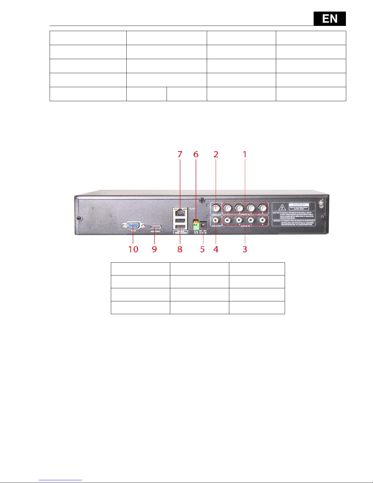
2.4 Rear panel
(1) Video input
(2) Video output
(3) Audio input
(4) Audio output
(5) Power
(6) RS-485
(7) RJ-45
(8) USB
(9) HDMI
(10) VGA
- 86 -
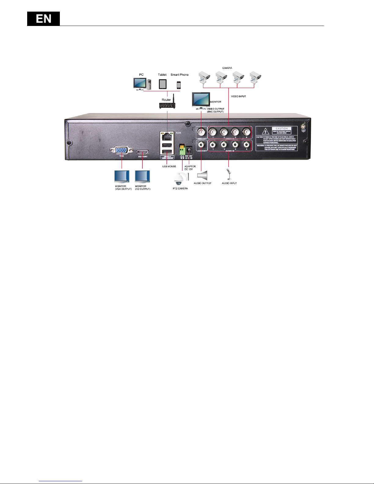
2.5 Full Connectivity Diagram
2.6 Audio and video input and output connections
2.6.1 Video input connections
The video input port is BNC connector plug. The demand of input signal is
PAL/NTSC BNC(1.0V
P-P
,75Ω).
The video signal must be accorded with the state standard which has the high
signal to noise ratio, low aberration and low interference. The image must be
clear and has natural color in the appropriate brightness.
Insure the video signal stable and credible
The video should be installed in the appropriate location where is away from
backlighting and low illumination or adopts the better backlighting and low
illumination compensation.
The ground and power supply of the video and the DVR should be shared and
stable.
Insure the transmission line stable and credible
The video transmission line should adopt high quality coaxial pair which is
chosen by the transmission distance. If the transmission distance is too far, it
should adopt shielded twisted pair, video compensation equipment and

- 87 -
transmit by fiber to insure the signal quality.
The video signal line should be away from the electromagnetic Interference
and other equipments signal lines. The high voltage current should be avoided
especially.
Insure the connection stable and credible
The signal and shield lines should be firm and connected credible which avoid
false and joint welding and oxidation.
2.6.2 Video output connections and options
The video output is divided into PAL/NTSC BNC(1.0V
P-P
,75Ω) and VGA
output (selective configuration).
When replace the monitor by the computer display, there are some issues to
notice
1. Do not stay in the turn-on state for a long time.
2. Keep the computer display normal working by demagnetizing regularly.
3. Stay away from the electromagnetic Interference.
2.6.3 Audio signal input
Audio port is BNC connection.
The input impedance is high so the tone arm must be active.
The audio signal line should be firm and away from the electromagnetic
Interference and connected credible which avoid false and joint welding and
oxidation. The high voltage current should be avoided especially.
2.6.4 Audio signal output
Commonly the output parameter of DVR audio signal is greater than 200mv
1KΩ(BNC) which can connect the low impedance earphone and active sound
box or other audio output equipments through power amplifier. If the sound
box and the tone arm can not be isolated, howling phenomena is often
existed. There are some methods to deal with the above phenomena.
1. Adopt better directional tone arm.
2. Adjust the sound box volume to be under the threshold that produces
the howling phenomena.

- 88 -
3. Use fitment materials that absorb the sound to reduce reflection of the
sound.
4. Adjust the layout of the sound box and the tone arm.
2.7 PTZ connections
1. PTZ decoder connections
A. The grounding of the PTZ decoder and DVR must be shared otherwise the
common-mode voltage will lead to the PTZ control failure. The shielded
twisted pair is recommended.
B. Avoid the entrance of high voltage. Make the layout reasonably. Take
precaution from the thunder.
C. In the outlying end connect 120Ω resistance paralleled to reduce the
inflection and insure the signal quality.
D. The 485 +/- lines of DVR cannot connected with other 485 output
equipments paralleled.
E. The voltage between the +/- lines of the decoder must be less than 5V.
2. Front equipment grounding note
Incorrect grounding can result in damage to the unit.
3. PTZ input type unlimited
Parameter
Meaning
485T+/A, 485T-/B
485communication interface which is connected with the recording
control equipments such as the decoder
- 89 -
3 Basic operation
Note: Any buttons that are displayed in gray indicates it is not supported.
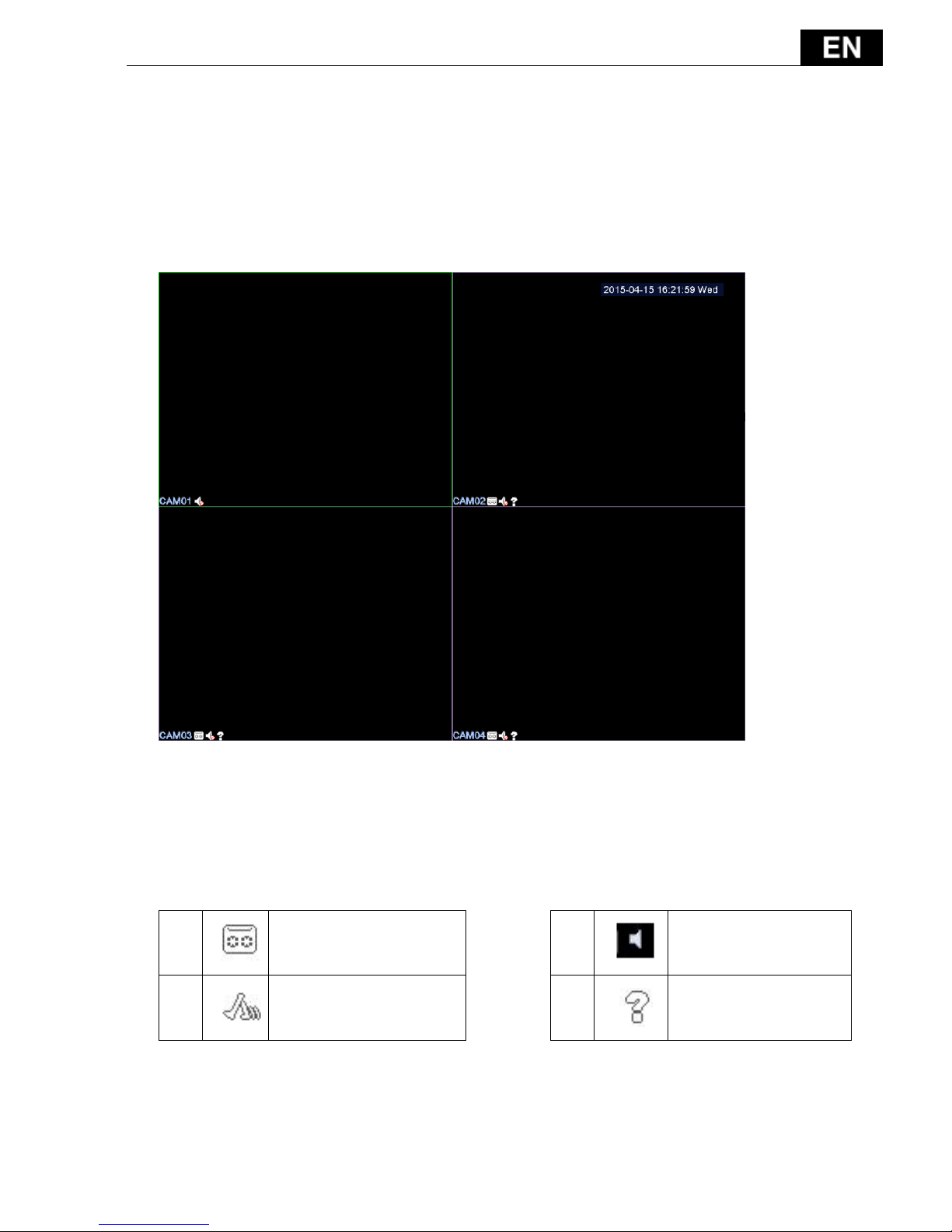
3.1 Preview
Picture3.1 4 Channel Preview
You can right click your mouse to switch between the windows.
The system date, time, channel name, surveillance video, and the alarm
status are shown in each window.
1 Recording status
3 Audio
2 Motion detect
4 Video loss
Table 3.1 Preview icon
- 90 -
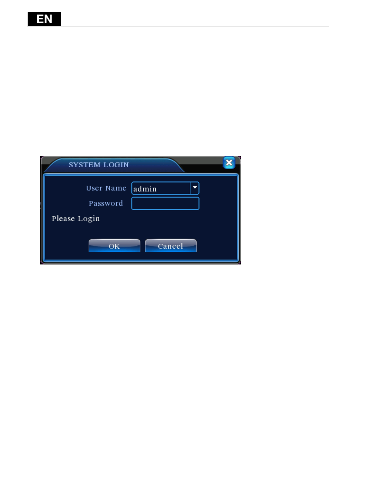
3.2 System Login
When the DVR boots up, the user must login and the system provides the
corresponding functions with the user purview. There are two user settings. The
names are admin, default and these names have no password default. admin is
the super user purview; default’s permissions are preview and video playback.
User admin password can be revised, while their permissions can’t be revised;
user default is the default login user whose permission can be revised but not its
password.
Picture 3.1 System Login
Password protection: If the password is continuous wrong three times, the
alarm will start. If the password is continuous wrong five times, the account will
be locked. (Through reboot or after half an hour, the account will be unlocked
automatically).
For your system security, please modify your password after first login.
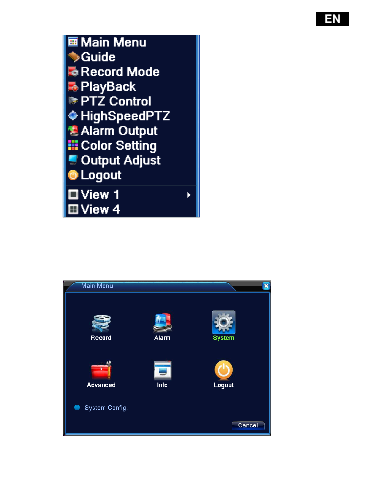
3.3 Desktop shortcut menu
In preview mode you can right click mouse to get a desktop shortcut menu,as
the picture 3.2 shows. The menu includes: main menu, Guide, record mode,
playback, PTZ control, High Speed PTZ, Alarm Output, color Setting, Output
adjust, Logout, view mode.
- 91 -
Picture 3.2 Shortcut Menu
3.3.1 Main menu
When you login, the system main menu is shown as below.
Picture 3.3 Main Menu

- 92 -
3.3.2 Guide
Include IPONE APP/Android APP download link QR-CODE,and DVR ID number
QR-CODE.
3.3.3 Record Control
Please check current channel status: “○” means it is not in recording status,
“●” means it is in recording status.
You can use desktop shortcut menu or click [main menu]> [recording
function]> [recording set] to enter the recording control interface.
Picture 3.8 Record Mode
【Schedule】Record according to the configuration.
【Manual】Click the all button and the according channel is recording no
matter the channel in any state.
- 93 -
【Stop】Click the stop button and the according channel stops recording no
matter the channel in any state.
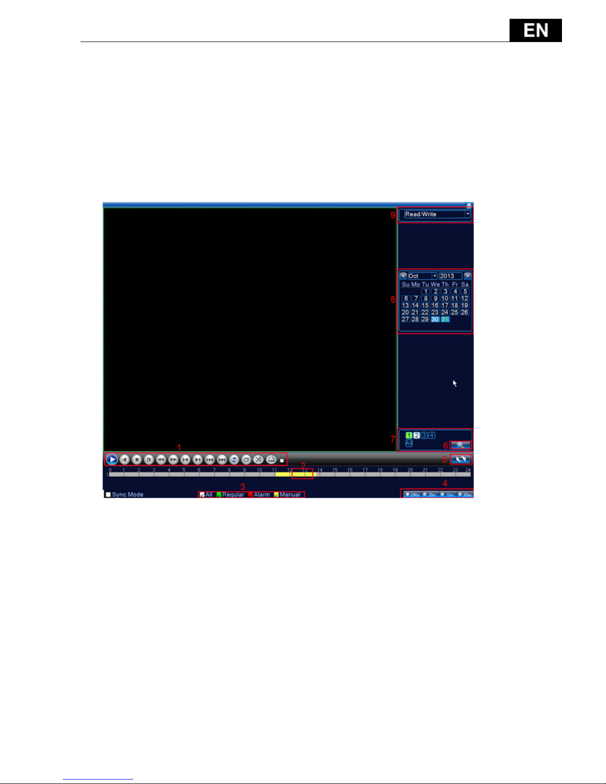
3.3.4 Playback
There are two methods for you to play the video files in the hard disk.
1. In the desktop shortcut menu.
Main menu>Record->Playback
- 94 -
Picture 3.4 video playback
- 95 -
(1) Playback
control
(2) Operation hint
(3) Record
mode
(4) Time interval
choosing
(5) Switch by time,
file mode
(6) File searching
(7) Channel
choosing
(8) Date choosing
(9) Storage device
choosing
(10) File
information
(11) Listed
files
(12) Time searching
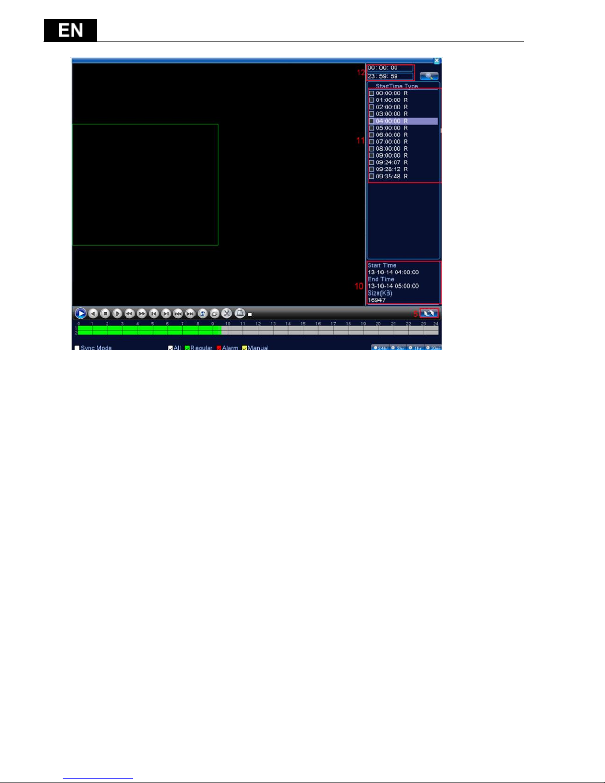
【Listed files】Look up the listed files that accord with the searching criteria.
【File information】Look up the found file information.
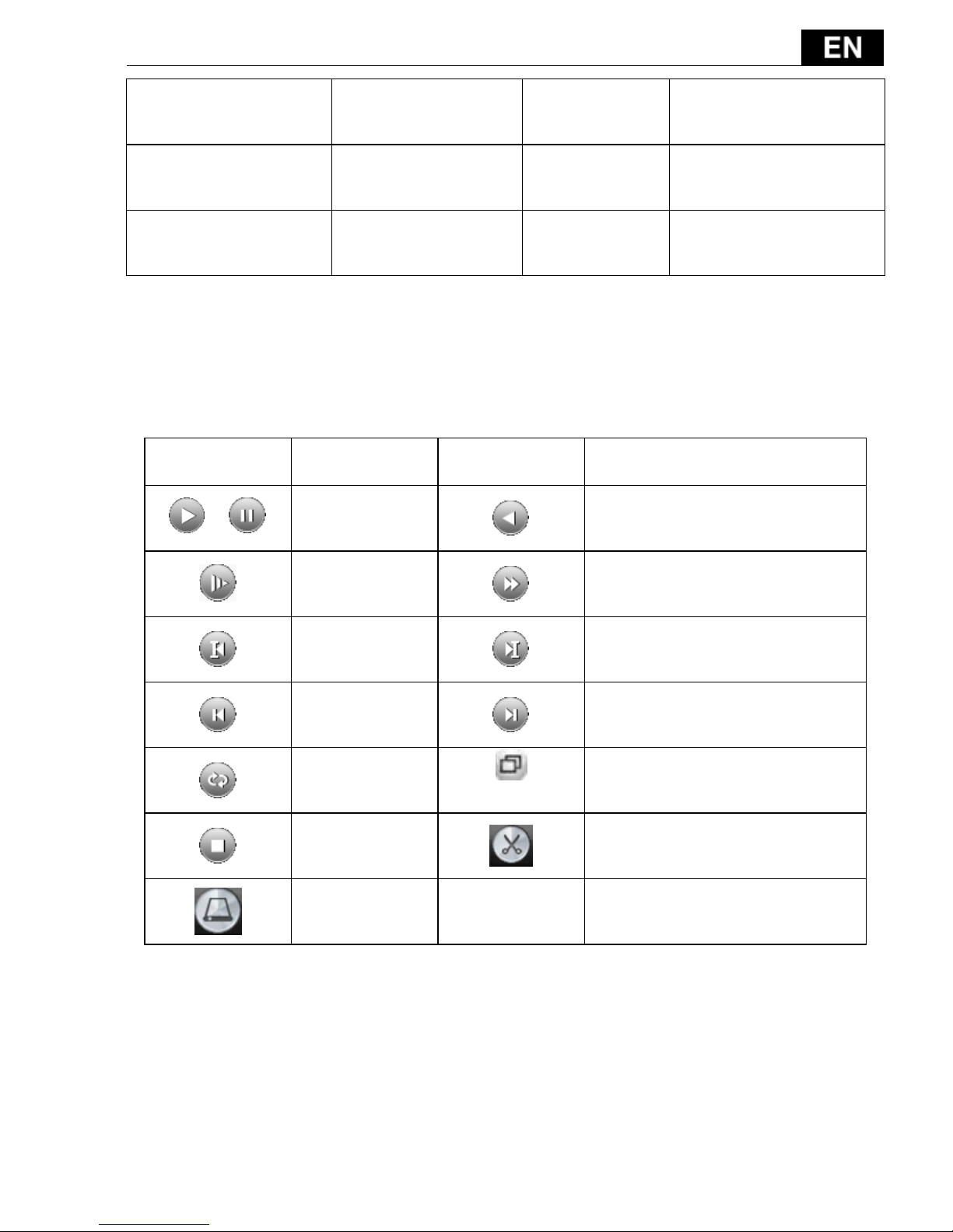
【Playback control】See detail in below chart
Key
Function
Key
Function
/
Play/Pause
Backward play
Slow forward
Fast forward
Previous
frame
Next frame
Previous file
Previous file
Round play
Full screen
Stop Edit
Backup
Picture 3.5 Playback control key
Note: play under frame by frame, the playback status should be paused
firstly.
【Operation tips】show function of the key that cursor placed.
Special functions:
Accurate playback:Input time (h/m/s) in the time column and then click
- 96 -
play button. The system can operate accurate playback
according to the searching time.
Local zoom: You can drag your mouse in the screen to select a section and
then left click mouse to realize local zoom. Double left click to exit.
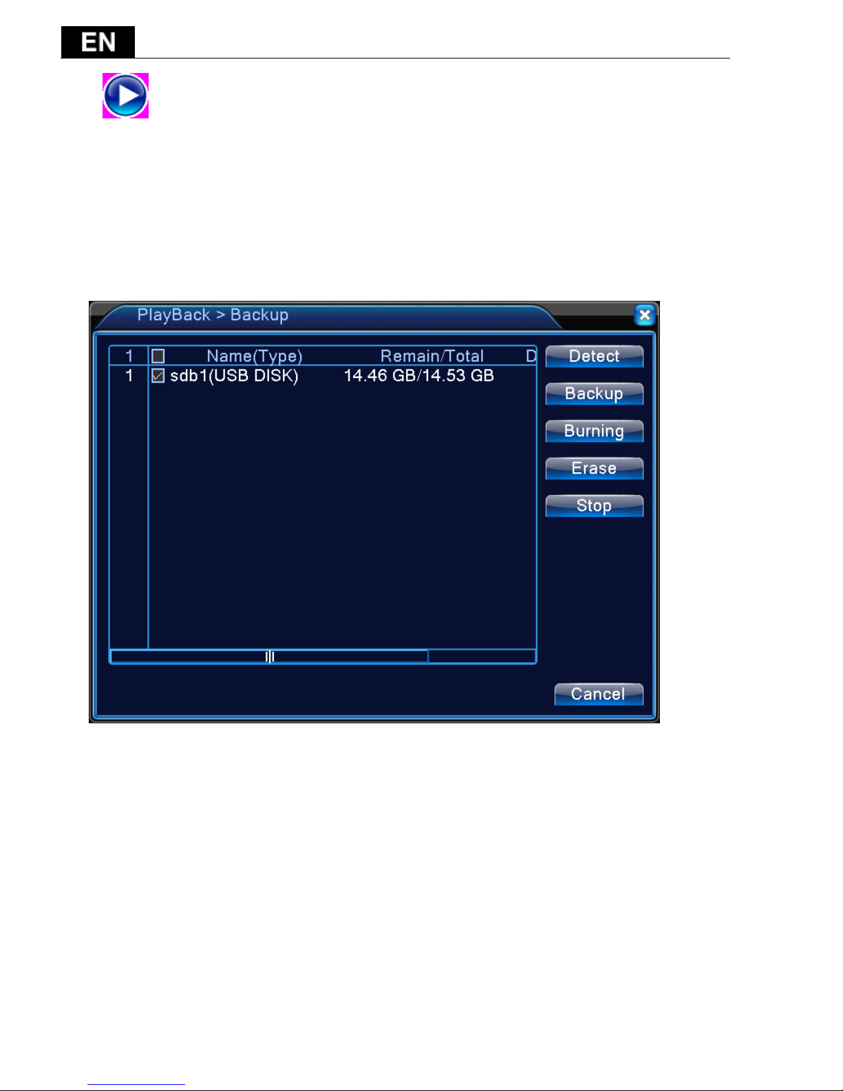
Note: The storage drive must be installed before the file can be backed-up.
If the backup is terminated any files already backed-up can be played-back
individually.
Picture 3.6 detect storage device
Detect: Detect the storage device connected to the DVR such as hard drive or
USB drive.
Erasure: Choose the file to delete and click erase to delete the file.
Stop: Stop the backup.
Backup: Click backup button and a dialog box will open. You can choose the
backup file according to the type, channel and time.
- 97 -
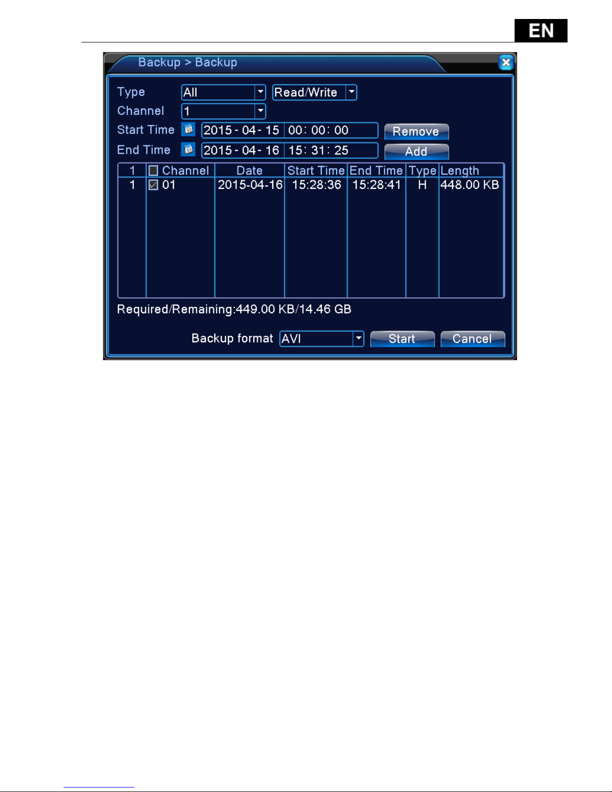
Picture 3.7 Recording backup
Remove:Clear file information.
Add:Show file information meeting the set file attributes.
Start/Pause:Click the play button to start the backup and click the pause
button to stop the backup.
Cancel: During backup you can exit the page layout to carry out other
functions.
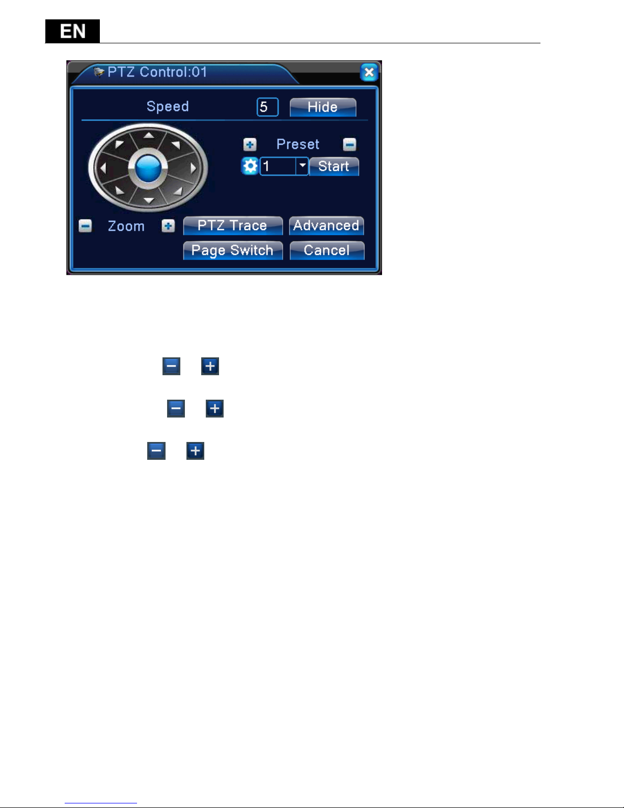
3.3.5 PTZ control
Operation interface is as followed. The functions include: PTZ direction
control, step, zoom, focus, iris, setup operation, patrol between spots, trail
patrol, boundary scan, assistant switch, light switch, level rotation and so on.
Note
1. Decoder A(B) line connects with DVR A(B)line. The connection is right.
2. Click [main menu] >[system configuration] >[PTZ setup] to set the PTZ
parameters.
3. The PTZ functions are decided by the PTZ protocols.
- 98 -
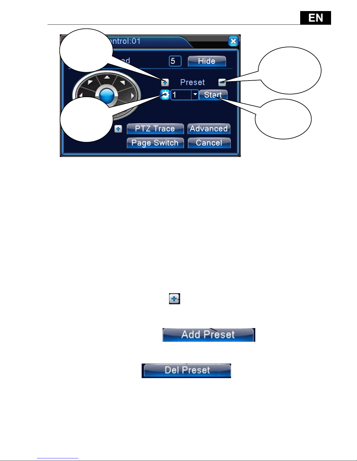
Picture 3.10 PTZ setup
【Speed】Set the PTZ rotation range. Default range: 1 ~ 8.
【Zoom】Click / button to adjust the zoom multiple of the camera.
【Preset】Click / button to add and delete preset.
【Iris】Click / button to adjust the iris of the camera.
【Hide】Current interface will be temporarily hidden after click it.
【 Direction control 】 Control the PTZ rotation. 8 directions control is
supportive.(4 directions in Front panel is supportive )
【Advance】Tour/pattern/focus/iris/autopan/autoscan.
【PTZ trace】move mouse to control PTZ.
【Page switch】Switch between different pages.
Special functions:
1. Preset
Set a location for the preset, calls the preset points, PTZ automatically
turns to the setting position
- 99 -
Picture 3.11 Preset Settings
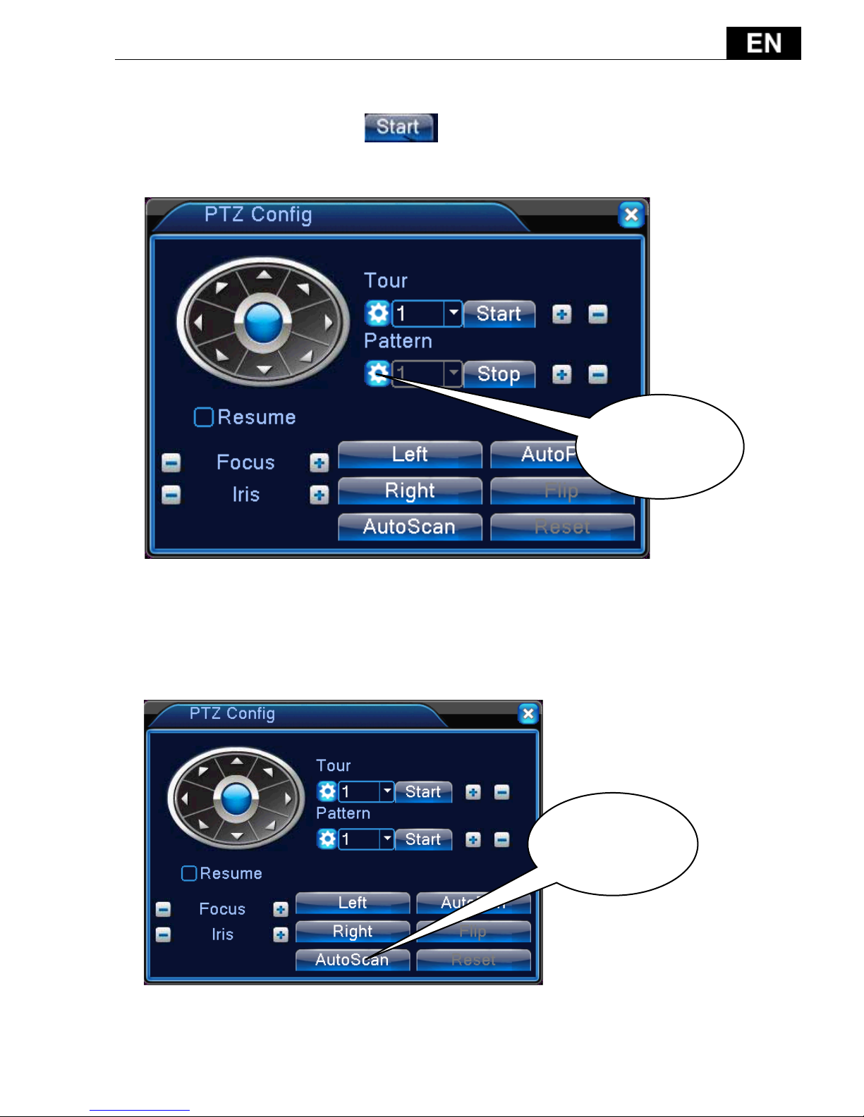
2. Tour between Points
Multiple preset points connected cruise lines, call cruise between points,
the PTZ run around on the line
1)Tour Between Points Settings
Tour lines is connected by multiple preset points, setting procedure is as
follows:
Step 1: In Picture 3.12, Click to add one tour, click Settings button to
enter Picture 3.13,
Step 2: In picture 3.13, click to add preset to this
tour, and set time.
Remove Preset:click
Add
preset
Delete
preset
Call
preset
Edit
preset

- 100 -
Picture 3.12 Tour Between Points
Picture 3.13 Tour Between Points Settings
Run one
tour
Tour
Setup
Add tour
Add
preset
Delete
preset
- 101 -
2)The Calls of tour between Points
Select tour number, click to call tour
Pattern
Picture 3.14 pattern
Set camera move as a pattern, not all camera support this function
Auto scan
Picture 3.15 Scan Setup
Call
autoscan
Setup
pattern
- 102 -
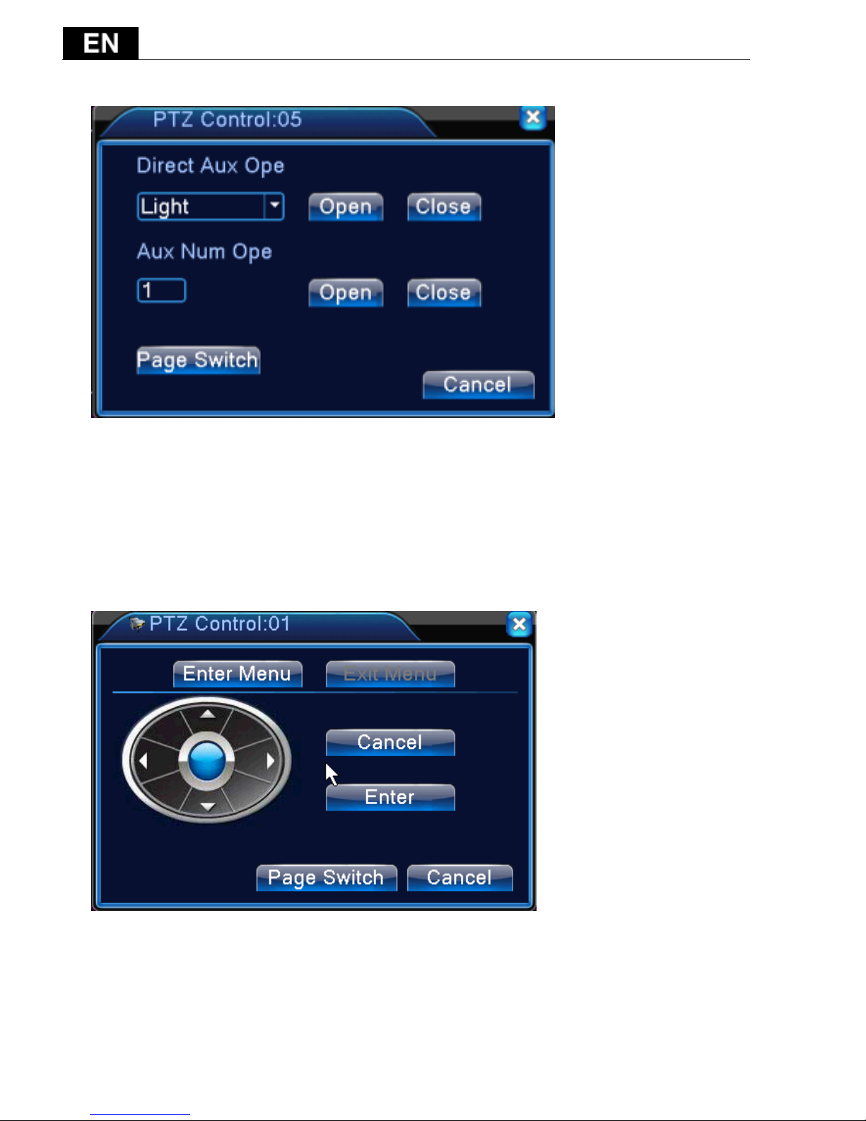
Other
Picture 3.16 Auxiliary Function Control
【Intuitive Auxiliary Operation】 choose auxiliary equipment, select Open or
Close button, switch control;
【 Auxiliary Number 】 The operation of corresponding auxiliary switch
according to PTZ agreement;
Picture 3.17 Camera menu Control
Enter cmaera menu, not all camera support.
- 103 -
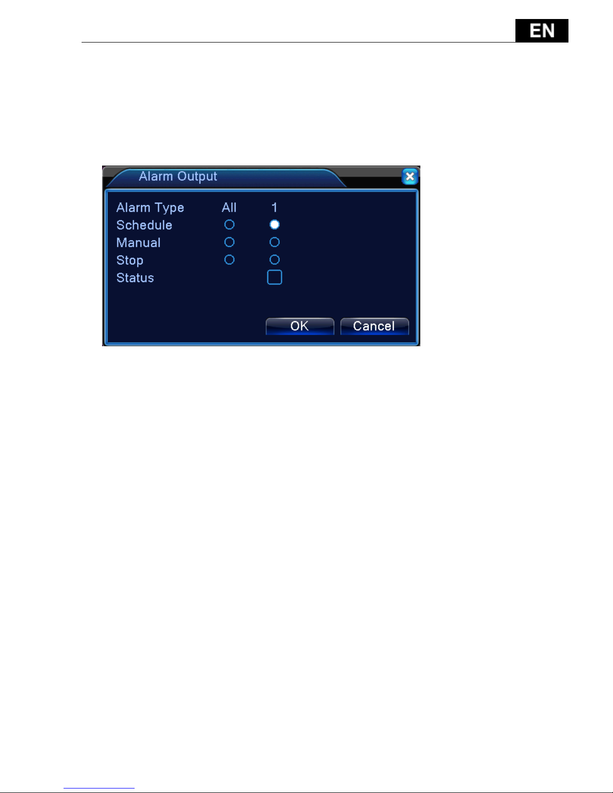
3.3.6 Alarm output
Please check current channel status: “○” means it is not in alarming status,
“●” means it is in alarming status.
You can use desktop shortcut menu or click [main menu]> [alarm function]>
[alarm output] to enter the alarm output interface.
Picture 3.9 alarm output
【Configuration】Alarm is on according to the configuration.
【Manual】Click the all button and the according channel is alarming no
matter the channel in any state.
【Stop】Click the stop button and the according channel stops alarming no
matter the channel in any state.
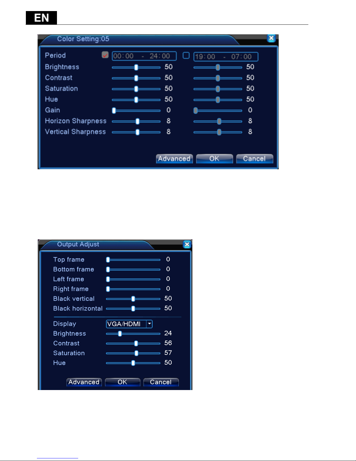
3.3.7 Color setting
Set the selective image parameters (current channel for single window display
and cursor place for multi-window display). You can use the desktop shortcut
menu and enter the interface. The image parameters include: tonality,
brightness, contrast, saturation. You can set different parameters at different
time sections.
- 104 -
Picture 3.18 Color Setting
3.3.8 Output Adjust
Adjust TV output area parameters. You can use the desktop shortcut menu or
enter [main menu]> [management tools]> [Output adjust].
Picture 3.19 Output Adjust
- 105 -
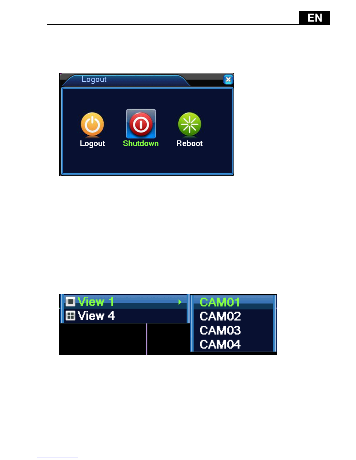
3.3.9 Logout
Logout, shut down the system or reboot up. You can use the desktop shortcut
menu or enter [main menu].
Picture 3.20 Logout/Shutdown/Reboot the system
【logout】Quit the menu. Offer password next entrance.
【shut down】Quit the system. Turn off the power supply.
When press the shut down button, there is schedule hint. After three seconds,
the system is shut down. Cancel midway is of no effect.
【reboot】Quit the system. Reboot up the system.
3.3.10 Window switch
Preview in single window/four windows.

- 106 -
4 Main menu
4.1 Main menu navigation
Main menu
Sub menu
Function
Record
Config
Set the recording configuration, recording
type, recording time section
playback
Set recording search, recording play, video file
storage
backup
Detect backup device, format device, back the
selective files
Alarm
Motion
detection
Set motion detect alarm channel, sensitivity,
area, linkage parameters: defending time
section, alarm output, screen hint, recording,
screen shot, PTZ, patrol, buzz, email and FTP
upload
Video
blind
Set camera mask alarm channel, sensitivity,
linkage parameters: defending time section,
alarm output, screen hint, recording, screen
shot , PTZ, patrol, buzz, email and FTP upload
Video
loss
Set video loss alarm channel, linkage
parameters: defending time section, alarm
output, screen hint, recording, screen shot ,
PTZ, patrol, buzz, email and FTP upload
Alarm
input
Set alarm input channel, equipment type,
linkage parameters: defending time section,
alarm output, screen hint, recording, screen
shot , PTZ, patrol, buzz, email and FTP upload
Alarm output
Set alarm mode: configuration, manual, shut
down
Abnormality
No disk, storage device error, disk no space,
net disconnection, IP conflicted

- 107 -
System
configuration
General
configuration
Set system time, data format, language, hard
disk full time operation, machine number,
video format, output mode, summertime, stay
time
Encode
configuration
Set main (extra) coding parameter: code
mode, resolving ability, frame rate, code
stream control, image quality type, code
stream value, frame between value,
video/audio enable,
Network
configuration
Set basic network parameters, DHCP and DNS
parameters, network high speed download
NetService
PPPOE、NTP、Email、IP purview、DDNS
parameter
GUI display
Set channel title, preview hint icon state,
transparency, cover area, time title, channel
title fold.
PTZ
configuration
Set channel, PTZ protocol, address, baud rate,
date bit, stop bit, check
PTZ Config
Set serial port function, baud rate, date bit,
stop bit, check
RS232
Set serial port function, baud rate, date bit,
stop bit, check
Tour
Set patrol mode and interval time
Digital
Set channel mode, check channel status and
configure the digital channel, etc.
Management
tools
Hard disk
management
Set appointed hard disk as read-write disc,
read-only disc or redundant disc, clear data,
resume date and so on
User
management
Modify user, team or password. Add user or
team. Delete user or team.

- 108 -
Online user
Break the connection with the already login
user. Lock the account after break until
booting up again.
Output adjust
Adjust upside, downside, nearside, starboard
distance, black margin vertical & horizontal
Automatic
maintenance
Set automatic reboot system and automatic
deleting files.
Restore
Resume setup state: common setup, code
setup, recording setup, alarm setup, network
setup, network service, preview playback,
serial port setup, user management
Upgrade
Upgrade with external device (like USB)
Device Info
Device hardware configuration and message
Import/
Export
Export the device's log or configuration to
external device(like USB flash disk);Input the
configuration with external device(like USB
flash disk).
System
information
Hard disk
information
Display hard disk capability and recording time
BPS
Display code stream information
Log
information
Clear all log information according to the log
video and time
Version
Display edition information
Shut down
Logout
Logout, shut down or reboot
4.2 Record
Operations related to record, including: Record, Playback, Backup
- 109 -
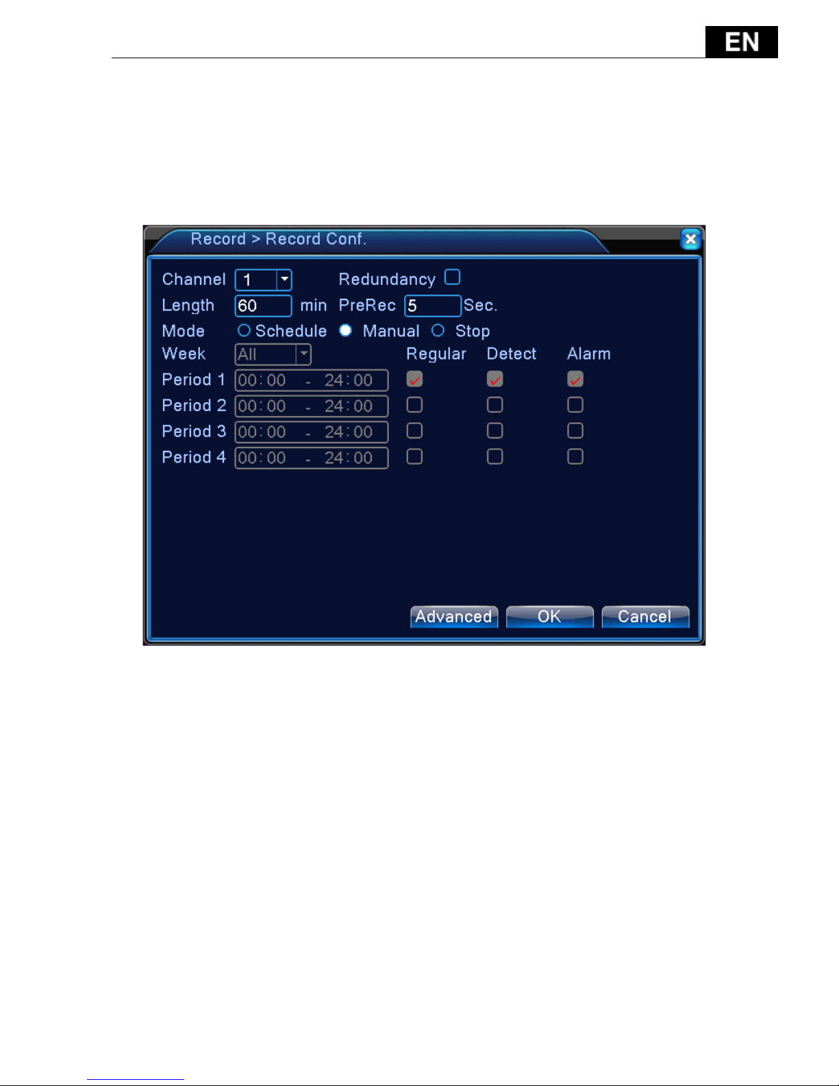
4.2.1 Record Configuration
Set the recording parameters in the surveillance channel. The system is set 24
hours consecutive recording in the first startup. You can enter [main menu]>
[recording function]> [recording setup] to set.
Note: There is at least one read-write hard disk.
Picture 4.1 Record Configuration
【Channel】Choose the corresponding channel number to set the channel.
Choose the all option to set the entire channels.
【Redundancy】Choose the redundancy function option to implement the file
double backup function. Double backup is writing the video files in two hard
disks. When you do the double backup, make sure that there are two hard disks
installed. One is read-write disk and the other is redundant disk.
【Length】Set the time length of each video file. 60minutes is default value.
【Pre-Record】Record 1-30 seconds before the action. (time length is decided
by the code stream)
【Record mode】Set video state: schedule, manual or stop.
Schedule:Record according to the set video type (common, detection and

- 110 -
alarm)and time section.
Manual:Click the button and the according channel is recording no matter the
channel in any state.
Stop:Click the stop button and the according channel stops recording no
matter the channel in any state.
【Period】Set the time section of common recording, The recording will start
only in the set range.
【Record type】Set recording type: regular, detection or alarm.
Regular: Perform the regular recording in the set time section. The video file
type is “R”.
Detect: Trigger the “motion detect”, “camera mask” or “video loss” signal.
When above alarm is set as opening recording, the “detection recording” state is
on. The video file type is “M”.
Alarm:Trigger the external alarm signal in the set time section. When above
alarm is set as opening recording, the “detection recording” state is on. The
video file type is “A”.
4.2.2 Playback
Refer to chapter 3.3.4.
4.2.3 Backup
Refer to chapter 3.3.4
4.3 Alarm Function
Alarm functions include: motion detect, video blind, video loss, alarm input
and alarm output, abnormality.
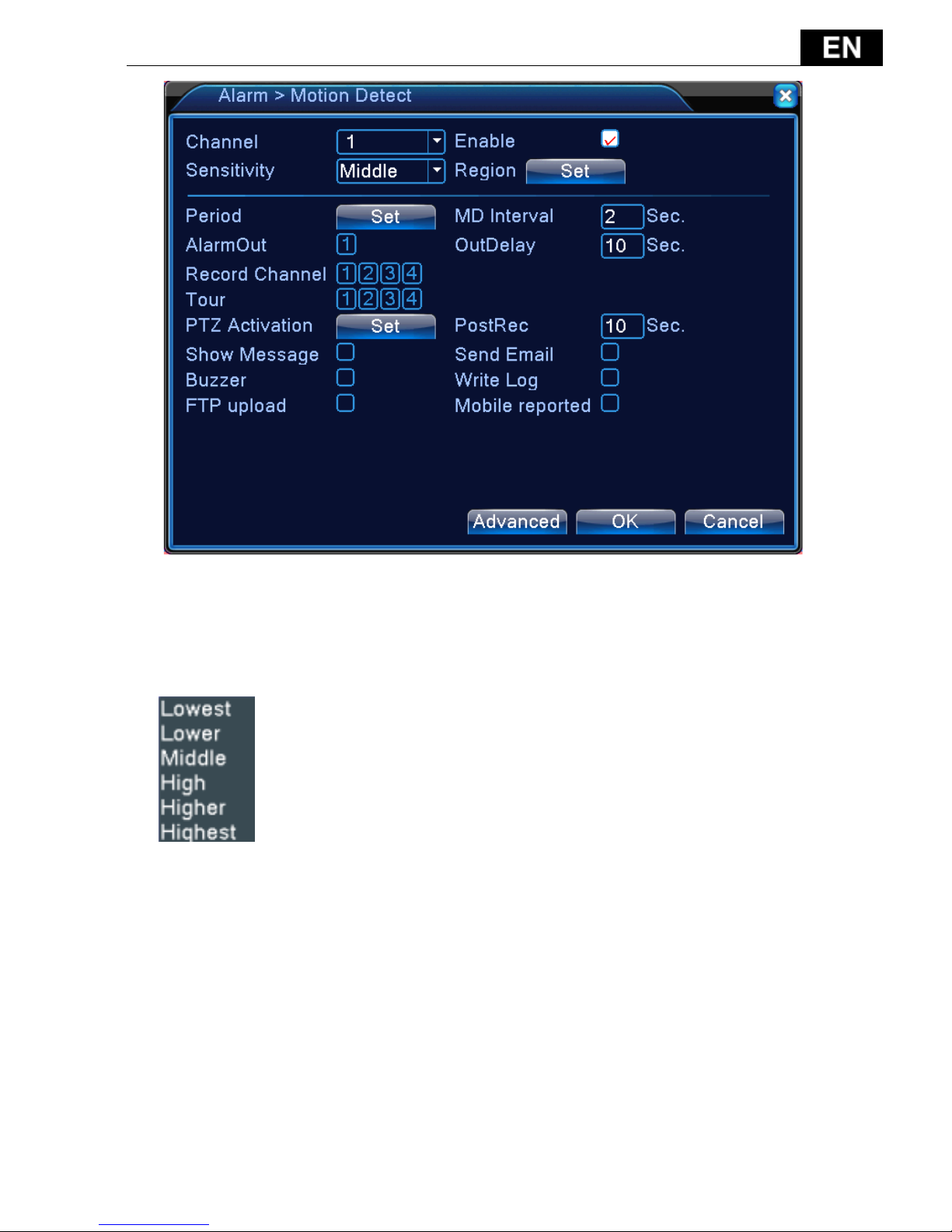
4.3.1 Motion Detect
When system detects the motion signal that reaches the set sensitivity, the
motion detect alarm is on and the linkage function is turned on.
Note: "Advanced" button is the same as right click.
- 111 -
Pic 4.4
【Channel】Choose the set motion detect channel.
【Sensitivity】Choose in the six options according to the sensitivity.
.
【Region】Click [set] to enter the set area. Red block means the motion detect
defensive area. White block means the unfenced area. You can set the area as
followed, Drag the mouse and draw the area. Default: all selected blocks are
detection area.

- 112 -
Picture 4.5 Region
【Period】Trigger the motion detect signal in the set time section. You can set
according to week or set uniformly. Each day is divided into four time sections.■
means the set valid.
Picture 4.6 set the time section
【Interval】Only one alarm signal is turned on even there are several motion
detect signals in the set interval.
【Alarm output】Start the external equipment of corresponding linkage alarm
when the motion detect alarm is turned on.
【Delay】Delay a few moments and stop when the alarm state is turned off.
- 113 -
The range is 10~300 seconds.
【Record channel】Choose the recording channel (multiple option supportive).
Trigger the video signal when the alarm is turned on.
Note: Set in the [recording setup] and perform the linkage recording. Start
detecting video files in the corresponding time section.
【Tour】■ means that the selective channel is single window alternate patrol
preview. The interval is set in the [Main Menu]>[System] > [Tour].
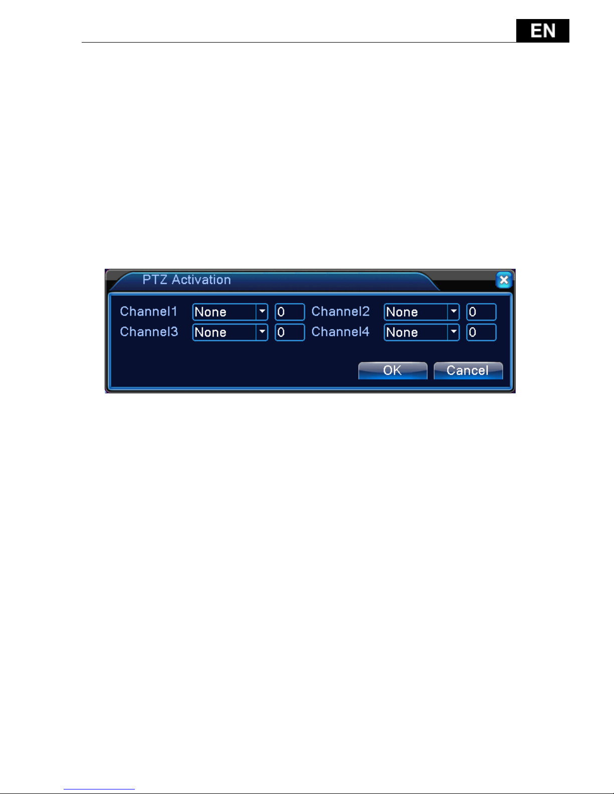
【PTZ Activation】Set the PTZ activation when the alarm is turned on.
Note:to link PTZ, need go [Shortcut menu]->[PTZ control] to set preset
point, cruise between points & interval time, etc.
Picture 4.7 PTZ Activation under hybrid mode
【Delay】When alarm is over,recording will last some seconds(10~300sec),then
stop.
【Show message】Pop the alarm information dialog box in the local host
computer screen.
【Send EMAIL】■ means sending an email to user when the alarm is turned on.
Note:Set in the [NetService] and send email.
【Buzzer】When alarm happens, device will come out with buzz.
【Write log】write alarm information to log.
【FTP upload】to tick it, the video & picture of related record channel &
snapshot channel will be uploaded to assigned position.
Note:FTP upload need be set at [Netservice]
【Mobile reported】push alarm message to mobile phone

- 114 -
4.3.2 Video Blind
When the video image is influenced by the environment such as bad brightness
or reaching the set sensitivity parameter, the camera mask function is turned on
and the linkage function is turned on.
Pic 4.8 Video blind
Set method: refer to chapter 4.3.1. Motion detect
4.3.3 Video Loss
When the equipment can not obtain the channel video signal, the video loss
alarm is turned on and the linkage function is turned on.

- 115 -
Pic 4.9 Video loss
Set method: refer to chapter 4.3.1. Motion detect
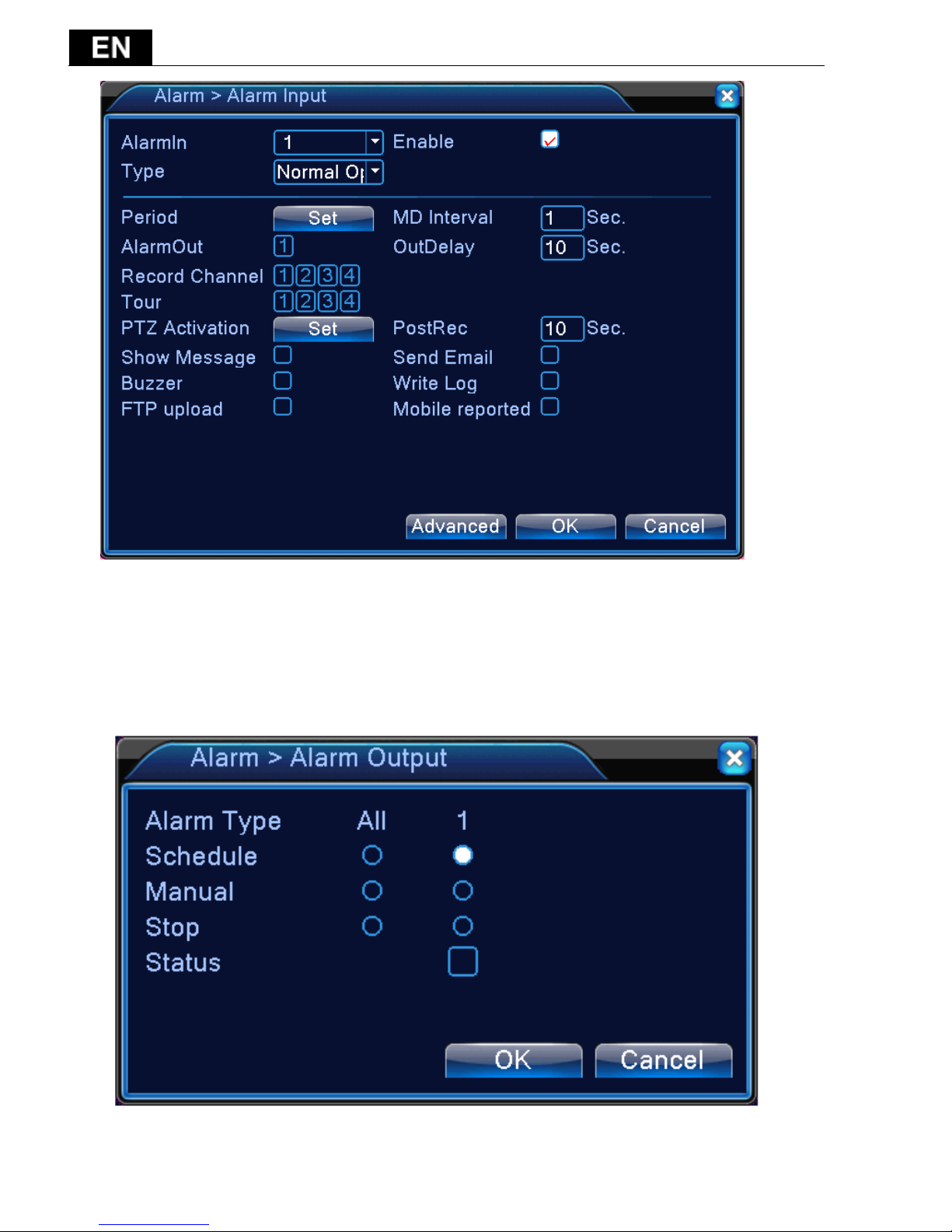
4.3.4 Alarm input
When the equipment obtains the external alarm signal, the alarm function is
turned on.
Note: "Advanced" button is the same as right click.
- 116 -
Pic 4.10 Alarm input
Set method: refer to chapter 4.3.1. Motion detect
4.3.5 Alarm output
- 117 -
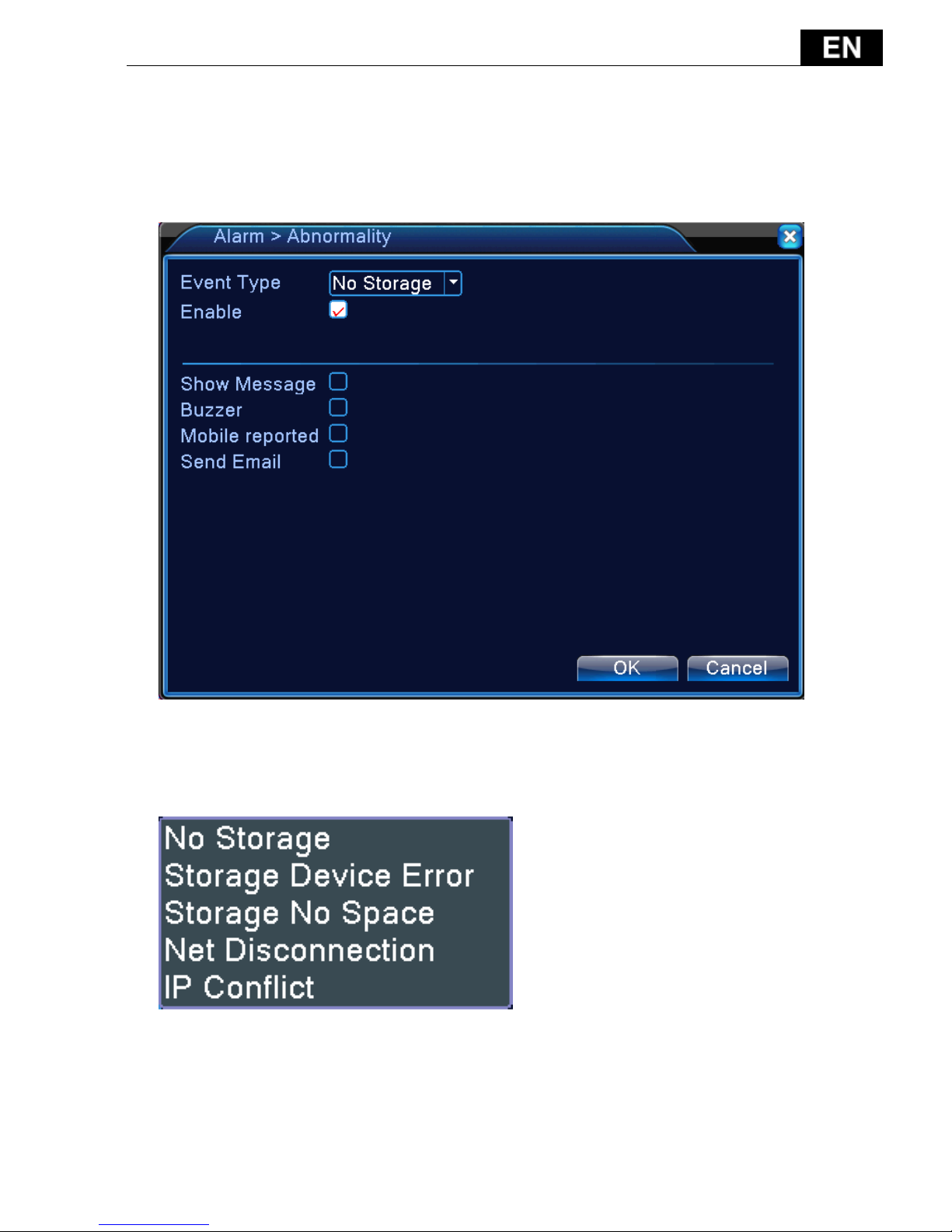
4.3.6 Abnormality
Analysing and inspecting current software and hardware of the device:
When some abnormal events happen, the device will make a relative answer such
as show message and buzzer.
Picture 4.11 Abnormal
【Event Type】selecting abnormity you want to inspect
【Enable】Select it to make sure abnormal function workable
【Show message】Automatically alarm cue dialog box come out of the main
screen
【Buzzer】Device will have one long noise “di” while alarm is happening
- 118 -
【Mobile reported】push alarm message to mobile phone
【Send email】 send alarm email
4.4 System setup
Set the system parameters such as General, Encode, Network, Net service,
Display, PTZ configure, RS232, Tour setup, Digital.
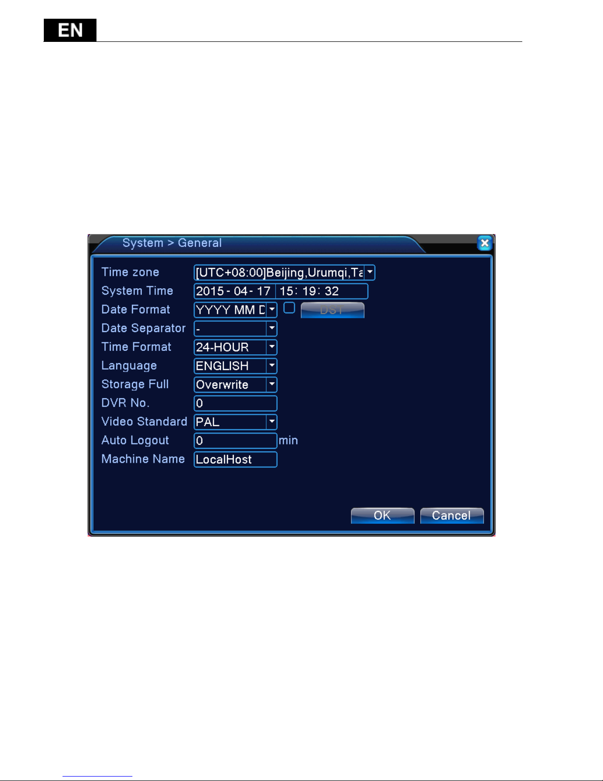
4.4.1 General
Picture 4.17 General setup
【System time】Set the system data and time.
【Date format】Choose the data format: YMD, MDY, DMY.
【Date Separator】Choose list separator of the data format.
【Time Format】Choose time format: 24-hour or 12-hour.
【Language】Support multiple language
【Storage full】Choose stop record: Stop recording when the hard disk is full.
Choose overwrite: Cover the earliest recording files and continue
recording when the hard disk is full.
【DVR No.】Only when the address button in the remote controller and the

- 119 -
corresponding DVR number is matched, the remote operation is valid.
【Video Standard】PAL or NTSC.
【Auto Logout】Set the latency time in 0-60. 0 means no latency time.
【Machine Name】Can setting the device's name.
【DST】Choose the summer time option and pop the dialog box as followed.
Picture 4.18 DST (week)
Picture 4.19 DST (date)
4.4.2 Encode setup
Set the video/audio code parameter: video file, remote monitoring and so on.
Set every main stream parameter in the left part, and set the extra stream
parameter in the right part.
Note: extra stream introduces video compression technique which was
applying for multi-channel playback simultaneously, Dial-up multi-channel
real-time monitor under poor bandwidth, or mobile monitor and so on.

- 120 -
Picture 4.20 Encode setup
Independent channel code setting
【Channel】Choose the channel number.
【Compression】Standard H.264 main profile.
【Resolution】Video resolution.
【Frame Rate】P:1 frame/s~25 frame/s; N: 1 frame/s~30 frame/s
【Bit Rate Type】You can choose limited code stream or variable code stream.
When you choose the variable code stream there are six image quality options.
under the limited code stream,you can choose the code stream manually;
【Bit Rate】Set the code stream value to modify the image quality. The larger
code stream value the better image quality.
【Frame Interval】can choose the range 2~12s
【Video/Audio】When the icons are all in reverse displayed, the video file is
video and audio multiplex stream.
Extra stream Settings
【Extra stream】is used for client side monitoring & mobile monitoring.
【Channel title】select channel title and then to choose whether need

- 121 -
enable video & audio. The resolution, frame rate, bit rate type settings is the
same as main stream.
4.4.3 Network setup
Picture4.21 Network
【DHCP Enable】Obtain IP address automatically(not suggested)
【IP address】Set the IP address. Default: 192.168.1.10.
【Subnet mask】Set the subnet mask code. Default: 255.255.255.0.
【Gateway】Set the default gateway. Default: 192.168.1.1.
【DNS setup】Domain Name Server. It translates the domain name into IP
address. The IP address is offered by network provider. The address must be set
and reboot then it works.
【Media port】Default: 34567.
【HTTP port】Default: 80.
【HS Download】high speed download file
【Transfer Policy】There are three strategies: self-adaption, image quality
precedence and fluency precedence. The code stream will adjust according to
the setup. Self-adaption is the tradeoff between the image quality precedence

- 122 -
and fluency precedence. Fluency precedence and self-adaption are valid only
when the assistant code stream is turned on. Otherwise image quality
precedence is valid.
4.4.4 NetService
Choose the network service option and click the set button to configure the
advanced network functions or double click the service button to configure the
parameters.
Picture 4.22 NetService
【PPPoE setup】
- 123 -
Picture 4.23 PPPOE
Enable:Reverse means choose, setting can become effective.
Input the user name and password that ISP( Internet service provider)
provides. After saving it reboot up your system. Then the DVR will build a
network connection based on PPPoE. The IP address will change into dynamic IP
address after above operation is well done.
Operation:After PPPoE dialing successfully look up the IP address in the [IP
address] and obtain the current IP address. Then use this IP address to visit the
DVR through user port.
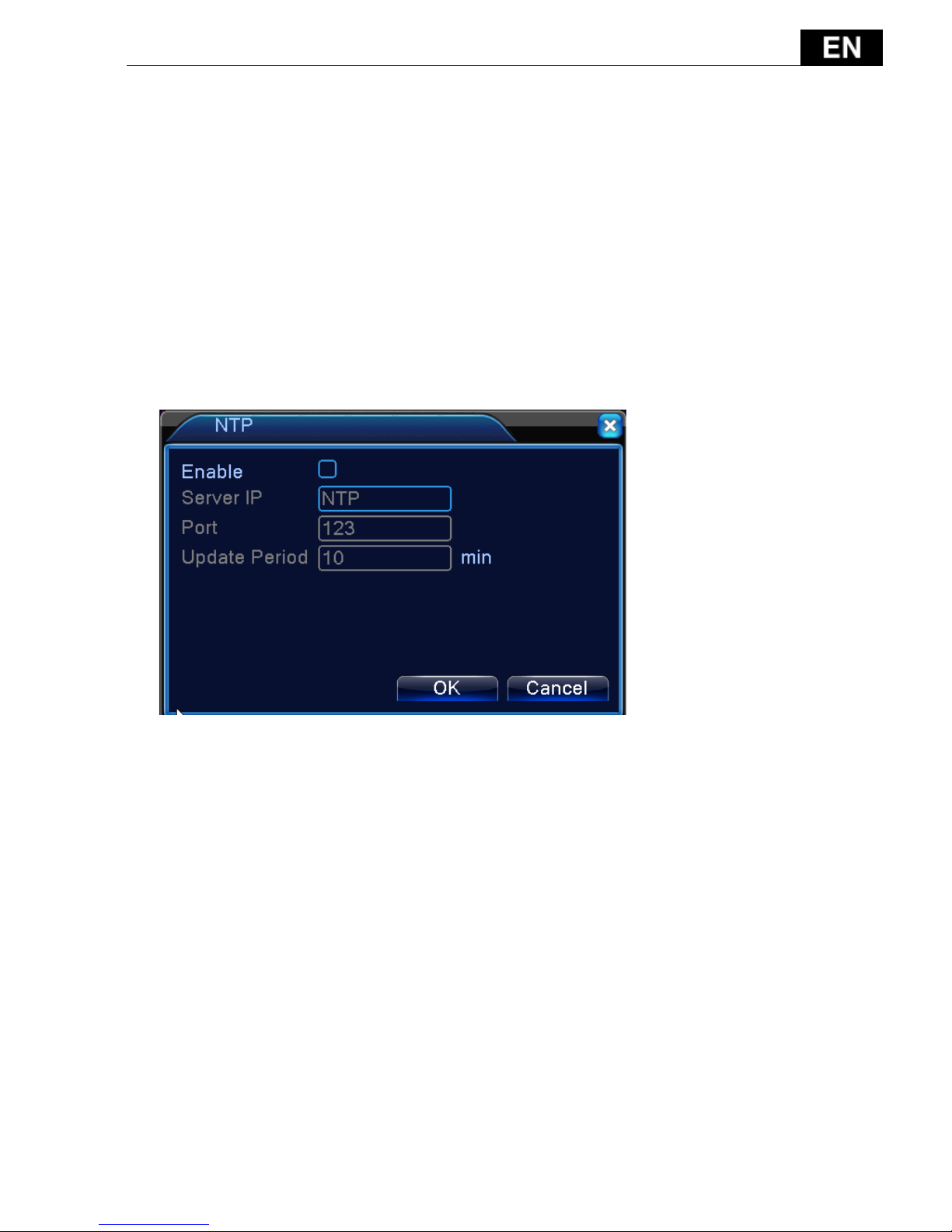
【NTP setup】
Picture 4.24 NTP
The NTP server must be installed in the PC.
Host computer IP: Input the IP address installed NTP server.
Port: Default: 123. You can set the port according to NTP server.
Time zone: London GMT+0 Berlin GMT +1 Cairo GMT +2 Moscow GMT +3
New Delhi GMT +5 Bangkok GMT +7 Hongkong Beijing GMT +8 Tokyo GMT +9
Sydney GMT +10 Hawaii GMT-10 Alaska GMT-9 Pacific time GMT-8
American mountain time GMT-7 American mid time GMT-6 American eastern
time GMT-5 Atlantic time GMT-4 Brazil GMT-3 Atlantic mid time GMT-2.
Update Period: The same with the NTP server check interval. Default:
10minutes.
【EMAIL setup】

- 124 -
If the alarm is turned on or the alarm linkage photos are taken, send an email
about the alarm information and the photos to appointed address.
Picture 4.25 EMAIL
SMTP server: Email server address. It could be an IP address or domain name.
Domain name can be translated only it is the correct DNS configuration.
Port :Email server port number.
SSL: Using Secure Socket Layer protocol to login.
User Name: Apply the email server user name.
Password: Input the password corresponding to the user.
Sender: Set the email sender address.
Receiver: Send the email to appointed receivers when the alarm is turned on.
You can set three receivers at most.
Title: Email title.
【IP Filter setup】
When choosing the white list, only the listed IP address can connect the DVR.
The 64 IP addressed are supportive in the list.
When choosing the black list, the listed IP address can not connect the DVR.
The 64 IP addressed are supportive in the list.
You can delete the set IP address by √ in the options.
Note:When the same IP address is in the white and black list at the same

- 125 -
time, the black list precedence is higher.
Picture 4.26 IP FILTER
【DDNS】
Picture 4.27 DDNS setup
It is the abbreviation of dynamic domain name server.
Local domain name:Provide the domain name registered by DDNS.
User name:Provide the account registered by DDNS.
Password:Provide the password registered by DDNS.
【FTP setup】

- 126 -
FTP is available only when alarm happens, or alarm activates record and
snapshot, it will upload related record and snapshot pictures to FTP server.
Picture 4.28 FTP setup
【Enable】Click Enable, then all settings will be available
【Server IP】IP address for FTP server
【Port】Domain Port of FTP, default 21
【User Name】User name of FTP
【Password】Password of user
【Anonymous】:enable anonymous, no need setting user name and password
【Max File Length】Max length for upload files at every packed, default 128M
【Dir Name】:The directory of upload file.
【UPNP】
UPNP protocol is to realize auto port forwarding on router, precondition of
using this function is to make sure the UPNP function of router is enabled.

- 127 -
Picture 4.33 UPNP
【Enable】Choose Enable to make sure all UPNP settings available
【HTTP】Route will automatically distribute HTTP port for the device, when IE
viewing, it need this port
【TCP】Router will automatically distribute TCP port for the device, when
monitoring via CMS, it need this port.
【Mobile Port】Router will automatically distribute Mobile Port for the device.
【RTSP】
To do surveillance via cross-browser (Safari, Firefox, Google chrome) and VLC
software. This function only for monitor but can not control the device.

- 128 -
Pic 4.35 RTSP setting
【Port】:the default port is 554
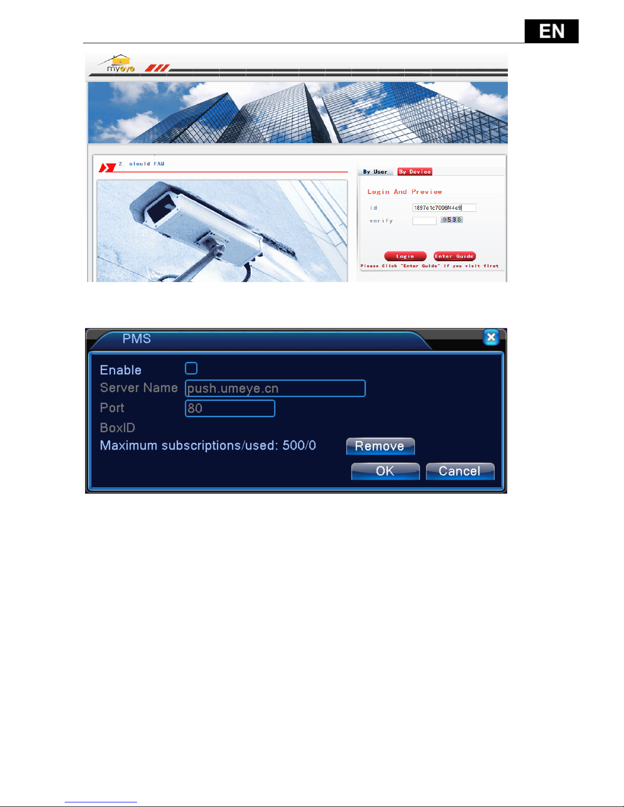
【Cloud】
【Enable】The user can enter http://xmeye.net to login device by serial
number.
Pic 4.29 cloud
Enable this function, When you want to visit the DVR on internet, needn’t
manually map port in router.
- 129 -
【PMS】
When DVR get alarm, DVR send alarm message to mobile.
4.4.5 Display
Configure the video output parameters including the front output mode and
encode output mode.
Front output:In the local preview mode include: channel title, time display,
channel display, record status, alarm status, transparency and region cover.
Encode output:In the network surveillance and video file mode include:
channel title, time display, channel display, record status, alarm status,
transparency and region cover.

- 130 -
Pic 4.36 output mode
【Channel Title】Click the channel name modify button and enter the channel
name menu. Modify the channel name. The 16 Chinese characters and 25 letters
are supportive.
【Time Display】means the selective state. Display the system data and time
in the surveillance window.
【Channel display】means the selective state. Display the system channel
number in the surveillance window.
【Record Status】means the selective state. Display the system recording
status in the surveillance window.
【Alarm Status】means the selective state. Display the system alarm status in
the surveillance window.
【Transparency】Choose the background image transparency. The range is
128~255.
【Resolution】set display resolution.
【Channel】Choose the set code output channel number.
【Region Cover】means the selective state. Click the cover area button and
- 131 -
enter the corresponding channel window. You can cover the arbitrary using
mouse. (Black region is for output)
【Time display】and 【Channel display】 set the display position of channel
title and time title.
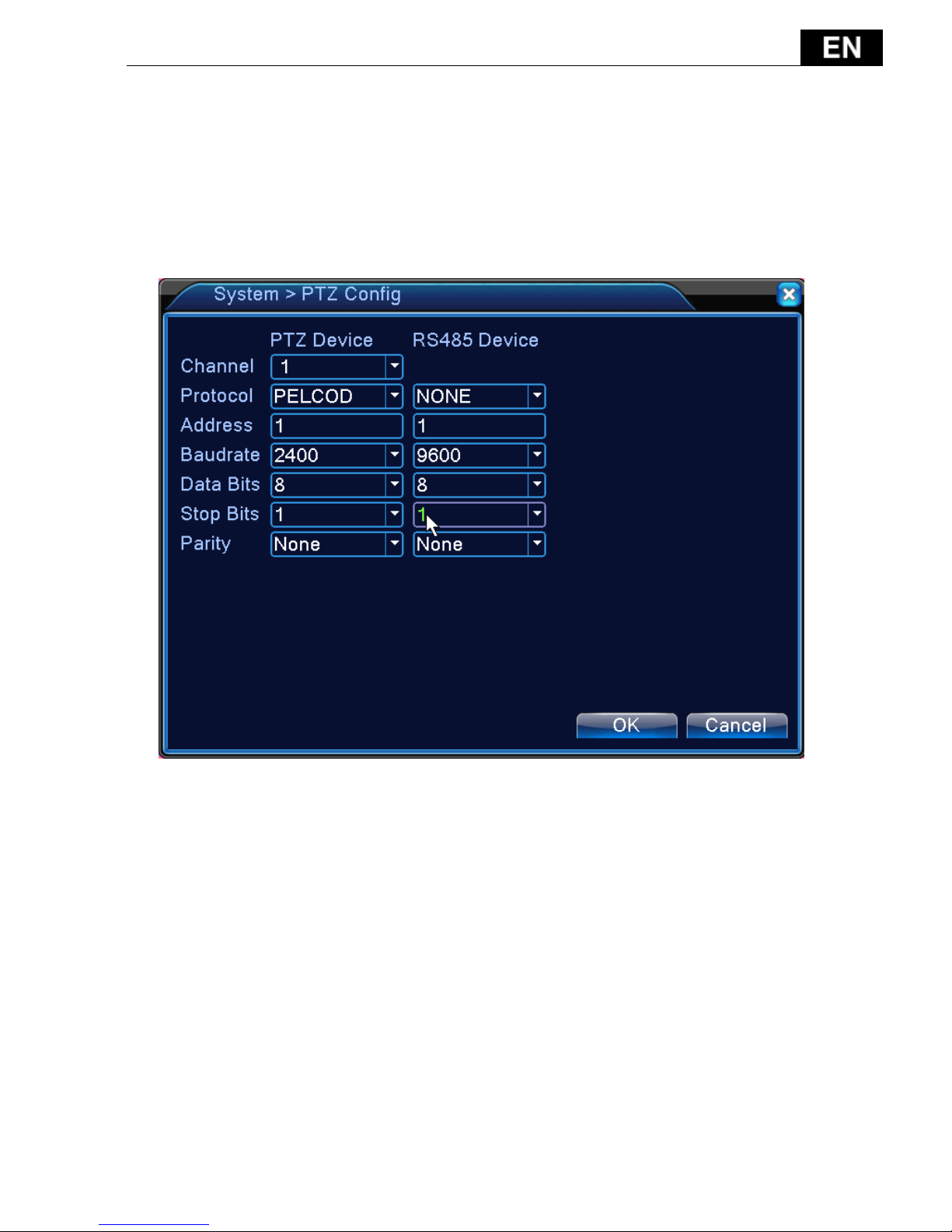
4.4.6 PTZ config
Pic 4.37 PTZ configure
【Channel】Choose the dome camera input channel.
【Protocol】Choose the corresponding dome protocol. (PELCOD as an example)
【Address】Set as the corresponding dome address. Default: 1.(Note:The
address must be consistent with the dome address.)
【Baudrate】Choose the corresponding dome baud rate length.
【Data bits】Include 5-8 options. Default: 8.
【Stop bits】Include 2 options. Default: 1.
【Parity】Include odd check, even check, sign check, blank check. Default:
void.

- 132 -
4.4.7 RS232
Pic 4.39 serial port setting
【Serial Port Function】Common serial port is used to debug and update
program or set up specific serial port.
【Baud rate】Choose the corresponding baud rate length.
【Data bits】Include 5-8 options.
【Stop bits】Include 2 options.
【Parity】Include odd, even, mark, space, default is none.
4.4.8 Tour
Set the patrol display. You can choose 1/4 channel view.

- 133 -
Pic 4.40 tour configure
【MD interval】Set the patrol switch interval. The set range is 5-120 seconds.
【Return after finished】After alarm, back to tour.
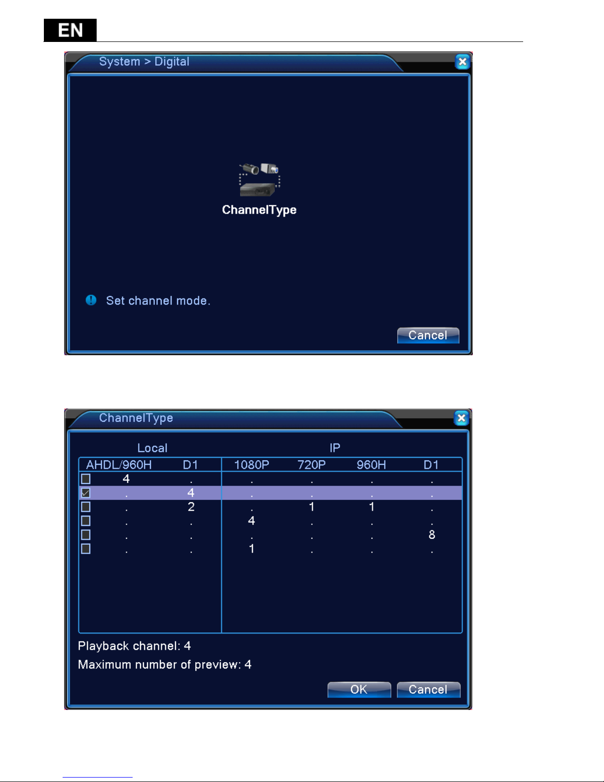
4.4.9 Digital
Digital manage including digital channel, channel status, and channel mode
- 134 -
Pic 4.42 channel manage interface
Channel mode:

- 135 -
4.5 Advanced
Manage tools menu including: HDD manage, account manage, online user,
output adjust, auto maintain, upgrade.
4.5.1 HDD Manage
Configure and manage the hard disk. The menu displays current hard disk
information: hard disk number, input port, type, status and overall capability.
The operation include: setup the write-read disk, read-only disk, redundant disk,
hard disk format, resume default. Choose the hard disk and click the right
function button to execute.
Note:Read/Write Disk: The equipment can write or read data.
Read-only Disk: The equipment can read data but can not write data.
Pic 4.46 HDD manage
4.5.2 Account
Manage the user purview.
Note:1. The character length is 8 bytes at most for the following user and
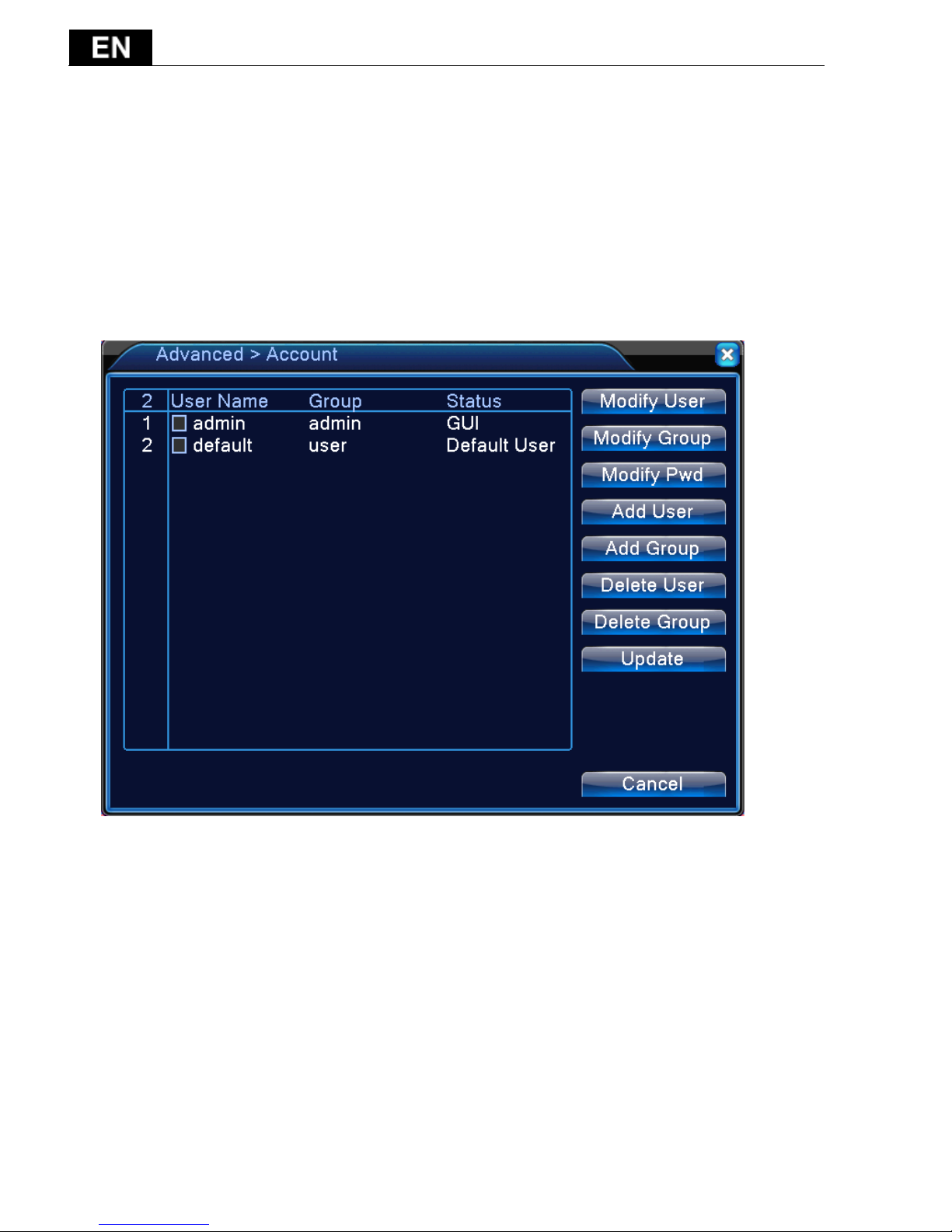
- 136 -
user team name. The blank ahead or behind the character string is invalid. The
middle blank in the character string is valid. Legal characters include: letter,
number, underline, subtraction sign, dot.
2. There is no limit in the user and user group. You can add or delete the user
group according to user definition. The factory setup include: user\admin. You
can set the team as you wish. The user can appoint the purview in the group.
3. The user management include: group/ user. The group and user name can
not be the same. Each user only belongs to one group.
Pic 4.47 account management
【Modify User】Modify the existed user attribute.
【Modify Group】Modify the existed team attribute.
【Modify Password】Modify the user password. You can set 1-6 bit password.
The blank ahead or behind the char string is invalid. The middle blank in the char
string is valid.
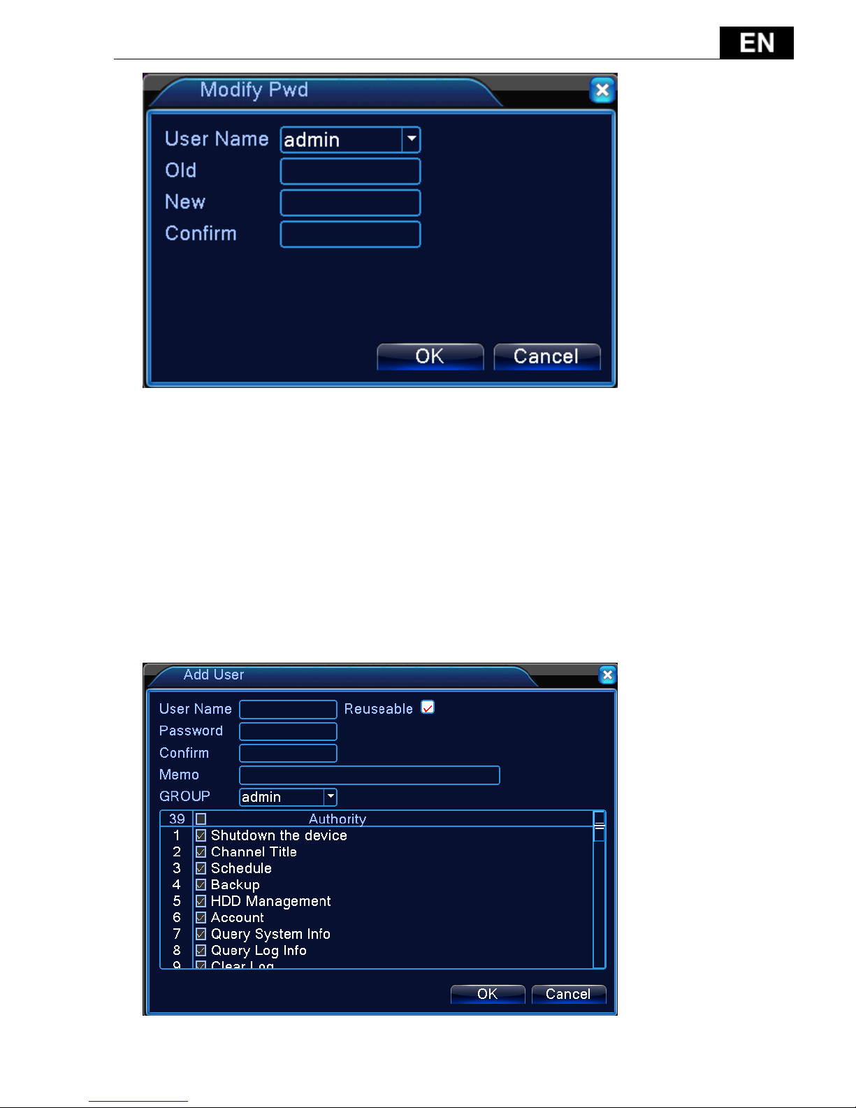
- 137 -
Pic 4.48 modify password
【Add user】Add a user in the group and set the user purview. Enter the menu
interface and input the user name and password. Choose the team and choose
whether cover using the user. Cover using means that the account can be used by
multiple users at the same time.
Once choose the team the user purview is the subclass of the team.
We recommend that the common user’s purview is lower than the advanced
user.
- 138 -
Pic 4.49 Add User
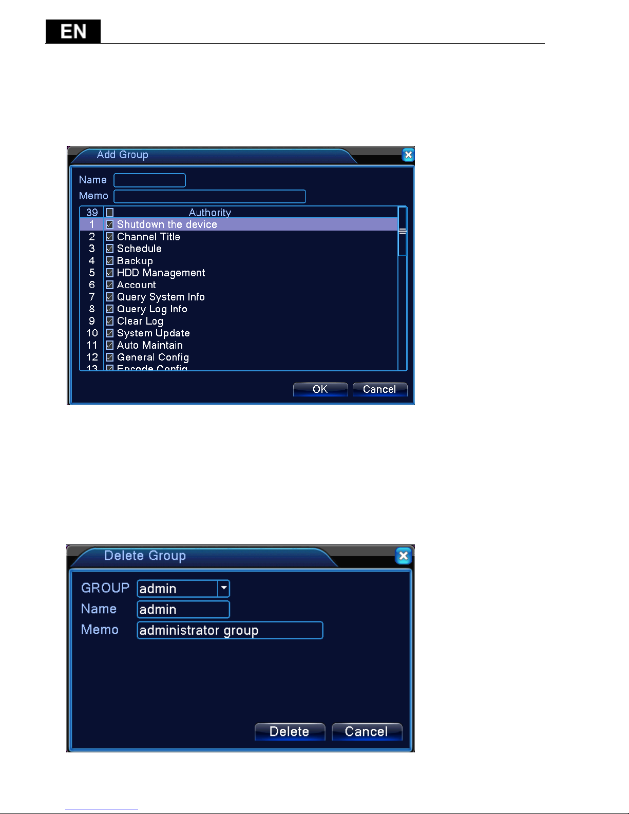
【Add Group】Add a user group and set the purview. There are 33 different
purviews: shut down the equipment, real time surveillance, playback, record
setting, video backup and so on.
Pic 4.50 add group
【Delete User】Delete the current user. Choose the user and click delete user
button.
【Delete Group】Delete the current group. Choose the group and click delete
group button.
- 139 -
Pic 4.51 Delete Group
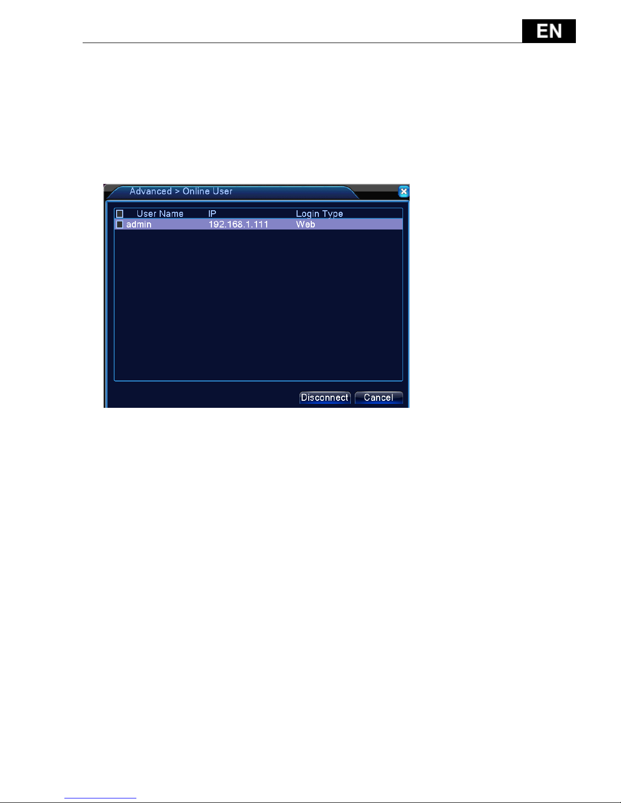
4.5.3 Online user
To check the information of network user that connected with local device,
also can tick the selected user to break up connection, then the user will be
frozen after connection stopped, and will not log in until device reboot.
Pic 4.52 online user

- 140 -
4.5.4 TV adjust
4.5.5 Auto Maintain
The user can set the time to auto reboot and auto delete file.
Picture 4.39 Auto maintain
4.5.6 Restore
The system restore to the default . You can choose the items according to the
menu.

- 141 -
Pic 4.54 restore to default
4.5.7 Upgrade
Pic 4.55 Upgrade
【Upgrade】choose USB interface.
【Upgrade file】choose the upgrade file.
- 142 -
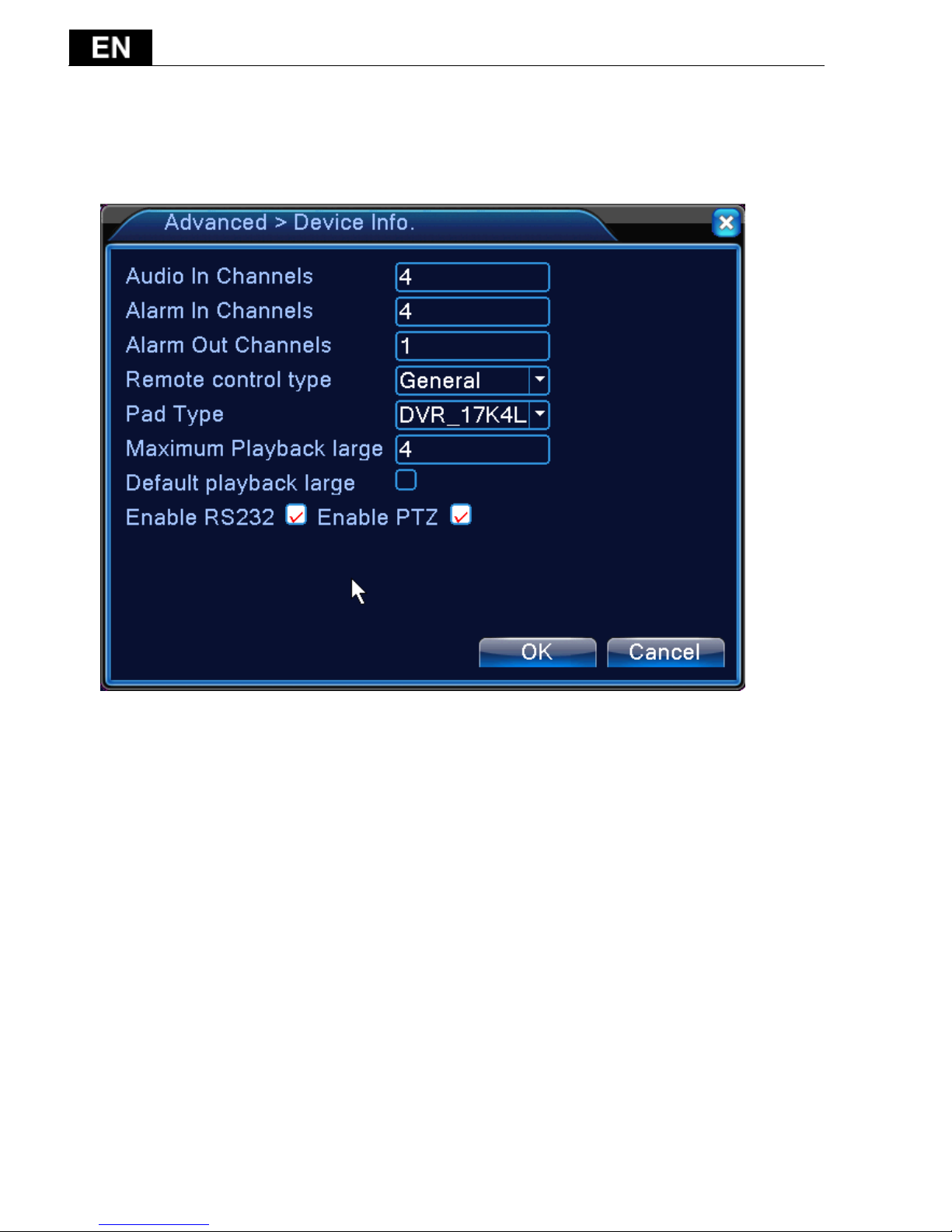
4.5.8 Device Info
Provide device interface info like audio in, alarm in/out to be conveniently
used for user.
Pic 4.56 device info
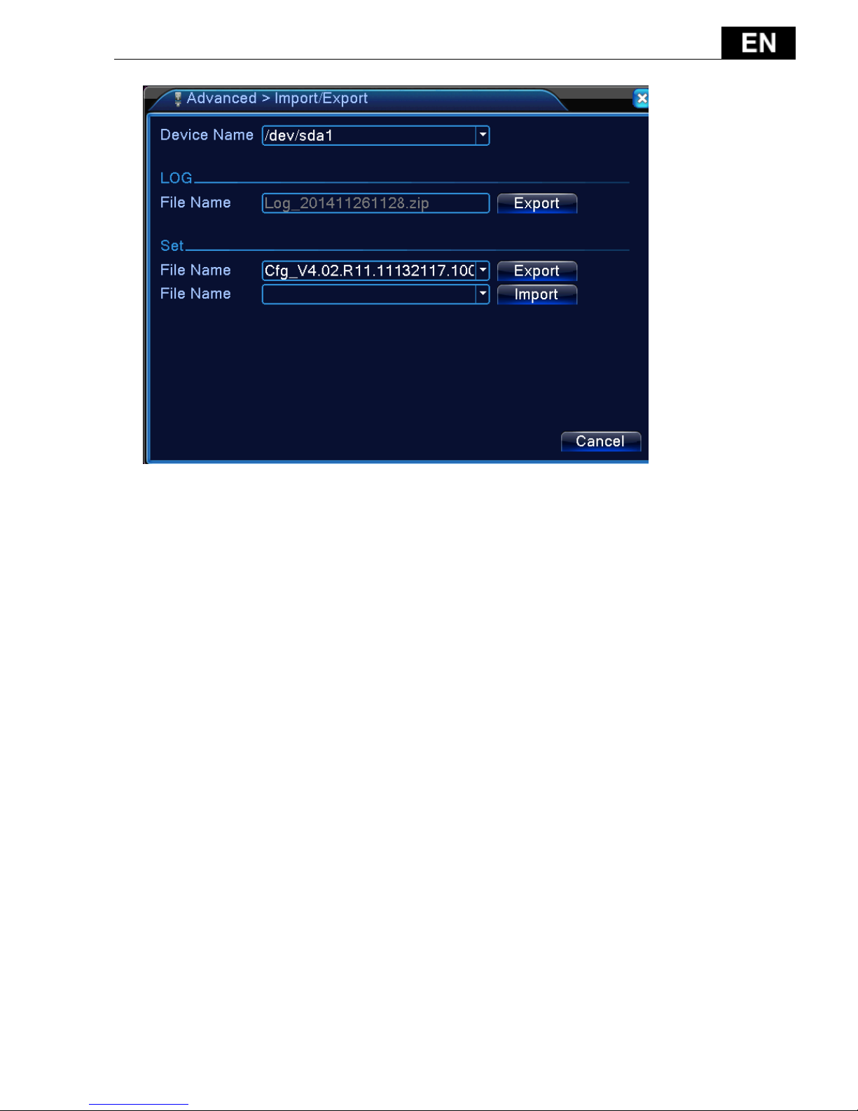
4.5.9 Import / Export
Users can export the log info and the configure file from device to connected
flash stick, and also can import related configure file from flash stick to settings,
which greatly bring convenience to the customers.
- 143 -
4.57 Import / Export interface
4.6 Info
Display the hard disk information, including HDD info, code stream statistic,
log info, version info
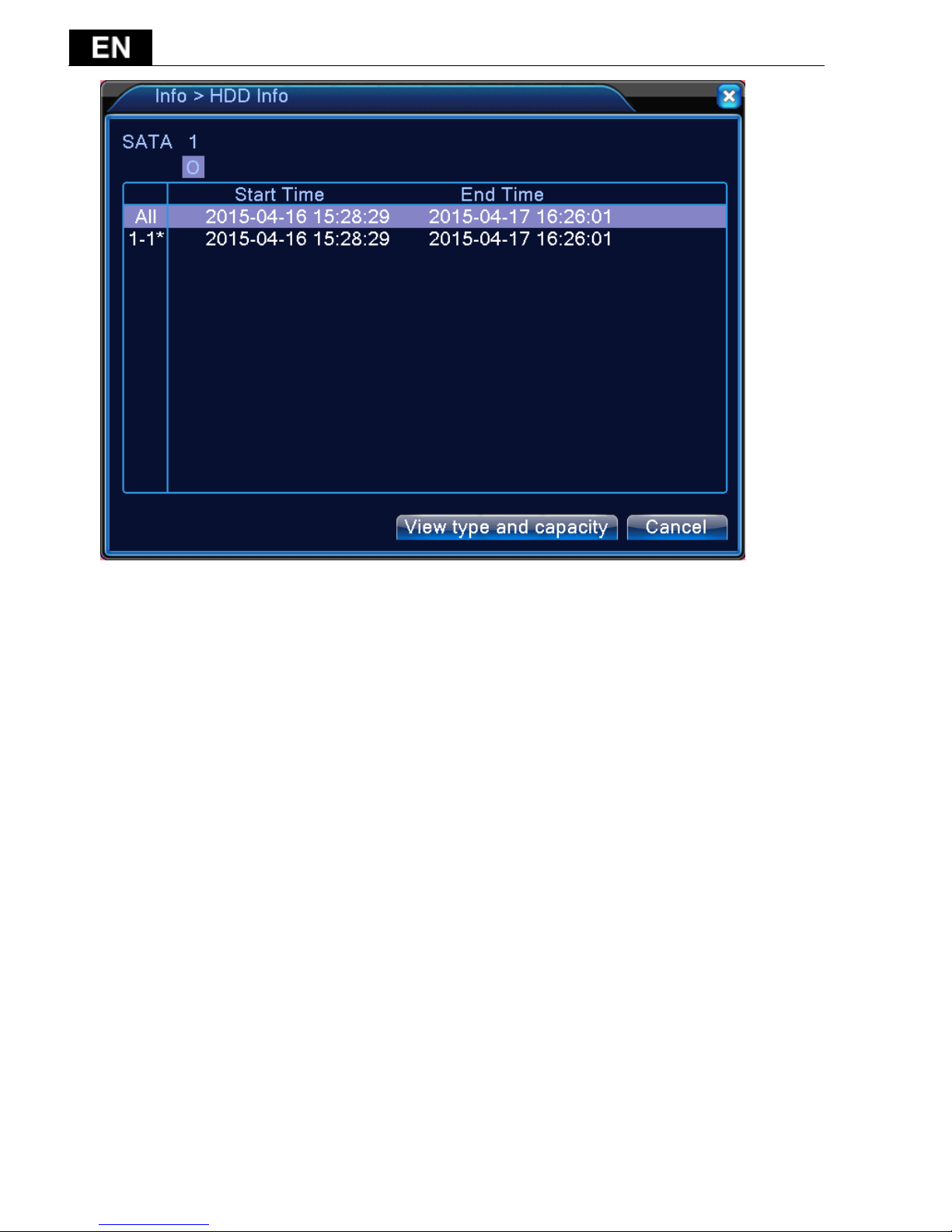
4.6.1 HDD info
Display the hard disk state: hard disk type, overall capability, residual
capability, the recording time and so on.
- 144 -
Pic 4.58 HDD info
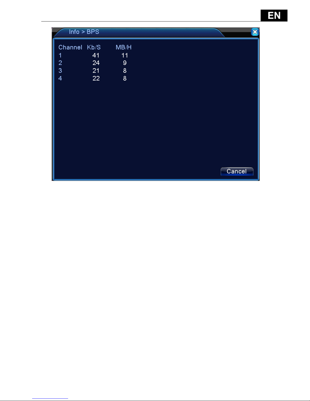
4.6.2 BPS
Display the code stream(Kb/S)and hard disk capability (MB/H)in real time.
It displays as the wave sketch map.
- 145 -
Pic 4.59 BPS
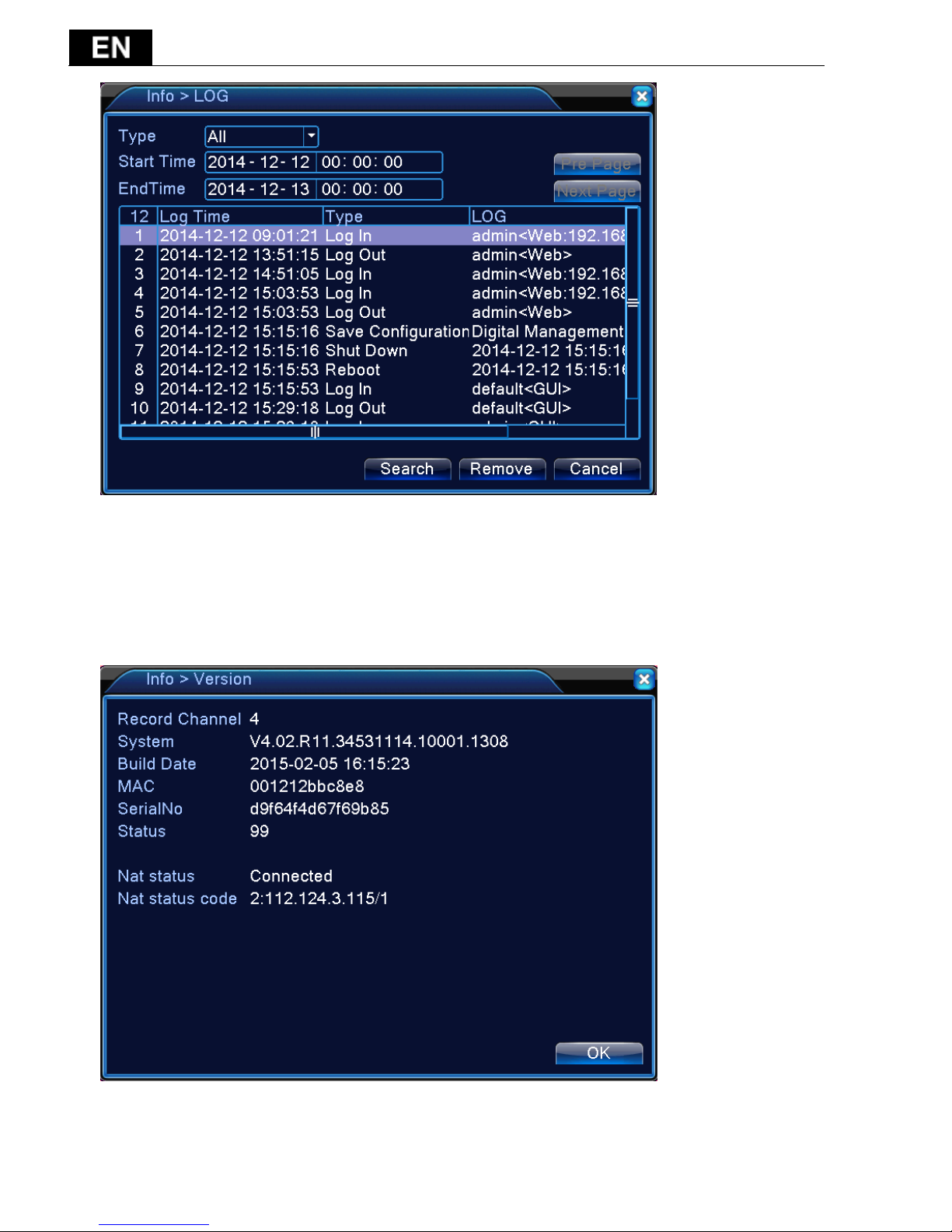
4.6.3 LOG
To search log information base on the set search mode.
Log information include: system operation, configuration operation, data
management, alarm affair, recording operation, user management, file
management and so on. Set the time section to look up and click the look up
button. The log information will display as a list. (one page is 128 items) Press
Page up or Page down button to look up and press delete button to clear all the
log information.
- 146 -
Pic: 4.60 Log information
4.6.4 Version
Display the basic information such as hardware information, software version,
issue date, serial number, NAT status and so on.
Pic 4.61 version information

- 147 -
4.7 Shut down system
5 FAQ
5.1 FAQ
1. The DVR can not boot up normally.
Possible reasons are as followed:
1 The power supply is not correct.
2 Switch power supply line is not in good connection.
3 Switch power supply is damaged.
4 The program updating is wrong.
5 The hard disk is damaged or the hard disk lines are broken.
6 The front panel is damaged.
7 The main board of the DVR is damaged.
2. The DVR reboots automatically or stops working after boot up a few
minutes.
Possible reasons are as followed:
1 The input voltage is not stable or too low.
2 The hard disk is damaged or the hard disk lines are broken.
3 The power of the switch power supply is low.
4 Frontal video signal is not stable.
5 Bad heat radiator or too much dust or bad running circumstance for

- 148 -
the DVR.
6 The hardware of the DVR is damaged.
3. System can not detect hard disk.
Possible reasons are as followed:
1 The hard disk power supply line is not connected.
2 The cables of the hard disk are damaged.
3 The hard disk is damaged.
4 The SATA port of main board is damaged.
4. There are no video outputs in single channel, multiple channels and
all channels.
Possible reasons are as followed:
1 The program is not matched. Please update the program.
2 The image brightness is all 0. Please restore the default setup.
3 There is no video input signal or the signal is too weak.
4 The channel protection or the screen protection is set.
5 The hardware of the DVR is damaged.
5. Real-time image problems such as the image color or the brightness
distortion.
Possible reasons are as followed:
1 When using the BNC output, the option between the N mode or PAL
mode is wrong and the image becomes black and white.
2 The DVR is not matched the monitor impedance.
3 The video transmission distance is too far or the loss of the video
transmission line is too large.
4 The color and brightness setting of the DVR is wrong.
6. I can not find the video files in local playback mode.
Possible reasons are as followed:
1 The data line of the hard disk is damaged.
2 The hard disk is damaged.
3 Update the different program with the origin program files.
4 The video files to look up are covered.
5 The recording is not on.
7. The local video is not clear.

- 149 -
Possible reasons are as followed:
1 The image quality is too bad.
2 The reading program is wrong. Reboot up the DVR.
3 The data line of the hard disk is damaged.
4 The hard disk is damaged.
5 The hardware of the DVR is damaged.
8. There is no audio signal in the surveillance window.
Possible reasons are as followed:
1 It is not an active tone arm.
2 It is not an active sound box.
3 The audio lines are damaged.
4 The hardware of the DVR is damaged.
9. There is audio signal in the surveillance window but no audio signal in
the playback state.
Possible reasons are as followed:
1 Setting issues: the audio option is not chosen.
2 The according channel is not connected with the video.
10. The time is wrong.
Possible reasons are as followed:
1 Setting is wrong.
2 The battery is in bad connection or the voltage is too low.
3 The oscillation is damaged.
11. The DVR can not control the PTZ.
Possible reasons are as followed:
1 There is something wrong with the frontal PTZ.
2 The setting, connection or the installation of the PTZ decoder is
not correct.
3 The connections are not correct.
4 The PTZ setting of the DVR is not correct.
5 The protocols of the PTZ decoder and the DVR are not matched.
6 The address of the PTZ decoder and the DVR are not matched.
7 When multiple decoders are connected, the far port of the PTZ
decoder line A(B) must connect a 120 resistance to reduce the

- 150 -
reflection otherwise the PTZ control is not stable.
8 The distance is too far.
12. The motion detect is not working,
Possible reasons are as followed:
1 The time range set is not correct.
2 The motion detect area set is not correct.
3 The sensitivity is too low.
4 Limited by some hardware edition.
13. I can not login via web or CMS.
Possible reasons are as followed:
1 The system is windows 98 or win me. We recommend updating to
windows 2000sp4 or higher Version or installing the software for
low edition.
2 ActiveX is hold back.
3 The version is not exceeded dx8.1. Update the display card driver.
4 Network connection failure.
5 Network setting issues.
6 Invalid password or user name.
7 The CMS is not matched the DVR program version.
14. The image is not clear or there is no image in network preview state
or video file playback state.
Possible reasons are as followed:
1 Network is not stable.
2 The user machine is resource limited.
3 Choose the play-in-team mode in the network setup of DVR.
4 The region shelter or channel protection is set.
5 The user has no surveillance purview.
6 The real-time image of the hard disk recording machine itself is not
clear.
15. Network connection is not stable.
Possible reasons are as followed:
1 Network is not stable.
2 IP address is conflicted.

- 151 -
3 MAC address is conflicted.
4 The net card of the DVR is bad.
16. There is something wrong with the USB backup or writing a CD.
Possible reasons are as followed:
1 The rewritable machine and the hard disk are shared the same data
lines.
2 The data is too much. Please stop recording and backup.
3 The data exceeds the backup storage.
4 The backup equipment is not compatible.
5 The backup equipment is damaged.
17. The remote controller is not working,
Possible reasons are as followed:
1 The remote control address is not correct.
2 The remote control distance is too far or the angle is too large.
3 The battery is used up.
4 The remote controller or the front panel of the recording machine
is damaged.
18. The storage time is not enough.
Possible reasons are as followed:
1 Front video quality is bad. The lens is too dirty. The video is in
backlighting installation.
2 The hard disk capability is not enough.
3 The hard disk is damaged.
19. The downloading files can not play.
Possible reasons are as followed:
1 There is no media player.
2 There is no DX8.1 software or higher edition.
3 There is no DivX503Bundle.exe file to play AVI video files.
4 The DivX503Bundle.exe and ffdshow-2004 1012 .exe files must be
installed in the windows xp system.
4 output circuit easily.
5 Do not turn off the switch directly. Please use the turn-off function
in the menu or press the turn-off button in the panel (3 seconds or

- 152 -
longer) to protect the hard disk.
6 Please keep the DVR away from heat resource.
7 Please keep the DVR ventilated for better heat radiator.
5.2 Maintenance
1. Please ensure the system is grounded to prevent video or audio signal
interference and the DVR from static or inductive electricity.
2. Do not disconnect the video signal line, RS-232 port, or RS-485 port with the
power on.
3. Do not connect a TV to the local video output port (VOUT) of DVR. It will
damage the video output circuit.
4. Please keep the DVR away from heat resource.
5. Please keep the DVR ventilated for better heat radiation.
6. Please check the system and maintain regularly.
- 153 -
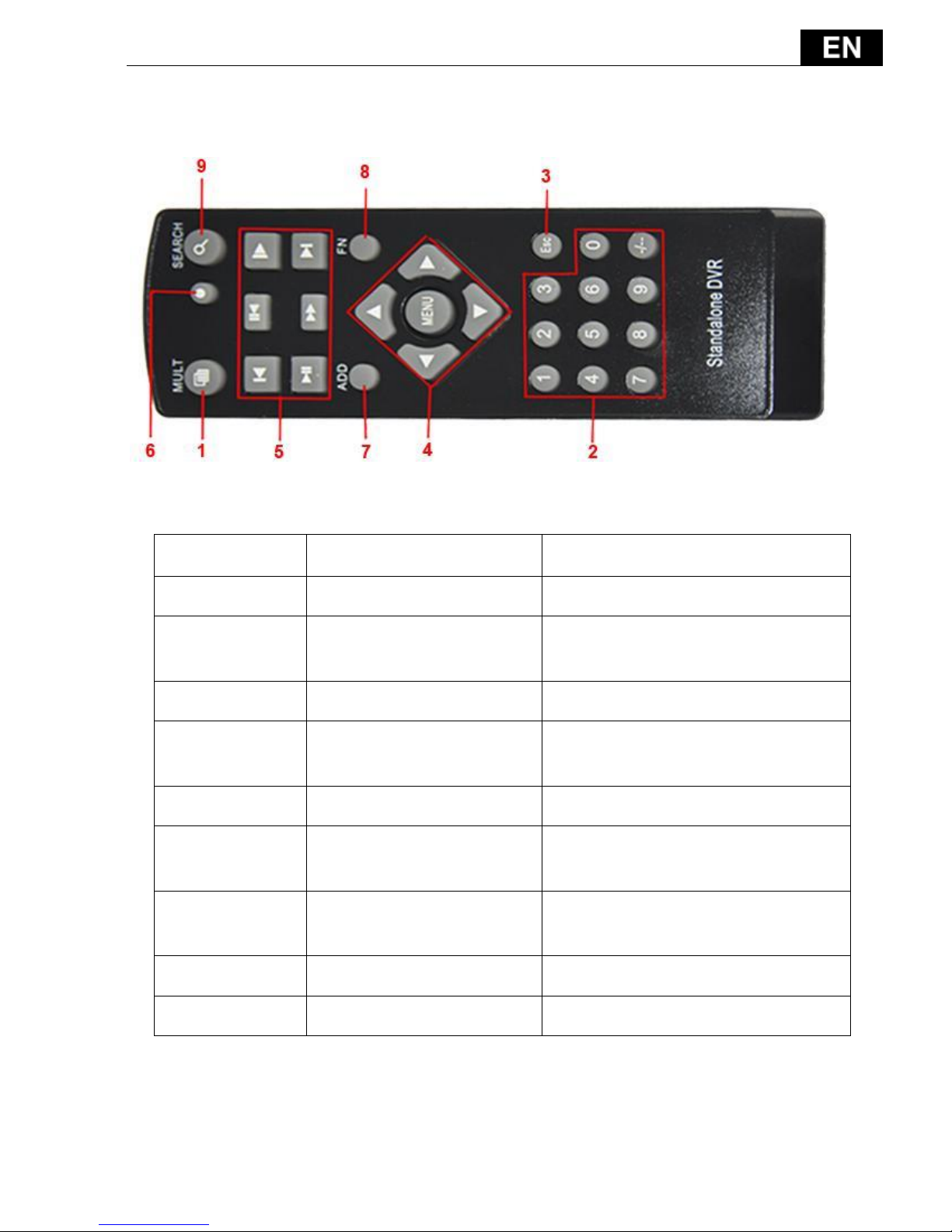
Appendix 1. Remote control operation
Serial number
Name
Function
1
Multi-window button
Split screens button
2
Numeric button
Code input/number
input/channel switch
3
【Esc】
Exit button
4
Direction button
Up, Down, Left, Right and
Enter/Menu button.
5
Record control
Control the record
6
Record mode
Enter short menu as “record
mode” button
7
ADD
Input the number of DVR to
control it
8
FN
Assistant function
9
Search
Search record files to playback.

- 154 -
Appendix 2. Mouse operation
The USB ports support mouse operations.
NOTE: Units with front and rear mouse USB ports can only utilize one port at a
time – if a USB device is connected to one of the ports the other is automatically
deactivated. The bottom rear USB port is designated for USB backup drives.
Operation
Function
Double left click
Double click one item in the file list to playback the
video. Double click the playback video to zoom in or
out.
Double click the channel to make it display full screen.
Double click again to resume the multi-window display.
Left click
Choose the associated function in the menu
Right click
Open the desktop shortcut menu in a preview state
Current shortcut menu in the main menu
Press middle
button
Add or subtract number in the number setting
Switch the items in the combo box
Page up or down in the list
Move mouse
Choose the widget or move the item in the widget
Drag mouse
Set the motion detect area
Set the cover area

- 155 -
Appendix 3. Hard disk capability calculation
Verify the following when installing the hard drive in the DVR for the first
time:
Hard disk capacity
There is no limit for recording machine. We recommend 120G~ 250G sizes to
keep better stability.
Overall capacity option
The hard disk capacity formula is:
Overall capacity(M)= channel number*time(hour)*capacity in an hour(M/hour)
The recording time formula is:
Recording time(hour)=
overall capacity(M)
Capacity in an hour(M/hour)*channel number
The DVR introduces the H.264 compression technology. Its dynamic range is
very large so the hard disk capacity calculation is based on the estimation values
of each channel creating files in an hour.
Example:
For one 500G HDD, real time CIF for recording, it will keep recording for about
25 days. HDD spaces per channel are 200M/H, if 4channels real time CIF at
24hours recording uninterrupted, it can last: 500G/(200M/H*24H*4ch) = 26 days.

DETECTIVE S4CIH7D
www.evolveo.eu
 Loading...