

Detective DV4
www.evolveo.com
Warning:
Follow these safeguards to
avoid death or serious injury.
Caution: Follow these precautions to prevent
injury or property loss.
Statement:
Thanks for purchasing from us. Please feel free to contact our service whenever
you need help.
This manual is applicable for NVR products. Features and functions vary with
different products, please refer to our physical commodity and the fast manual.
This manual is your reference for operations and encodings. Related
functions, specific orders, detailed menu-tree as well as fast manual are
included. Please read it before installation or use.
This manual might contain some technical or print errors. Any enhancement in product
features shall be added into the manual consistently without further notice.
Safety Instruction
This manual is intended to ensure that user can use the product properly without danger or any
property loss. Please read it carefully and take care of it for further reference.
Precaution measures are divided into “warnings” and “cautions”, as below:
Warnings: Neglecting any of the warnings may cause death or serious injury.
Cautions: Neglecting any of the cautions may cause injury or equipment damage.

Warnings
1. Electrical safety regulations of the nation and the region must be strictly followed during installation
or use.
2. Please use the matched power adapter from standard company.
3. Do not connect multiple DVRs with one single power adapter (Overload for adapter may lead to
over-heat or fire hazard.
4. Shut down the power while connecting or dismounting the speed dome. Do not operate with power
on.
5. Shut down the power and unplug the power cable immediately when there is smoke, odor or noise
rising from the DVR. Please contact the dealer or service center.
6. Please contact the local dealer or latest service center when DVR works abnormally. Do not attempt
to disassemble or modify the device yourself. (We shall shoulder no responsibility for problems caused
by unauthorized repair or maintenance.
Cautions
1. Do not drop anything onto the dome, avoid it from physical strike. Keep it away from high
electromagnetism radiation surroundings. Do not install it at vibration surface or places subjecting to
strike. (Ignorance can cause equipment damage)
2. Keep it away from rain and moisture
3. Avoid exposing to direct sunlight, poor-ventilation or heat source such as heater, radiator.
(Ignorance can cause fire hazard)
4. To avoid physical damage, extreme environment such as lampblack, water vapor, too hot or dusty
are not allowed.
5. Please use soft and dry cloth to clean the shell. Use neutral cleaner instead of alkaline when the
dirt is difficult to get rid of.

Directory
1 Product Introduction .............................................................................................................................................6
1.1 Product overview ..........................................................................................................................................6
1.2 Main functions ..............................................................................................................................................6
2 Open-package check an d cable connections...................................................................................................7
2.2 Hard disk installation ....................................................................................................................................8
2.3 Shelf installation ...........................................................................................................................................8
2.4 Front panel ....................................................................................................................................................9
2.5 Rear panel ...................................................................................................................................................10
2.6 Audio and video input and output connections ...........................................................................................12
2.6.1 Video input connections ..............................................................................................................12
2.6.2 Video output connections and options ......................................................................................12
2.6.3Audio signal input ..........................................................................................................................12
2.6.4Audio signal output........................................................................................................................12
2.7 Alarm input and output connections ...........................................................................................................13
2.7.1 Alarm input port specification......................................................................................................15
2.7.2 Alarm output port specification ...................................................................................................15
2.7.3 Alarm output port relay parameters ...........................................................................................15
2.8 Device attachment.......................................................................................................................................16
3 Basic operation....................................................................................................................................................16
3.1 Turn on ........................................................................................................................................................16
3.2 Turn off .......................................................................................................................................................17
3.3 System Login ..............................................................................................................................................17
3.4 Preview .......................................................................................................................................................18
3.5 Desktop shortcut menu................................................................................................................................19
3.5.1 Main menu.....................................................................................................................................20
3.5.2 Record Control..............................................................................................................................22
3.5.3 Playback ........................................................................................................................................23
3.5.5 Alarm output ..................................................................................................................................25
3.5.6 PTZ control ....................................................................................................................................26
3.5.7 Color setting ..................................................................................................................................31
3.5.8 Output Adjust.................................................................................................................................32
3.5.9 Logout ............................................................................................................................................33
4.1 Main menu navigation ................................................................................................................................33
4.2 Record .........................................................................................................................................................36
4.2.1Playback .........................................................................................................................................37
4.2.2 Backup ...........................................................................................................................................37
4.3 Alarm Function ...........................................................................................................................................39
4.3.1 Motion Detect ................................................................................................................................39
4.3.2 Video Blind ....................................................................................................................................42
4.3.3 Video Loss .....................................................................................................................................42

4.3.4 Alarm input.....................................................................................................................................43
4.3.5 Alarm output ..................................................................................................................................44
4.3.6 Abnormal........................................................................................................................................44
4.4 System setup ...............................................................................................................................................45
4.4.1 General ..........................................................................................................................................46
4.4.2 Network setup ...............................................................................................................................47
4.4.3 Net Service ....................................................................................................................................48
4.4.4 Output mode .................................................................................................................................57
4.4.5 Serial port settings........................................................................................................................58
4.4.6 Tour.................................................................................................................................................59
4.4.7 Channel manage ..........................................................................................................................59
4.5 Advanced.....................................................................................................................................................66
4.5.1 HDD Manage ................................................................................................................................66
4.5.2 Account ..........................................................................................................................................67
4.5.3 Online user ....................................................................................................................................70
4.5.4 Output adjust.................................................................................................................................70
4.5.5 Auto Maintain ................................................................................................................................71
4.5.6 Restore...........................................................................................................................................71
4.5.7 Upgrade .........................................................................................................................................72
4.5.8 Device Info.....................................................................................................................................72
4.5.9 Import / Export ..............................................................................................................................72
4.6 Info ..............................................................................................................................................................73
4.6.1 HDD info ........................................................................................................................................73
4.6.2 BPS.................................................................................................................................................74
4.6.3 LOG ................................................................................................................................................75
4.6.4 Version ...........................................................................................................................................76
4.7 Shut down system .......................................................................................................................................77
5 Cloud Technology Basic Operation ..................................................................................................................77
6 FAQ and maintenance .......................................................................................................................................82
6.1 FAQ.............................................................................................................................................................82
6.2 Maintenance ................................................................................................................................................88
Appendix 1.Remote controller operation ............................................................................................................89
Appendix 2.Mouse operation................................................................................................................................90
Appendix 3.Hard disk capability calculation .......................................................................................................91

7 / 91
1 Product Introduction
1.1 Product overview
The series NVR is designed specially for security and defense field which is an outstanding digital
surveillance product. It introduces embedded LINUX operating system which is more stable. It introduces
standard H.264mp video compressed format and unique space-time filtering algorithm which insures the
high quality image, low error coding ratio and single frame playing. It introduces TCP/IP network
technology which achieves the strong network communication ability and telecommunication ability.
The series NVR can be used individually or online applied as a part of a safety surveillance network.
With the professional network video surveillance software it achieves the strong network communication
ability and telecommunication ability.
The series DVR can be applied in the bank, telecom, electric power system, judicial system,
transportation, intelligent housing, factory, storehouse, water conservancy and so on.
1.2 Main functions
Real-time surveillance
Spot interface, analog interface, VGA interface and HDMI interface surveillance function through monitor
or display.
Storage
Non-working disk dormancy processing which is convenient to radiate heat, reduce power and extend the
life-span
Special storage format which insures the data safety
Compression
Real-time compression by individual hard disk which insures the audio and video signal stable
synchronization
Backup
Through SATA interface and USB interface such as USB equipment, removable hard disk and so on
Through net download the files in the hard disk
Playback
Individual real-time video recording as well as searching, playback, network surveillance, recording check,
downloading and so on
Multi-playback mode

8 / 91
Zoom at arbitrary region
Net operating
Through net (including telephone) tele-surveillance in the real time
Tele-PTZ control
Tele-recording check and real-time playback
Alarm linkage
Alarm activated video record, tour, message, buzzer, e-mail, ftp, cell phone to report
Communication interface
RS485 interface which fulfills the alarm input and PTZ control
RS232 interface which can extend keyboard connection to realize master, as well as with computer serial
port connection for system maintenance and upgrade, and matrix control and so on.
Standard Ethernet network interface which fulfills the telecommuting function
Intelligent operating
Mouse action function
Fast copy and paste operating for the same setting

9 / 91
2 Open-package check and cable connections
2.1 Out of box audit
When you receive the product,
Materials used for the package of the NVR can protect most accidental clashes during transportation.
Then, please open the box and get rid off the plastic protective materials. Check whether there is any
visible damage to the NVR appearance.
At last, please open the machine crust and check the data wire in the front panel, power wire, the
connection between the fan power and the main board.
1. Front panel and rear panel
The key function specification in the front panel and the interface specification in the real panel
are in the specification.
Please check the product type in the front panel whether is accordant with the product type you
order.
10 / 91
The label in the real panel is very important for the after service. Please protect it carefully. When
you contact us for after service, please provide the product type and serial number in the label.
2. Check
After open the cover, you should check if it has obvious damage trace, also please check the
front panel data cable, power cord and motherboard's connection are loose or not.
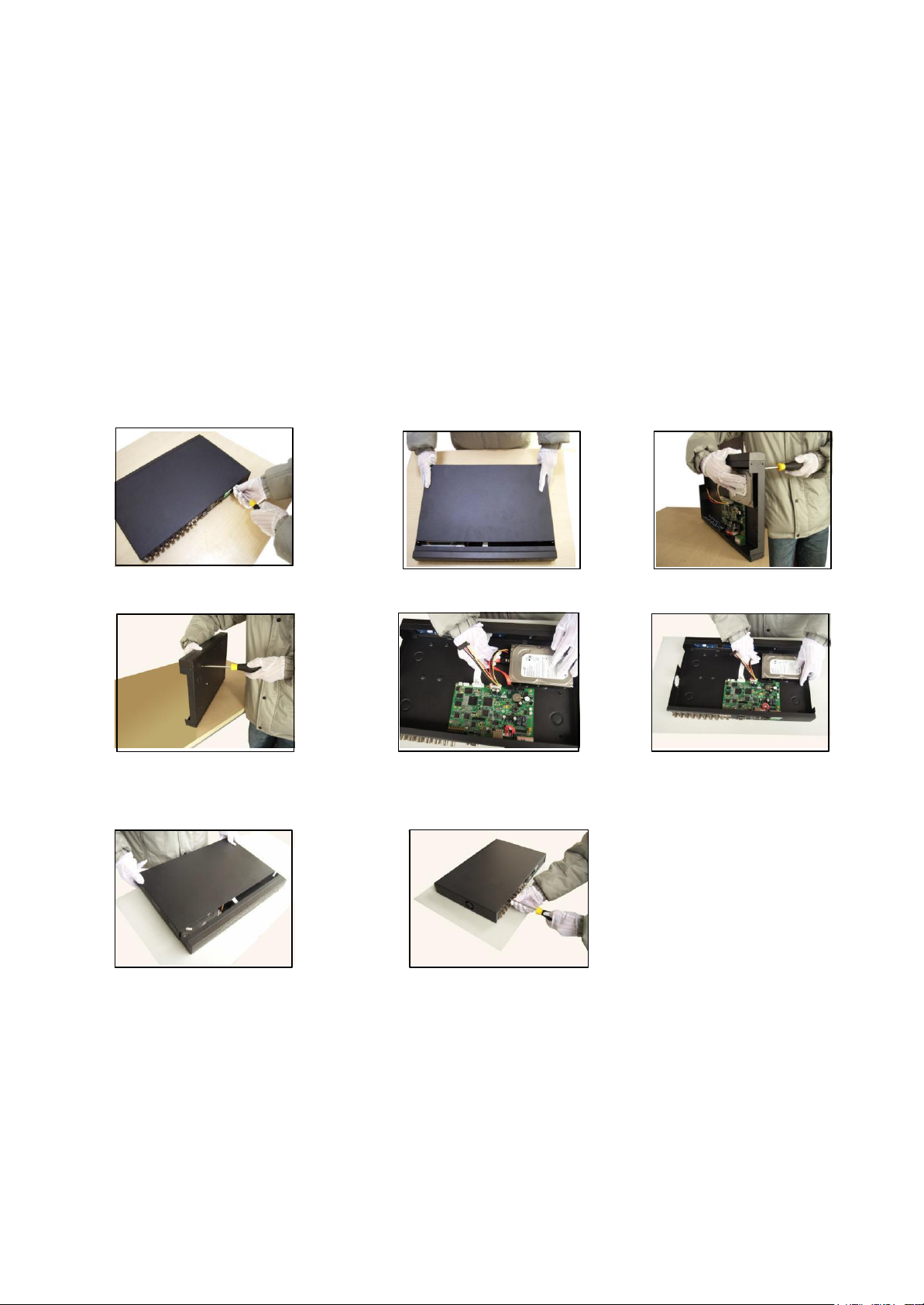
2.2 Hard disk installation
For the first use, please install the hard disk, this machine box can install two hard disk (no limited
capacity).
①disassemble the screw ②disassemble the cover ③fix the screw of hard disk
④fix the screw of hard disk ⑤connect the data wire ⑥connect the power wire
⑦cover the machine ⑧fix the cover
2.3 Shelf installation
This product chassis specification for the standard 1u, so it can be installed in the standard shelf.
Installation steps and attention items:
1、Make sure the temperature in the room lower than 35℃ (95°f).
11 / 91
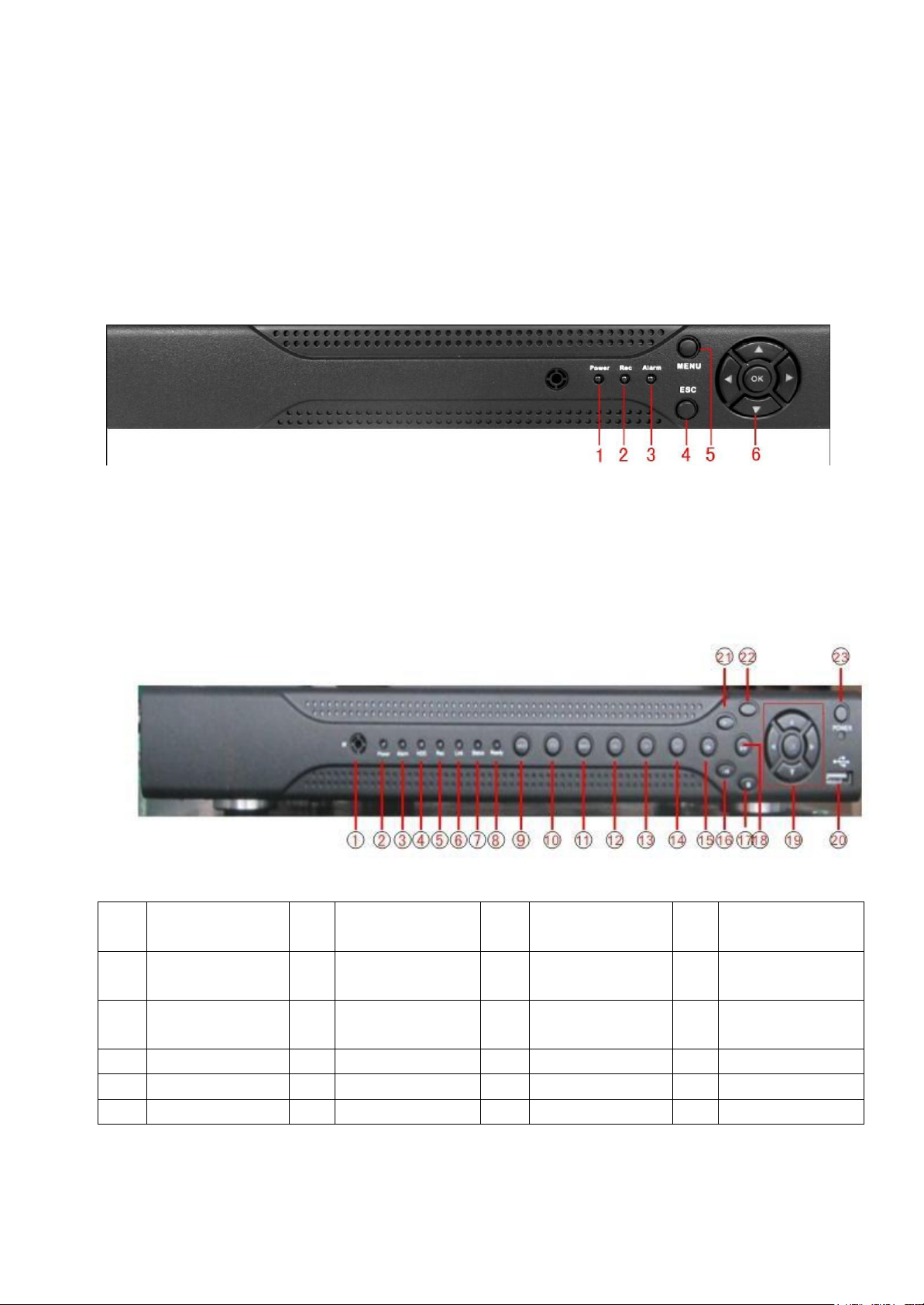
(1) Power indicator light
(2) Record indicator light
(3)Alarm indicator light
(4) ESC
(5) Menu
(6)Direction &Enter
(1)
IR remote
receiver
(2)
Power indicator
light
(3)
Alarm indicator
light
(4)
Keyboard
indicator light
(5)
Record indicator
light
(6)
Network indicator
light
(7)
Status indicator
light
(8)
Previous File
(9)
Return main
menu
(10)
PTZ
(11)
Playback
(12)
Previous File
(13)
Next file
(14)
Record
(15)
Slow Play
(16)
Playback pause
(17)
Fast Play
(18)
Play back Stop
(19)
Direction&Enter
(20)
USB
(21)
Stop Play
(22)
ESC
(23)
Power Switch
2、Keep the equipment have 15cm (6 inches) space around in order to air's circulation.
3、From bottom to shelf installation.
4、When multiple components install in the frame please take preventive measures to avoid
power socket overload.
2.4 Front panel
The front panel of economical equipment
The front panel of standard equipment
12 / 91
The front panel of enhanced equipment
(1) Shuttle (2) Play Pause (3) Slow Play (4) Fast Play (5) Backwards Pause (6) Play back Stop
(7) Record (8)
Power switch (9) USB mouse (10)
Indicator light (11) Main menu (12)Scene switch
(13) Record check (14) PTZ (15) Assist (16) Shift (17) ESC (18) IR remote receiver (19) Direction
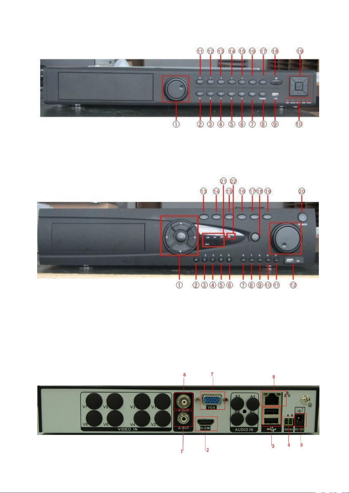
The front panel of high-end equipment
(1) Direction (2) Play Pause (3) Previous File (4) Next File (5) Backwards Pause (6) Play back
Stop (7) Record check (8) Alarm output
(9) Camera narrow (10)
Camera zoom (11) Preset point set
(12) USB (13) ESC (14) Scene switch (15) Record (16) PTZ (17) Menu (18) Assist (19) Shift
(20)
Power switch (21)
Indicator light (22) IR remote receiver
2.5 Rear panel
The rear panel of economic and standard equipment
13 / 91
(1) Audio output (2) HDMI (3) USB (4) RS485 (5) Power (6) BNC (7) VGA (8) Network
The rear panel of enhanced equipment
(1) Audio Input (2) HDMI (3) USB (4) Network (5) VGA (6) External Interface (7) Power Supply
(8) BNC (9) Audio Input (10) RS485 (11) Power switch
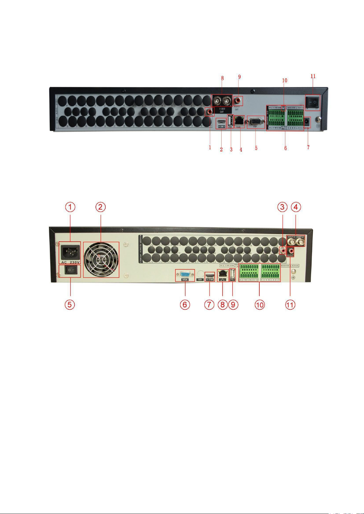
The rear panel of high-end equipment
(1) Power (2) Cooling mouth (3) Audio Input (4) Video output (5) Power switch (6) VGA Interface (7) HDMI
(8) Network (9) USB (10) External (11) Audio output
2.6 Audio and video input and output connections
2.6.1 Video input connections
There is no video input connection.
Insure the vision signal stable and credible
The vision should be installed in the appropriate location where is away from backlighting and low
illumination or adopts the better backlighting and low illumination compensation.
The ground and power supply of the vision and the DVR should be shared and stable.

14 / 91
2.6.2 Video output connections and options
The video output is divided into PAL/NTSC BNC (1.0V
(selective configuration).
When replace the monitor by the computer display, there are some issues to notice
1. Do not stay in the turn-on state for a long time.
2. Keep the computer display normal working by demagnetizing regularly.
3. Stay away from the electromagnetic Interference.
TV is not a credible replacement as a video output. It demands reducing the use time and control the
power supply and the interference introduced by the nearby equipment strictly. The creepa ge of low quality
TV can lead to the damage of other equipments.
2.6.3 Audio signal input
, 75Ω) and VGA output
P-P
Audio port is BNC connection.
The input impedance is high so the tone arm must be active.
The audio signal line should be firm and away from the electromagnetic Interference and connected
credible which avoid false and joint welding and oxidation. The high voltage current should be avoided
especially.
2.6.4 Audio signal output
Commonly the output parameter of DVR audio signal is greater than 200mv 1KΩ (BNC) which can
connect the low impedance earphone and active sound box or other audio output equipments through

15 / 91
power amplifier. If the sound box and the tone arm cannot be isolated, howling phenomena is often
existed. There are some methods to deal with the above pheno mena.
1. Adopt better directional tone arm.
2. Adjust the sound box volume to be under the threshold that produces the howling phenomena.
3. Use fitment materials that absorb the sound to reduce reflection of the sound.
4. Adjust the layout of the sound box and the tone arm.
2.7 Alarm input and output connections
Before connecting the device, please pay attention to follow situations:
*note: Some products have no alarm input/output functions.
1.Alarm input
A. Alarm input is grounding alarm input.
B. Alarm input demand is the grounding voltage signal.
C. When the alarm is connected with two DVRs or connected with DVR and other equipments, it
should be isolated by relay.
2. Alarm output
Alarm output cannot be connected with high-power load (no more than 1A).When forming the output
loop it must prevent the big current from relay damage. Use the contact isolator when there is a
high-power load
3. PTZ decoder connections
A. The grounding of the PTZ decoder and DVR must be shared otherwise the common-mode
voltage will lead to the PTZ control failure. The shielded twisted pair is recommended.
B. Avoid the entrance of high voltage. Make the layout reasonably. Take precaution from the
thunder.
C. In the outlying end connect 120Ω resistance paralleled to reduce the inflection and insure the
signal quality.
D. The 485 AB lines of DVR cannot connected with other 485 output equipments paralleled.
E. The voltage between the AB lines of the decoder must be less than 5V.
4. Front equipment grounding note
Bad grounding can lead to the burnout of the chip.
5. Alarm input type unlimited
16 / 91
The NVR alarm output port is constant opening type.
Parameter
meaning
G
grounding
R,T
RS232 port
A,B
485communciate interface which is connected with the
recording control equipments such as the decoder
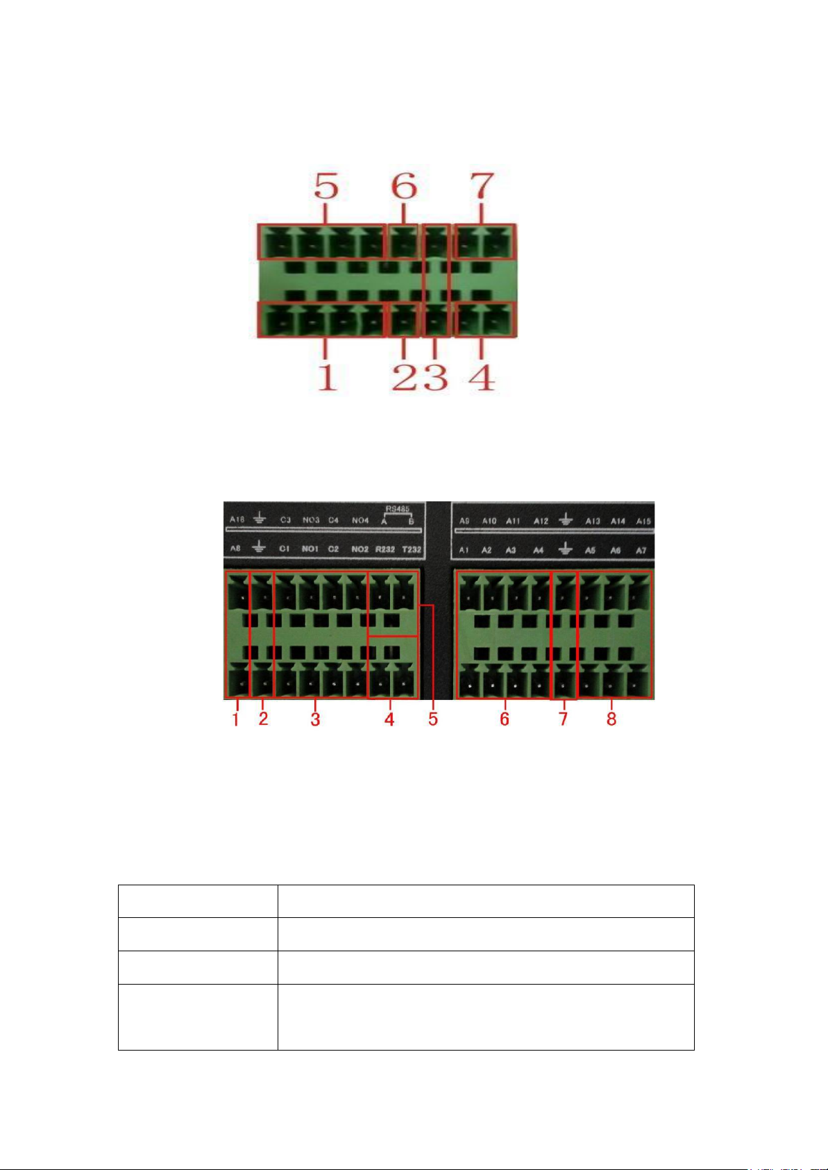
Eight external alarm interface
(1) Alarm input 1,2,3,4 (2) ground (3) RS232 (4) RS485 (5) Alarm input 5,6,7,8
(6) Ground (7) Alarm output
Sixteen external alarm interface
①⑥⑧alarm input ②⑦ground ③alarm output ⑤RS485 ④RS232

17 / 91
2.7.1 Alarm input port specification
Type:JRC-27F
Interface material silver
rating
(resistance load)
Rating switch capacity
30VDC 2A, 125VAC 1A
maximal switch power
125VA 160W
maximal switch voltage
250VAC, 220VDC
maximal switch current
1A
isolation
Homo-polarity interface
1000VAC 1minute
Inhomo-polarity
1000VAC 1 minute
Interface and winding
1000VAC 1 minute
Surge voltage
Homo-polarity interface
1500VAC (10×160us)
Turn-on time 3ms max
Turn-off time 3ms max
longevity
mechanical
50×106
MIN(3Hz)
electric
200×103
MIN (0.5Hz)
Environment
-40~+70℃
8 channels alarm input. Alarm input type unlimited.
The grounding and the com port of the alarm sensor are parallel (The alarm sensor is external power
supply).
The grounding of the alarm and the DVR should be shared.
The NC port of the alarm sensor must be connected with the DVR alarm input port.
The grounding of the power supply and the alarm sensor must be shared when used in external power
supply.
2.7.2 Alarm output port specification
2 channels alarm output. There is external power supply when using the external alarm equipment.
Please refer to the relay relevant parameters to avoid the overload that damages main machine.
2.7.3 Alarm output port relay parameters
18 / 91
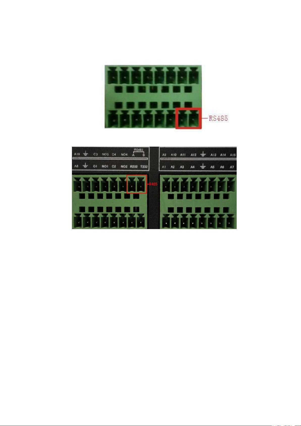
2.8 Device attachment
1. Connect the 485 lines of the speed dome with the DVR 485 interface.
The 485 interface of eight external alarm
The 485 interface of sixteen external alarm
2. Connect the video line with the DVR video input.
3. Electrify the speed dome
3 Basic operation
Note: The button in gray display indicates nonsupport.
3.1 Turn on
Plug the power supply and turn on the power supply switch. Power supply indicator light shining
indicates turning on the video recorder. After the start up you will hear a beep. The default setting of video
output is multiple-window output mode. If the startup time is within the video setting time, the timing video
recording function will start up automatically. Then the video indicator light of corresponding channel is

19 / 91
Shining and the DVR is working normally.
Note:1. Make sure that the input voltage corresponds with the switch of the DVR power supply.
2. Power supply demands: 220V±10% /50Hz.
Suggest using the UPS to protect the power supply under allowable conditions.
3.2 Turn off
There are two methods to turn off the DVR. Entering [main menu] and choosing [turn off] in the [turn
off the system] option is called soft switch. Pressing the power supply switch is called hard switch.
Illumination:
1. Auto resume after power failure
If the DVR is shut down abnormally, it can automatically backup video and resume previous
working status after power failure.
2. Replace the hard disk
Before replacing the hard disk, the power supply switch in the real panel must be turned off.
3. Replace the battery
Before replacing the battery, the setting information must be saved and the power supply switch
in the real panel must be turned off. The DVR uses button batt ery. The system time must be checked
regularly. If the time is not correct you must replace the battery, we recommend replacing the battery
every year and using the same battery type.
Note: The setting information must be saved before replacing the battery otherwise
information will lose.
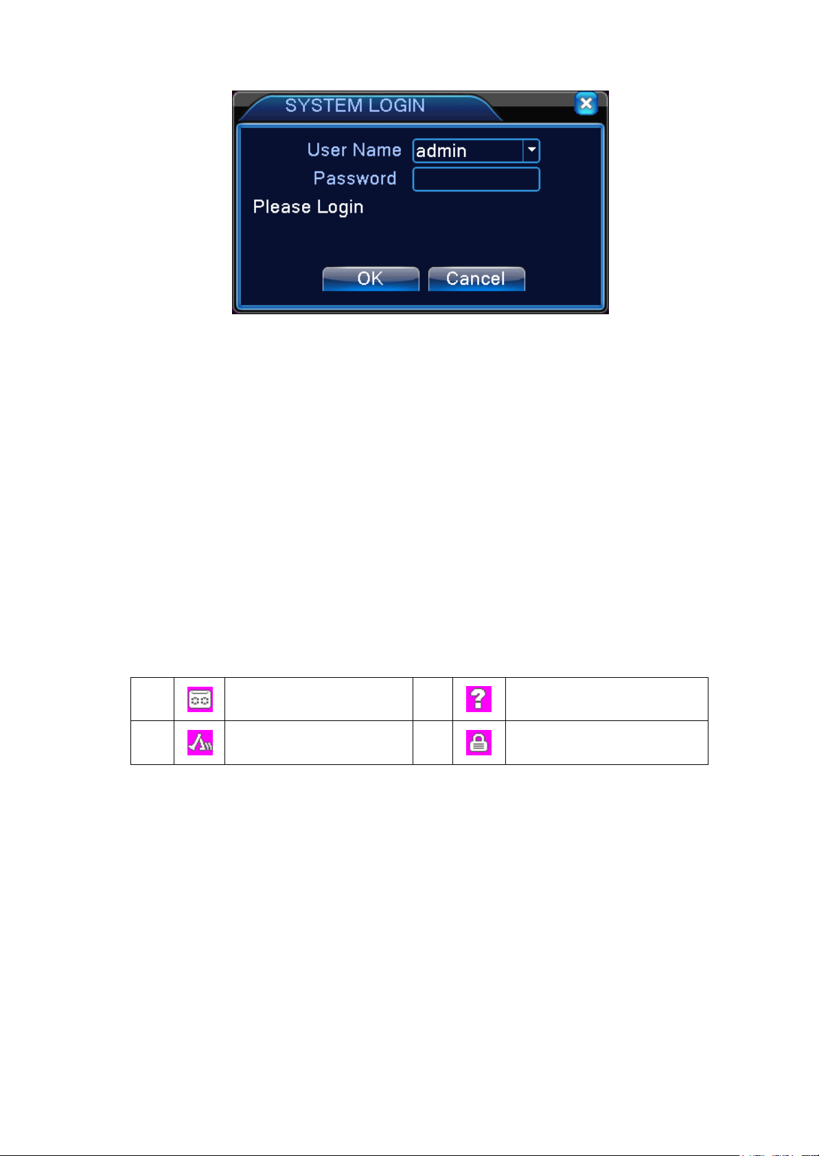
3.3 System Login
When the NVR boots up, the user must login and the system provides the corresponding functions
with the user purview. There are two user settings. The names are admin, and default and these names
have no password. Admin is the super user purview; default’s permissions are preview and video
playback. User admin’s password can be revised, while their permissions can’t be revised; user default
is the default login user whose permission can be revised but not its password.
20 / 91
1
Recording status
3
Video loss
2
Motion detect
4
Camera lock
Picture 3.1 System Login
Password protection: If the password is continuous wrong five times, the alarm will start. If
the password is continuous wrong five times, the account will be locked. (Through reboot or after
half an hour, the account will be unlocked automatically).
For your system security, please modify your password after first login.
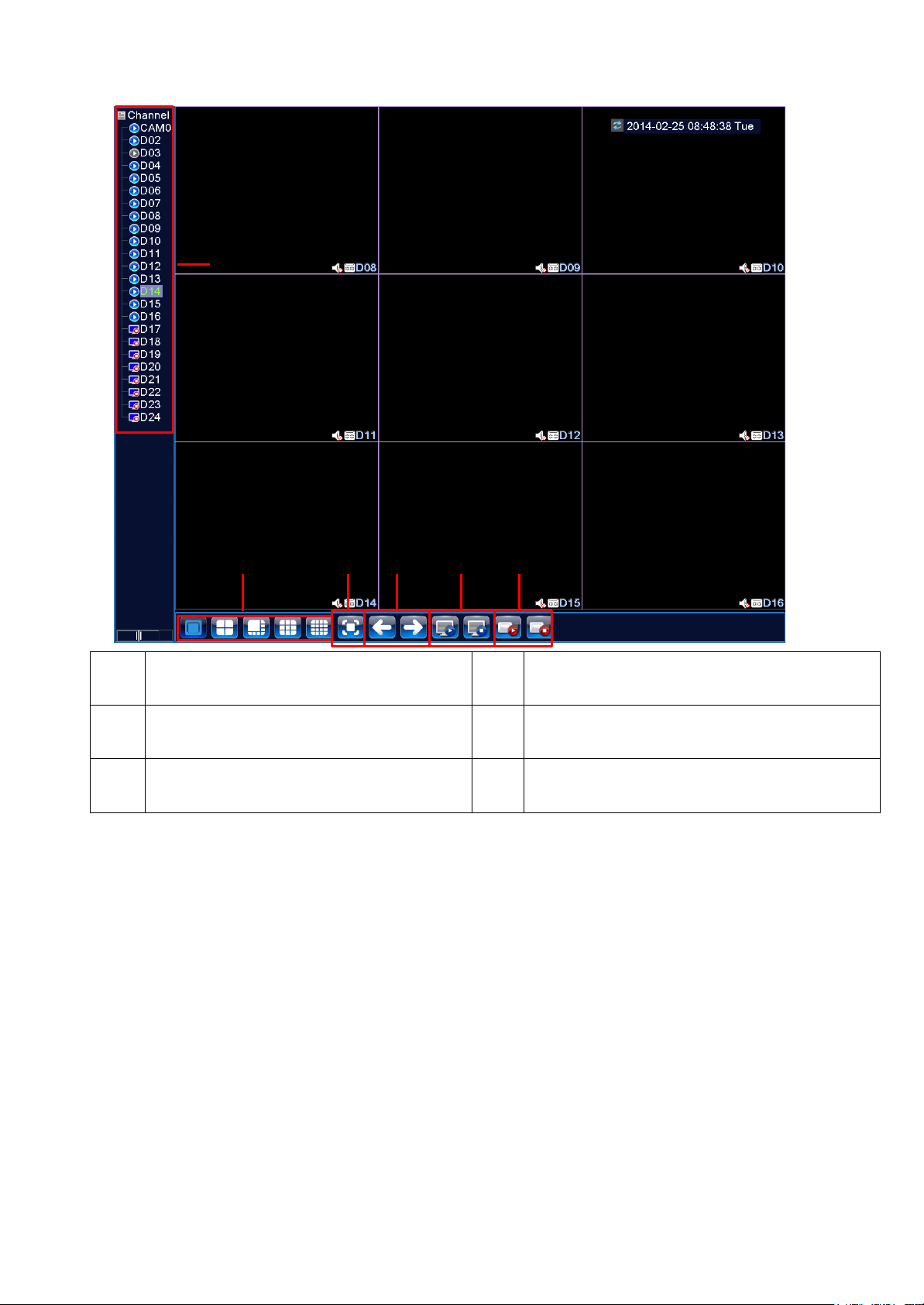
3.4 Preview
You can right click mouse to choose the switch between the windows.
The system date, time and channel name are shown in each viewing window. The surveillance video
and the alarm status are shown in each window.
Table 3.1 Preview icon
21 / 91
(1)
Channel name and status display, click on
the "channel" can be folded up.
(2)
More than one scene changes
(3)
Full screen
(4)
Page flip up and down, when choosing a 16
channel, operation can be performed.
(5)
Play/close all channel
(6)
Full channel video/close full video
1
2 3 4 5 6
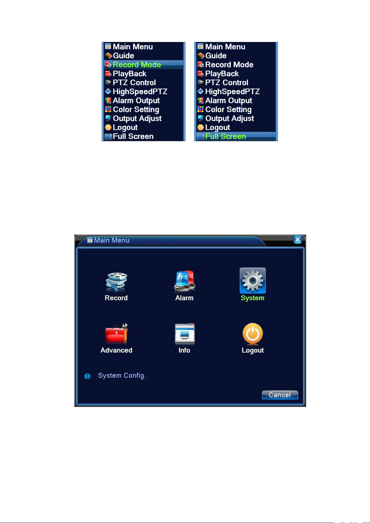
3.5 Desktop shortcut menu
In preview mode you can right click mouse to get a desktop shortcut menu, as the picture 3.2 shows.
The menu includes: main menu, record mode, playback, PTZ control, High Speed PTZ, Alarm
Output, color Setting, Output adjust, Logout, view mode shift ,spot.
*Only partial model of 6000 series support Spot
22 / 91
Not full screen Full screen
3.5.1 Main menu
When you login, the system main menu is shown as below.
Picture 3.3 Shortcut Menu
Picture3.4 Main Menu
3.5.2 Boot wizard
For configuring the parameters provides quick setup wizard as shown in figure 3.5. It includes boot
wizard and digital channel configuration wizard, click next to enter the digital channel configuration
wizard.
Boot wizard:
23 / 91
Picture 3.5 Boot wizard
【Cloud services enable】: reverse display ■choose, means enabling cloud services.
【No longer prompt】: reverse display ■choose, means after reboot, no longer automatically pop up on
the wizard.
【Next】: Enter into the digital channel configuration wizard interface.
【Cancel】: Save the Settings and exit the wizard interface.
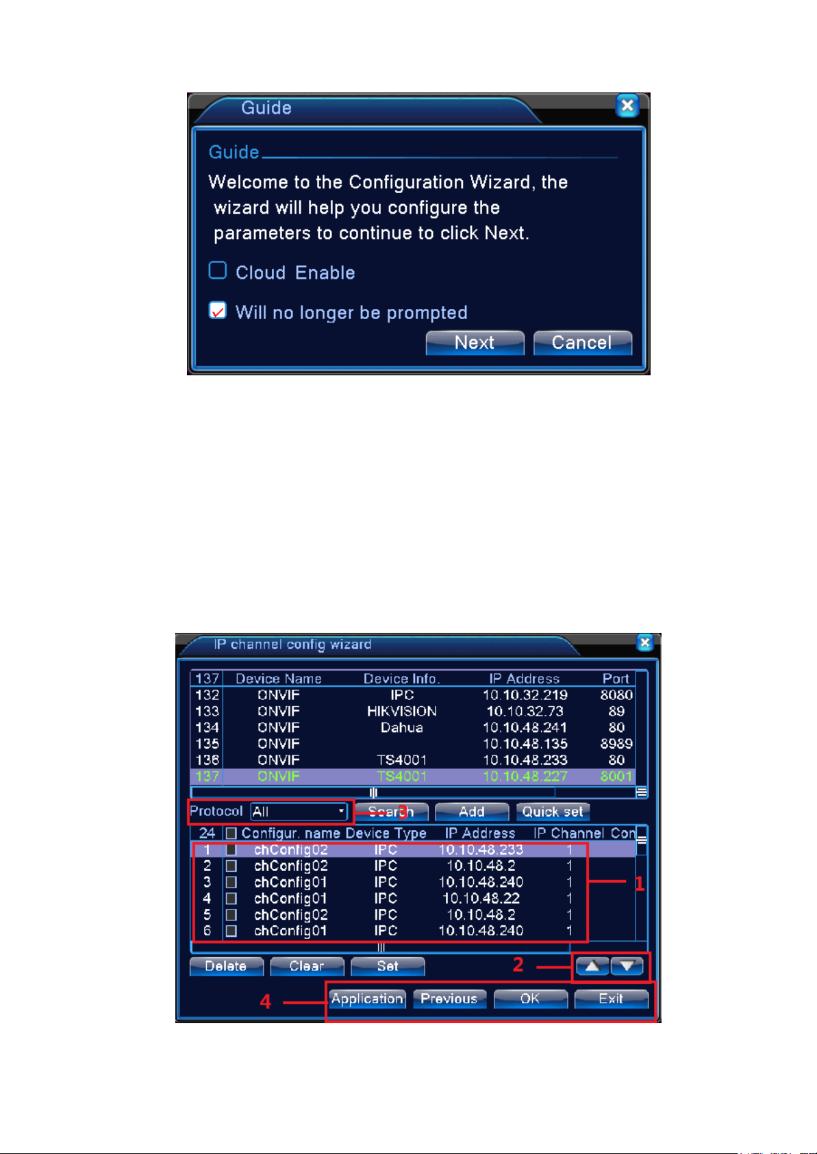
Digital channel configuration wizard:
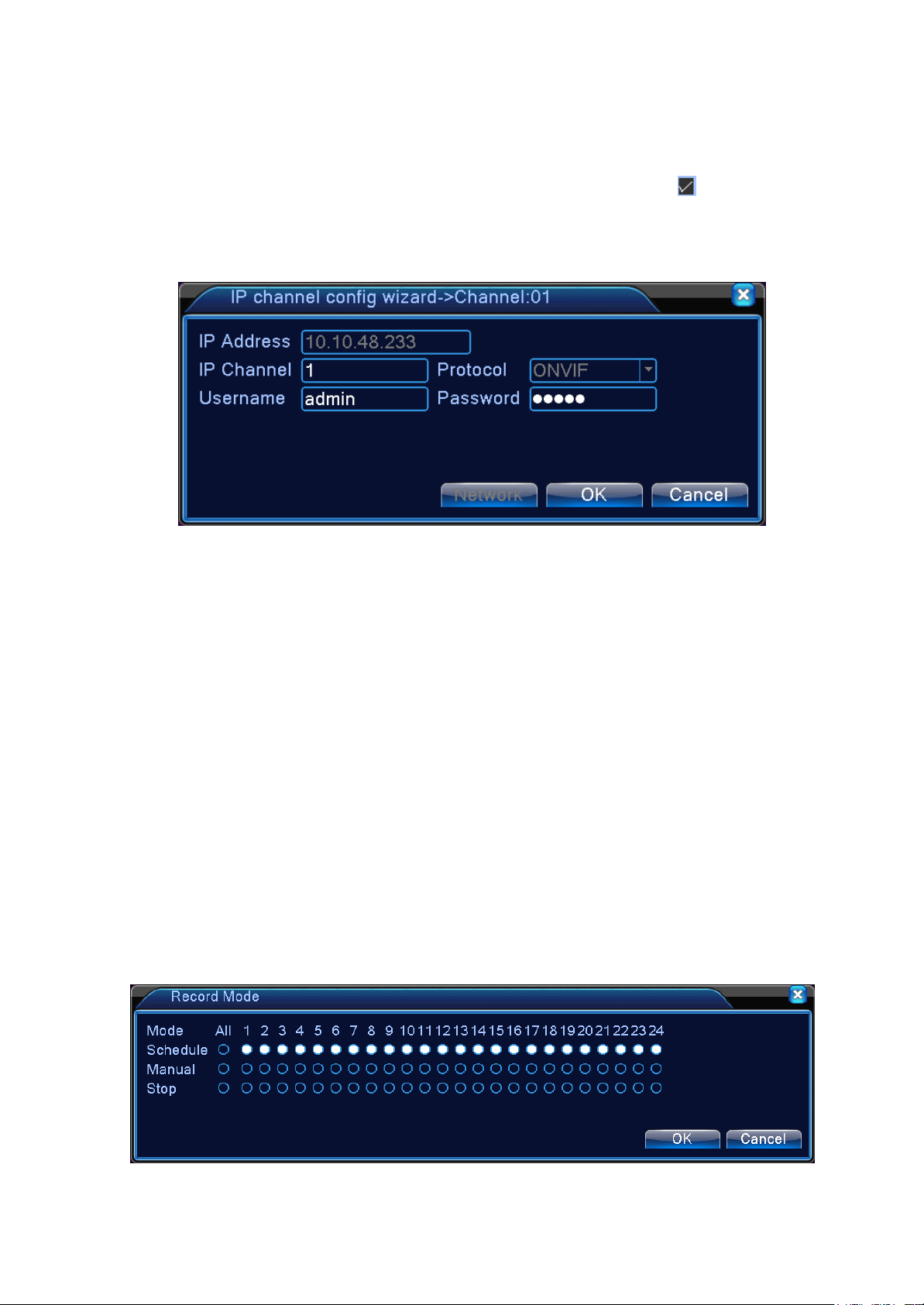
Click on the next step in figure 3.5, the pop-up digital channel configuration wizard, as shown in figure 3.6
can be set up in fast digital channel.
Note: use this feature, all configuration parameters in digital channel will be updated, please be
careful to the configuration which are not for the first time digital channels.
Piture3.6 Digital channel configuration wizard
24 / 91
Label meaning:
① The list of equipment area
The area displays the search equipment. Click on the selected box, the show of said the equipment
is selected, and then double-click the device, the pop-up channel Settings interface, as shown in figure
3.7 for the devices for remote access Settings, user name and password; Click the network Settings
button, the selected equipment for network Settings, including IP, subnet mask, default gateway.
Picture 3.7 Channel Settings interface
②Equipment list
Optional equipment list, which include three kinds of display mode, respectively are showing the selected,
the display for the selected, and showing of all.
③ Rest not selected channel number display area
The remaining not choose channel number is shown here.
④ The position of device button
Click on the equipment list, click on the up and down button, can move the equipment
up and down.
3.5.2 Record Control
Please check current channel status: “●” means it is not in recording status, “●” means it is in
recording status.
You can use desktop shortcut menu or click [main menu]> [recording function]> [recording set]
to enter the recording control interface.
25 / 91
【Schedule】Record according to the configuration.
Picture 3.6 Record Mode
【Manual】Click the all button and the according channel is recording no matter the channel in any
state.
【Stop】Click the stop button and the according channel stops recording no matter the channel in
any state.
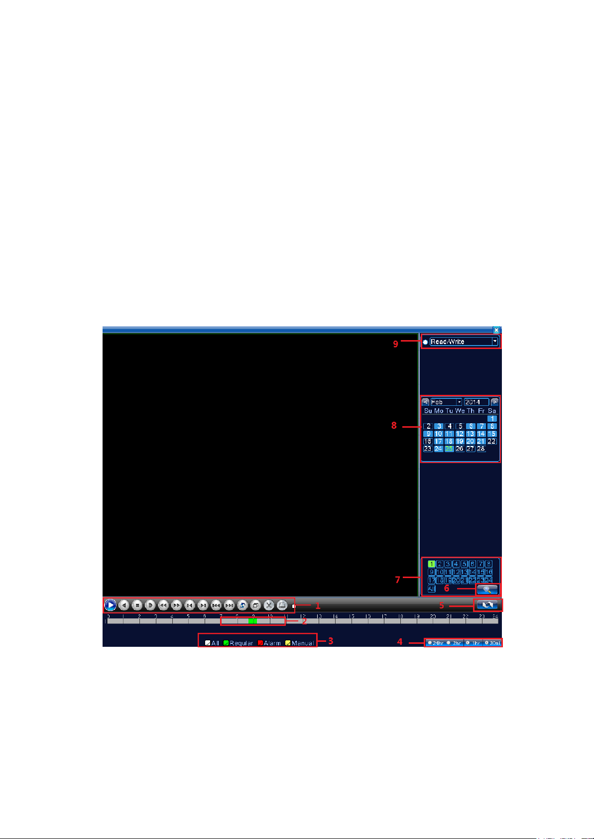
3.5.3 Playback
There are two methods for you to play the video files in the hard disk.
1. In the desktop shortcut menu.
2. Main menu>Record->Playback
Note: The hard disk that saves the video files must be set as read-write or read-only state.(4.5.1).
26 / 91
1. Playback control
2. Time display
3. Video type
4. Time schedule
options
5. Switch by
time/file/mode
6.File search
7.Selected by
channel
8.Selected by time
9. search by storage
location
10.Files information
11. Listed files
12.search by time
13.File backup
Button
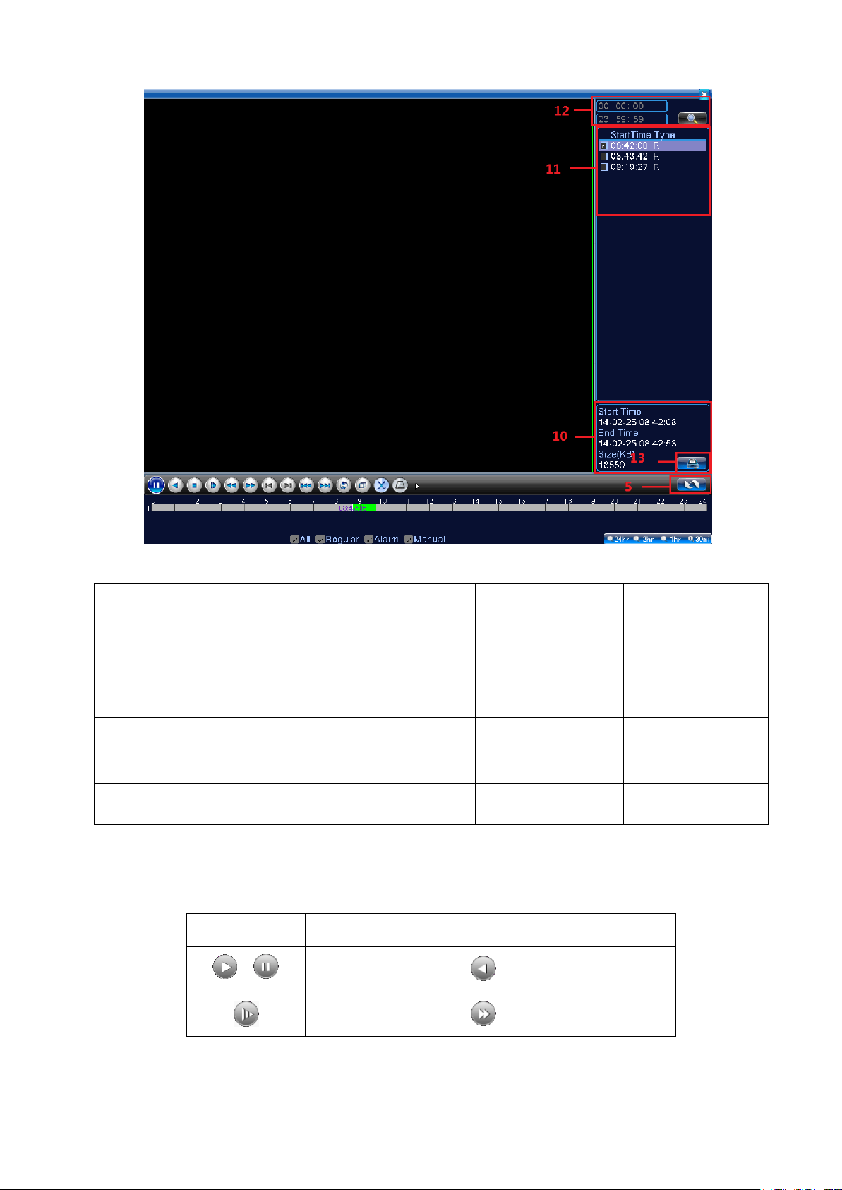
Function
Button Function
/
Play/Pause
Backward play
Slow play
Fast Forward
Picture 3.4 video playback
【Listed files】Look up the listed files that accord with the searching criteria.
【File Attributes】Look up the found file information.
【Playback control】See detail in below chart
27 / 91
Previous frame
Next frame
Round play
Full screen
Stop
/
Begin/end to edit
backup
Picture 3.2 Table Playback control key
Note: play under frame by frame, the playback status should be paused firstly.
【Operation tips】show function of the key that cursor placed.
Special functions:
Accurate playback:Input time (h/m/s) in the time column and then click play button. The
system can operate accurate playback according to the searching time.
Local zoom:When the system is in single-window full-screen playback mode, you can drag your
mouse in the screen to select a section and then left click mouse to realize local zoom. You can right click
mouse to exit.
Note: When current resolution of the channel is over Max resolution, to playback this channel,
will show a Red “X”.
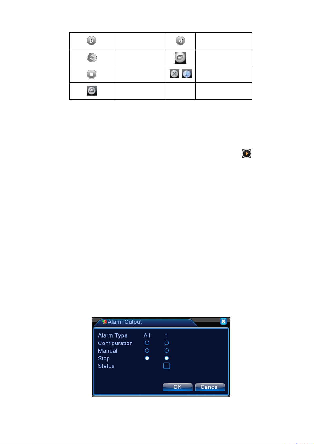
3.5.5 Alarm output
Please check current channel status: “○” means it is not in alarming status, “●” means it is in
alarming status.
You can use desktop shortcut menu or click [main menu]> [alarm function]> [alarm output] to
enter the alarm output interface.
28 / 91
【Configuration】Alarm is on according to the configuration.
Picture 3.10 alarm output
【Manual】Click the all button and the according channel is alarming no matter the channel in any
state.
【Stop】Click the stop button and the according channel stops alarming no matter the channel in any
state.
3.5.6 PTZ control
*PTZ control is a little different between hybrid mode & full digital mode:
Digital channel – the digital channel need link PTZ, the remote device should connect with PTZ
and with protocol correctly set also.
Analog channel – Only when the device is connect with PTZ and configure protocol correctly is
ok.
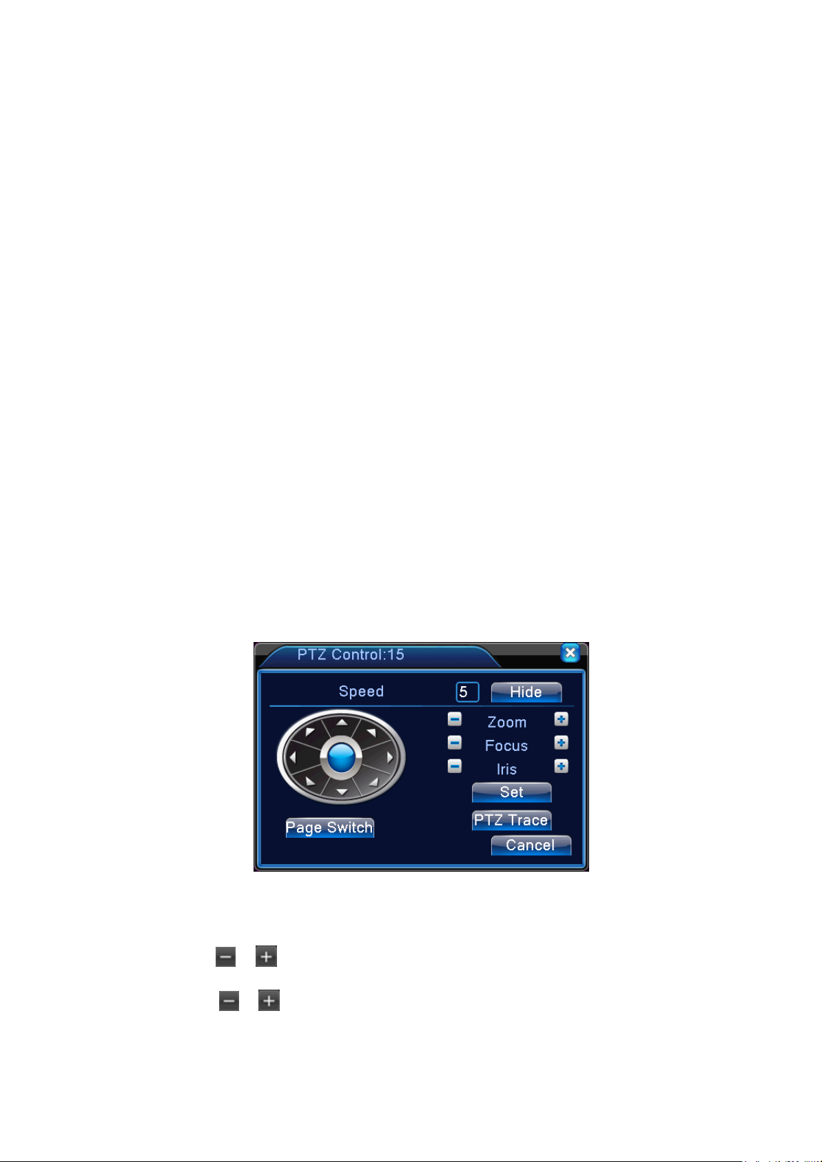
Operation interface is as followed. The functions include: PTZ direction control, step, zoom, focus, iris,
setup operation, patrol between spots, trail patrol, boundary scan, assistant switch, light switch, level
rotation and so on.
Note1. Decoder A(B)line connects with DVR A(B)line. The connection is right.
2. Click [main menu] > [system configuration] >[PTZ setup] to set the PTZ parameters.
3. The PTZ functions are decided by the PTZ protocols.
Picture 3.8 PTZ setup
【Speed】Set the PTZ rotation range. Default range: 1 ~ 8.
【Zoom】Click / button to adjust the zoom multiple of the camera.
【Focus】Click / button to adjust the focus of the camera .

27 / 91
【Iris】Click / button to adjust the iris of the camera.
【Hide】Current interface will be temporarily hidden after click it.
【Direction control】Control the PTZ rotation. 8 directions control is supportive. (4 directions in
Front panel is supportive)
【High speed PTZ】Full-screen show channel image. Left press mouse and control PTZ to rotate
orientation. Left press mouse and then rotate the mouse to adjust the zoom multiple of the camera.
【Set】Enter the function operation menu.
【Page switch】Switch between different pages.
Special functions:
1. Preset
Set a location for the preset, calls the preset points, PTZ automatically turns to the setting
position
1)Preset option
Set a location for the preset, procedure is as follows:
Step1: in Picture 3.10, click the Direction button will turn into preset position, click the Settings
button to enter Picture 3.11.
Step 2: click the Preset button, then write the preset points in the input blank,
Step 3: click Settings button, return the Picture 3.10 Complete setup, that is the preset points and
preset position corresponds.
Clear Preset:Input preset points, click Remove button, remove the preset.
Preset button
2)Preset Point Calls
Picture 3.12 Preset Settings
Preset point input blank

28 / 91
In Picture 3.10, click Page Shift button, enter PTZ control interface as shown in Picture 3.12. In
the input blank, write the preset points, then click Preset button, PTZ turn to the corresponding
preset point.
Value input blank
2. Cruise between Points
Multiple preset points connected cruise lines, call cruise between points, the PTZ run around on
the line
1)Cruise between Points Settings
Cruise lines is connected by multiple preset points, setting procedure is as follows:
Step1: In Picture 3.10, the Direction key will turn PTZ to designated location, click Settings
Picture 3.13 PTZ Control
button to enter Picture 3.13,
Step 2: click Cruise buttons, the write proper value into the Cruise Line and Preset Points blank,
then click Add Preset Points button, complete setting (also can add and delete cruise line which has
been set up)
Step 3: repeat step1 and step2, until set out all the preset designated cruise lines。
Remove Preset:Please input preset value in the blank, click Remove Preset button, then
remove the preset points.
Remove Cruise Line Input the number of cruise line, click Remove Cruise Lines button, then
remove the cruise lines set.

29 / 91
Preset Points Blank
Cruise Button
Time interval
Picture 3.14 Cruise Between Points Settings
2)The Calls of Cruise between Points
In Picture 3.10, click Page Shift button, enter PTZ control menu as shown in Picture 3.12. Please
input the number of cruise in the value blank, then click Cruise between Points button, PTZ begins to work
on the cruise line. Click Stop button to stop cruise.
Cruise Line Blank
3. Scan
PTZ also can work on the preset scan line repeatedly.
1)Scan setup
Setting steps:
Step1: In Picture 3.10, click Setup button ,enter Picture 3.14;
Step2: Click Scan button, the input proper value in the scan value blank;
Step3: Click Start button, enter Picture3.10 , here you can set the following items:
Zoom, Focus, Aperture, Direction and so on. Click Setup button to go bac k Picture 3.14
Step4: Click End button to complete setup. Click the right button of the mouse to exit.
Scan Button
Scan value blank
Picture 3.15 Scan Setup

30 / 91
2)Scan Calls
In Picture 3.10, click Page Shift button, then enter PTZ control menu as shown in Picture 3.12.
Please input the number of scan in the value blank, then click Scan button, PTZ begins to work on
the scan line. Click Stop button to stop.
4. Boundary Scan
In a horizontal line, set up a line, call scan, PZT repeat operation according to the route
1)Boundary Scan setup
Set a period of horizontal curve for PTZ search path the steps are as follows:
Step1:In Picture 3.10, click Direction butt on to turn the PTZ to preset direction, then click Setup
button enter Picture 3.15, select the left boundary, return to Picture 3.10;
Step2:Please click direction arrows to adjust PTZ direction, click Setup button enter Picture3.15,
then select the right boundary ,return to Picture 3.10;
Step3: Complete setup, that is the position of left and right boundary
Note: when the left and right scan in one horizontal, the PTZ will cycle rotate from left scan
along the reverse direction to the right scan.
When the left and right scan not in the same horizontal, the PTZ will regard the end of horizontal line
which connect to left scan as right scan cycle rotate from left scan along the reverse direction to the right
scan.
Left/Right scan setting button
Line scan button border
2)Boundary Scan Calls
In Picture 3.10, click Page Shift button, then enter PTZ control menu as shown in Picture 3.12.
Please input the number of scan in the value blank, then click Scan button, PTZ begins to work on
Picture 3.16 Boundary Scan Setup

31 / 91
the scan line . Click Stop button to stop.
5. Horizontal Rotating
Click Horizontally Rotating button, PTZ begins to rotate horizontally (relative to the original position
of the camera). Click the Stop button to stop.
6. Rotate
Click on horizontal Rotating button, PTZ turn around.
7. Reset
PTZ restart, all the data clears to 0.
8. Page Shift
In Picture 3.12, click Page Shift button into Picture3.16, setting auxiliary function. Auxiliary
number corresponding to auxiliary switch on the decoder.
Picture 3.17 Auxiliary Function Control
【Intuitive Auxiliary Operation】 choose auxiliary equipment, select Open or Close button,
switch control;
【 Auxiliary Number 】 The operation of corresponding auxiliary switch according to PTZ
agreement;
【Page Shift】 In Picture 3.16,click Page Shift button enter the Picture 3.17 PTZ Main Menu , the
menu itself can be control by the menu control buttons
3.5.7 Color setting
*Color config: analog channel can config its own color, digital channel can config front-end image
(only NETIP-conformed device is supported, ONVIF-conformed device is not supported)
Set the selective image parameters (current channel for single window display and cursor place for
multi-window display). You can use the desktop shortcut menu and enter the interface. The image

32 / 91
parameters include: tonality, brightness, contrast, saturation. You can set different parameters at different
time sections.
Picture 3.18 Color Setting
3.5.8 Output Adjust
*Hybrid mode is with black margin vertical & horizontal, while full digital mode without.
Adjust TV output area parameters. You can use the desktop shortcut menu or enter [main menu]>
[management tools]> [Output adjust].
Picture 3.15 Output Adjust

33 / 91
3.5.9 Logout
Main menu
Sub menu
Function
Record
Config
Set the recording configuration, recording type, recording time section
playback
Set recording search, recording play, video file storage
backup
Detect backup device, format device, back the selective files
Motion
detection
Set motion detect alarm channel, sensitivity, area, linkage parameters:
defending time section, alarm output, screen hint, recording, screen
shot, PTZ, patrol, buzz, email ,PMS and FTP upload
Logout, shut down the system or reboot up. You can use the desktop shortcut menu or enter [main
menu].
Picture 3.16 Logout/ Shutdown/Reboot the system
【logout】Quit the menu. Offer password next entrance.
【shut down】Quit the system. Turn off the power supply.
When press the shut down button, there is schedule hint. After three seconds, the
system is shut down. Cancel midway is of no effect.
【reboot】Quit the system. Reboot up the system.
3.5.10Full screen(exit full screen)
Can choose full screen and not full screen according to demand
4 Main menu
4.1 Main menu navigation

34 / 91
Alarm
Video
blind
Set camera mask alarm channel, sensitivity, linkage parameters:
defending time section, alarm output, screen hint, recording, screen
shot , PTZ, patrol, buzz, email ,PMS and FTP upload
Video
loss
Set video loss alarm channel, linkage parameters: defending time
section, alarm output, screen hint, recording, screen shot , PTZ, patrol,
buzz, email ,PMS and FTP upload
Alarm
input
Set alarm input channel, equipment type, linkage parameters:
defending time section, alarm output, screen hint, recording, screen
shot , PTZ, patrol, buzz, email ,PMS and FTP upload
Note:T series have no this function
Alarm output
Set alarm mode: configuration, manual, shut down
Note:T series have no this function
Exception
handling
No HDD, HDD error, HDD capacity not enough, network cut, IP
Conflict, linkage parameters, screen hint or buzz.
Intelligent
analysis
Set algorithm rule: trajectory display, sensitivity, minimum pixel, alert
mode, and setting linkage parameters: period, alarm output, the screen
prompt, record, PTZ, tour, buzzer, EMAIL, FTP upload.
Note: 6000 series support this function
General
configuration
Set system time, data format, language, hard disk full time operation,
machine number, video format, output mode, summertime, stay time
System
configuration
Network
configuration
Set basic network parameters, DHCP and DNS parameters, network
high speed download
Net Service
PPPOE, NTP, Email, IP purview, DDNS parameter, PMS
Output mode
Set the channel names, preview icon of the status, transparency, and
VGA (HDMI) resolution is preferred
RS485
Device
Set serial port function, baud rate, date bit, stop bit, check
Note:Full digital mode shows : RS485 Device
Serial port
Configuration
(RS232)
Set serial port function, baud rate, date bit, stop bit, check
Note:T series have no this function

35 / 91
Tour
Set patrol mode and interval time
Channel
management
Set the channel mode, check channel status, and set the parameter of
digital channels
Management
tools
Hard disk
management
Set appointed hard disk as read-write disc, read-only disc or redundant
disc, clear data, resume date and so on
User
management
Modify user, team or password. Add user or team. Delete user or team.
Online user
Break the connection with the already login user. Lock the account
after break until booting up again.
Output adjust
Adjust upside, downside, nearside, starboard distance, black margin
vertical & horizontal
Note:only analog channel have black margin vertical & horizontal
Automatic
maintenance
Set automatic reboot system and automatic deleting files.
Restore
Resume setup state: common setup, code setup, recording setup,
alarm setup, network setup, network service, preview playback, serial
port setup, user management
Upgrade
upgrade with external device(like USB)
Device Info
device hardware configuration and message
Import/Export
Export the device's log or configuration to external device (like USB
flash disk); Input the configuration with external device (like USB
flash disk).
System
information
Hard disk
information
Display hard disk capability and recording time
BPS
Display code stream information
Log
information
Clear all log information according to the log video and time
Edition
information
Display edition information

36 / 91
Shut down Logout, shut down or reboot
4.2 Record
Operations related to record, including: Record, Playback, Backup, Screen shot (only Hybrid
mode and full analog have)
4.2.1 Record Configuration
Set the recording parameters in the surveillance channel. The system is set 24 hours consecutive
recording in the first startup. You can enter [main menu]> [recording function]> [recording setup] to set.
Note: There is at least one read-write hard disk. (Refer to chapter 4.5.1)
Picture 4.1 Record Configuration
【Channel】Choose the corresponding channel number to set the channel. Choose the all option to
set the entire channels.
【Redundancy】Choose the redundancy function option to implement the file double backup function.
Double backup is writing the video files in two hard disks. When you do the double backup, make
sure that there are two hard disks installed. One is read-write disk and the other is redundant disk.
(refer to 4.5.1)
【Length】Set the time length of each video file. 60minutes is default value.
【Pre-Record】Record 1-30 seconds before the action. (time length is decided by the code stream)
【Record mode】Set video state: schedule, manual or stop.

37 / 91
Schedule: Record according to the set video ty pe (common, detection and alarm) and time
section.
Manual: Click the button and the according channel is recording no matter the channel in
any state.
Stop: Click the stop button and the according channel stops recording no matter the
channel in any state.
【Period】Set the time section of common recording, The recording will start only in the set range.
【Record type】Set recording type: regular, detection or alarm.
Regular: Perform the regular recording in the set time section. The video file type is “R”.
Detection: Trigger the “motion detect”, “camera mask” or “video loss” signal. When above
alarm is set as opening recording, the “detection recording” state is on. The video file type is
“M”.
Alarm: Trigger the external alarm signal in the set time section. When above alarm is set
as opening recording, the “detection recording” state is on. The video file type is “A”.
Note: Refer to chapter 4.3 to set corresponding alarm function.
4.2.1Playback
Refer to chapter 3.5.2.
4.2.2 Backup
You can backup the video files to external storage through setup.
Note:The storage must be installed before the file backup. If the backup is terminated, the
already backup can playback individually.

38 / 91
【Detect】Detect the storage connected with the DVR such as hard disk or universal disk.
【Backup】Click backup button and the dialog box is popped up. You can choose the backup file
according to the type, channel and time.
Remove:Clear the file information.
Add:Show the file information satisfying the set file attributes.
Picture 4.2 Backup
Picture 4.3 Backup

39 / 91
Backup format configurate the backup file format, according to require, can choose
Start/pause:Click the play button to start the backup and click the pause button to stop the
backup.
Note:During backup you can exit the page layout to carry out other functions.
【Burning】the file will be burned synchronously after click it.
【Erase】Choose the file to delete and click erasure to delete the file.
【Stop】Stop the backup.
4.3 Alarm Function
Alarm functions include: motion detect, video blind, video loss, alarm input and alarm output,
abnormality, intelligent analysis.
4.3.1 Motion Detect
When system detects the motion signal that reaches the set sensitivity, the motion detect alarm is on
and the linkage function is turned on.
Note: "Advanced" button is the same as right click.
*Motion detect function is different between Hybr id mode & Full digital mode:
Digital channel: not only to enable motion detect function at local side, but also to enable the
remote device that was connected. When remote device detect motion movement, local side will
start alarm recording, otherwise this function is not enable.
Hybrid mode: only need to enable motion detect function at local side.

40 / 91
【Channel】Choose the set motion detect channel.
【Enable】■ means that the motion detect function is on.
【Period】Trigger the motion detect signal in the set time section. You can set according to week or
Pic 4.4 Motion Detect
set uniformly. Each day is divided into four time sections.■ means the set valid.
【Interval】 Only one alarm signal is turned on even there are several motion detect signals in the set
Picture 4.5 set the time section
interval.
【Alarm output】Start the external equipment of corresponding linkage alarm when the motion

41 / 91
detect alarm is turned on.
【Delay】Delay a few moments and stop when the alarm state is turned off. The range is 10~300
seconds.
【Record channel】Choose the recording channel (multiple option supportive). Trigger the video
signal when the alarm is turned on.
Note: Set in the [recording setup] and perform the linkage recording. Start detecting video files
in the corresponding time section.
【Tour】■ means that the selective channel is single window alternate patrol preview. The interval is
set in the [Main Menu]>[System] > [Tour].
【PTZ Activation】Set the PTZ activation when the alarm is turned on.
*Hybrid mode, PTZ link to the related PTZ information of analog channel, While digital
channel model, the PTZ is link to the related PTZ information on the remote device connected.
Note:to link PTZ, need go [Shortcut menu]->[PTZ control] to set preset point, cruise between
points & interval time, etc.
Picture 4.6 PTZ Activation under hybrid mode
【Delay】When alarm is over, recording will last some seconds (10~300sec), then stop.
【Show message】Pop the alarm information dialog box in the local host computer screen.
【Send EMAIL】■ means sending an email to user when the alarm is turned on.
Note: Set in the [NetService] and send email.

42 / 91
【FTP upload】to tick it, the video & picture of related record channel & snapshot channel will be
uploaded to assigned position.
Note:FTP upload need be set at [Netservice]
【Buzz】When alarm happens, device will come out with buzz.
4.3.2 Video Blind
When the video image is influenced by the environment such as bad brightness or reaching the set
sensitivity parameter, the camera mask function is turned on and the linkage function is turned on.
*Same as motion detect function, video blind is different between Hybrid mode & Full digital mode:
Digital channel: not only to enable video blind function at local side, but also to enable the remote
device that was connected. when remote device with video blind, local side will start alarm
recording, otherwise this function is not enable.
Hybrid mode: only need to enable video loss function at local side.
Note: "Advanced" button is the same as right click.
Pic 4.7 Video blind
Set method: refer to chapter 4.3.1. Motion detect
4.3.3 Video Loss
When the equipment can not obtain the channel video signal, the video loss alarm is turned on and

43 / 91
the linkage function is turned on.
*Same as motion detect function, video loss is different between Hybrid mode & Full digital
mode:
Digital channel: not only to enable video loss function at local side, but also to enable the remote
device that was connected. When remote device with video loss, local side will start alarm
recording, otherwise this function is not enable.
Hybrid mode: only need to enable video loss function at local side.
Note: "Advanced" button is the same as right click.
Pic 4.8 Video loss
Set method: refer to chapter 4.3.1. Motion detect
4.3.4 Alarm input
When the equipment obtains the external alarm signal, the alarm function is turned on.
*Alarm input is the same between hybrid mode & full digital mode, function enable, when it
was set normal, only need to connect alarm sensor at alarm input port on local side, the alarm
information is occurring, and will link to related setting functions at the same time
Note: "Advanced" button is the same as right click.

44 / 91
Pic 4.9 Alarm input
Set method: refer to chapter 4.3.1. Motion detect
4.3.5 Alarm output
Refer to chapter 3.5.4.
4.3.6 Abnormal
Analyzing and inspecting current software and hardware of the device: When some abnormal events
happen, the device will make a relative answer such as show message and buzzer.

45 / 91
Picture 4.10 Abnormal
【Event Type】 selecting abnormity you want to inspect, No Storage, Storage
Error,Storage No Space,Net Disconnection and IP Conflict.
【Enable】Select it to make sure abnormal function workable
【Show message】Automatically alarm cue dialog box come out of the main screen
【Buzzer】Device will have one long nosie “di” while alarm is happening
4.4 System setup
Set the system parameters such as General, Encode (under Hybrid/full analog mode)
Network, Net service, GUI display, PTZ configure/RS485 device, RS232, Tour setup, Spot and
digital.

46 / 91
4.4.1 General
Picture 4.11 General setup
【System ti me】Set the system data and time.
【Date format】Choose the data format: YMD, MDY, DMY.
【Date Separator】Choose list separator of the data format.
【Time Format】Choose time format: 24-hour or 12-hour.
【Language】support 29 language at present: Arabic, Czech, English, Finnish, Greek, Indonesian,
Italian, Japanese, Portuguese, Russian, Thai, T- Chinese, S-Chinese, Turkish, Brazilian, Bulgarian,
Farsi, French, German, Hebrew, Hungarian, Polish, Romanian, Spanish, Swedish, Vietnamese
【HDD full】Choose stop record: Stop recording when the hard disk is full.
Choose overwrite: Cover the earliest recording files and continue recording when the
hard disk is full.
【DVR No.】Only when the address button in the remote controller and the corresponding DVR
number is matched, the remote operation is valid.
【Video Standard】PAL or NTSC.
【Auto Logout】Set the latency time in 0-60. 0 means no latency time.
【Machine Name】Can setting the device's name.

47 / 91
【DST】Choose the summer time option and pop the dialog box as followed.
4.4.2 Network setup
Picture 4.12 DST (week)
Picture 4.13 DST (date)
Picture4.14 Network
【Net Card】You can choose cable network card or wireless network card.

48 / 91
【DHCP Enable】Obtain IP address automatically (not suggested)
Note:DHCP server is preinstalled.
【IP address】Set the IP address. Default: 192.168.1.10.
【Subnet mask】Set the subnet mask code. Default: 255.255.255.0.
【Gateway】Set the default gateway. Default: 192.168.1.1.
【DNS setup】Domain Name Server. It translates the domain na me into IP address. The IP address
is offered by network provider. The address must be set and reboot then it works.
【Media port】Default: 34567.
【HTTP port】Default: 80.
【HS Download】
【Transfer Policy】There are three strategies: self-adaption, image quality precedence and fluency
precedence. The code stream will adjust according to the setup. Self-adaption is the tradeoff between
the image quality precedence and fluency precedence. Fluency precedence and self-adaption are
valid only when the assistant code stream is turned on. Otherwise image quality precedence is valid.
4.4.3 Net Service
Choose the network service option and click the set button to configure the advanced network functions
or double click the service button to configure the pa rameters.
Picture 4.15 NetService

49 / 91
【PPPoE setup】
Picture4.16 PPPOE
Enable:Reverse■ means choose,setting can become effective.
Input the user name and password that ISP(Internet service provider) provides. After saving it
reboot up your system. Then the DVR will build a network connection based on PPPoE. The IP address
will change into dynamic IP address after above operation is well done.
Operation:After PPPoE dialing successfully look up the IP address in the [IP address] and obtain the
current IP address. Then use this IP address to visit the DVR through user port.
【NTP setup】
Picture 4.17 NTP
The NTP server must be installed in the PC.
Enable:Reverse■mean choose,setting can become effective.
Host computer IP: Input the IP address installed NTP server.
Port:Default: 123. You can set the port according to NTP server.
Time zone: London GMT+0 Berlin GMT +1 Cairo GMT +2 Moscow GMT +3 New Delhi GMT
+5 Bangkok GMT +7 Hongkong Beijing GMT +8 Tokyo GMT +9 Sydney GMT +10 Hawaii

50 / 91
GMT-10 Alaska GMT-9 Pacific time GMT-8 American mountain time GMT-7 American mid time
GMT-6 American eastern time GMT-5 Atlantic time GMT-4 Brazil GMT-3 Atlantic mid time GMT-2.
Update Period:The same with the NTP server check interval. Default: 10minutes.
【EMAIL setup】
If the alarm is turned on or the alarm linkage photos are taken, send an email about the alarm
information and the photos to appointed address.
Picture 4.18 EMAIL
SMTP server:Email server address. It could be an IP address or domain name. Domain name can
be translated only it is the correct DNS configuration.
Port:Email server port number.
SSL:Decide whether using Secure Socket Layer protocol to login.
User Name:Apply the email server user name.
Password:Input the password corresponding to the user.
Sender:Set the email sender address.
Receiver:Send the email to appointed receivers when the alarm is turned on. You can set three
receivers at most.
Title:You can set as you wish.
【IP Filter setup】
When choosing the white list, only the listed IP address can connect the DVR. The 64 IP addressed

51 / 91
are supportive in the list.
When choosing the black list, the listed IP address can not connect the DVR. The 64 IP addressed
are supportive in the list.
You can delete the set IP address by √ in the options.
Note:When the same IP address is in the white and black list at the same time, the black list precedence
is higher.
Picture 4.19 IP FILTER
【DDNS】
Picture 4.20 DDNS setup
It is the abbreviation of dynamic domain name server.
Local domain name:Provide the domain name registered by DDNS.
User name:Provide the account registered by DDNS.

52 / 91
When the DDNS is successfully configured and start, you can connect the domain name in the IE
Password:Provide the password registered by DDNS.
address column to visit.
Note:The DNS setup must be configured correctly in the network setup.
【FTP setup】
FTP is available only when alarm happens, or alarm activates record and snapshot, it will upload
related record and snapshot pictures to FTP server.
Picture 4.21 FTP setup
【Enable】Click Enable, then all settings will be available
【Server IP】IP address for FTP server
【Port】Domain Port of FTP, default 21
【User Name】User name of FTP
【Password】Password of user
【Anonymous】:enable anonymous, no need setting user name and password
【Max File Length】Max length for upload files at every packed, default 128M
【Dir Name】:The directory of upload file.
Note: The user should be with authority to upload files.
【ARSP】
Startup DDNS server to add devices and manage it in the DDNS server

53 / 91
【Type】choose "DNS"
Picture 4.22 ARSP
【Enable】 ■ means it is chosen
【Sever IP]】IP address of DDNS server
【Port】 Port No. of device, related DDNS server listen port
【User name】 the user name that device can log in DDNS server
【Password】 the password related to the user name.
【Refresh cycle】Time interval between device and DDNS when chynchronously.
Note: Please set up server before using DDNS.
【Alarm center】
When alarm occurring, report alarm information to alarm server.
Pic: 4.23 alarm server setting
【Protocol type】GENERAL
【Enable】To tick it means enable.

54 / 91
【Server Name】IP address of Alarm Server
【Port】Device Port No.
【Alarm Report】Tick it means to report alarm information to server.
【Log Report】Tick it, means to report log to server.
【Wireless Config】
ADSL through 3G net card,use CMS to visit and config the device
Picture 4.24 Wireless Config
【Enable】Choose Enable to make all settings available
【Type】Dial type,default AUTO
【Wireless AP】3G access point
【Dial Number】3G Dial Number
【User Name】User name of 3G
【Password】Password of dial user
【IP Address】IP address, got from dial
Note:parts of A series and T series don't support this function.
【UPNP】
UPNP protocol is to realize auto port forwarding on router, precondition of using this function is to
make sure the UPNP function of router is enabled.

55 / 91
【Enable】Choose Enable to make sure all UPNP settings available
【HTTP】Route will automatically distribute HTTP port for the device, when IE viewing, it need this
port
【TCP】Router will automatically distribute TCP port for the device,when monitoring via CMS,it need
this port.
【Mobile Port】Router will automatically distribute Mobile Port for the device, when mobile monitor,
it need this port.
【WIFI】
DVR connect to wireless router via WIFI module, then to visit it through IP address, the precondition
of using this function is to make sure the DVR have connected with WIFI modern.
Picture 4.26 UPNP
Pic 4.27 WIFI configure

56 / 91
【Search】:click【search】to search all the available wireless device in current range.
【enable】:tick it to enable firstly, then go for further setting.
【auto obtain IP address】:tick it to enable, device will auto obtain a WIFI IP.
【SSID】:wireless LAN name, auto match to the wireless device u connected.
【Password】:wireless network password of router;
【IP address】: to set the IP address of device, default is 192.168.1.12
【subnet mask】: set subnet mask of device, default is 255.255.255.0
【gateway】:set gateway of device, default is 192.168.1.1
【RTSP】
To do surveillance via cross-browser (Safari, Firefox, Google chrome ) and VLC software. This
function only for monitor but can not control the device.
Pic 4.28RTSP setting
【Enable】:■ means enable, tick it firstly before setting.
【Port】:the default port is 554
【CLOUD】
Check the cloud services, male cloud service is enabled, the user can visit http://www.xmeye.net
【Enable】 Select it to make sure abnormal function workable
【PMS】
Enable this function, at the same time open the function in the mobile end, exit the application, when
the alarm occurs, check the cell phone to report, will send information to cell phones.

57 / 91
【Enable】 Select it to make sure abnormal function workable
【Server Name】 default:push.umeye.cn
【Port】 Equipment set the default port is 80
4.4.4 Output mode
Configure the video output parameters including the front output mode and encode output mode.
Front output:In the local preview mode include: channel title, time display, channel display, record
status, alarm status, transparency and region cover.
Encode output:In the network surveillance and video file mode include: channel title, time display,
channel display, record status, alarm status, transparency and region cover.
*Remark: Only 6000 series product support preview resolution - 1920*1280(1080P)
Pic 4.31 output mode
【Channel Title】Click the channel name modify button and enter the channel name menu. Modify

58 / 91
the channel name. The 16 Chinese characters and 25 letters are supportive.
【Time Display】means the selective state. Display the system data and time in the surveillance
window.
【 Channel display 】 means the selective state. Display the system channel number in the
surveillance window.
【Record Status】means the selective state. Display the system recording status in the surveillance
window.
【Alarm Status】means the selective state. Display the system alarm status in the surveillance
window.
【Transparency】Choose the background image transparency. The range is 128~255.
【Resolution】set display resolution.
【Channel】Choose the set code output channel number.
【Region Cover】means the selective state. Click the cover area button and enter the corresponding
channel window. You can cover the arbitrary using mouse. (Black region is for output)
【Time display】&【Channel display】 set the display position of channel title and time title.
*the channel no., region cover, time title and channel title setting function exist at output
mode only when the device is under hybrid(HVR) mode or full analog (DVR) mode.
4.4.5 Serial port settings
【Serial Port Function】Common serial port is used to debug and update program or set up specific
Pic 4.33 serial port setting

59 / 91
serial port.
【Baud rate】Choose the corresponding baud rate length.
【Data bits】Include 5-8 options.
【Stop bits】Include 2 options.
【Parity】Include odd, even, mark, space, default is none.
4.4.6 Tour
Set the patrol display. means that the tour mode is enable. You can choose the single-view,
four-view, six-view of single mode tour or hybrid mode tour.
【interval】Set the patrol switch interval. The set range is 5-120 seconds.
【alarm tour】set the interval to shift alarm tour, range is 5-120 seconds, choose return when alarm
Pic 4.34 tour configure
ends, when alarm link to tour, system will auto shift to six-view after alarm finished.
Remark:at preview mode, click upper right icon / can turn on / off tour( mean turn on,
mean turn off.
4.4.7 Channel manage
*Remark:only HVR and 6000 series product support this function.

60 / 91
Digital manage including digital channel, channel status, and channel mode (Remark: there is only
analog mode if device is under full analog mode):
Channel manage page under Hybrid (HVR) mode / full digital(NVR) mode
Pic 4.35 channel manage interface
Digital channel:
Single link page of digital channel

61 / 91
Multi-linkage page of Digital channel
Pic 4.36 digital channel interface
【Channel】select channel title
【Enable】Open digital channel, tick enable, then can do related settings
【Time Synchronization】Tick it means the time of this channel and device is the same.
【Connection Mode】can be singe connect or multi-ink, multi-link modes can connect to several
devices, device will be tour displayed one by one, tour interval can be set, no less then 10s;
【Delete】If the user want to change device, select the existing device, click delete will be ok.
【Add】click add will come out below page to add new device

62 / 91
Pic 4.37 remote channel configure page
【Configure Name】device is with default configure title, user can revise it if necessary;
【Device Type】3 types: IPC、DVR、HVR,user can choose as what you like, default is IPC;
【Protocol】Default is TCP
【Remote channel】User can input remote channel title from the device that you want to connect
remotely
【Stream】Default is main stream, do not support extra-stream at present;
【Device address】IP address of device.
【Port】Default is 34567
【User name】Default is admin
Remark: click 【search】will show all the devices that searched out, user can choose any of the
device that you like.

63 / 91
Pic 4.38 the device list searched under remote channel setting
Channel Status:
channel status is to show the status of all the digital channel When there is what existing, status
including Max Resolution, This Resolution, Connection Status.
For example: The channel status for 16+8 mode is as below:

64 / 91
When a channel is added with device but it is not enable, you will see as below:
Channel status interface under full digital(NVR) mode (One of the channel without device)

65 / 91
Remark: when the current resolution is over the max resolution that the channel supported, then a
red “X” will be shown on the preview image, for example: Under full digital channel mode, Max
resolution of channel 3 is D1, if it was connected to a device with resolution over D1 ( such as
960H), you will see below pic:
Channel mode:

66 / 91
Remark: this series of product with full analog channel mode, hybrid mode and full digital mode,
and different model with different channel mode, user can shift the mode freely if necessary.
4.5 Advanced
Manage tools menu including: HDD manage, account manage, online user, output adjust, auto maintain,
upgrade.
4.5.1 HDD Manage
Configure and manage the hard disk. The menu displays current hard disk information: hard disk
number, input port, type, status and overall capability. The operation include: setup the write-read disk,
read-only disk, redundant disk, hard disk format, resume default. Choose the hard disk and click the right
function button to execute.
Note:Read/Write Disk: The equipment can write or read data.
Read-only Disk: The equipment can read data but can not write data.
Redundant Disk: Double backup the video files in the write-read disk.

67 / 91
Pic 4.40 HDD manage
4.5.2 Account
Manage the user purview.
Note:1. The character length is 8 bytes at most for the following user and user team name. The blank
ahead or behind the character string is invalid. The middle blank in the character string is valid.
Legal characters include: letter, number, underline, subtraction sign, dot.
2. There is no limit in the user and user group. You can add or delete the user group according to user
definition. The factory setup include: user\admin. You can set the team as you wish. The user can
appoint the purview in the group.
3. The user management include: group/ user. The group and user name can not be the same. Each
user only belongs to one group.

68 / 91
Pic 4.41 account management
【Modify User】Modify the existed user attribute.
【Modify Group】Modify the existed team attribute.
【Modify Password】Modify the user password. You can set 1-6 bit password. The blank ahead or
behind the char string is invalid. The middle blank in the char string is valid.
Note:The user who possess the user control purview can modify his/her own or other users
password
Pic 4.42 modify password
【Add user】Add a user in the group and set the user purview. Enter the menu interface and input
the user name and password. Choose the team and choose whether cover using the user. Cover using
means that the account can be used by multiple users at the same time.
Once choose the team the user purview is the subclass of the team.

69 / 91
We recommend that the common user’s purview is lower than the advanced user.
Pic 4.43 Add User
【Add Group】Add a user group and set the purview. There are 33 different purviews: shut down the
equipment, real time surveillance, playback, record setting, video backup and so on.
Pic 4.44 add group
【Delete User】Delete the current user. Choose the user and click delete user button.
【Delete Group】Delete the current group. Choose the group and click delete group button.

70 / 91
Pic 4.45 Delete Group
4.5.3 Online user
To check the information of network user that connected with local device, also can tick the selected
user to break up connection, (make √ at the box) then the user will be frozen after connection stopped, and
will not log in until device reboot.
Pic 4.46 online user
4.5.4 Output adjust
Refer to chapter 3.5.8 .

71 / 91
4.5.5 Auto Maintain
The user can set the time to auto reboot and auto delete file.
Picture 4.47 Auto maintain
4.5.6 Restore
The system restore to the default. You can choose the items according to the menu.
Pic 4.54 restore to default

72 / 91
4.5.7 Upgrade
Pic 4.49 grade
【Upgrade】choose USB interface.
【Upgrade file】choose the upgrade file.
4.5.8 Device Info
Provide device interface info like audio in, alarm in/out to be conveniently used for user.
Pic 4.50 device info
4.5.9 Import / Export
Users can export the log info and the configure file from device to connected flash stick, and also can
import related configure file from flash stick to settings, which greatly bring convenience to the

73 / 91
customers.
4.51Import / Export interface
4.6 Info
Display the hard disk information, including HDD info, code stream statistic, log info, version info
4.6.1 HDD info
Display the hard disk state: hard disk type, overall capability, residual capability, the recording time
and so on.

74 / 91
Pic 4.52HDD info
Tips:○ means that the hard disk is normal. X means that the hard disk is broken-down.- means that
there is no hard disk. If the user need to change the damaged hard disk, you must shut down the DVR
and take up all the damaged hard disks,then install a new one.
* behind serial number means the current working disk such as 1*. If the corresponding disk is
damaged, the information will show “?”.
4.6.2 BPS
Display the code stream(Kb/S)and hard disk capability (MB/H)in real time. It displays as the wave
sketch map.

75 / 91
Pic 4.53BPS
4.6.3 LOG
To search log information base on the set search mode.
Log information include: system operation, configuration operation, data management, alarm affair,
recording operation, user management, file management and so on. Set the time section to look up and
click the look up button. The log information will display as a list. (one page is 128 items) Press Page up
or Page down button to look up and press delete button to clear all the log information.

76 / 91
Pic: 4.54 g information
4.6.4 Version
Display the basic information such as hardware information, software version, issue date, serial
number, NAT status and so on.
Pic 4.55 version
information

77 / 91
4.7 Shut down system
Refer to chapter 3.5.8.
5 Cloud Technology Basic Operation
5.1 Cloud technology monitor
Cloud technology make the device one step on net, greatly bring convenience for customer to
monitor via wide area network, this technology is using the serial no to visit device.
*Remark:the device that using cloud technology should be in the WAN (Wide Area
Network) firstly.
Check the connecting status of cloud technology
Connect device to WAN firstly, then enter【Main menu】>【Info】>【Version】to check whether the
device successfully connect to the cloud server or not.
Connect failed interface successfully connect interface
Pic 5.1 cloud technology server connection status
Log in cloud server
Visit http://xmeye.net to see below log in page, it is devided into two mode: by user and by
device, user can base on their need to log in freely.
*Remark: to log in “by user”, the user need to register at the first time.

78 / 91
Log in by user
Customer use their registered user name and password to log in, will see below
interface
Pic 5.3 cloud technology operation interface
Device manage
Mainly use to add device, click “add “to add the serial number of device to be monitored.

79 / 91
Pic 5.4 device manage interface
Pic 5.5 add interface at device manage
*Remark:in pic 5.5, the user name means the user name of monitored device, password
means the password of related user.
My Device
Mainly show all the added device here, click the on-line device name, can access to control this
device accordingly.

80 / 91
Pic 5.6 monitor page - log in by user
*Remark:the icon of “ ” means offline, the device do not connect to server successfully.
Log in by device

81 / 91
Pic 5.7 interface of log in by device
Input the serial number of device and the verify code to monitor and control the device directly.
Pic: 5.8 monitor page - log in by device

6 FAQ and maintenance
6.1 FAQ
If the problems are not listed, please contact the local service or call the HQ service. We are willing
to offer the service.
1、 The DVR cannot boot up normally.
Possible reasons are as followed:
1 The power supply is not correct.
2 Switch power supply line is not in good connection.
3 Switch power supply is damaged.
4 The program updating is wrong.
5 The hard disk is damaged or the hard disk lines are broken.
6 The front panel is damaged.
7 The main board of the DVR is damaged.
2、 The DVR reboots automatically or stops working after boot up a few minutes.
Possible reasons are as followed:
1 The input voltage is not stable or too low.
2 The hard disk is damaged or the hard disk lines are broken.
3 The power of the switch power supply is low.
4 Frontal video signal is not stable.
5 Bad heat radiator or too much dust or bad running circumstance for the DVR.
6 The hardware of the DVR is damaged.
3、 System can not detect hard disk.
Possible reasons are as followed:
1 The hard disk power supply line is not connected.
2 The cables of the hard disk are da maged.
3 The hard disk is damaged.
4 The SATA port of main board is damaged.
6/98

83 / 91
4、 There are no video outputs in single channel, multiple channels and all channels.
Possible reasons are as followed:
1 The program is not matched. Please update the program.
2 The image brightness is all 0. Please restore the default setup.
3 There is no video input signal or the signal is too weak.
4 The channel protection or the screen protection is set.
5 The hardware of the DVR is damaged.
5、 Real-time image problems such as the image color or the brightness distortion.
Possible reasons are as followed:
1 When using the BNC output, the option between the N mode or PAL mode is wrong and the
image becomes black and white.
2 The DVR is not matched the monitor impedance.
3 The video transmission distance is too far or the loss of the video transmission line is too
large.
4 The color and brightness setting of the DVR is wrong.
6、 I can not find the video files in local playback mode.
Possible reasons are as followed:
1 The data line of the hard disk is damaged.
2 The hard disk is damaged.
3 Update the different program with the origin program files.
4 The video files to look up are covered.
5 The recording is not on.
7、 The local video is not clear.
Possible reasons are as followed:
1 The image quality is too bad.
2 The reading program is wrong. Reboot up the DVR.
3 The data line of the hard disk is damaged.
4 The hard disk is damaged.
5 The hardware of the DVR is damaged.
8、 There is no audio signal in the surveillance window.

84 / 91
Possible reasons are as followed:
1 It is not an active tone arm.
2 It is not an active sound box.
3 The audio lines are damaged.
4 The hardware of the DVR is damaged.
9、 There is audio signal in the surveillance window but mo audio signal in the playback
state.
Possible reasons are as followed:
1 Setting issues: the audio option is not chosen.
2 The according channel is not connected with the video.
10、 The time is wrong.
Possible reasons are as followed:
1 Setting is wrong..
2 The battery is in bad connection or the voltage is too low.
3 The oscillation is damaged.
11、 The DVR can not control the PTZ.
Possible reasons are as followed:
1 There is something wrong with the frontal PTZ.
2 The setting, connection or the installation of the PTZ decoder is not correct.
3 The connections are not correct.
4 The PTZ setting of the DVR is not correct.
5 The protocols of the PTZ decoder and the DVR are not matched.
6 The address of the PTZ decoder and the DVR are not matched.
7 When multiple decoders are connected, the far port of the PTZ decoder line A(B) must
connect a 120
resistance to reduce the reflection otherwise the PTZ control is not
stable.
8 The distance is too far.
12、 The motion detect is not working,
Possible reasons are as followed:
1 The time range set is not correct.

85 / 91
2 The motion detect area set is not correct.
3 The sensitivity is too low.
4 Limited by some hardware edition.
13、 I can not login via web or CMS.
Possible reasons are as followed:
1 The system is windows 98 or win me. We recommend updating to windows 2000sp4 or
higher Version or installing the software for low edition.
2 ActiveX is hold back.
3 The version is not exceeded dx8.1. Update the display card driver.
4 Network connection failure.
5 Network setting issues.
6 Invalid password or user name.
7 The CMS is not matched the DVR program version.
14、 The image is not clear or there is no image in network preview state or video file playback
state.
Possible reasons are as followed:
1 Network is not stable.
2 The user machine is resource limited.
3 Choose the play-in-team mode in the network setup of DVR.
4 The region shelter or channel protection is set.
5 The user has no surveillance purview.
6 The real-time image of the hard disk recording machine itself is not clear.
15、 Network connection is not stable.
Possible reasons are as followed:
1 Network is not stable.
2 IP address is conflicted.
3 MAC address is conflicted.
4 The net card of the DVR is bad.
16、 There is something wrong with the USB backup or writing a CD.
Possible reasons are as followed:

86 / 91
1 The rewritable machine and the hard disk are shared the same data lines.
2 The data is too much. Please stop recording and backup.
3 The data exceeds the backup storage.
4 The backup equipment is not compatible.
5 The backup equipment is damaged.
17、 The keyboard can not control the DVR.
Possible reasons are as followed:
1 The serial port of the DVR is not set correctly.
2 The address is not correct.
3 When multiple transformers are connected, the power supply is not large enough. Please
give each transformer individual power supply.
18、 Alarm can not be recessional.
4 The distance is too far.
Possible reasons are as followed:
1 The setting of the alarm is not correct.
2 The alarm output is turned on manually.
3 The input machine is damaged or the connections are not correct.
4 There are some problems for specific program edition, Please update the program.
19、 Alarm is not working.
Possible reasons are as followed:
1 The setting of the alarm is not correct.
2 The connection of the alarm is not correct.
3 The alarm input signal is not correct.
4 A alarm is connected with two loops synchronously.
20、 The remote controller is not working,
Possible reasons are as followed:
1 The remote control address is not correct.
2 The remote control distance is too far or the angle is too large.
3 The battery is used up.
4 The remote controller or the front panel of the recording machine is damaged.

87 / 91
21、 The storage time is not enough.
Possible reasons are as followed:
1 Front vidicon quality is bad. The lens is too dirty. The vidicon is in backlighting installation.
2 The hard disk capability is not enough.
3 The hard disk is damaged.
22、 The downloading files can not play.
Possible reasons are as followed:
1 There is no media player.
2 There is no DX8.1 software or higher edition.
3 There is no DivX503Bundle.exe file to play AVI video files.
4 The DivX503Bundle.exe and ffdshow-2004 1012 .exe files must be installed in the windows
xp system.
23、 I can not remember the advanced password or network code in the local menu operation.
Please contact the local service or call the HQ service. We will offer the service according the
machine type and the program edition.
24、 Can not see the preview picture the digital channel
Possible reasons are as followed:
1 Did not add dev ice
2 The device of related channel was not enable
3 The device of related channel was not selected.
4 The selected device did not connect to video sources
5 The channel title of selected remote device is not exist.
6 Stream for remote channel was set by extra stream.
7 User name & password not matched
8 directly input with IP address or port No. incorrectly when adding device.
9 The resolution of added device is too large to display by the monitor.
25、 Click “search” why not search out any of the device.
Possible reasons are as followed:
1 There is no other device exist in the Local area network
2 The subnet mask setting incorrectly on Network settings.

88 / 91
26、 The snapshot at alarm function was enable, why not catch picture
Possible reasons are as followed:
1 HDD manage without partition for snaps hot.
2 Partition for snapshot is 0
3 The snapshot function is not enable on record-> storage of related channel.
27、 The time shows on digital channel is not the same as local side:
Enable the time synchronous function of digital channel.
28、 Can not see preview picture of analog channel
Possible reasons are as followed:
1 The camera did not connect to video interface
2 The device did not connect to video source
3 Video source is broken.
29、Picture will be frozen when multi-connection and shift devices.
Picture come out from digital channel need few seconds, shift device means to show new picture, so
it needs several seconds to buffer.
6.2 Maintenance
1 Please brush printed circuit boards, connectors, fans, machine box and so on regularly.
2 Please keep the grounding well done to prevent the video or audio signal interfered and the
DVR from static or inductive electricity.
3 Do not pull out the video signal line or RS-232 port or RS-485 port with the power on.
4 Do not use the TV in the local video output port(VOUT) of DVR. It will damage the video
output circuit easily.
5 Do not turn off the switch directly. Please use the turn-off function in the menu or press the
turn-off button in the panel (3 seconds or longer) to protect the hard disk.
6 Please keep the DVR away from heat resource.
7 Please keep the DVR ventilated for better heat radiator.
Please check the system and maintain regularly.

6/98
Serial
number
Name
Function
1
Multi-window
button
Same function as Multi-window button in the front
panel
2
Numeric button
Code input/number input/channel switch
3
【Esc】
Same function as【Esc】button in the front panel
4
Direction button
Same function as direction button in the front panel
5
Record control
Control the record
6
Record mode
Same function as “Record mode”
7
ADD
Input the number of DVR to control it
8
FN
Assistant function
Appendix 1.Remote controller operation

6/98
Operation
Function
Double left click
Double click one item in the file list to playback the
video
Double click the playback video to zoom in or out the
screen
Double click the channel to make it full screen display
double click again to resume the multi-window display
Left click
Choose the according function in the menu
Right click
Pop desktop shortcut menu in preview state
Current shortcut menu in the menu
Press middle
button
Add or subtract number in the number setting
Switch the items in the combo box
Page up or down in the list
Move mouse
Choose the widget or move the item in the widget
Drag mouse
Set the motion detect area
Set the cover area
Appendix 2.Mouse operation
*Take right hand as an example
The mouse in USB connection is supported.

6/98
Appendix 3.Hard disk capability calculation
Make sure the hard disk installed to the DVR for the first time. Pay attention to the IDE hard disk
lines connection.
1、 Hard disk capability
There is no limit for recording machine. We recommend 120G~250G size to keep better
stability.
2、 Overall capability option
The hard disk capability formula is:
Overall capability(M)=channel number*time(hour)*capability in an hour(M/hour)
The recording time formula is:
Recording time(hour)=
overall capability(M)
Capability in an hour(M/hour)*channel number
The DVR introduces the H.264 compression technology. Its dynamic range is very large so the
hard disk capability calculation is based on the estimation values of each channel creating files in an
hour.
Example:
For one piece 500G HDD,real time CIF for recording, it will keep recording for about 25 days.HDD
spaces per channel is 200M/H,if 4channels real time CIF at 24hours recording uninterrupted, it can
last:500G/(200M/H*24H*4ch)=26 days
Do you still need an advice after reading this guide?
First read “Frequently Asked Questions” at www.evolveo.com or contact the EVOLVEO technical
support.
The warranty DOESN´T APPLY to:
using the device for other purposes than it was designed to
installation of another firmware then the one that was installed as the original from the factory or that is to
be downloaded at ftp://ftp.evolveo.com
mechanical damage of caused by inappropriate using
damage caused by the natural elements as fire, water, static electricity, overvoltage and so on
damage caused by unauthorized repair
damage of the guarantee seal or unreadable serial number of the device

6/98
Disposal:
The symbol of crossed out container on the product, in the literature or on the wrapping means that in the
European Union all the electric and electronic products, batteries and accumulators must be placed into
the separate salvage after finishing their lifetime. Do not throw these products into the unsorted municipal
waste
DECLARATION OF CONFORMITY
Hereby, the company Abacus Electric, s.r.o. declares that the EVOLVEO Detective DV4 is in compliance
with the requirements of the standards and regulations, relevant for the given type of device.
Find the complete text of Declaration of Conformity at ftp://ftp.evolveo.com/ce
Dovozce / Dovozca / Importer / Importőr
Abacus Electric, s.r.o.
Planá 2, 370 01, Czech Republic
Výrobce / Výrobca / Manufacturer / Gyártó
Naxya Limited
No.5, 17/F, Strand 50, 50 Bonham Strand, Sheung Wan, Hong Kong
Made in China
Copyright © Abacus Electric, s.r.o.
www.evolveo.com
www.facebook.com/EvolveoCZ
All rights reserved.
Design and specification may be changed without prior notice.
 Loading...