

Page 1
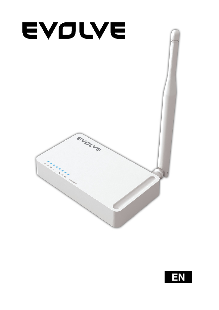
WR150N
Wireless router with built in
4-ports switch
User guide
Page 2

1. ACKNOWLEDGEMENTS
Thank you very much for purchasing this WR150N Wireless Router. This guide will introduce the
features of this device and tell you how to connect, use and configure the Router to connect with
Internet. Please follow the instructions in this guide to avoid affecting the Router’s performance by
improper operation.
2. PRODUCT OVERVIEW
2.1 Introduction
WR150N is a combined wired/wireless network connection device that integrates with internetsharing router and 4-port switch. It allows users to access Internet by DHCP/PPPoE/Static IP and can
expand the wireless coverage. WR150N can be also used as a repeater and a Wireless AP.
Generally, it is a high performance and cost-effective solution for home and small offices.
2.2 Features
- Complies with IEEE 802.11n and IEEE 802.11g/b standards for 2.4GHz Wireless LAN
- Up to 150Mbps wireless speed
- Supports PPPoE, Dynamic IP and static IP broadband functions
- Supports 64/128-bit WEP and TKIP/AES encryption
- IP/MAC/URL filtering makes access and time control more flexibly
- WDS mode makes it simple for WLAN expansion
- Supports WMM for improved audio and video streaming
- Multi-SSID allows you to create multiple SSIDs for different purpose
- Connects to secure network easily and fast using WPS
- Repeater function allows more PCs to surf Internet
- Supports port bandwidth control
- Easy to install and configure
2.3 Panel Layout
2.3.1 Front Panel
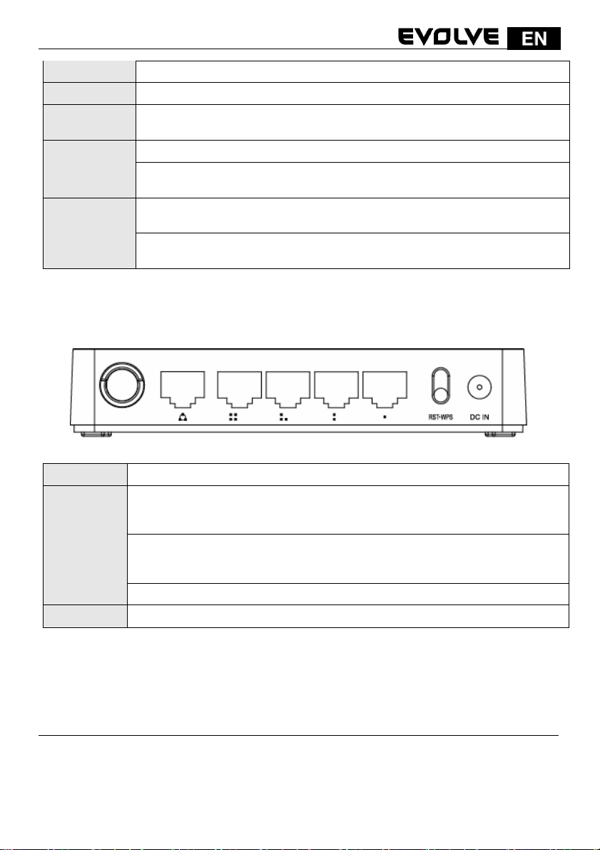
The front panel of Router WR150N consists of 8 LEDs, which is designed to indicate
connection status.
130
Page 3
W
A
WAN
of
f
POWER This indicator lights blue when the hub is receives power, otherwise it is off.
CPU This indicator blinks blue when Router powered on.
WLAN
This indicator
transmitting data to WLAN Router.
When the
WAN
During transmitting or receiving data through the
blinks blue.
When one
1/2/3/4 LAN
indicator lights blue.
During transmitting or receiving data through the LAN port the indicator
blinks blue.
2.3.2 Rear Panel
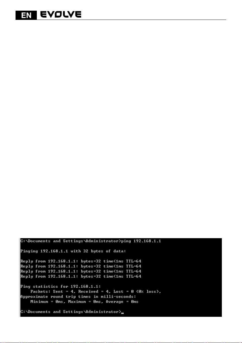
The figure below shows the rear panel of the router.
lights blue when there are wireless devices connected and
N port is connected successfully the indicator lights blue.
port the indicator
the LAN ports has a successful connection, the corresponding
DC IN The Power socket is where you will connect the power adapter.
RST: With the router powered on, press and
hold the button until the CPU
becomes quick-flash from slow-flash. And then release the button and wait the
RST/WPS
router to reboot to its factory default settings.
WPS: I
you have client devices you can press this button to quickly establish a
router and client devices and automatically configure wireless security for your
wireless network.
WAN This port is where you will connect the DSL/cable Modem, or Ethernet.
1/2/3/4 LAN This port connects the router to local PC.
Note: Press and hold RST/WPS button for about less than 5 seconds and the CPU LED indicator
changes its lighting, it is WPS working. If more than 5 seconds and the CPU LED not response, the
router will reboot to default factory settings.
3. HARDWARE INSTALLATION
3.1 Hardware Installation
For those computers you wish to connect with Internet by this router, each of the computers must
be properly connected with the router through provided UTP LAN Cables:
- 1. Connect the provided UTP LAN cable to one of the router’s LAN port.
131
LED
Page 4
- 2. Connect the other end of the UTP LAN cable to your computer’s LAN port.
- 3. Connect the second UTP LAN cable to router’s WAN port.
- 4. Connect the other end of the UTP LAN cable to ADSL or Modem port.
- 5. Plug the Power Adapter into the Router and then into an outlet.
- 6. Turn on your computer.
- 7. Check and confirm that the Power LED and LAN LED on the router are ON.
3.2 Check the Installation
The control LEDs of the WLAN Router are clearly visible and the status of the network link can be
seen instantly:
- 1. With the power source on, once the device is connected to the broadband modem, the Power,
CPU, LAN, WLAN and WAN port LEDs of the WLAN Router will blinks for one second indicating a
normal status.
- 2. When the WAN Port is connected to the ADSL/Cable modem, the WAN LED will light up.
- 3. When the LAN Port is connected to the computer system, the LAN LED will light up.
3.3 Set up the Computer
The default IP address of the Router is 192.168.1.1, the default Subnet Mask is 255.255.255.0.
Both of these parameters can be changed as you want. In this guide, we will use the default
values for description.
Connect the local PC to the LAN port on the Router. There are then two ways to configure the IP
address for your PC.
-1. Configure the IP address manually
Configure the network parameters. The IP address is 192.168.1.xxx (“xxx” range from 2 to
254). The Subnet Mask is 255.255.255.0 and Gateway is 192.168.1.1 (Router’s default IP
address).
- 2. Obtain an IP address automatically
Set up the TCP/IP Protocol in Obtain an IP address automatically mode on your PC.
Now, you can run the Ping command in the command prompt to verify the network
connection between your PC and the Router. Open a command prompt, and type in ping
192.168.1.1, then press Enter.
132
Page 5
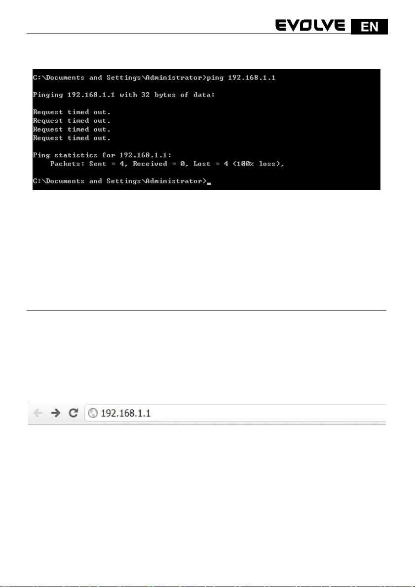
If the result displayed is similar to that shown in above figure, it means that the connection
between your PC and the Router has been established.
If the result displayed is similar to that shown in the above figure, it means that your PC has not
connected to the Router successfully. Please check it following below steps:
- 1. Is the connection between your PC and the Router correct?
If correct, the LAN port on the Router and LED on your PC’s adapter should be lit.
- 2. Is the TCP/IP configuration for your PC correct?
Since the Router’s IP address is 192.168.1.1, your PC’s IP address must be within
the range of 192.168.1.2 ~ 192.168.1.254, the Gateway must be 192.168.1.1.
4. CONNECTING TO INTERNET
This chapter introduces how to configure the basic functions of your router to access
Internet.
4.1 Accessing Web page
Connect to the Router by typing 192.168.1.1 in the address field of Web Browser. Then press
Enter key.
It will show up the following page that requires you to enter valid User Name and Password:
133
Page 6
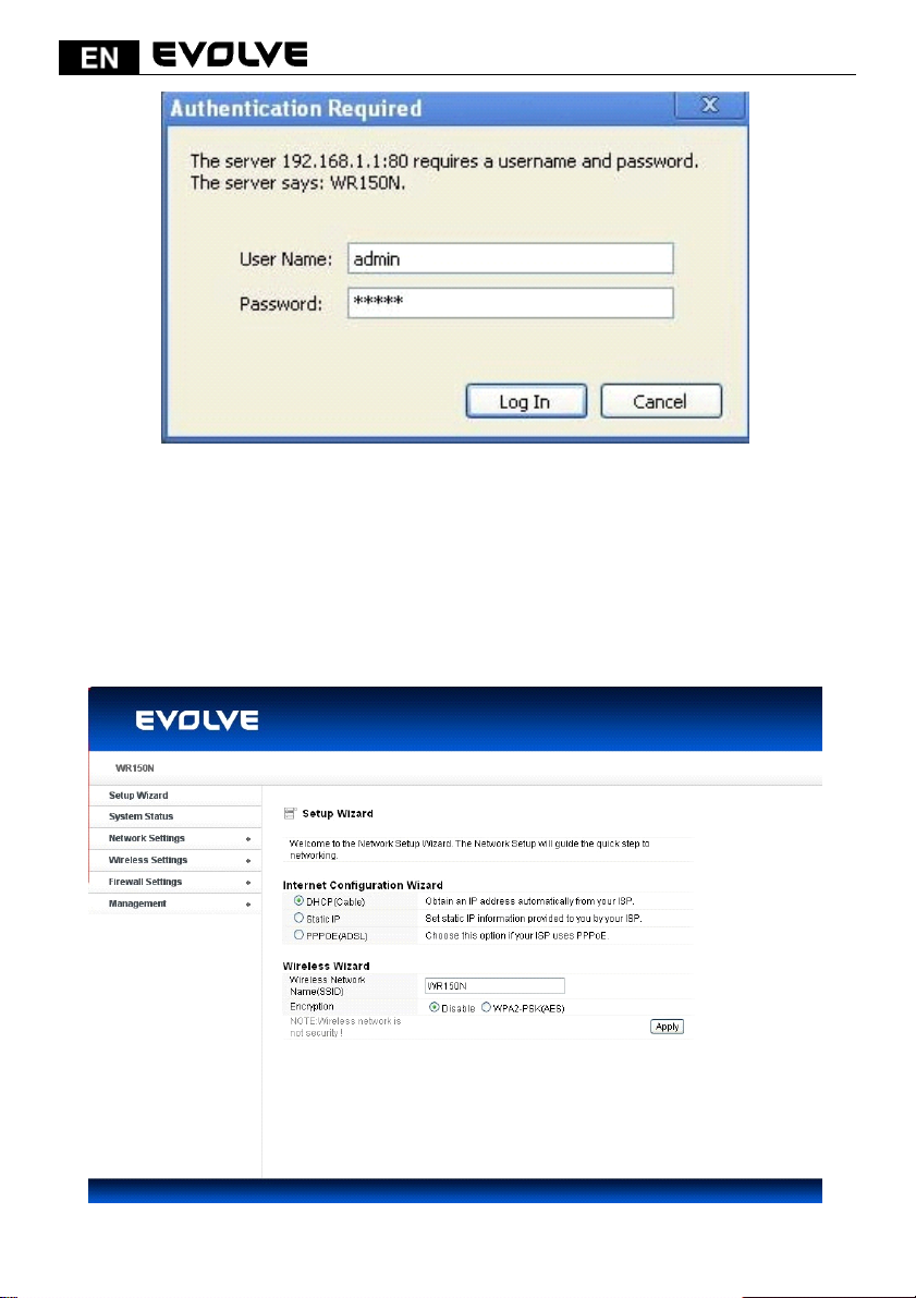
Enter admin for User Name and Password, both in lower case letters. Then click OK
button or press Enter key.
Note: If the above screen does not prompt, it means that your web-browser has been set to using
a proxy. Go to To o l s m e n u >Internet Options>Connections>LAN Settings, in the screen that
appears, cancel the Using Proxy checkbox, and click OK to finish it.
If the User Name and Password are correct, you can configure the router using the web browser.
Now you have logged into the web interface of the router.
134
Page 7
4.2 Changing Password
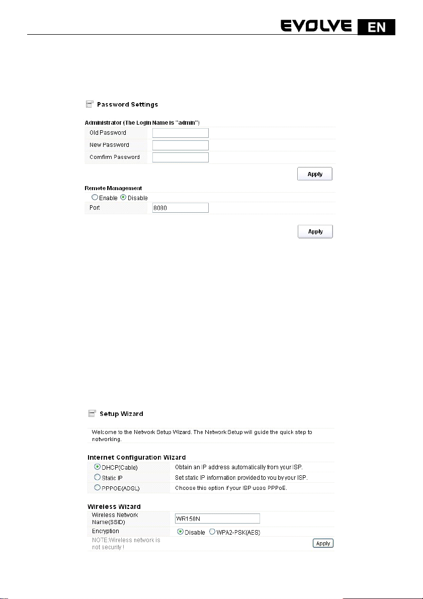
First, we recommend that you change the password to protect the security of your router. Please go
to Management-Password change the password required to log into your Router.
Old Password: please enter the current password of this router.
New Password: new password is used for administrator authentication.
Confirm Password: new password should be re-entered to verify its accuracy.
Note: password length is 8 characters maximum, characters after the 8
th
position will be
truncated.
The Remote Management part we will discuss later. Now just keep the setting not change and click
Apply.
4.3 Setup Wizard
After you login the web page of this router, the first page you can see is Setup Wizard. It is
provided as part of the web configuration utility. Users can simply finish the settings on this page to
get the Wireless Router ready to access Internet.
135
Page 8
4.3.1 Internet Configuration Wizard
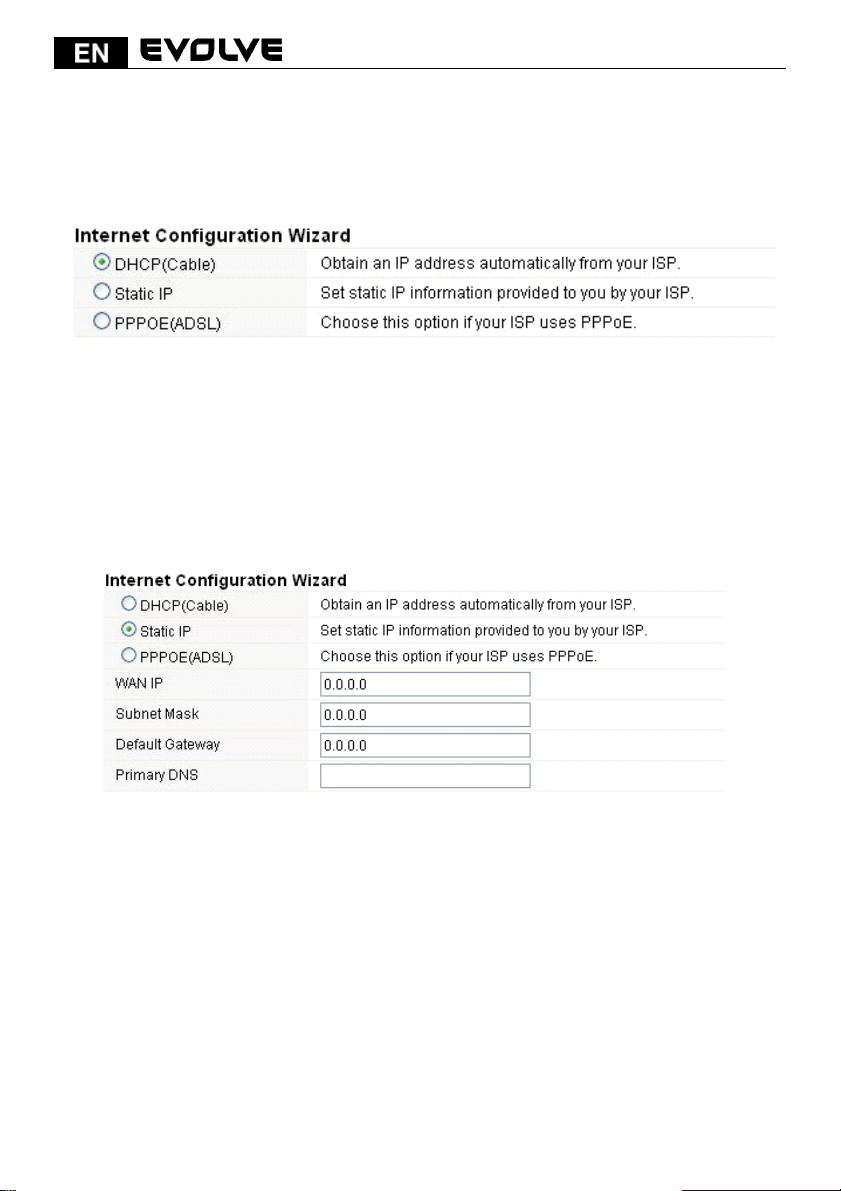
This interface is used to configure the parameters for Internet network which connects to the WAN
port of your Access Point. There are three methods provided to allow you to access Internet. Please
choose the appropriate one according to the information provided by your ISP (Internet Service
Provider).
4.3.1.1 DHCP (Cable)
If you choose DHCP (Cable), you will get a dynamic IP address from your ISP automatically and you
don't need to do any settings.
4.3.1.2 Static IP
If your ISP has provided the fixed IP that enable you to access Internet, please choose this option
and provide below information.
WAN IP Address: the IP address provided by your ISP.
Subnet Mask: This is used to define the device IP classification for the chosen IP address range.
255.255.255.0 is a typical net mask value for Class C networks. Generally it is provided by your ISP.
Default Gateway: This is the IP address of the host router that resides on the external network
and provides the point of connection to the next hop towards the Internet. This can be a DSL
modem, Cable modem, or a WISP gateway router. The router will direct all the packets to the
gateway if the destination host is not within the local network.
Primary DNS Address: The Domain Name System (DNS) is an Internet “phone book”, which
translates domain names to IP addresses. These fields identify the server IP addresses where the
DNS requested are forwarded by this router.
4.3.1.3 PPPoE (ADSL)
Point-to-Point Protocol over Ethernet (PPPoE) is a virtual private and secure connection between
136
Page 9

two systems that enables encapsulated data transport. It relies on two widely accepted standards:
PPP and Ethernet. It connects users through an Ethernet to the Internet with a common broadband
medium, such as wireless device or cable modem. All the users over the Ethernet can share a
common connection. If you use ADSL virtual dial-up to connect Internet, please choose this
option.
User Name: a specific valid ADSL user name provided by your ISP.
Password: the corresponding valid password provided by your ISP.
4.3.2 Wireless Wizard
This part is provided for wireless parameter settings. If setup correctly, you can access
Internet wirelessly.
Wireless Network Name (SSID): define a name for you wireless network.
Encryption: this step in fact is to set a password for your wireless network to prevent
others from using your WLAN.
Note: After you set the Encryption, please remember your Wireless Network Name (SSID). Then
search for the SSID on your PC to build a wireless connection with the device. So you can enjoy the
wireless function of this Router.
5. ADVANCED SETTINGS
This chapter allows users to configure advanced settings includes settings for Wireless, Network,
Firewall and Management. These settings are only for more technically advanced users who have
sufficient knowledge about wireless LAN. Also they should not be changed unless you know what
effect the changes will have on your wireless router.
5.1 System Status
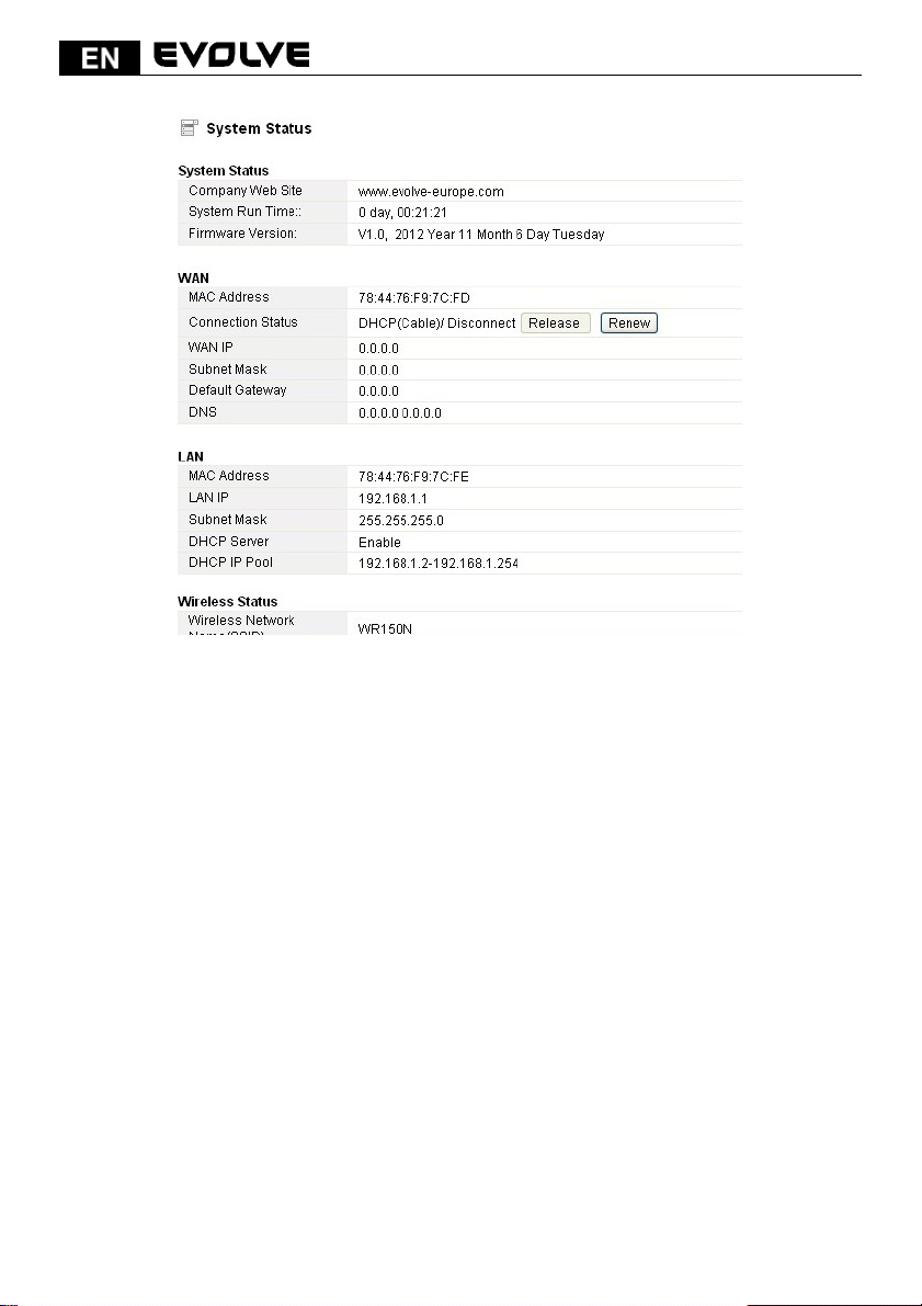
The System Status provides current status of this Router, including LAN and WAN interface
information, and Wireless settings. Also, you could get the current running firmware version or
firmware related information from this presentation.
137
Page 10
System Information
- Company Website: our company’s website.
- System Run Time: shows how long the system has run.
- Firmware Version: displays the current firmware version of the Router.
WAN
- MAC Address: displays the MAC address of the WAN interface.
- Connection Status: displays the connection type of the WAN port.
- WAN I P : shows the IP address of the WAN interface.
- Subnet Mask: displays the subnet mask of the WAN interface.
- Default Gateway: displays the assigned IP address of the default gateway.
- DNS: shows the DNS address.
LAN
- MAC Address: shows the MAC address of the LAN interface.
- LAN IP: displays the IP address of the LAN interface.
- Subnet Mask: shows the subnet mask address of the LAN interface.
- DHCP Server: displays the current status of DHCP server of the LAN interface.
- DHCP IP Pool: the IP address range that the DHCP server can assign to every PC connected
to this device.
Wireless
- Wireless Network Name(SSID): displays name of your WLAN.
- Wireless Mode: shows the IEEE standards it complies with.
- Channel: shows the frequency/Channel it works in.
- Broadcast SSID: shows you have enabled or disabled to broadcast your WLAN’s SSID.
The form on the bottom of this page displays the total packets your router has received or sent.
138
Page 11
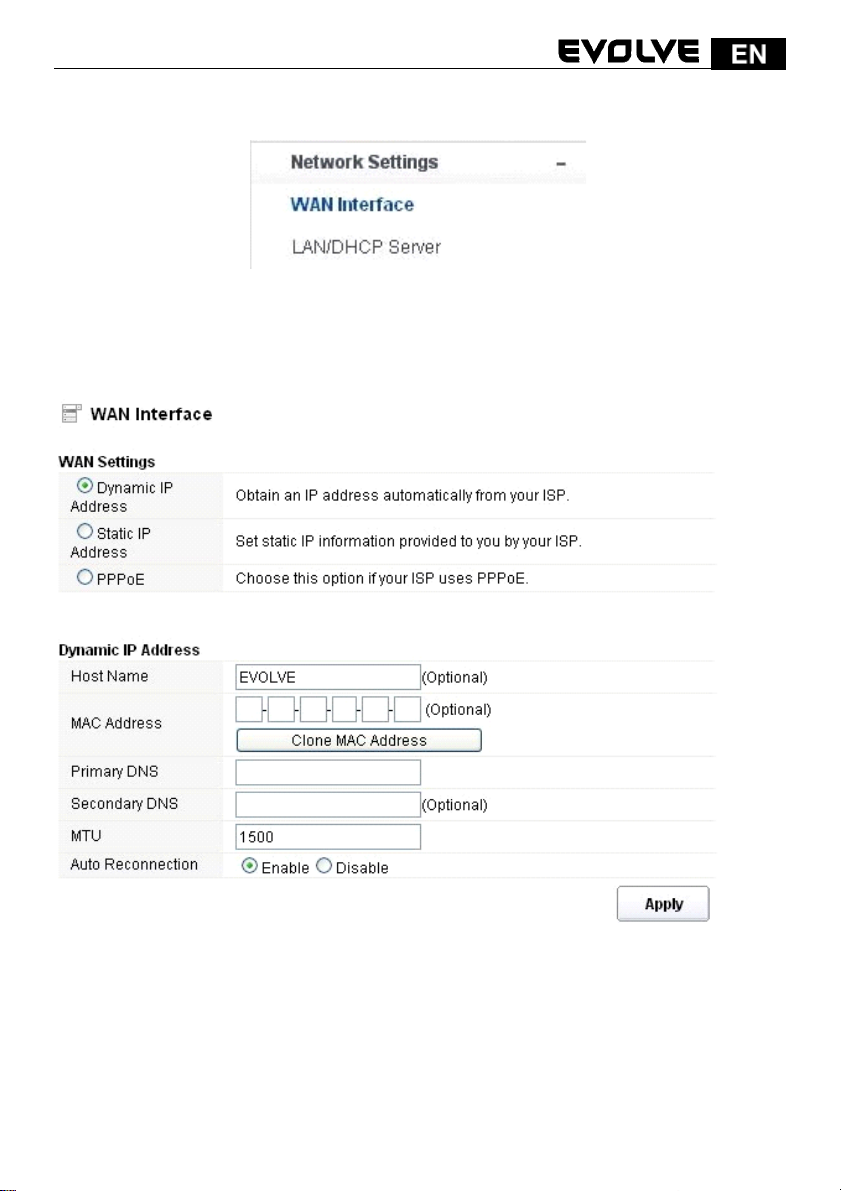
5.2 Network Settings
5.2.1 WAN Interface
This page is used to configure the parameters for the WAN port of your Access Point. Since we have
discussed this setting on Setup Wizard, here we introduce the MTU value.
MTU: It means Max Transmit Unit for packet. When using slow links, large packets can cause some
delays thereby increasing lag and latency. The default value is 1500.
Auto Reconnection: this function is enabled by default.
5.2.2 LAN/DHCP Server
Local Area Network (LAN) is a group of subnets regulated and ruled by router. The design of
network structure is related to what type of public IP addresses coming from your ISP. This page
139
Page 12
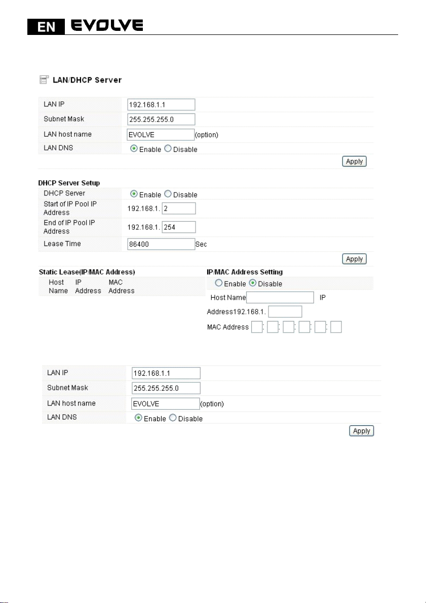
allows you to configure the parameters for LAN which connects to the LAN port of your Access
Point.
5.2.2.1 LAN
IP Address: This is the IP addresses to be represented by the LAN (including WLAN) interface that
is connected to the internal network. This IP will be used for the routing of the internal network
(it will be the Gateway IP for all the devices connected on the internal network).
Subnet Mask: This is used to define the device IP classification for the chosen IP address range.
255.255.255.0 is a typical netmask value for Class C networks which support IP address range from
192.0.0.x to 223.255.255.x. Class C network netmask uses 24 bits to identify the network and 8 bits
to identify the host.
LAN host name: this is optional, by default, it is EVOLVE.
LAN DNS: you can choose to enable or disable this function. By default, it is Enable selected.
5.2.2.2 DHCP Server Setup
Dynamic Host Configuration Protocol (DHCP) is a local area network protocol. If you enable this
140
Page 13
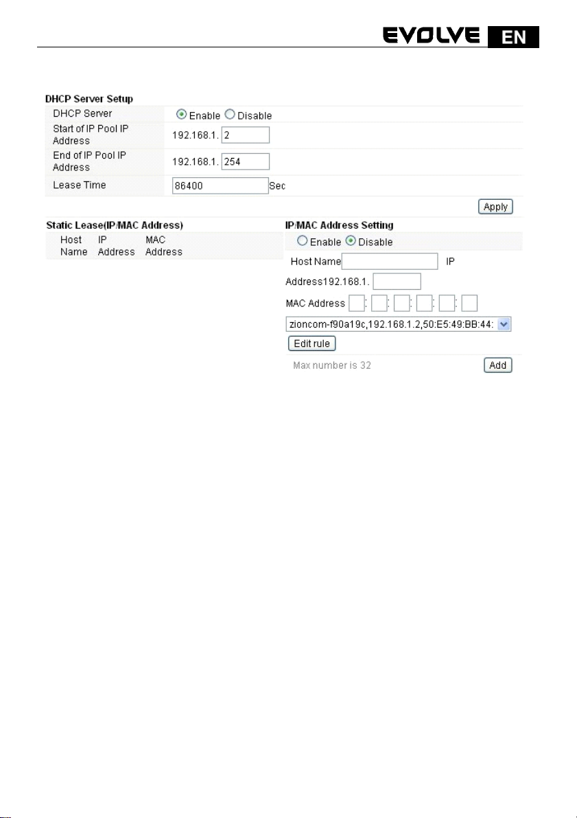
function, you will get a dynamic IP address from your ISP automatically. DHCP server means that all
the computers connected to this router will get IP address dynamically.
Start of IP Pool IP Address: displays the start IP Address of the range that will be assigned to each
computer connected with the router.
End of IP Pool IP Address: displays the ending IP Address of the range that will be assigned to
each computer connected with the router.
Lease Time: the IP addresses given out by the DHCP server will only be valid for the duration
specified by the lease time. Increasing the time ensure client operation without interrupt, but
could introduce potential conflicts. Lowering the lease time will avoid potential address conflicts,
but might cause more slight interruptions to the client while it will acquire new IP addresses from
the DHCP server. The time is expressed in seconds.
Static Lease (IP/MAC Address):
Static Lease function allows you reserve IP addresses, and assign the same IP address to the
network device with the specified MAC address any time it requests an IP address. This is almost the
same as when a device has a static IP address except that the device must still request an IP
address from the DHCP server. You can enable or disable this function.
Host Name: this represents the name of your IP address.
IP Address: displays the IP Address that you want to assign to network device.
MAC Address: the MAC Address of the computer that reserves the IP address.
141
Page 14
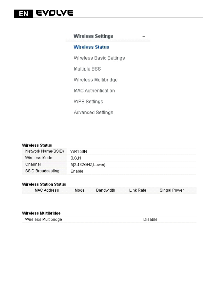
5.3 Wireless
5.3.1 Wireless Status
This page displays the current wireless status of the router.
5.3.2 Wireless Basic Settings
On this page, you could configure the parameters for Wireless LAN clients that may
connect to your Access Point.
142
Page 15
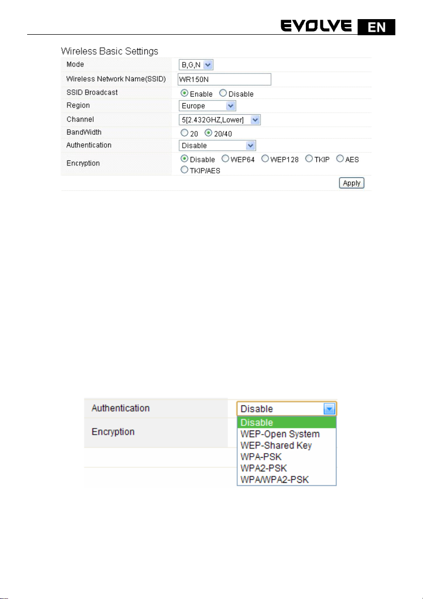
Mode: This option allows you to choose the radio standard for operation of your Router.
802.11b and 802.11g are old 2.4GHz mode, while 802.11n is the latest standard based on faster
Orthogonal Frequency Division Multiplexing (OFDM) modulation. Here, by default, the B, G, N Mode
is selected, this mode offers better compatibility.
Wireless Network Name (SSID): The name of the wireless network.
SSID Broadcast: you can choose to enable or disable to broadcast your SSID.
Region: this device supports 5 regions: USA, Canada, China, Japan and Europe. You can choose one
based on your position.
Channel: This option provides selectable channel numbers.
Bandwidth: This is the spectral width of the radio channel. Supported wireless channel spectrum
widths:
20MHz is the standard channel spectrum width.
40MHz is the channel spectrum with the width of 40MHz.
Authentication: you can choose one encryption method for your wireless LAN.
5.3.2.1 WEP
WEP (Wired Equivalent Privacy) is based on the IEEE 802.11 standard and uses the RC4 encryption
algorithm. Enabling WEP allows you to increase security by encryption data being transferred over
your wireless network. WEP is the oldest security algorithm, and there are few applications
that can decrypt the WEP key in less than 10 minutes.
143
Page 16
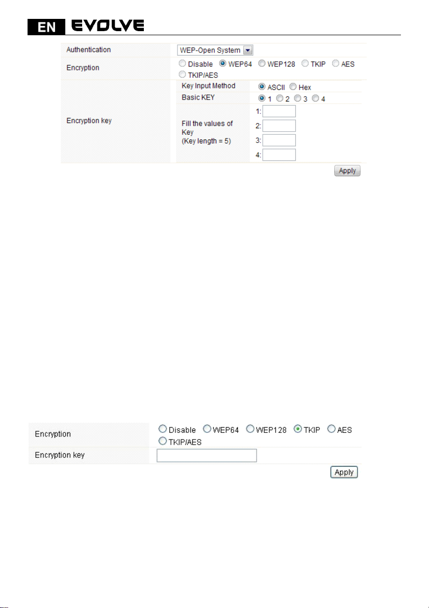
Authentication: One of the following authentication modes should be selected if WEP
security method is used:
Open System - station is authenticated automatically by AP.
Shared Key - station is authenticated after the challenge, generated by AP.
Encryption: 64-bit (selected by default) or 128-bit WEP Key length should be selected. The
128-bit option will provide a bit higher level of wireless security.
For 64-bit-specify WEP key as 10 Hex (0-9, A-F or a-f) characters (e.g. 00112233AA)
or 5 ASCII characters.
For 128-bit-specify WEP key as 26 Hex (0-9, A-F or a-f) characters (e.g.
00112233445566778899AABBCC) or 13 ASCII characters.
Encryption Key
Key Input Method: Hexadecimal (selected by default) or ASCII option specifies the character
format for the WEP key.
5.3.2.2 WPA/WPA2
Wi-Fi Protected Access (WPA) is the most dominating security mechanism in industry. It is separated
into two categories: WPA-personal or called WPA Pre-Share Key (WPA/PSK), and WPA-Enterprise or
called WPA/802.1x.
WPA2: it means Wi-Fi Protected Access 2, it is the current most secure method of wireless security
and required for 802.11n performance. This mode allows you to choose TKIP+AES Algorithm. If you
choose Enterprise related modes, you are required to enter RADIUS Server.
WPA Algorithms
TKIP--Temporal Key Integrity Protocol is one cipher for data encryption supported by
WPA.
AES--also know as CCMP, Counter Mode with Cipher Block Chaining Message Authentication Code
144
Page 17
Protocol, which uses the Advanced Encryption Standards (AES) algorithm.
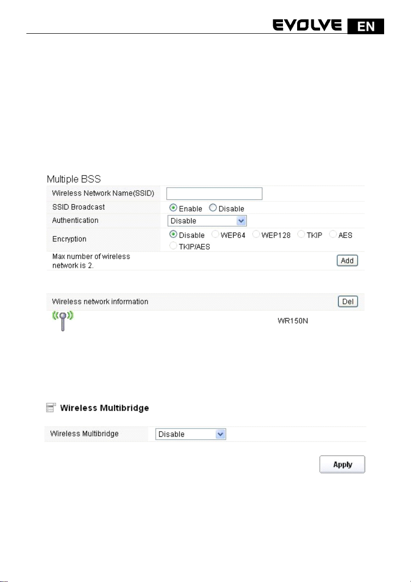
Encryption key: This is a pre-defined key used for encryption during data transmission. It has two
formats: Passphrase and Hex (64 characters). Then you need to enter the Pre-Shared Key,
either 8~63 ASCII characters, such as 012345678..(or 64 Hexadecimal
digits leading by 0x, such as “0x321253abcde…”).
Note: Since WEP has been proved vulnerable, you may consider using WPA2 for the most secure
connection. You should select the appropriate security mechanism according to your needs. No
matter which security suite you select, they all will enhance the over-the-air data protection
and/or privacy on your wireless network.
5.3.3 Multiple BSS
Wireless Network Name (SSID): define one more SSID for your WLAN. SSID Broadcast: choose to
enable or disable this function. Authentication: please choose one encryption method for this SSID.
Encryption: please refer to Wireless Basic Settings.
5.3.4 Wireless Multibridge
5.3.4.1 Repeater bridge/Repeater
These two Repeater methods can help you to expand the wireless coverage and allow more
terminals to access Internet.
145
Page 18
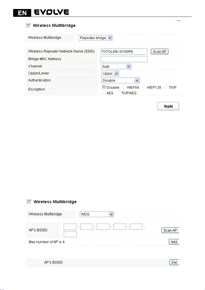
Wireless Repeater Network Name (SSID): choose the SSID you want to implement the repeater
function.
Bridge MAC Address: or you can enter the MAC address.
Channel: select one channel according to the main Router and your method.
Upper/Lower: you can keep it the default setting.
Authentication: select one encryption method for this repeater function.
Encryption: please refer to Wireless Basic Settings.
5.3.4.2 WDS
WDS means Wireless Distribution System. It is a protocol for connecting two access points
wirelessly. Usually, it can be used for the following application:
‹
Provide bridge traffic between two LANs though the air.
‹
Extend the coverage range of a WLAN.
To meet the above requirement, you must set these APs in the same channel and set MAC address of
other APs which you want to communicate with in the table and then enable the WDS.
146
Page 19
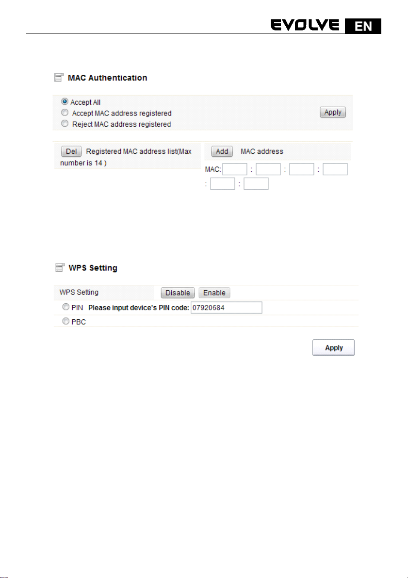
5.3.5 MAC Authentication
You can control the PC to connect with the wireless Router through MAC authentication
5.3.6 WPS Settings
WPS (Wi-Fi Protected Setup) provides easy procedure to make network connection between
wireless station and wireless access point with the encryption of WPA and WPA2. It is enabled by
default.
Pin Number: if you choose to configure WPS by PIN, then set the Pin number here.
PBC: you can choose this option as well.
147
Page 20
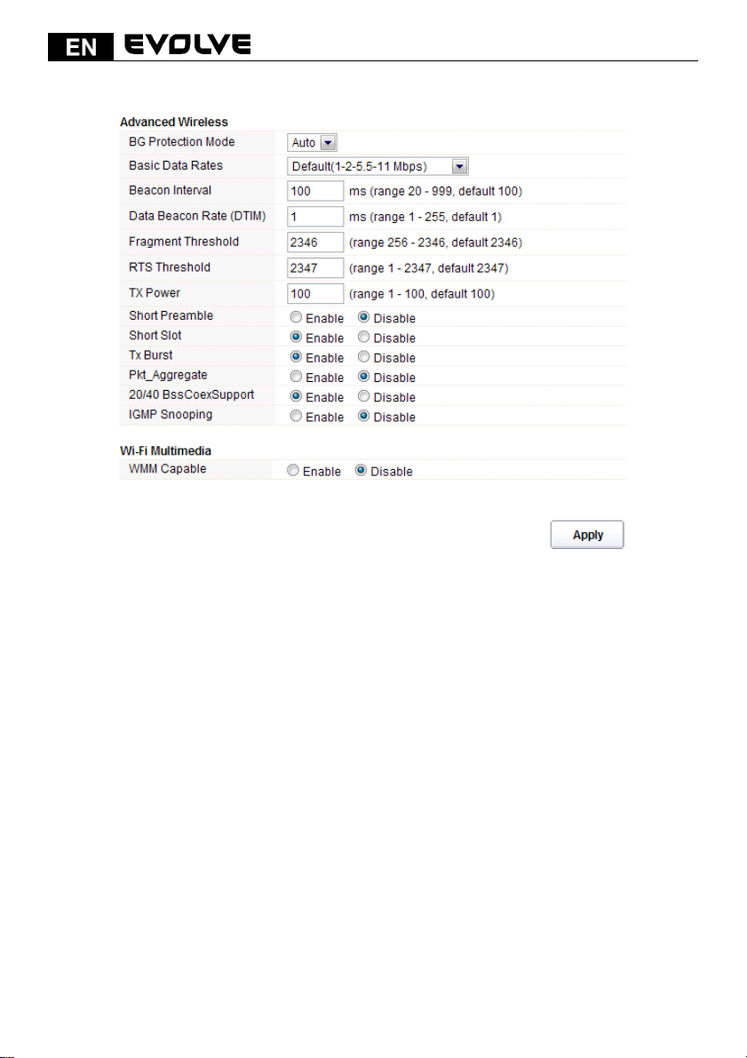
5.3.7 Advanced Settings
BG Protection Mode: Background Protection Mode, by default, it is Auto selected.
Basic Data Rates: you can choose the wireless data rate. This router provides three options. Be
default, it is Default (1-2-5.5-11Mbps).
Beacon Interval: By default, it is set to 100ms. Higher Beacon interval will improve the device’s
wireless performance and is also power-saving for client side. If this value set lower than 100ms, it
will speed up the wireless client connection.
Data Beacon Rate (DTIM): by default, its value is 1.
Fragment Threshold: specifies the maximum size for a packet before data is fragmented into
multiple packets. The range is 256-2346 bytes. Setting the Fragment Threshold too low may result in
poor network performance. The use of fragment can increase the reliability of frame transmissions.
Because of sending smaller frames, collisions are much less likely to occur. However, lower values
of the Fragment Threshold will result in lower throughput as well. Minor or no modifications of
the Fragmentation Threshold value is recommended while default setting of 2346 is optimum in
most of the wireless network use cases.
RTS Threshold: determines the packet size of a transmission and, through the use of an access
point, helps control traffic flow. The range is 0-2347 bytes. The default value is 2347, which means
that RTS is disabled.
RTS/CTS (Request to Send / Clear to send) are the mechanism used by the 802.11 wireless
networking protocols to reduce frame collisions introduced by the hidden terminal problem.
RTS/CTS packet size threshold is 0-2347 bytes. If the packet size the node wants to transmit is larger
148
Page 21
than the threshold, the RTS/CTS handshake gets triggered. If the packet size is equal to or less than
threshold the data frame gets sent immediately.
System uses Request to Send/Clear to send frames for the handshake that provide collision
reduction for an access point with hidden stations. The stations are sending a RTS frame first
while data is sent only after a handshake with an AP is completed. Stations respond with the
CTS frame to the RTS, which provide clear media for the requesting station to send the data.
CTS collision control management has a time interval defined during which all the other stations
hold off the transmission and wait until the requesting station will finish transmission.
TX Power: display the data transmission rate power.
Short Preamble: this option is to define the length of the sync field in an 802.11 packet. Most
modern wireless network uses shot preamble with 56 bit sync filed. By default, it is disabled.
Short Slot: by default, this is enabled.
Tx Burst: enable this function will make it easy for you to enhance the performance in data
transmission.
Pkt_Aggregate: by default, this is disabled.
20/40 BssCoexSupport: by default, it is enabled. Support 20/40 at the same time.
IGMP Snooping: if you enable this function, multicast traffic will be forwarded to ports that have
members of that group. Disabling IGMP snooping will make multicast traffic treated in the same
manner as broadcast traffic.
WMM Capable: by default, it is disabled.
WMM is an abbreviation of Wi-Fi Multimedia. It defines the priority levels for four access categories
derived from 802.1d (prioritization tabs). The categories are designed with specific types of traffic,
voice, video, best effort and low priority data.
5.4 Firewall
While the broadband users demand more bandwidth for multimedia, interactive applications, or
distance learning, security has been always the most concerned. The firewall of this router helps to
protect you local network against attack from unauthorized outsiders. It also restricts users in the
local network from accessing the Internet. Furthermore, it can filter out specific packets that
trigger the router to build an unwanted outgoing connection.
149
Page 22
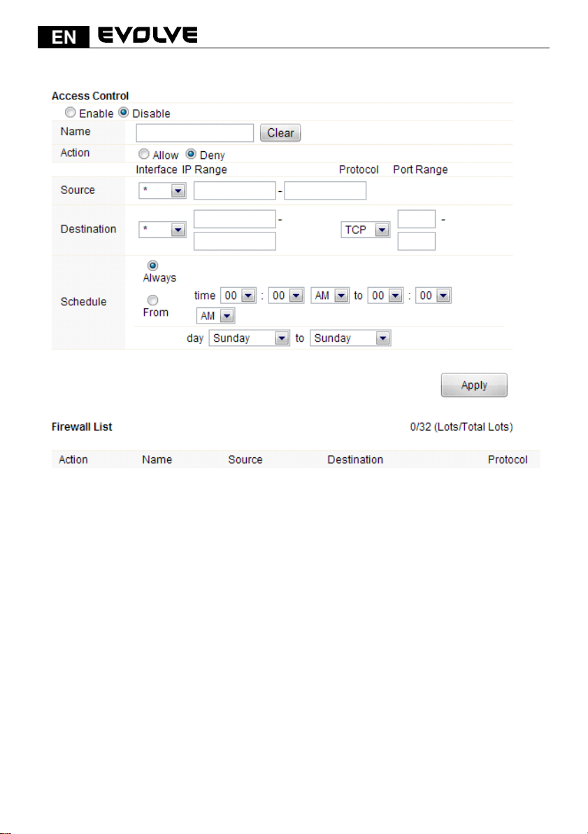
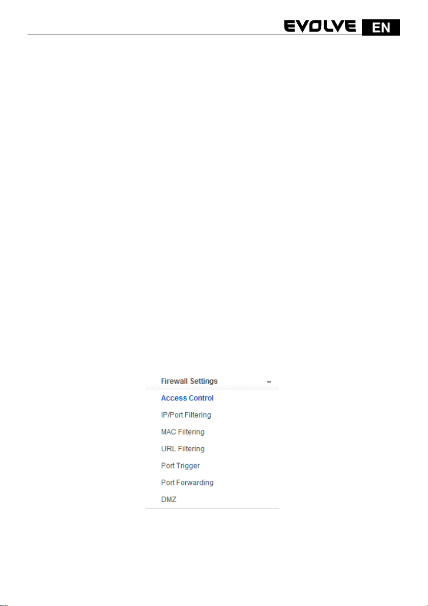
5.4.1 Access Control
First, you can choose to enable or disable this function according to your needs.
Name: Enter the name of the router.
Action: you could choose to allow or deny the following addresses entered by you.
Source: select the interface of the address, and enter the starting IP address that you want to deny
or allow.
Destination: select the interface of the address, and enter the ending IP address that you want to
deny or allow. About the Port Range, choose the protocol and enter IP range.
Schedule: this router has a built-in real time clock which can update itself manually or
automatically by means of Network Time Protocol (NTP). As a result, you can not only schedule the
router to dialup to the Internet at a specified time, but also restrict Internet access to certain
hours so that users can connect to the Internet only during certain hours, say, business hours. The
schedule is also applicable to other functions. You have to set your time before set schedule.
5.4.2 IP/Port Filtering
Depending on whether there is an existing Internet connection, or in other words “the WAN link
status is up or down”. You can restrict certain types of data packets from your local network to
Internet through the Gateway on this page.
150
Page 23
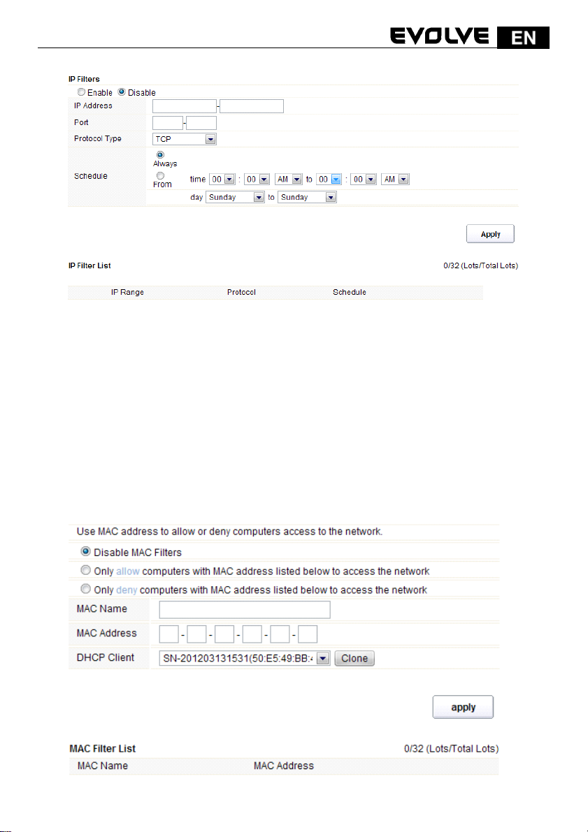
You can select to enable or disable IP/Port Filtering function. By default, it is disabled.
IP Address: the IP address range that you want to filter.
Port: the Port address that you want to filter.
Protocol Type: choose which particular protocol type should be filtered. Here you can
choose UDP/TCP.
Schedule: you can choose to always enable this filter function or create a schedule.
IP Filter List: this table will list the detailed information about the IP addresses that you want
to filter.
5.4.3 MAC Filtering
On this page, you can add some MAC addresses to be filtered to isolate users’ access from wired
LAN.
151
Page 24
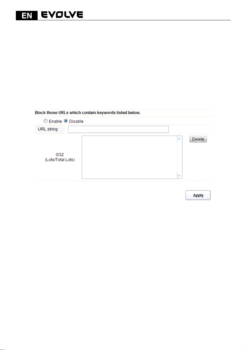
This router allows you to disable MAC Filtering function or allow/deny MAC address listed.
MAC Name: the name of the computer with the MAC you entered.
MAC Address: you can enter the MAC addresses that you want to deny or allow.
DHCP Client: display the information about one DHCP client.
MAC Filter List: this table will list the detailed information about the MAC addresses that will be
filtered.
5.4.4 URL Filtering
This page is used to deny LAN users from accessing the internet. Block those URLs which contain
keywords listed.
You can choose to enable or disable URL filtering function.
URL string: type in the string contained in URLs that you don’t allow LAN users to access. Enter the
URLs that you don’t allow LAN users to access. And you can also click Delete
the URLs you entered.
5.4.5 Port Trigger
This page allows you to trigger port for the traffic of special applications. Ensure that you keep
the application involved up-to-date to avoid falling victim to any security exploits.
152
button to delete
Page 25
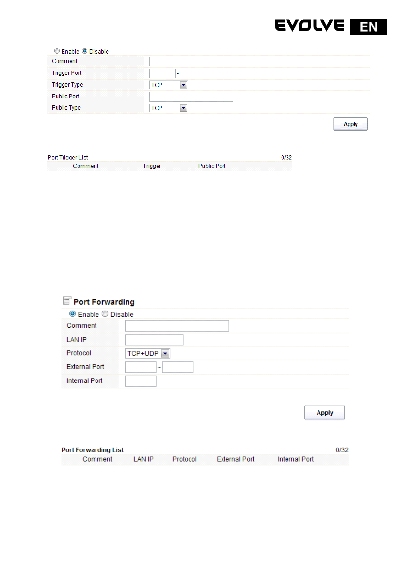
Enable/Disable: you can choose to enable or disable this function.
Comment: please enter the reason for this port trigger action.
Trigger Port: type in the starting & ending ports number of the service.
Trigger type: Specify the transport layer protocol. It could be TCP, UDP or both.
Public Port: type in the public port number.
Public Type: choose one transport layer protocol.
Port Trigger List: this table will list the detailed information about the ports that you set
before.
5.4.6 Port Forwarding
You could choose to enable or disable this function according to your requirement.
Comment: please enter the reason for this port forwarding action.
LAN IP: the IP of the host that is connected to the internal network and needs to be
accessible form external network.
153
Page 26
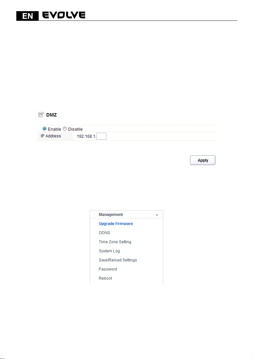
Protocol: the L3 protocol type of the IP Address.
External Port: range of the public port number.
Internal Port: internal port number. It is the TCP/UDP port of the application running on the host
that is connected to the internal network.
Port Forwarding List: the port forwarding list will show you the detailed information about the
forwarded port.
5.4.7 DMZ
DMZ means Demilitarized Zone. It can be enabled and used as a place where services can be placed
such as Web Servers, Proxy Servers and E-mail Servers such that these services can still serve the
local network and are at the same time isolated from it for additional security. DMZ is commonly
used with the NAT functionality as an alternative for the Port Forwarding while makes all the ports
of the host network device be visible form the external network side.
You can choose to enable or disable DMZ function.
IP Address: types in the IP address of the DMZ host
5.5 Management
5.5.1 Upgrade Firmware
This page allows you to upgrade the Access Point firmware to new version. Please note: DO NOT
power off the device during the upload because it may crash the system.
154
Page 27
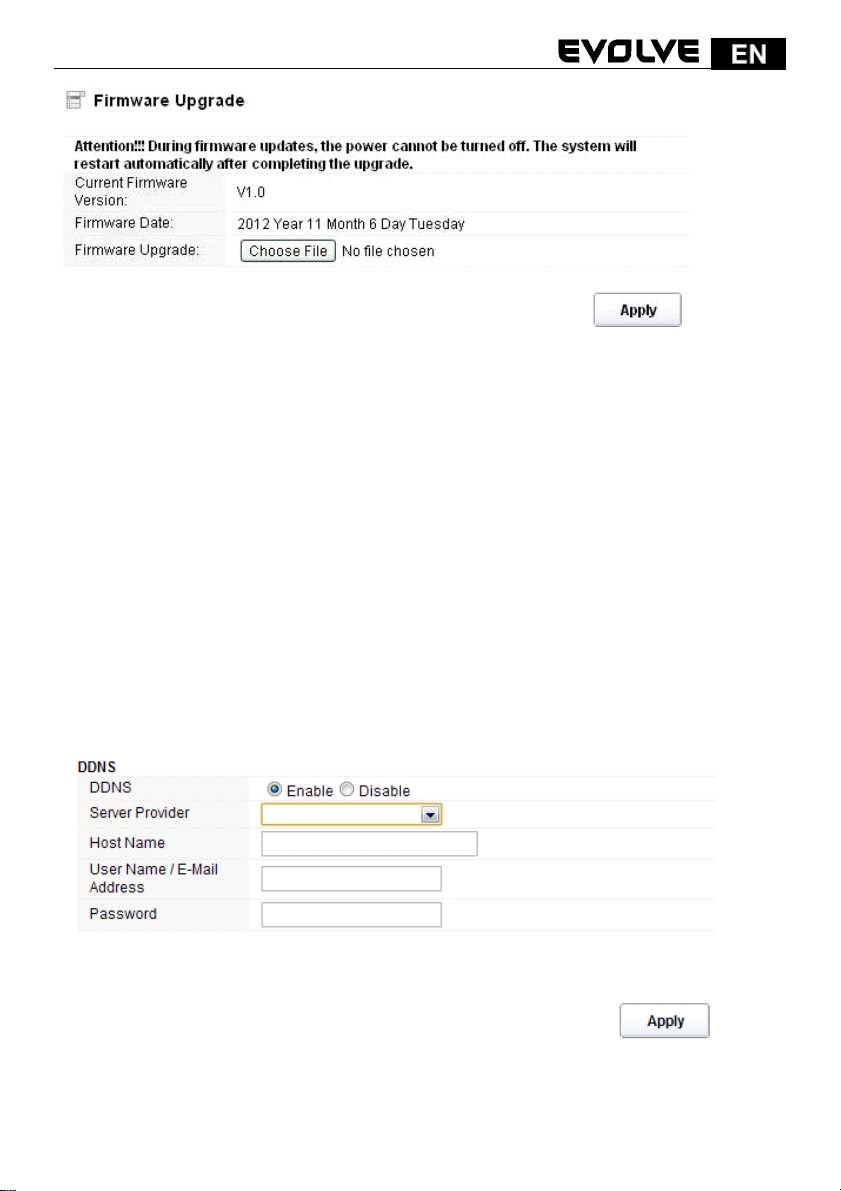
Current Firmware Version: shows the current firmware version.
Firmware Date: the date that you upgrade the current firmware.
Firmware Upgrade: select the firmware version on your computer then click Apply to
upgrade the firmware version.
5.5.2 DDNS
DDNS means Dynamic Domain Name System. The ISP often provides you with a dynamic IP address
when you connect to the Internet via your ISP. It means that the public IP address assigned to your
router changes each time you access the Internet. The Dynamic DNS feature lets you assign a
domain name to a dynamic WAN IP address. It allows the router to update its online WAN IP address
mappings on the specified Dynamic DNS server. Once the router is online, you will be able to use
the registered domain name to access the router or internal virtual servers from the Internet. It is
particularly helpful if you host a web server, FTP server, or other server behind the router.
Before you user the Dynamic DNS feature, you have to apply for free DDNS service to the DDNS
service providers. The router provides up to three accounts from three different DDNS service
providers. This router supports three service providers: DynDns, no-ip and
3322. Please log in the websites to register for free DDNS service.
You could choose to enable or disable DDNS function.
Service Provider: choose one service provider where you have applied for free DDNS
service.
155
Page 28
Host Name: type in the host name you registered from the DDNS provider.
User Name/Email Address: enter the User Name or Email you registered from the DDNS
provider.
Password: enter the Password or Key you set for the User Name.
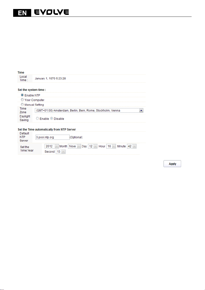
5.5.3 Time Zone Settings
This page allows you to maintain the system time by synchronizing with a public time server over the
Internet.
Local Time: it shows the current time by default.
Enable NTP: NTP means Network Time Protocol which is used to make the computer time
synchronized with its server or clock source, such as Quartz and GPS. It can provide highprecision time correction and prevent harmful protocol attack by confirming encryption. You need to
check this box to activate this page.
Time Zone: Select the Time Zone where the router is located.
Daylight Saving: If the Time Zone you choose implements daylight saving time, please select
this option. By default, it is disabled.
Default NTP Server: Please choose the corresponding NTP server to get right time. This is optional.
Set the Time: please set the right time according to your location.
5.5.4 System Log
This page can be used to set remote log server and show the system log.
156
Page 29
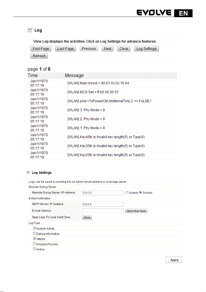
Click Log Settings button, it will display the page below:
Remote Syslog Server/IP Address: enter an IP address that allows syslog remote sending
function while System log messages are sent to a remote server.
157
Page 30
SMTP Server/IP: enter a SMTP Server address.
Email Address: enter an Email address.
Log Type: you can choose one type for log.
5.5.6 Save/Reload Settings
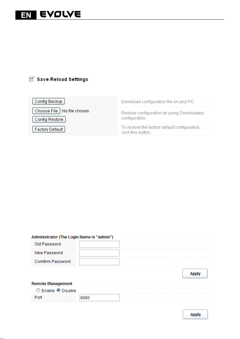
This page allows you to save current settings to a file or reload the settings from the file which was
saved previously. Besides, you can reset the current configuration to factory default.
Config Backup: click this button to save current settings to your local computer.
Choose File: if you want to reload the settings from the file saved before, you could click
Choose File button to choose the right file.
Config Restore: you will be asked whether to restore your configuration using saved file before.
Factory Default: click this button to restore the router settings to the default factory
settings.
5.5.7 Password
This page allows you to change the password to login web interface of this router. Also you can
enable or disable the Remote Management function here.
158
Page 31
Remote Management: if you enable this function, you can manage the router remotely.
Port: choose the Port number.
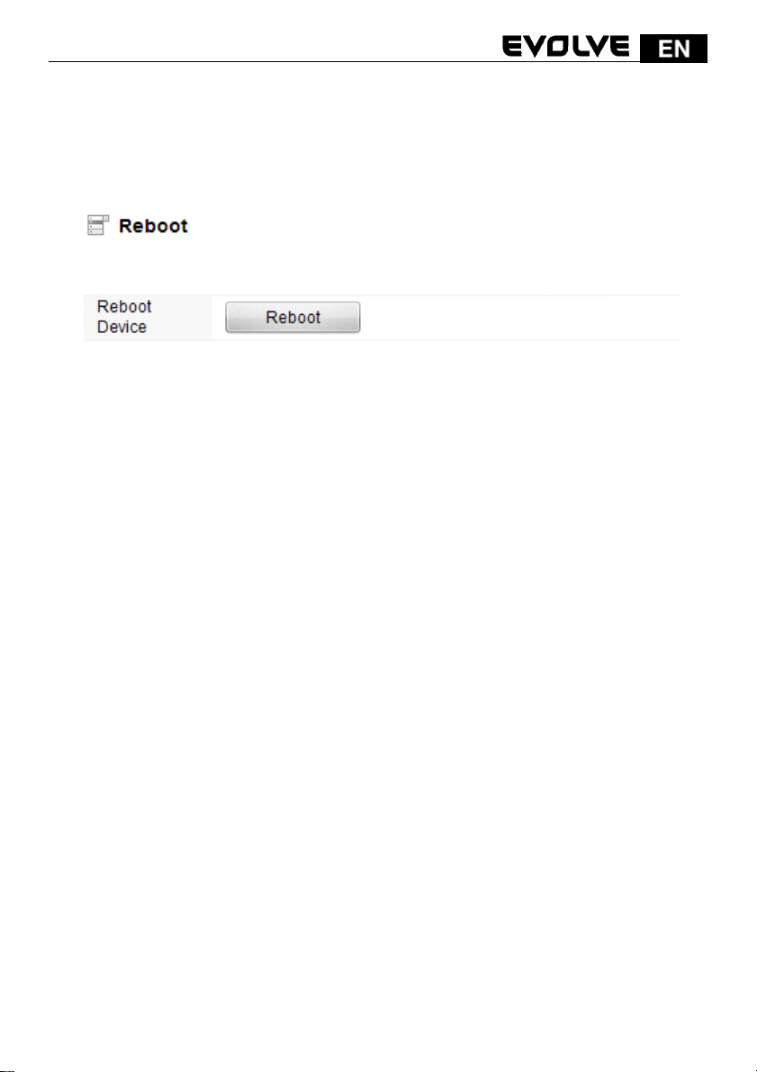
5.5.8 Reboot
Click this Reboot button to reboot your router quickly.
159
 Loading...