

Page 1

T-100-R Installation Guide
Page 2

Overview
Page 2Table of Contents
Installation
Wiring
T-100-R Z-Wave Thermostat 3-4
HVAC System Setup 6
Installer Settings Menu Items 7-9
Installer Settings Summary 10-11
Standard Gas/Elec HVAC System Wiring 13
Heat Pump HVAC System Wiring 14
Page 3
Model T-100-R Thermostat
Overview
This thermostat is compatible with most HVAC systems, including the following:
• 24VAC systems (requires both the 24R and 24C [common] wires)
• Standard gas/oil/electric heating systems
- 1 stage heating and cooling
- 2 stage heating and cooling
• Heat Pump systems:
- 1 stage heating and cooling
- 2 stage heating and cooling
- 2nd or 3rd stage Auxilary heating (heat strips)
• Do NOT use for line voltage controls (120/240VAC)
STOP! Before removing your existing thermostat, be sure to label the wires with the terminal markings on the old
thermostat and record them below.
Page 4
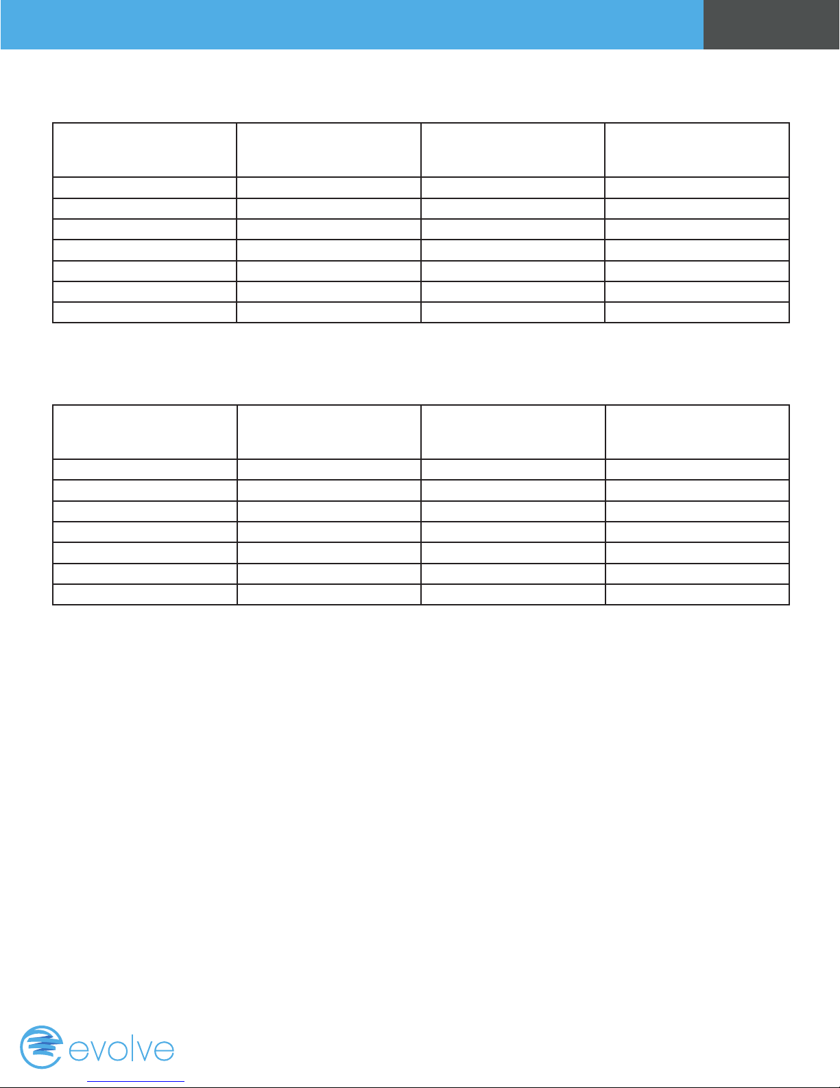
Standard HVAC System Wiring
Terminal Marking Meaning Typical Wire Color
C 24VAC Common Blue
R 24VAC Return Red
G Fan Green
W or W1 Heat stage 1 White
Y or Y1 Cool stage 1 Yellow
W2 Heat stage 2 Orange
Y2 Cool stage 2 Black
Heat Pump HVAC System Wiring
Terminal Marking Meaning Typical Wire Color
C 24VAC Common Blue
R 24VAC Return Red
G Fan Green
W or W1 Aux Heat White
Y or Y1 Compressor stage 1 Yellow
O (or B*) Change Over Valve Orange (brown*)
Y2 Compressor stage 2 Black
Page 4Overview
Record the old thermostat wire
connections and
terminal marking here
Record the old thermostat wire
connections and
terminal marking here
If you have a terminal marked “B” with a brown wire attached to it, that means you have a changeover (C/O) with heating
type heat pump system. Be sure to set the change over type in the Installer Settings menu to C/O Type: w/ Heat.
Otherwise, leave it set to w/ Cool.
Page 5
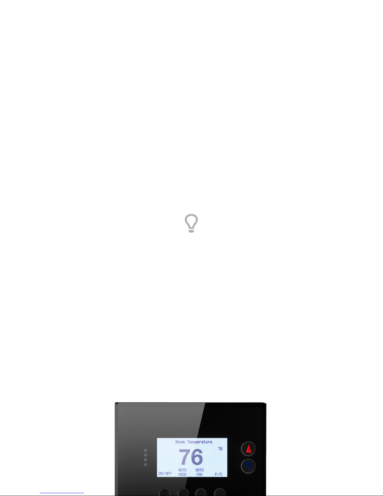
installation
Page 6
Page 6Installation
HVAC System Setup
Overview
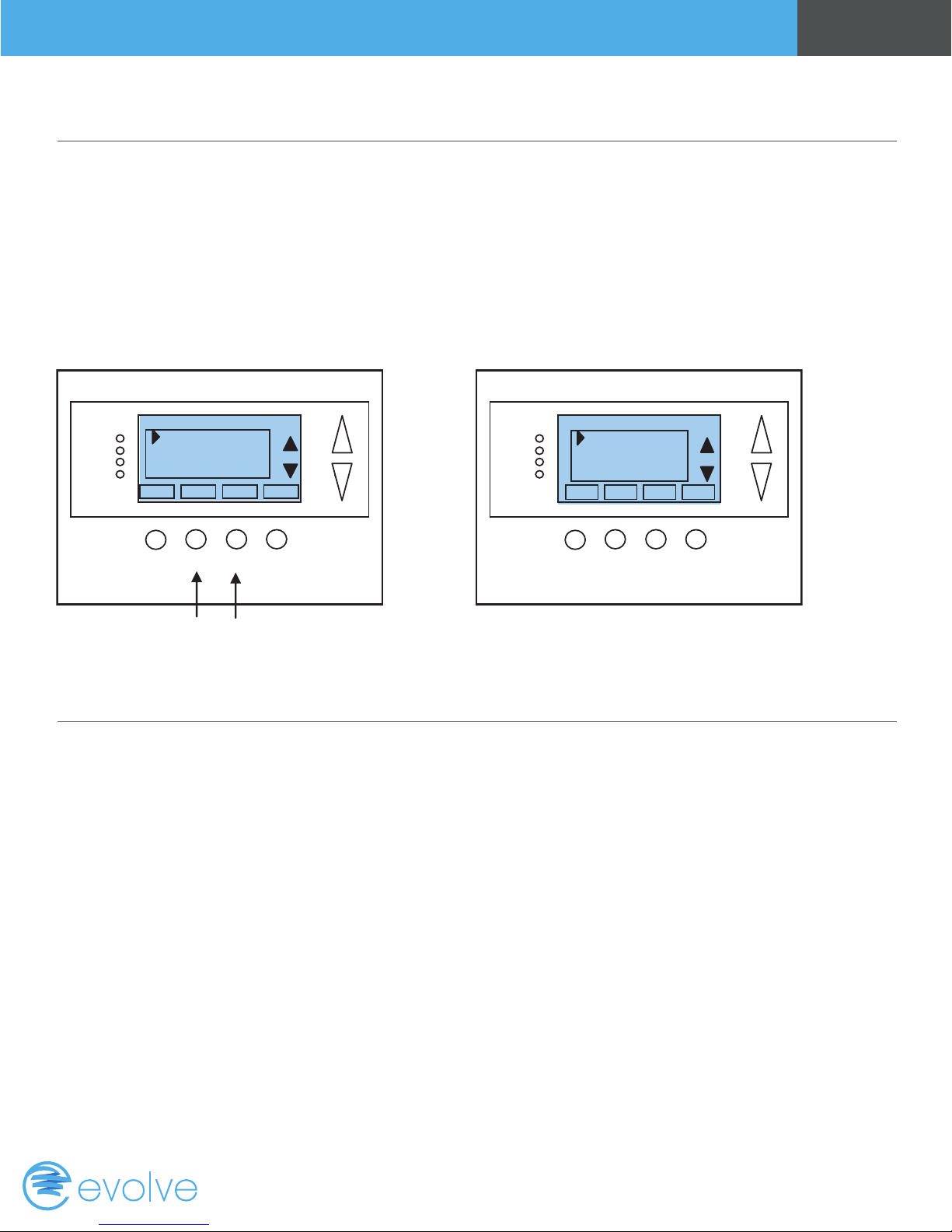
The thermostat requires that you setup the type and conguration of your HVAC system for proper operation. This is
done in the Thermostat Info screen Setup button or the Installer Settings screen on the thermostat. The Installer
Settings is a hidden screen. To access it, press the main menu button and when the main menu screen appears, press
and hold the middle two buttons for 5 seconds.
Thermostat Main Menu
Menu Selection
User Settings
Away Setpoints
ZWave Install
Thermostat Info
Done Select
Press and hold two middle buttons to enter
Installer Settings Screen
Installer Settings
Display Lock N
Service Mode
System Settings
Max Heat SP 90
Done Select
_
+
the Installer Settings screen
Installer Settings
Before operating the system, you must congure the thermostat for the correct HVAC system type. You will need to
know the following information to correctly congure the thermostat. The HVAC setup is in the Mechanical Settings
menu screen.
HVAC system type: What type HVAC system do you have? Standard or Heat pump
For Standard systems: Fan Type: Do you have Gas heat or Electric heat?
For Heat Pump systems: Change over valve (or reversing valve) type: Does your system change over with cooling
operation or with heating operation? Check your existing thermostat connects to help determine this. If the original
system had an orange wire connected to an “O” terminal, then you have a “changeover with cool” system. If you have a
brown wire connected to the “B” terminal, then you have a “change over with heat” system.
Page 7
Installer Settings Menu Items
Page 7Installation
Display Lock
Y = Display LOCKED
N = Display UNLOCKED
Allows you to lock or unlock the thermostat buttons. When the buttons are locked, you can still access the main
menu, but you will not be allowed to select any menu options. The Installer Settings hidden button operation is always
operational, allowing you to return to this screen and turn Display Lock off.
Service Mode
Test Mode
Y = Test mode on. Reduces all delays to 10 seconds for quicker system testing.
N = Test mode off. Normal system delays.
CAUTION: in test mode all system safety delays are shorten. Do not operate the system compressor in test mode.
Disconnect Y1 or Y2 outputs if using test mode on a live system.
Range: Y or N Default: N
Range: Y or N Default: N
System Settings
Submenu
Sets the HVAC operational settings below.
Mechanical Settings
Submenu
Sets the HVAC system type and conguration.
Type
Range: Gas/Elec or Heat pump
Default: Gas/Elec
Selects HVAC type, Gas/Electric or Heat pump
C/O Type
Range: w/Cool or w/Heat
Default: w/Cool
Selects the Heat Pump Changover Valve type
Fan Type
Range: Gas or Elec
Default: Gas
Selects the Fan type if system is Gas or Electric
2nd Stage Heat
Range: Y or N
Default: N
Enables the 2nd Stage Heat operation
Page 8

Page 8Installation
Aux Heat (HP)
Range: Y or N
Default: Y
Enables the Auxiliary Heat operation. Typically the
Aux Heat will be heat-strips in a Heat Pump system
2nd Stage Cool
Range: Y or N
Default: N
Enables the 2nd Stage Cool operation
Recovery Enable
Schedule Enable
Range: Y or N
Default: N
When enabled, the local thermostats scheduler
function is enabled
Range: Y or N
Default: N
For Heat Pump Systems - Intelligent setback
recovery is an automatic advance start of heating
to allow the system to be at a setpoint by the
scheduled time, without the use of Aux heating
Delta Settings
The Delta T Setting is the delta, or difference between, the setpoint and current temp for determining when a heat or cool
call comes on. The “delta” is the number of degrees away from setpoint.
H/C Delta
Range: 3 - 15 degrees
Default: 3F (1C)
Sets the minimum separation between heating and
cooling setpoints. Attempts to lower the cooling
below the heating setpoint by this amount will
PUSH the heating setpoint down to maintain this
separation. Same for setting the heating setpoint
above the cooling setpoint, it will PUSH the cooling
setpoint up to maintain this separation.
Heating Delta Stage 1 ON
Range: 1 - 8 degrees
Default: 1
Sets the delta from setpoint that stage 1 heating
starts.
Heating Delta Stage 1 OFF
Range: 0 - 8 degrees
Default: 0
Sets the delta from setpoint that stage 1 heating
stops. Stage 1 turns off at setpoint + Delta Stage 1.
Heating Delta Stage 2 ON
Range: 1 - 8 degrees
Default: 2
Sets the delta from setpoint that stage 2 heating
starts.
Heating Delta Stage 3 ON
Range: 1 - 8 degrees
Default: 3
Sets the delta from setpoint that stage 3 heating
starts.
Heating Delta Stage 2 OFF
Range: 0 - 8 degrees
Default: 0
Sets the delta from setpoint that stage 2 heating
stops. Stage 2 turns off at setpoint + Delta Stage 2.
Heating Delta Stage 3 OFF
Range: 0 - 8 degrees
Default: 0
Sets the delta from setpoint that stage 3 heating
stops. Stage 3 turns off at setpoint + Delta Stage 3.
Page 9

Page 9Installation
Cooling Delta Stage 1 ON
Range: 1 - 8 degrees
Default: 1
Sets the delta from setpoint that stage 1 cooling
starts.
Cooling Delta Stage 2 ON
Range: 1 - 8 degrees
Default: 2
Sets the delta from setpoint that stage 2 cooling
starts.
Max Heat SP
Sets the maximum heating setpoint value. Will not ramp or accept setpoints higher that this maximum.
Min Cool SP
Sets the minimum cooling setpoint value. Will not ramp or accept setpoints lower than this minimum.
Range: 40F to 109F (4C-43C) Default: 90F (32C)
Range: 44F to 113F (6C-45C) Default: 60F (15C)
Cooling Delta Stage 1 OFF
Range: 0 - 8 degrees
Default: 0
Sets the delta from setpoint that stage 1 Cooling
stops. Stage 1 turns off at setpoint - Delta Stage 1
Cooling Delta Stage 2 OFF
Range: 0 - 8 degrees
Default: 0
Sets the delta from setpoint that stage 2 Cooling
stops. Stage 2 turns off at setpoint -Delta Stage 2.
Minimum Run Time (MRT)
Sets the minimum run time before a heating/cooling cycle can turn off. Sets heating/cooling cycle time. Prevents rapid
cycling.
Minimum Off Time (MOT)
Sets the minimum off time before another heating/cooling cycle can begin. Provides compressor short cycle protection.
Temp Response
Adjust the temperature sensor sensitivity. Sets how fast the sensor responds to change.
Range: 1 - 9 minutes Default: 3
Range: 5 - 9 minutes Default: 5
Range: 1 - 6 Default: 2
Fan Cycler
The fan cycler function cycles the HVAC system fan for an ON period followed by an Off period continuously. Used
to provide minimum air ventilation requirements. When the Fan ON time is set to a value greater than 0, an additional
“Cycler” FAN mode is present when pressing the FAN button.
Fan ON Time
Range: 0 - 120 minutes
Default: 0 (=OFF)
Fan OFF Time
Range: 10 - 120 minutes
Default: 10
Page 10
Page 10Installation
Restore Defaults
Range: Yes, No / Default: No
Restores all settings to factory defaults.
Press Yes to restore defaults.
Press No to exit and not restore defaults.
Relay Status
Display the status (on/off) of the thermostat output relays
Installer Settings Summary
Setting Range Default
Display Lock Y or N N Locks out front buttons
Service Mode Submenu
Test Mode Y or N N Reduces delays for testing
System Settings Submenu
Mechanical Settings Submenu
Sys Type Std or HP Std
Fan Type Gas or Elec Gas
C/O Type w/Heat or w/Cool w/Cool
2nd Stage Heat Y or N N
Aux Heat Y or N Y
2nd Stage Cool Y or N N
H/C Delta 3 – 15 deg 3
Heat Delta Stage 1 On 1 – 8 1
Heat Delta Stage 1 Off 0 – 8 0
Heat Delta Stage 2 On 1 – 8 2
Heat Delta Stage 2 Off 0 – 8 0
Heat Delta Stage 3 On 1 – 8 3
Heat Delta Stage 3 Off 0 – 8 0
Cool Delta Stage 1 On 1 – 8 1
Cool Delta Stage 1 Off 0 – 8 0
Cool Delta Stage 2 On 1 – 8 2
Cool Delta Stage 2 Off 0 – 8 0
Max Heat SP 40-109F (4-42C) 90F
Min Cool SP 44-113F (6-45C) 60F
Min Run Time 1-9 min 3
Min Off Time 1-9 min 5
Temp Response 1-6 2
Fan Cycler Submenu
Fan Cycler ON time 0 – 120 min 0 0 = Fan Cycler OFF
Fan Cycler Off Time 10 – 120 min 10
Restore Defaults Yes or No No Exit = no
Page 11
USER SETTINGS Range Default
Filter Service Submenu
Service Interval Disabled, 100-4000 hrs 300
Maint Service Submenu
Maint Interval Disabled, 100-4000 hrs 3000
Screen Timeout (to minimized screen) 0, 20-120 sec 0 0 = off , will not timeout
F/C Mode F or C F
Sensor Calibration Submenu Internal -7 to +7 0
Backlite/Display Submenu
Backlight Timeout 0, 20-120 0 0 = backlite off
Backlight On Brightness 0-100% 100%
Backlight Off Brightness 0-100% 0%
Contrast 0-20 14%
Page 11Installation
Page 12
wiring
Page 13
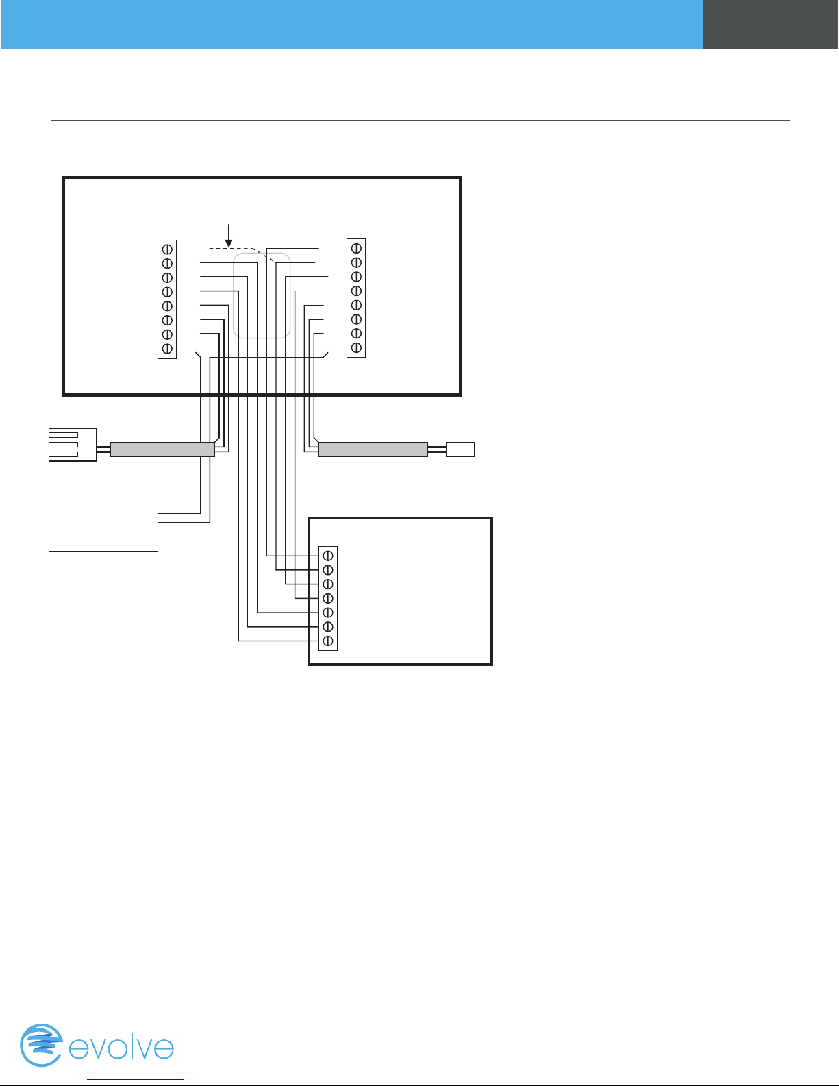
Standard Gas/Electric HVAC System Wiring
Thermostat Back
Page 13Wiring
Optional 24R Connection for single transformer HVAC Systems
RC and RH are jumpered together on thermostat board.
Cut RC/RH jumper JP1 for separate heating & cooling transformers
Cooling 24V
Fan
Cooling stage 1
Cooling stage 2
Remote Sensor 2
Remote Sensor 2
Sensor shield
Humidity Relay Com
24RC
G
Y1
Y2
RS2
RS2
RSC
HC
24C
24RH
W1
W2/O
RS1
RS1
RSC
Remote Outside Sensor
Contact
Closure
Input
Humidifier/Dehumidifier
Thermostat Connection
24VAC Com
24V Heating
Heating stage 1
Heating stage 2
Remote Sensor 1
Remote Sensor 1
Sensor shield
H1
Humidity Relay
Shielded cable Shielded cable
Remote Indoor Sensor
Standard HVAC System
C 24VAC Common
R 24VAC Return
W1 Heat Stage 1
W2 Heat Stage 2
G Fan
Y1 Compressor Stage 1
Y2 Compressor Stage 2
Default Setup:
• Gas/Elec
• Gas Heat
• 1 Stage Heating
• 1 Stage Cooling
No setup required for
this conguration.
Setup
To set the HVAC system type, go to the Thermostat Info screen and press Setup button.
• Type - Set the HVAC System Type: set to Gas/Elec
• Fan Type - Set the HVAC Fan Type: Set to Gas for typical gas furnance (fan is controlled by the furnance) or set to
Elec for electrical heat (fan call with heat)
• C/O type - Not used for standard systems. Ignore this setting.
• 2nd Stage Heat - Enable second stage heating outputs. If you have a single stage heating system, leave this set to
N. If you have a 2 stage heating system, set to Y to enable.
• Aux Heat (HP) - Not used for standard systems. Ignore this setting.
• 2nd Stage Cool - Enable second stage cooling outputs. If you have a single stage cooling system, leave this set to
N. If you have a two stage cooling system, set to Y to enable.
Page 14
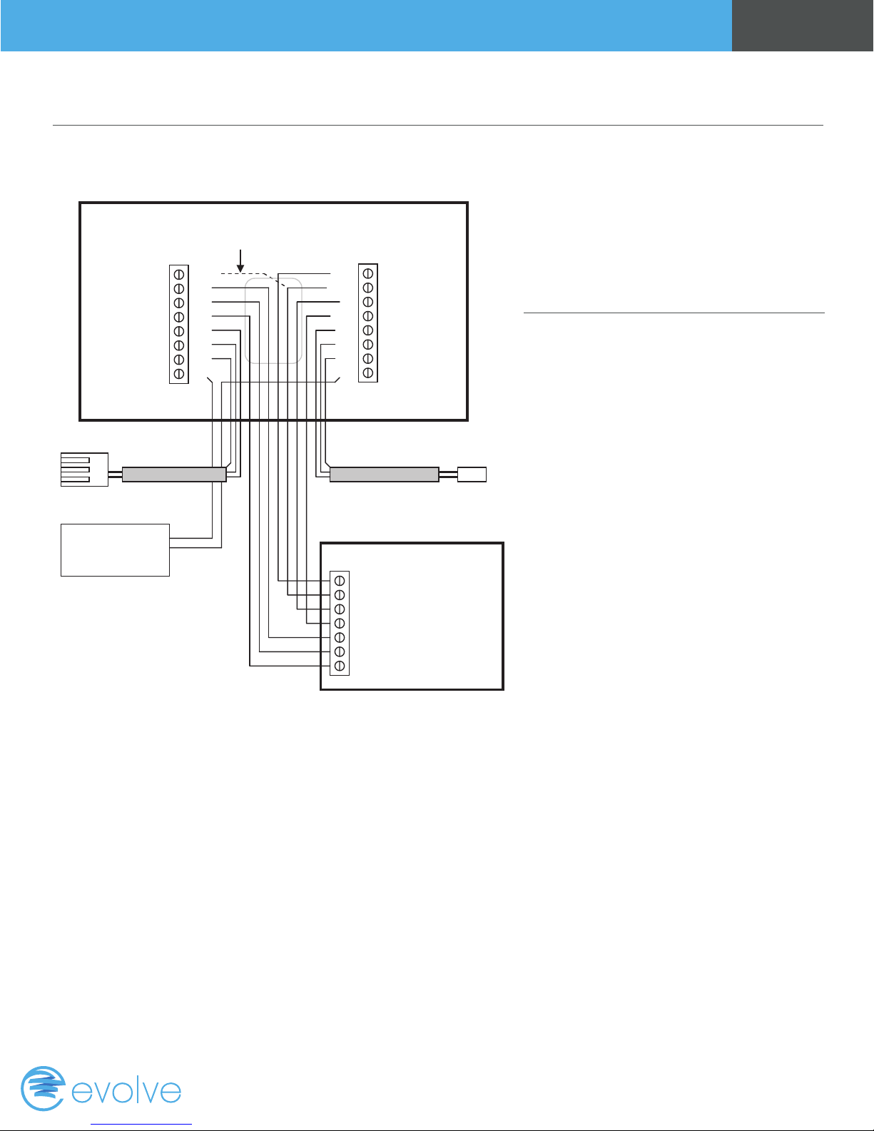
Heat Pump HVAC System Wiring
Thermostat Back
Page 14Wiring
Cooling 24V
Fan
Cooling stage 1
Cooling stage 2
Remote Sensor 2
Remote Sensor 2
Sensor shield
Humidity Relay Com
Remote Outside Sensor
Contact
Closure
Input
Humidifier/Dehumidifier
For Heat Pump systems, connect the 24R connection
to either the 24RC or 24RH
24RC
G
Y1
Y2
RS2
RS2
RSC
HC
24C
24RH
W1
W2/O
RS1
RS1
RSC
H1
Shielded cable Shielded cable
Heat Pump HVAC System
Thermostat Connection
C 24VAC Common
R 24VAC Return
W1 Aux Heat
O Change Over Valve
G Fan
Y1 Compressor Stage 1
Y2 Compressor Stage 2
24VAC Com
24V Heating
Aux Heating
Change Over Valve
Remote Sensor 1
Remote Sensor 1
Sensor shield
Humidity Relay
Remote Indoor Sensor
Note!
If you get heating when you
expected cooling, change the C/O
type to the opposite setting.
Setup
To set the HVAC system type, go to the
Thermostat Info screen and press Setup
button.
• Type - Set the HVAC System Type: set to
Heat Pump
• Fan Type - Automatically set for heat
pump systems. Ignore this setting.
• C/O type - Change Over (reversing) Valve
Type. Heat pumps change from heating to
cooling by reversing operation.You must
congure the thermostat’s changeover
valve setting to work correctly with your
HVAC system.
• Check your system information to be sure and note the color of original thermostat wire and the terminal it was
connected to. No matter what the old stat connection was (O or B), connect the wire to the thermostats W2/O
terminal. The setting of the C/O Type will set the correct system operation. For change over with cool systems
(Orange wire, O terminal): set C/O type to w/cool (most common and default setting). For change over with heat
systems (Brown wire, B terminal): set C/O type to w/heat.
• 2nd Stage Heat - Enable second stage heating outputs. If you have a single stage heating system, leave this set to
N. If you have a 2 stage heating system, set to Y to enable.
• Aux Heat (HP) - If you have auxiliary heat strips, set this to Y to enable.
• 2nd Stage Cool - Enable second stage cooling outputs. If you have a single stage cooling system, leave this set to
N. If you have a two stage cooling system, set to Y to enable.
Page 15
Page 16

www.evolvecontrols.com
 Loading...