

Page 1
INSTALLATION GUIDE
2018
power beam
Page 2
POWER BEAM INSTALLATION GUIDELINES
Table of Contents
List of Tools 02
Wiring Schematic 03
Power Beam 04
Electric 05
Extension Modules 07
Privacy Glass 08
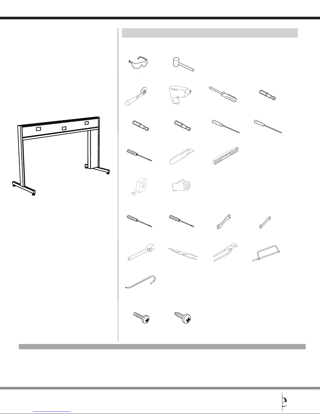
Required Tools
Required Tools
Safety Glasses
Fabric Spline Roller*
5/16” Nut-Driver
Large 1/4” Blade Screwdriver
Tape Measure
Rubber Mallet
Power Prill (var speed, rev)
3/8” Nut-Driver
Utility Knife
Gloves
Magnetic drill bit holders
#2 Robertson Screwdriver
48” Long Level
1/4” Nut-Driver
#3 Robertson Screwdriver
Additional items you may find useful:
#2 Phillips Screwdriver
Adjustable 8” Wrench
General Purpose Prybar
Screws Used During Installation
1/2” Pan Head Screw 1/2” Pan Head Tapping Screw
* These Items are available through customer care at 800-220-1900.
#3 Phillips Screwdriver
Needlenose Pliers
Please contact your Global CustomerCare Representative at 800-220-1900 for any questions or concerns.
1/2” Wrench
Large Channel Lock Pliers
9/16” Wrench
Fine tooth Saw (Hacksaw)
NOTE: Any alterations to listed components will void the manufacturer’s warranty.
The manufacturer will not be responsible for any damage or bodily harm caused by alterations in accordance with national or local electrical codes and manufacturer’s specifications.
In accordance with the manufacturer’s policy of continual product improvement, the product presented in this document is subject to change without notice or obligation.
Evolve Customer Support available at 856.552.4000, 888.827.2500, from 8:30 am - 5:30 pm Eastern time, or fax at 856.552.4001.
2 evolvefurnituregroup.com
Page 3
POWER BEAM INSTALLATION GUIDELINES
Wiring Schematic
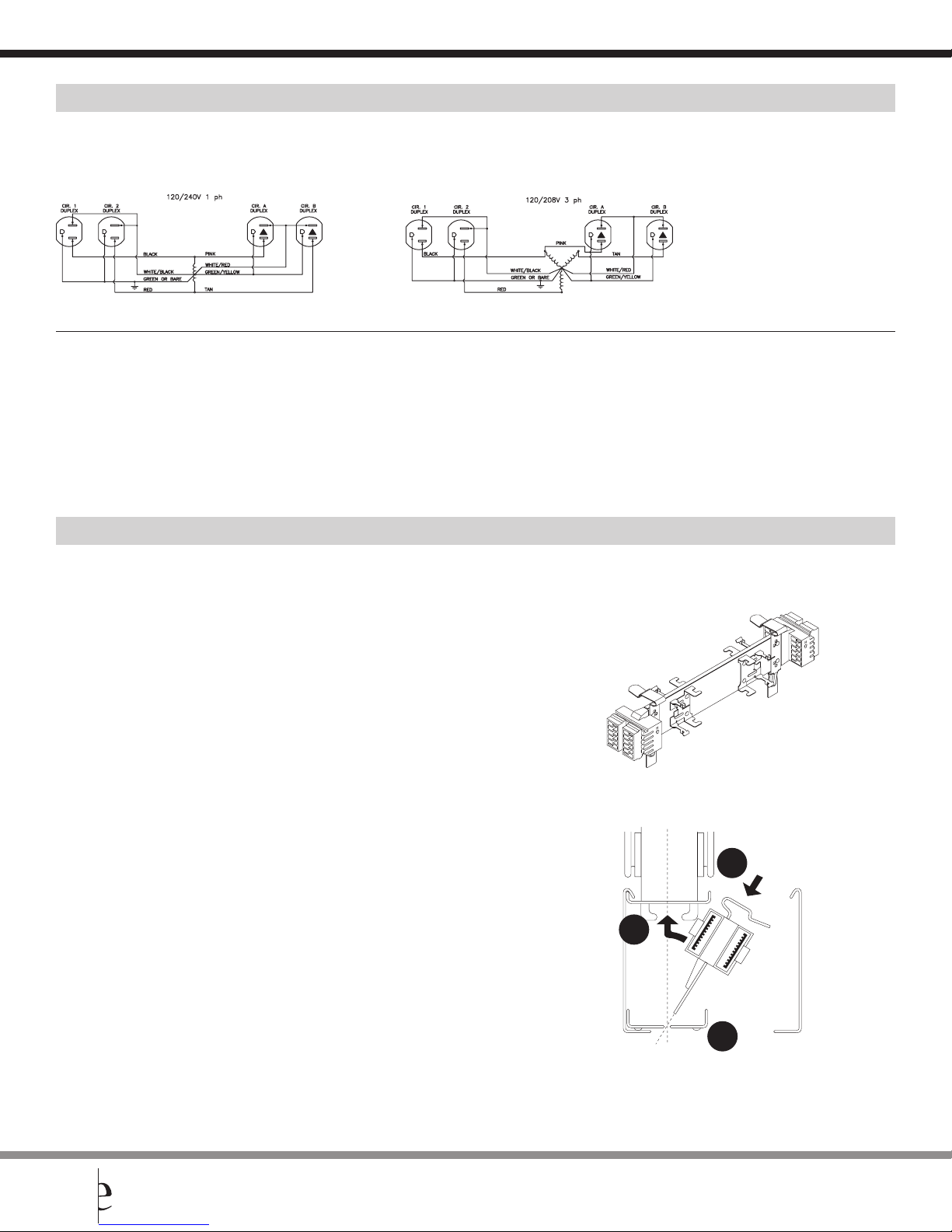
4-2-2 Wiring Schematic
8-Wire Shared Neutral
“2 + 2” - 2 Utility Circuits, 2 Dedicated
8 Wires 4 Circuits Receptacles Specifications
4 Lines (12 ga.) 2 Utility circuits Duplex - Up to 12 duplex receptacles per circuit System rated for connection to a grounded 120/240 V single phase, 20A,
2 Neutrals (10 ga.) 2 Dedicated Circuits (Up to 48 per infeed) 60Hz or 120/208 V, 3 phase, 20A, 60Hz branch circuit for U.S. and 15A if
2 Grounds (12 ga.) product is marked with a C-UL Mark. Outlets rated 15A max.
Power Distribution Housing
Parts List
1 Power Distribution Housing
A Power Distribution Housing is connected to the power beam raceway channel to
create a powered beam and usb. It serves to provide a point of attachment and electrical
connection for duplex receptacles, flexible harness connectors, and power entry
components.
Ensure that all panels are mechanically connected prior to electrical connection.
STEP 1: Raceway covers must be removed to allow installation.
STEP 2: Attach the Power Distribution Housing to the panel raceway channel. To
do this, slide the bottom fingers of the spring clips “A“ (attached at either end of
the Power Distribution Housing) into the slots in the bottom of the raceway channel
and snap the top of the spring clips “B” into the brackets provided at the top
of the raceway, “C” above the slots.
STEP 3: Replace the raceway cover.
B
C
evolvefurnituregroup.com 3
A
Evolve Customer Support available at 856.552.4000, 888.827.2500, from 8:30 am - 5:30 pm Eastern time, or fax at 856.552.4001.
Page 4
POWER BEAM INSTALLATION GUIDELINES
• Summer 2017
Power Beam
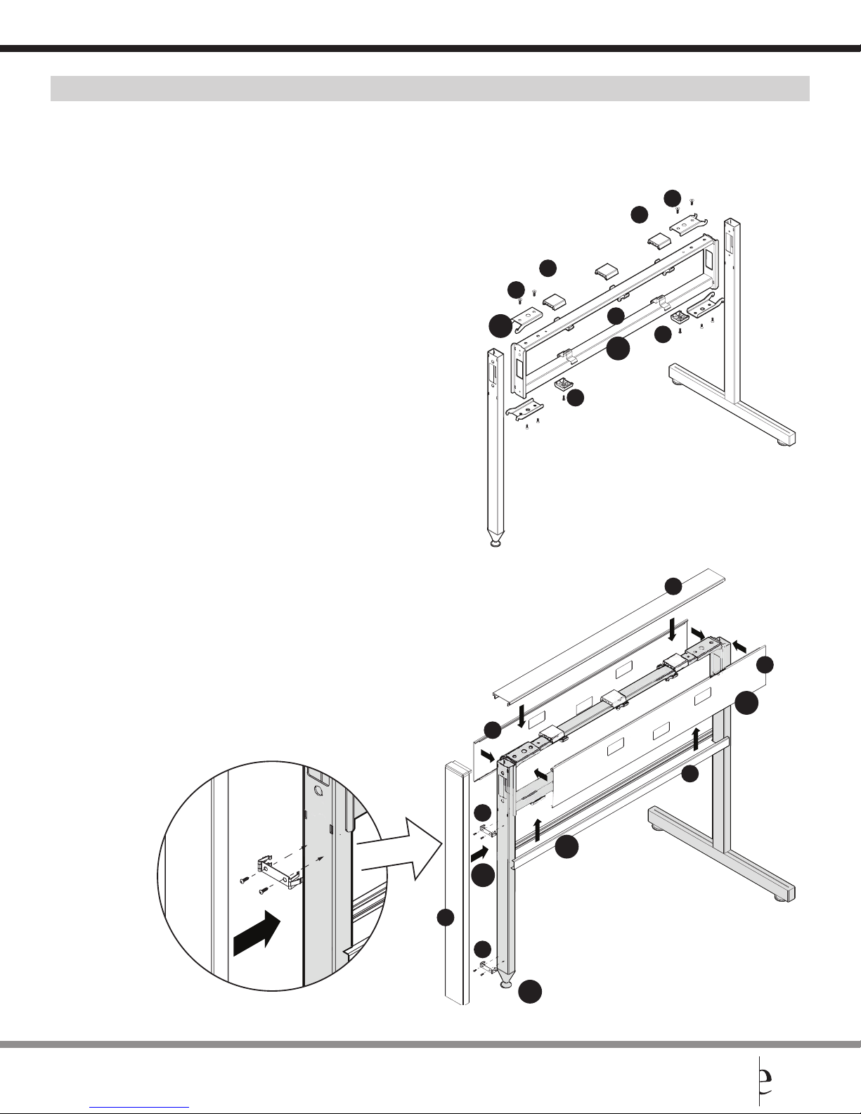
STEP 1: Connect the Power Beam (a) to the connectors using four clamps (b).
Two at the bottom, two at the top.
STEP 2: Attach the plastic blocks (c) to the bottom, and the spacers (d) to the top of the Power Beam.
*The plastic blocks (c) are to be attached with screws, while the spacers (d) come with an adhesive.
STEP 3: Add a raceway cover (e) on either side of the Power Beam.
STEP 4: Install bottom trim (f) and top trim (g).
STEP 5: Install the spring clips (h) using the supplied self drilling screws and snap on the end trims (i).
STEP 6: Adjust levelers as needed.
d
b
b
d
2
a
c
1
c
g
e
3
e
f
h
4
5
i
h
6
Evolve Customer Support available at 856.552.4000, 888.827.2500, from 8:30 am - 5:30 pm Eastern time, or fax at 856.552.4001.
4 evolvefurnituregroup.com
Page 5
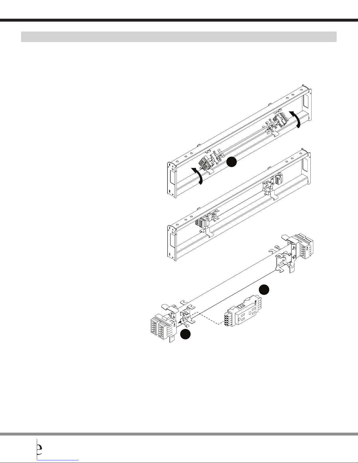
Power Distribution Housing
STEP 1: Insert the power distribution housing at an angle with the tabs facing down,
into the corresponding slots. Push it in until it clicks.
STEP 2: Position the receptacle into the mounting bracket on the power distribution housing.
There is an arrow and letter “N” to indicate which way is up.
STEP 3: Slide it towards the assembly connectors. Be sure the parts are fully seated to assure
proper electrical connection and the spring clips are properly engaged for mechanical security.
POWER BEAM INSTALLATION GUIDELINES
1
evolvefurnituregroup.com 5
2
3
Evolve Customer Support available at 856.552.4000, 888.827.2500, from 8:30 am - 5:30 pm Eastern time, or fax at 856.552.4001.
Page 6
POWER BEAM INSTALLATION GUIDELINES
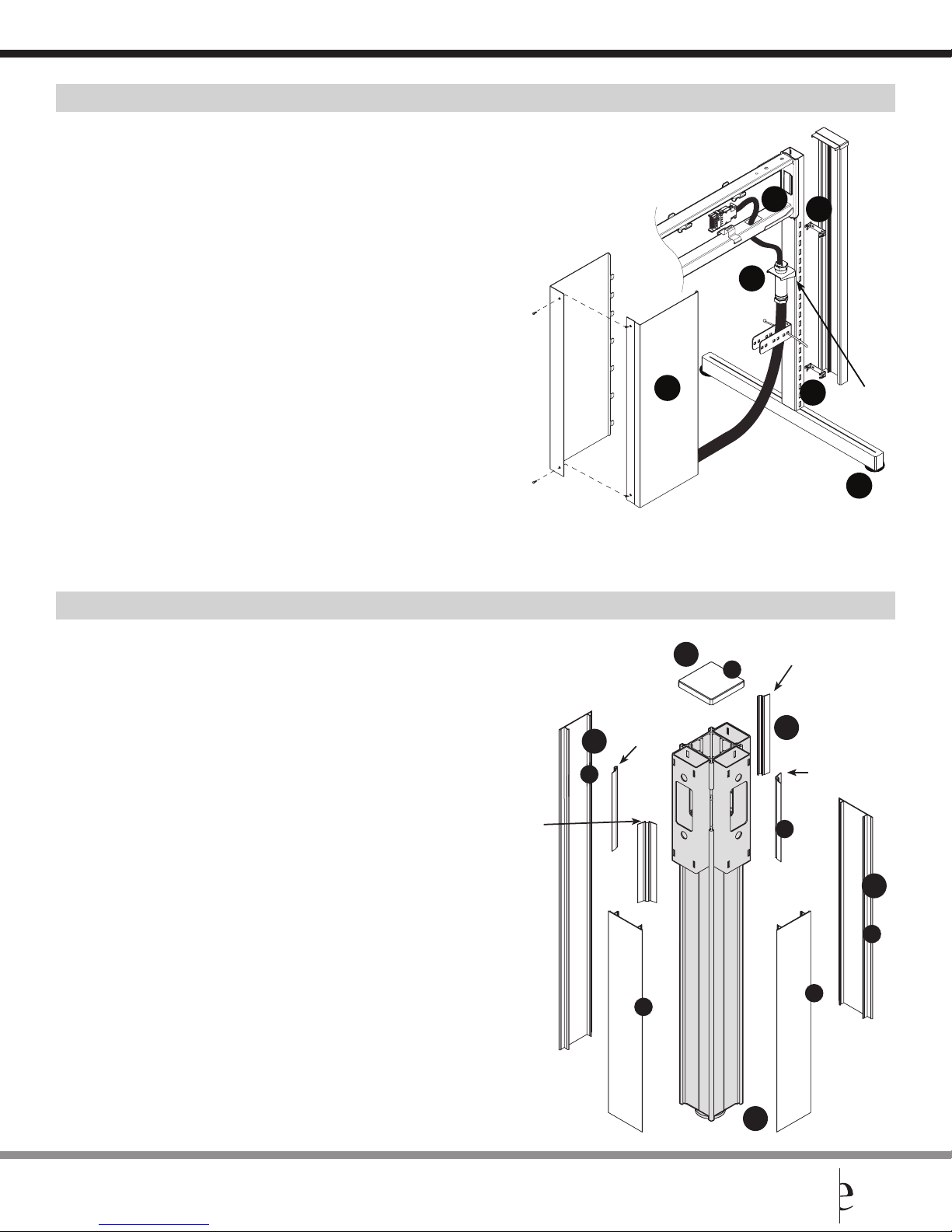
Slots for Base
Base Feed and Base Feed Cover
STEP 1: Hang the base feed on the slots above the “U” bracket and secure it with the provided zip tie.
STEP 2: Run the flexible portion of the feed through the opening in the bottom of the Power Beam.
STEP 3: Add the base feed cover and secure it using the two provided screws.
STEP 4: Snap on two spring clips to accept the end trim with end cap.
STEP 5: Adjust levelers as needed.
Note: There must be only one power feed entry into each cluster of stations.
Connection to the building supply must be done only by a licensed electrician,
and in accordance with applicable codes and regulations.
Do not connect or disconnect components while the system is under load!
Disconnect the main power before servicing or reconfiguration
2
4
1
Base Feed and Base Feed Cover
STEP 1: Install the long fl at trims (a) by snapping them on the exposed sides of the post.
STEP 2: Snap on the shorter fl at trims (b) on the post, below the power beam.
STEP 3: Press in the PVC slot covers (c) between the connectors. Tear off the fl exible side of
the PVC slot cover when inserting it between the long trim and the connector.
STEP 4: Install the post top cap (d).
STEP 5: Adjust the leveler as needed.
Do not tear off
fl exible side
1
a
Tear off
fl exible side
3
4
Feed bracket
5
4
d
Tear off
fl exible side
3
Do not tear off
fl exible side
c
2
b
b
Evolve Customer Support available at 856.552.4000, 888.827.2500, from 8:30 am - 5:30 pm Eastern time, or fax at 856.552.4001.
6 evolvefurnituregroup.com
5
b
Page 7
POWER BEAM INSTALLATION GUIDELINES
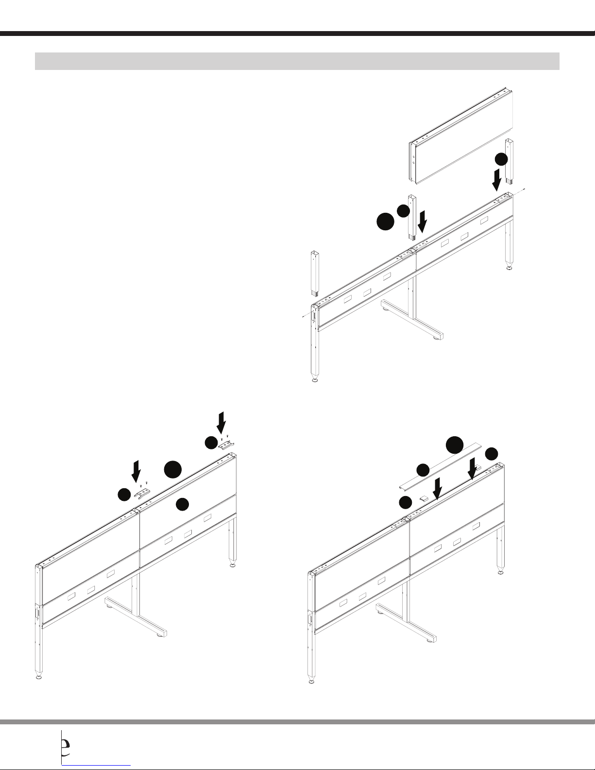
Power Beam - Extension Modules (Over Panels)
*Remove or do not install the plastic spacers (d). Remove or do not install the top trim yet (e).
STEP 1: Insert the extension connector (a) and secure it in place using the provided screw. Post extensions work the same way.
STEP 2: Slide in the module (b) and attach it to the extension connectors using the clamps (c).
STEP 3: Add two plastic spacers (d) on top and snap on the top trim (e).
1
a
a
c
3
d
2
e
c
b
d
evolvefurnituregroup.com 7
Evolve Customer Support available at 856.552.4000, 888.827.2500, from 8:30 am - 5:30 pm Eastern time, or fax at 856.552.4001.
Page 8
POWER BEAM INSTALLATION GUIDELINES
Privacy Glass Installation Instructions
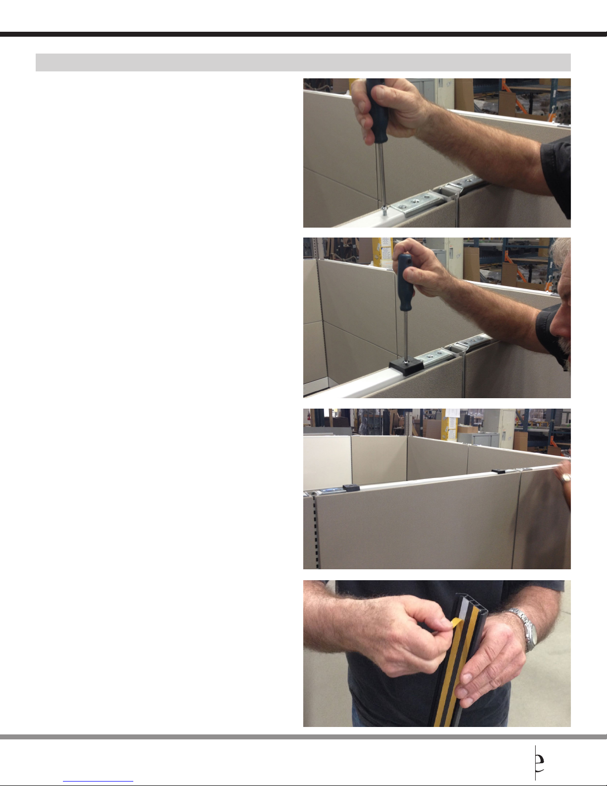
1. Remove screw
2. Install block and screw back using the same screw.
It is important to start the installation from the
middle panel.
3. Blocks installed
4. Peel o double sided tape
Evolve Customer Support available at 856.552.4000, 888.827.2500, from 8:30 am - 5:30 pm Eastern time, or fax at 856.552.4001.
8 evolvefurnituregroup.com
Page 9
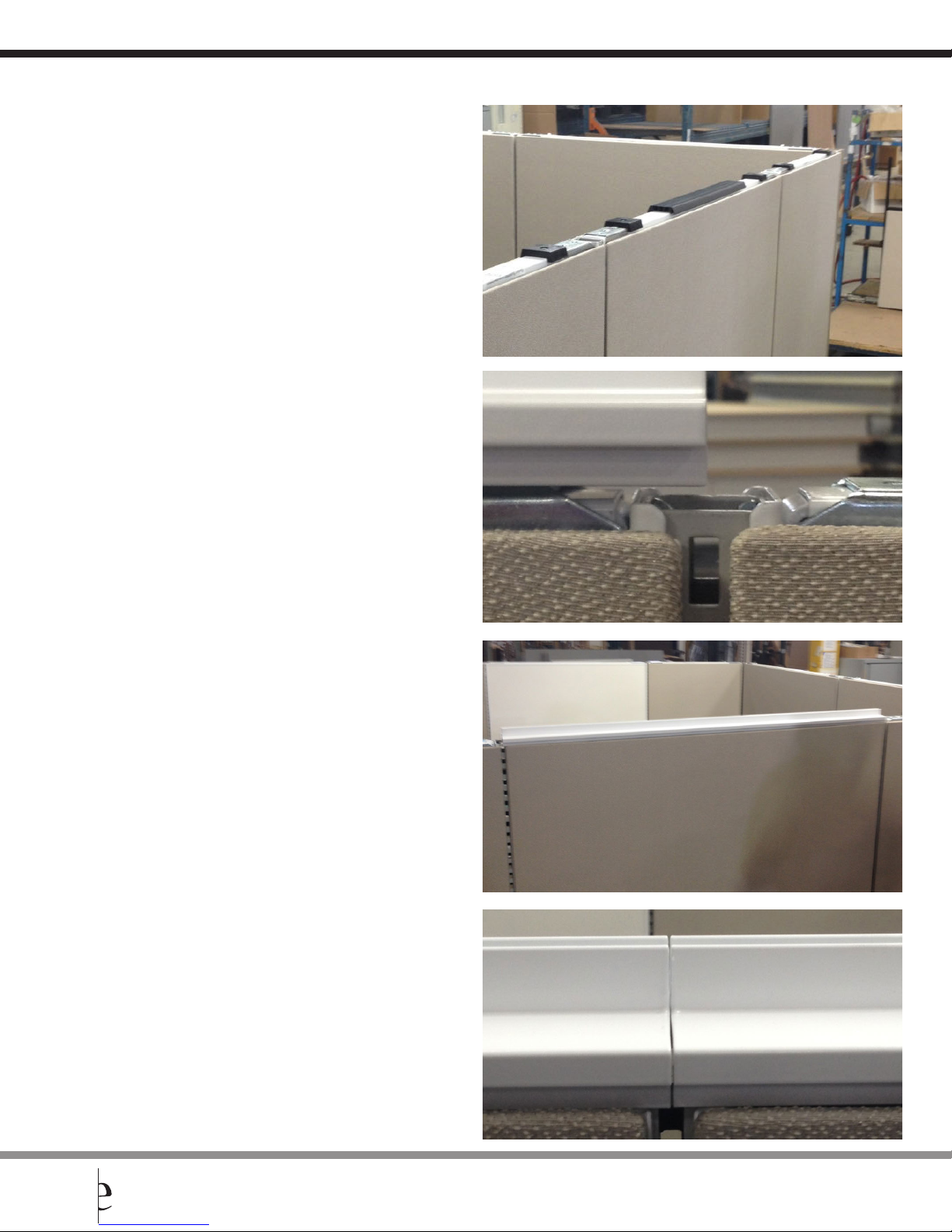
5. Install PVC spacer in the middle
6. Locate top trim and adjust sideways to the
middle of the slot
POWER BEAM INSTALLATION GUIDELINES
7. Snap on block
8. Install next top trim while ensuring that both
trims are fully aligned
evolvefurnituregroup.com 9
Evolve Customer Support available at 856.552.4000, 888.827.2500, from 8:30 am - 5:30 pm Eastern time, or fax at 856.552.4001.
Page 10
POWER BEAM INSTALLATION GUIDELINES
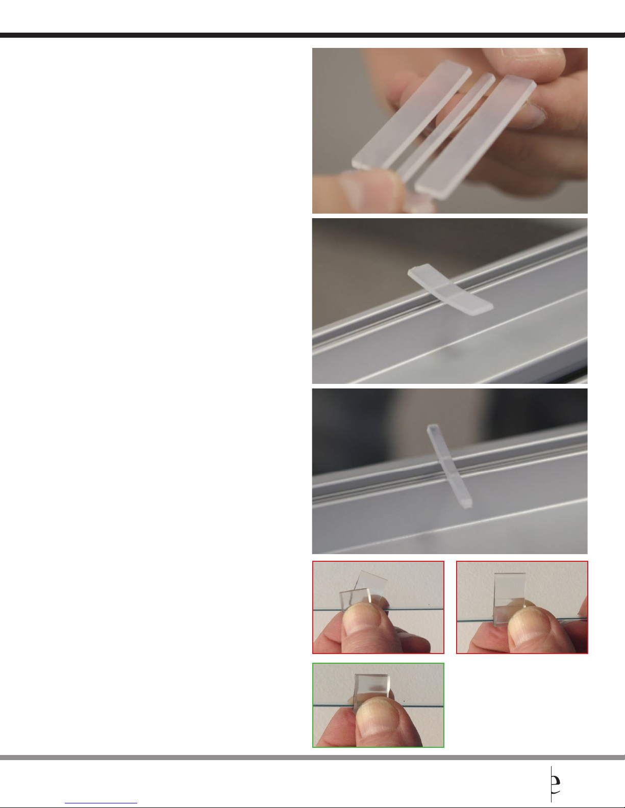
9. Plastic seal with grooves on the top side
For ease of installation, use 1/2” plastic seal
10. Place plastic seal on the head of the block screw
with grooves facing down. Adjust the plastic seal
symmetrically on the top of the trim on both sides.
11. Place thin plastic seal in middle of trim
Incorrect plastic seal installation
Correct plastic seal installation
Evolve Customer Support available at 856.552.4000, 888.827.2500, from 8:30 am - 5:30 pm Eastern time, or fax at 856.552.4001.
10 evolvefurnituregroup.com
Page 11
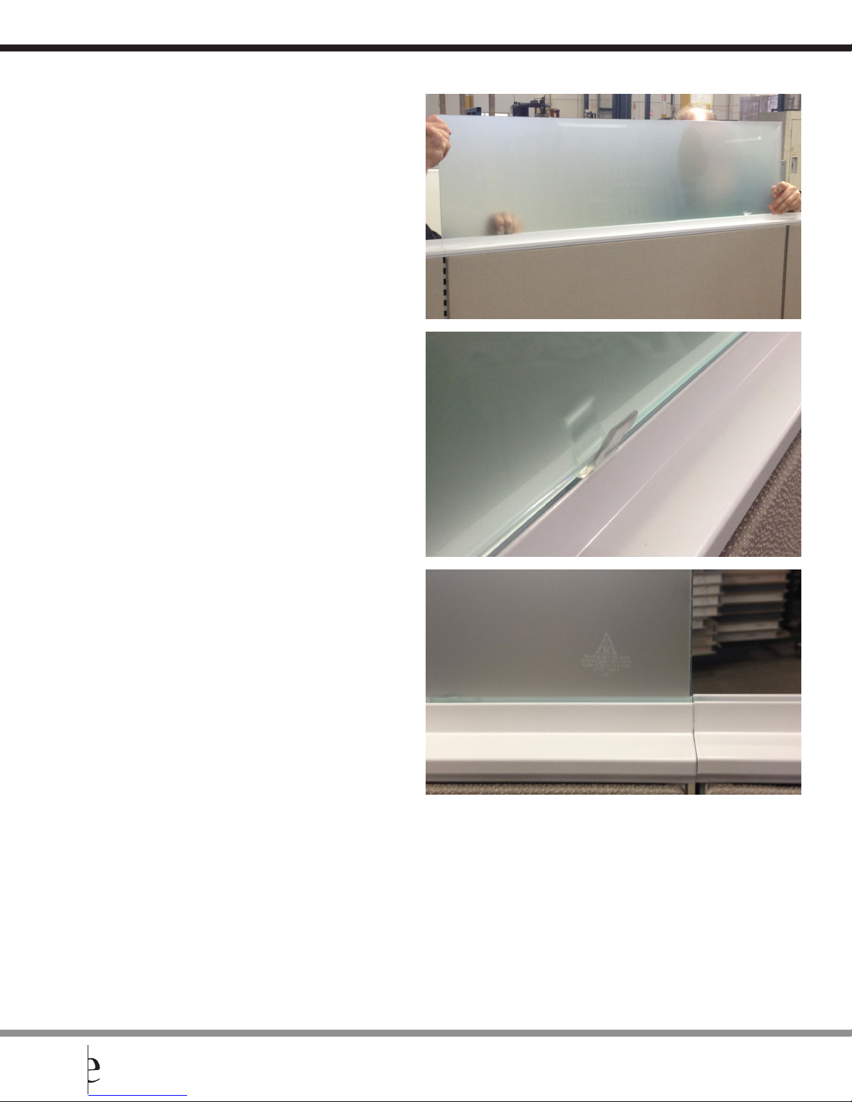
12. Hold privacy glass from both ends (2 people) and
install privacy glass ensuring that the glass seal is
fully aligned
13. If glass seal slides o place, pull glass up and
re-install as indicated in the previous step
POWER BEAM INSTALLATION GUIDELINES
14. Logo should always be consistently on the same
bottom corner. Ensure consistency with having the
shiny sides of the privacy glass on the same side
evolvefurnituregroup.com 11
Evolve Customer Support available at 856.552.4000, 888.827.2500, from 8:30 am - 5:30 pm Eastern time, or fax at 856.552.4001.
Page 12
POWER BEAM INSTALLATION GUIDELINES
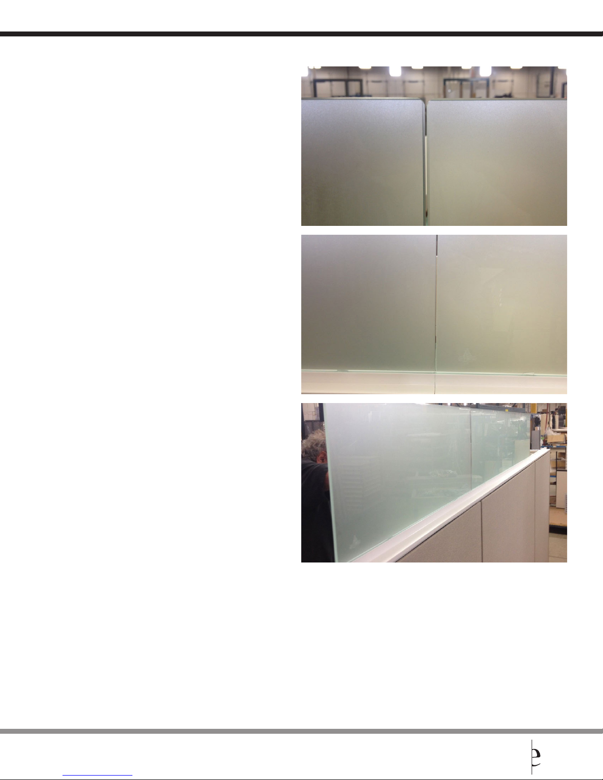
15. Ensure that the 2 adjacent privacy glass pieces
are aligned and a tight gap is left between
the 2 edges (3/32”)
16. Installation of privacy glass is complete with
shiny side out and log on the bottom left corner
Evolve Customer Support available at 856.552.4000, 888.827.2500, from 8:30 am - 5:30 pm Eastern time, or fax at 856.552.4001.
12 evolvefurnituregroup.com
Page 13
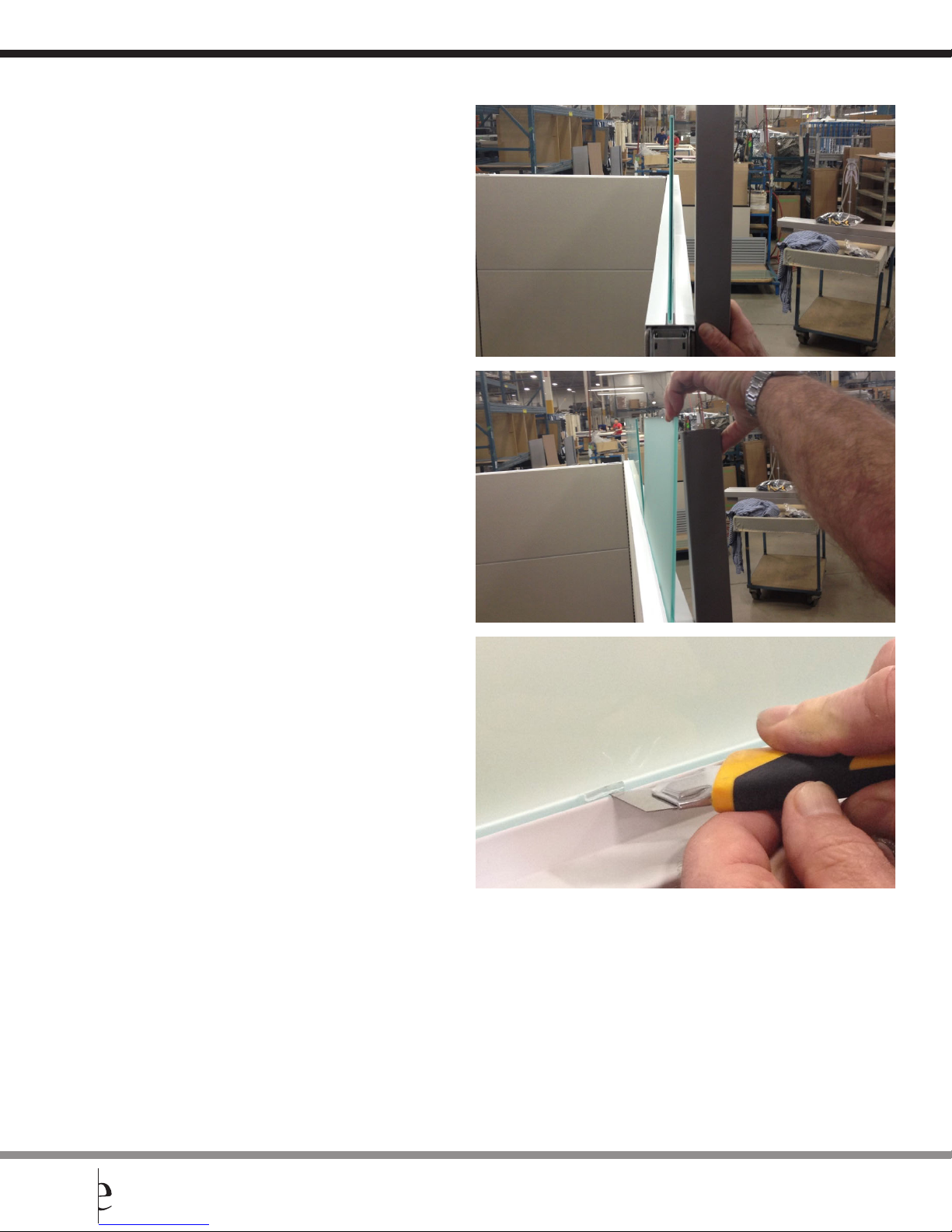
17. Check the squareness of glass
18. If needed, pull in the opposite direction
and check again
POWER BEAM INSTALLATION GUIDELINES
19. When installation is fully satisfactory, cut
protruding plastic seal with exacto knife
evolvefurnituregroup.com 13
Evolve Customer Support available at 856.552.4000, 888.827.2500, from 8:30 am - 5:30 pm Eastern time, or fax at 856.552.4001.
Page 14

Evolve Furniture Group
17 West Stow Rd. P.O. Box 562 Marlton, New Jersey USA 08053 T 856•552•4000 888•827•2500 F 856•552•4001 evolvefurnituregroup.com
 Loading...