

Page 1
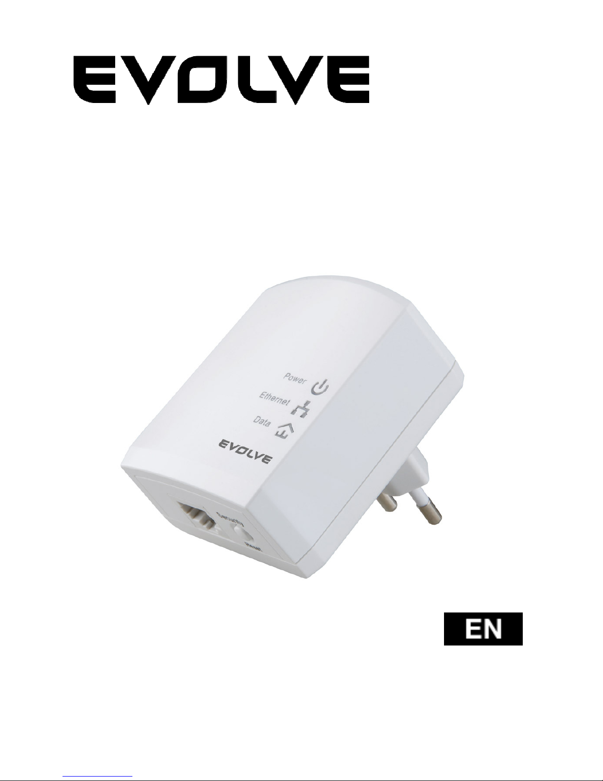
PL200M
200Mbps powerline adapter
User Manual
Page 2

129
Content
1 Introduction ........................................................................... 130
1.1 System Requirements ....................................................... 130
1.2 Packing List .................................................................. 130
2 Safety Precautions ................................................................... 131
3 Getting to Know the Adapter ....................................................... 132
3.1 Ethernet Port ................................................................ 132
3.2 Buttons ....................................................................... 132
3.3 LEDs ........................................................................... 133
4 Installing Powerline Utility ......................................................... 135
5 How to Use Powerline Utility ....................................................... 143
5.1 Main tab ...................................................................... 143
5.2 Information Tab ............................................................. 150
5.3 About Tab..................................................................... 151
6 How to Use the Security/Reset Pushbutton ...................................... 153
6.1 Forming a HomePlug AV logical network ................................ 153
6.2 Joining a Network ........................................................... 154
6.3 Leaving a Network .......................................................... 155
7 How to Enter and Exit from the Standby Mode .................................. 156
7.1 Entering the Standby Mode ................................................ 156
7.2 Exiting From the Standby Mode ........................................... 156
8 How to Improve the Transmission Capacity ...................................... 157
Appendix A Specifications ............................................................ 158
Appendix B Acronyms and Abbreviations .......................................... 159
Page 3

130
1 Introduction
EVOLVE PL200M (also called “the device” hereinafter) is a low power consumption
PLC device. It can transmit network data in the household powerline. The device
is compatible with the latest requirements of the EUP Directive. When the device
enters the lower power consumption mode, the consumption is less than 0.5W.
The device can detect 200Mbps PLC-Ethernet bridge devices in the powerline
network, measure data rate performance, ensure the security of the powering
network, and perform system diagnosis.
1.1 System Requirements
Operating System Windows 98SE, Windows 2000, Windows
ME, Windows XP 32/64 bit and Windows
Vista 32/64bit
CPU Intel Pentium III or higher and clock rate
faster than 2.0 GHz are recommended.
RAM At least 128 MB
Screen Resolution Any resolution
Free Disk Space At least 20 MB
Network Interface At least one fast Ethernet (100 Mbps)
network interface card (NIC) and one
Ethernet cord
1.2 Packing List
1 x x Mini-PLC Devices
1 x CD-ROM
1 x RJ45 Ethernet cables
Page 4

131
2 Safety Precautions
This device is intended for connection to the AC powerline. For installation
instructions, please refer to the installation section of this guide. The following
precautions should be taken when using this product.
Follow all the warnings and instructions marked on the product.
Unplug the device from the wall outlet before cleaning. Use a damp cloth
for cleaning. Do not use liquid cleaners or aerosol cleaners.
Keep the device away from a radiator or heat register.
Do not use an extension cord between the device and the AC power source.
Only professional technicians should service the device. Opening or
removing covers may result in exposure to dangerous voltage points or
other risks.
Unplug the device from the wall outlet and refer to professional service
personnel for the following conditions:
– If liquid has been spilled into the product
– If the device has been exposed to rain or water
– If the device does not operate normally when the operation
instructions are followed.
– If the device exhibits a distinct change in performance
Page 5
132
3 Getting to Know the Adapter
3.1 Ethernet Port
Ethernet: Ethernet port. Connect one end of an Ethernet network cable to PLC’s
Ethernet port and the other end to your computer or other Ethernet-enabled
network device.
3.2 Buttons
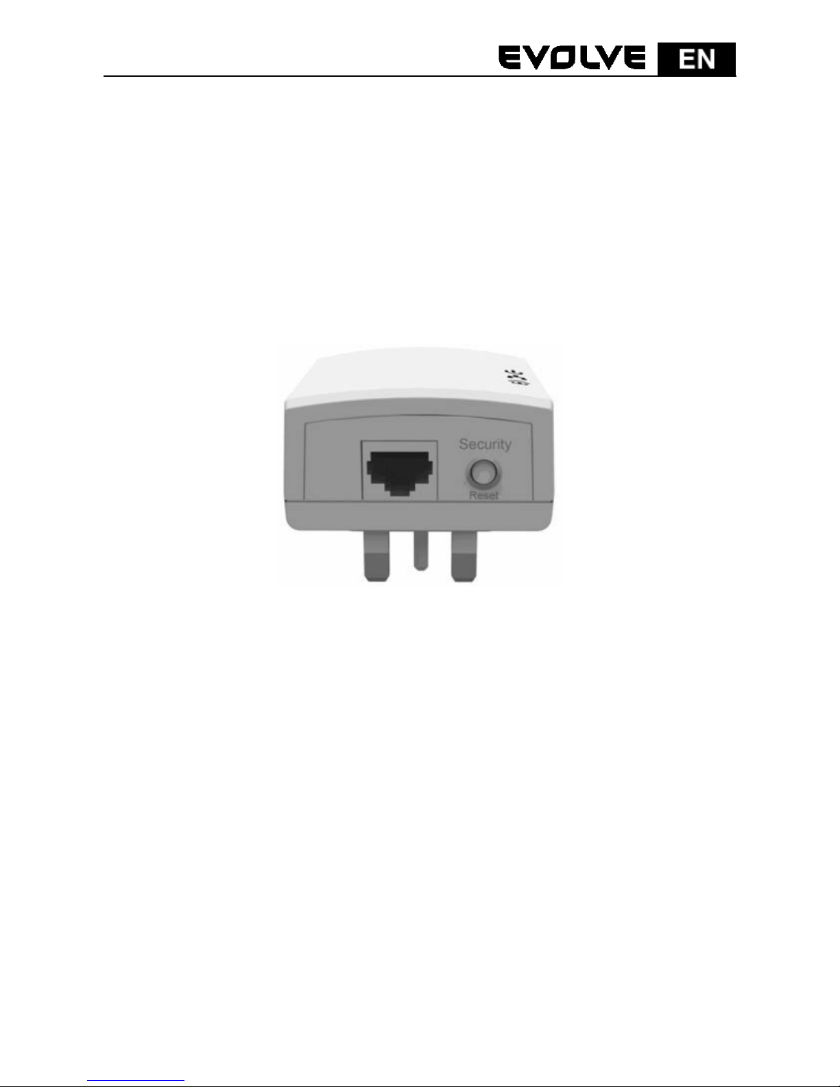
Figure 1: Side panel of the device
Security/Reset: Set the status of the device members or restore the factory
default settings.
Factory Reset: Press and hold the Security/Reset button for 10 seconds.
Exit the existing AVLN: Press and hold the Security/Reset button for 5-8
seconds, and then release it.
Make the adapter a member of the existing AVLN: Press and hold the
Security/Reset button for 1-3 seconds. For more details, see Chapter 6.
Page 6
133
3.3 LEDs
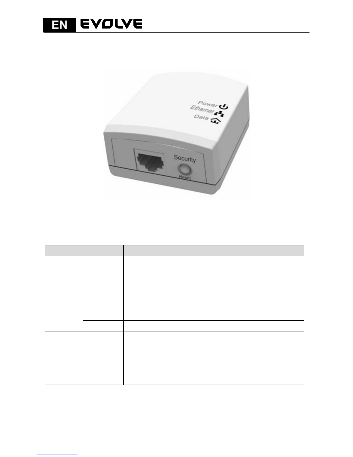
There are 3 LEDs on the front panel to indicate the adapter status.
Figure 2: Top view
The following table describes the LEDs on the device.
LED Color Behavior Description
Power
Green On
The adapter is supplied with power and
running normally.
Green Blink
System is in the process of security
setup.
Orange
Blink every
4 seconds
System enters the standby mode.
- Off The adapter is powered off.
Ethernet Green On
The adapter is connecting to other
devices via the Ethernet port but not
communicating with them.
Page 7

134
Green Blink
The adapter is receiving or transmitting
data via the Ethernet port.
- Off
The device is not connecting to other
devices via the Ethernet interface.
Data
Green/
Orange/
Red
On
The device has connected to the power
line network.
Green/
Orange/
Red
Blink
The Data LED color varies with the
physical rate.
Green: Link Rate > 40 Mbps
Orange: 20 Mbps < Link Rate <40
Mbps
Red: Link Rate < 20 Mbps
- Off
The adapter has not found any other
compatible powerline devices that use
the same encryption key.
Note:
The Power, Ethernet and Data indicators blink on and off when the device is
powered on. At that moment, the Ethernet indicator is green, and the Power
and Data indicators are orange
Page 8
135
4 Installing Powerline Utility
Powerline Utility is a configuration management tool for BCM60321-chip devices
developed based on HomePlugAV and Xtendnet
TM
. It can trace and scan GGL
devices and BCM60321-chip devices in the same network.
Before installing Powerline Utility of PL200M, uninstall other Powerline Utility on
your computer.
To properly run Powerline Utility, first install WinPcap. For more information
about WinPcap, visit http://www.winpcap.org
.
Do as follows to install Powerline Utility:
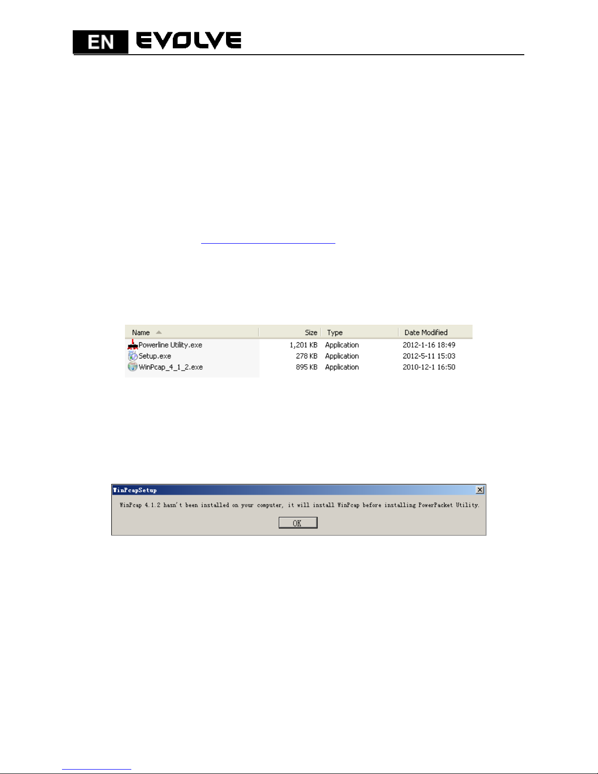
Step 1 Insert the CD into the CD drive. Open the PLC 200M Utility Installation
folder and double-click Setup.exe to start installing Powerline Utility.
Figure 3: Open the CD folder
Step 2 If your computer has not been installed with WinPcap, WinPcap will
automatically be installed first. Click OK to start install WinPcap. See
the following figure.
Figure 4: Prompt for installing WinPcap
If your computer has been installed with the latest WinPcap, Powerline Utility will
be installed directly. Proceed to step 11.
Page 9
136
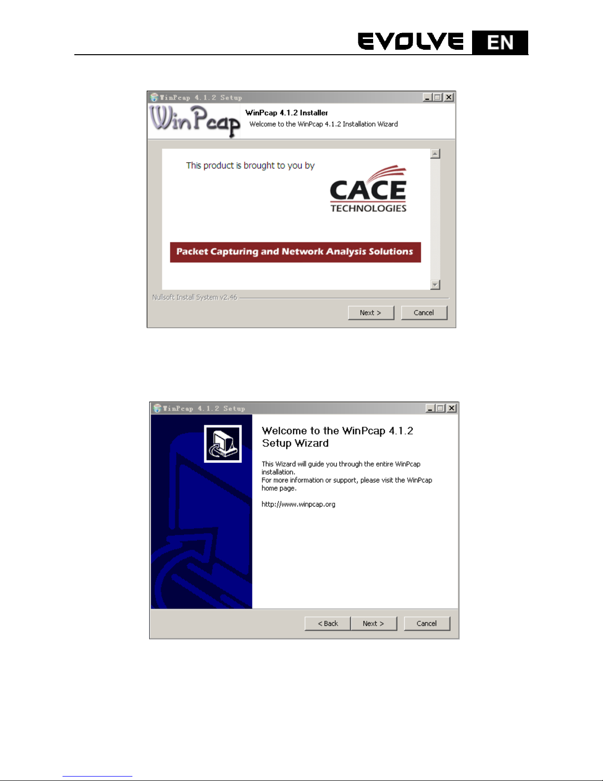
Step 3 Click Next to continue installation.
Figure 5: WinPcap installer
Step 4 Click Next to continue installation.
Figure 6: Setup wizard
Page 10
137
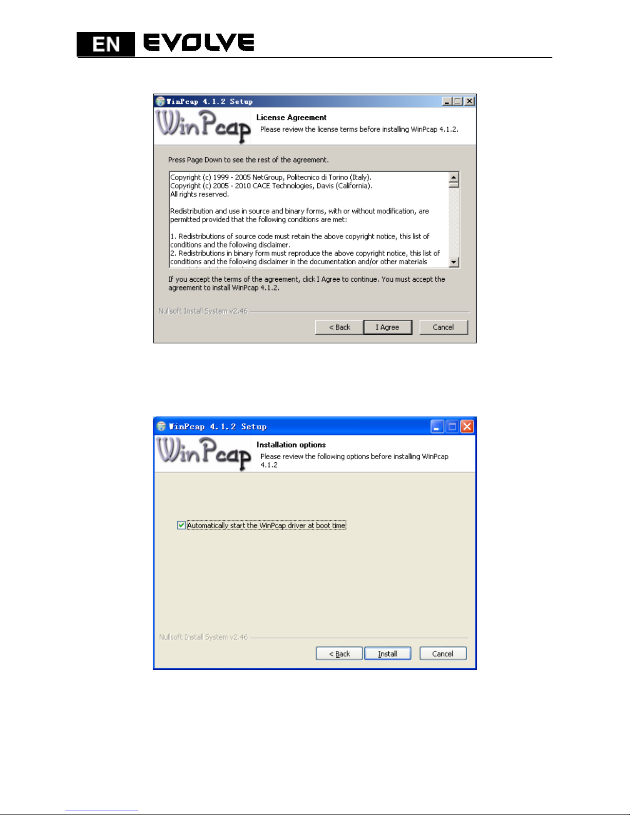
Step 5 Click I Agree to accept the license agreement of WinPcap.
Figure 7: License agreement
Step 6 Click Install to install WinPcap 4.1.2.
Figure 8: Install WinPcap 4.1.2
Page 11
138
Note:
If WinPcap of an earlier version has been installed in your computer, the
system notifies you to uninstall the earlier version when you try installing
WinPcap included in the CD.
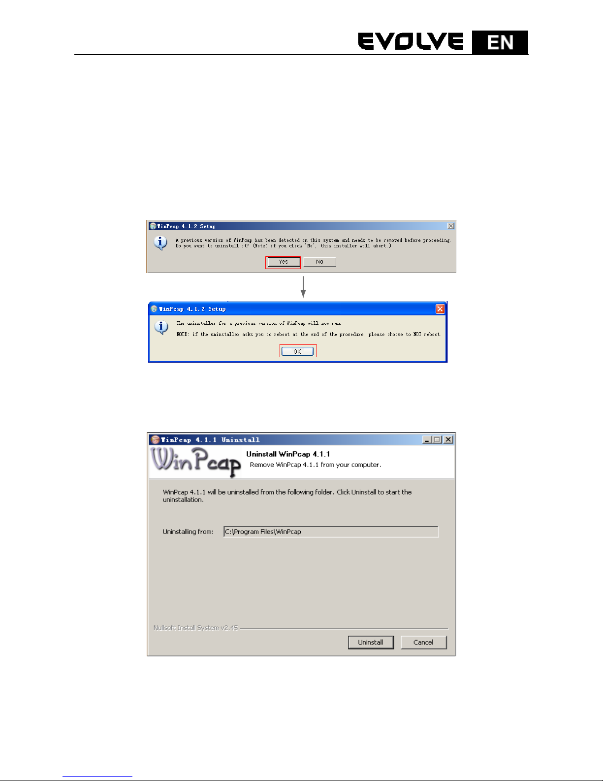
Step 7 If WinPcap of an earlier version has been installed in your computer,
the system notifies you to uninstall the earlier version when you try
installing WinPcap included in the CD. Click Yes.
Figure 9: Dialog box for uninstalling earlier WinPcap
Step 8 Click Uninstall to start uninstallation.
Figure 10: Uninstalling earlier WinPcap
Page 12
139
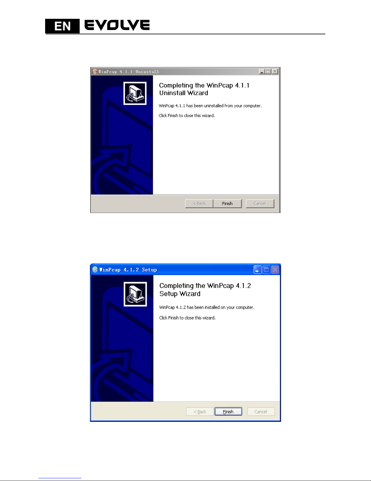
Step 9 Click Finish to complete uninstalling earlier WinPcap.
Figure 11: Complete uninstalling earlier WinPcap
Step 10 Click Finish to complete installing WinPcap and start to install
Powerline Utility.
Figure 12: Complete installing WinPcap
Page 13
140
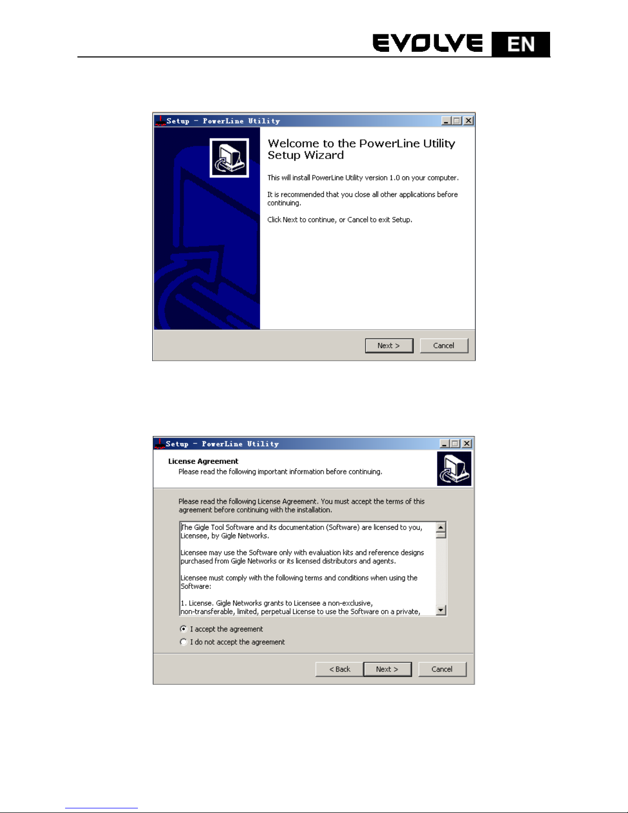
Step 11 Click Next to follow Powerline Utility setup wizard.
Figure 13: Setup Wizard for Powerline Utility
Step 12 Select I accept the agreement. Click Next to continue installation.
Figure 14: License agreement
Page 14
141
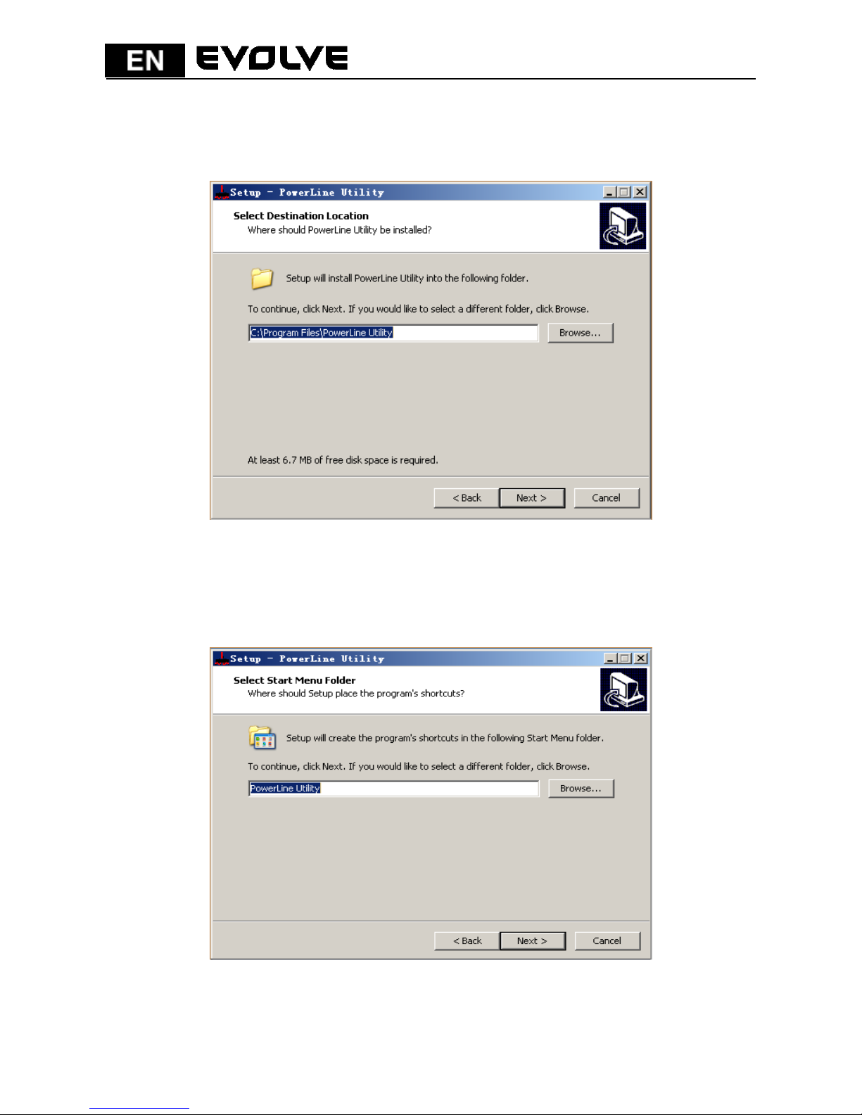
Step 13 Click Browse… to change the path for installing Powerline Utility. The
default installation path is C:\Program Files\Powerline Utility. Click
Next.
Figure 15: Select an installation path
Step 14 Create a shortcut in the Start Menu folder. Click Browse… to select a
folder to place the shortcut. Click Next to continue the installation.
Figure 16: Select a folder to place the shortcut
Page 15
142
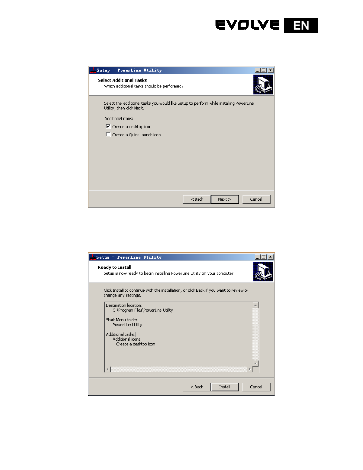
Step 15 Select Create a desktop icon or Create a Quick Launch icon if necessary.
Click Next..
Figure 17: Select additional tasks
Step 16 Click Install to start installing Powerline Utility.
Figure 18: Ready to install
Page 16
143
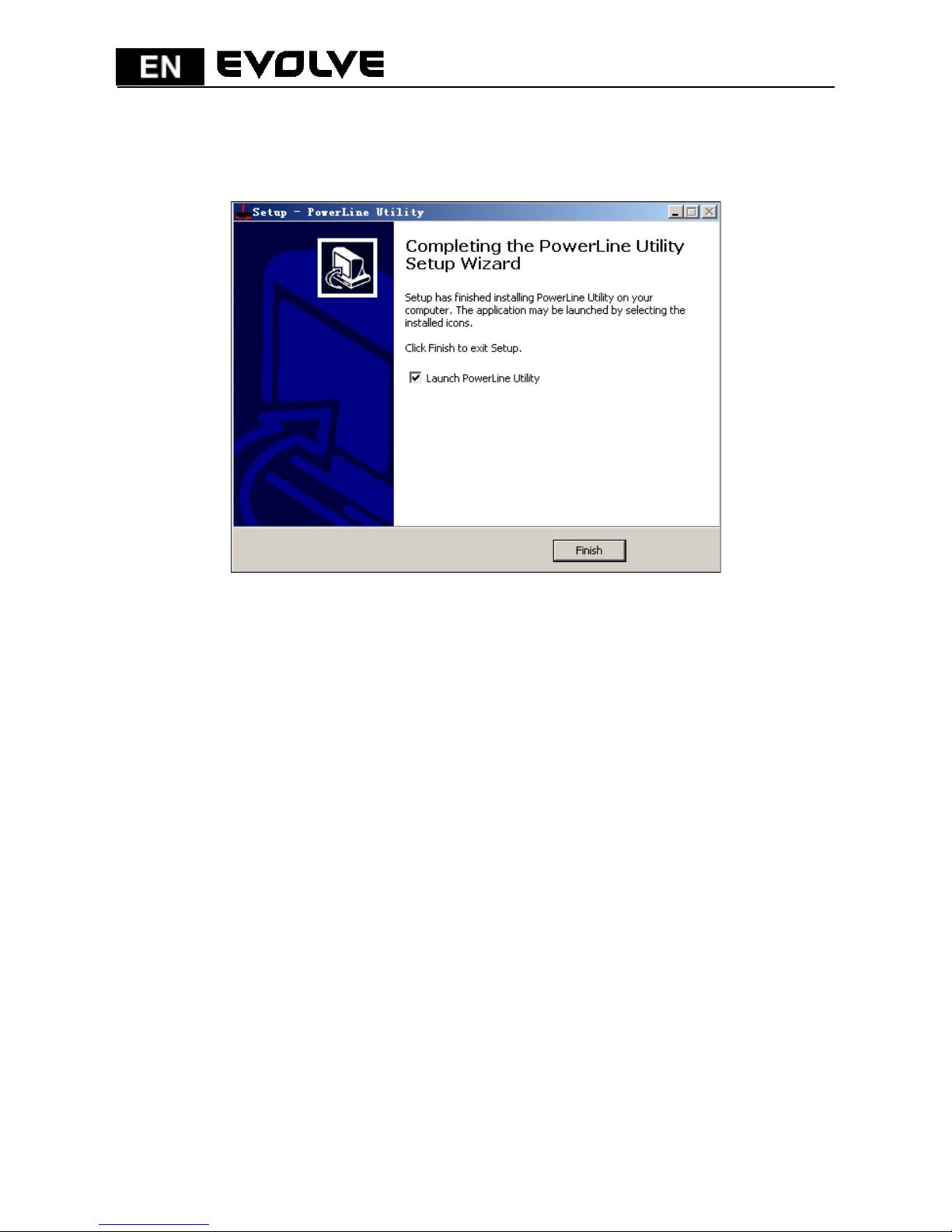
Step 17 Click Finish to complete installing Powerline Utility. If you select
Launch Powerline Utility, Powerline Utility is automatically run after
it is successfully installed.
Figure 19: Complete the installation
5 How to Use Powerline Utility
Click the icon in the desktop or quick launch bar to open Powerline Utility.
5.1 Main tab
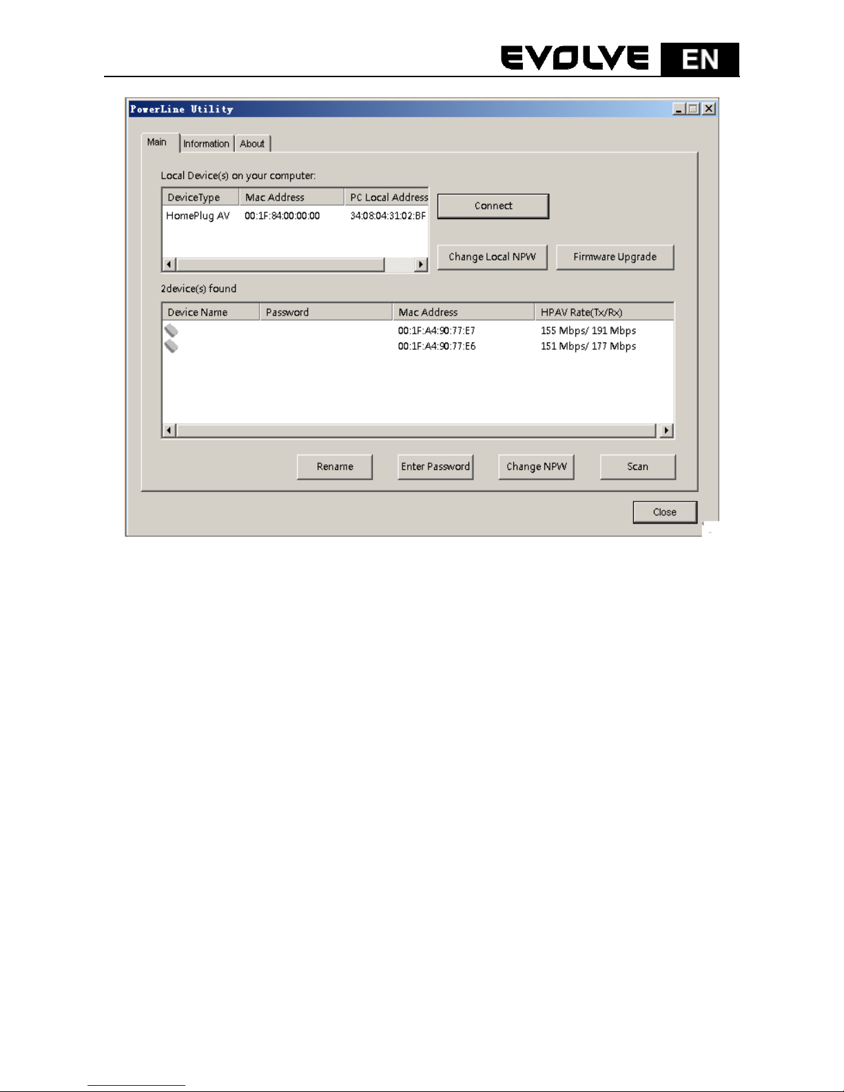
The Main screen provides a list of all powerline devices logically connected to the
computer. The top panel shows the local HomePlugAV devices connected to the
network interface card (NIC) of the computer or remote devices that pass
verification.
Click Connect, and Powerline Utility automatically scans the powerline
periodically for other HomePlugAV devices connected to it. If no local
HomePlugAV device is discovered, the screen displays “0 device(s) found”.
Page 17
144
Figure 20: Main tab
Note:
Usually, only one HomePlugAV device will be detected and displayed on the
top panel of the screen. However, more than one HomePlugAV devices will
be detected if your computer has multiple NICs.
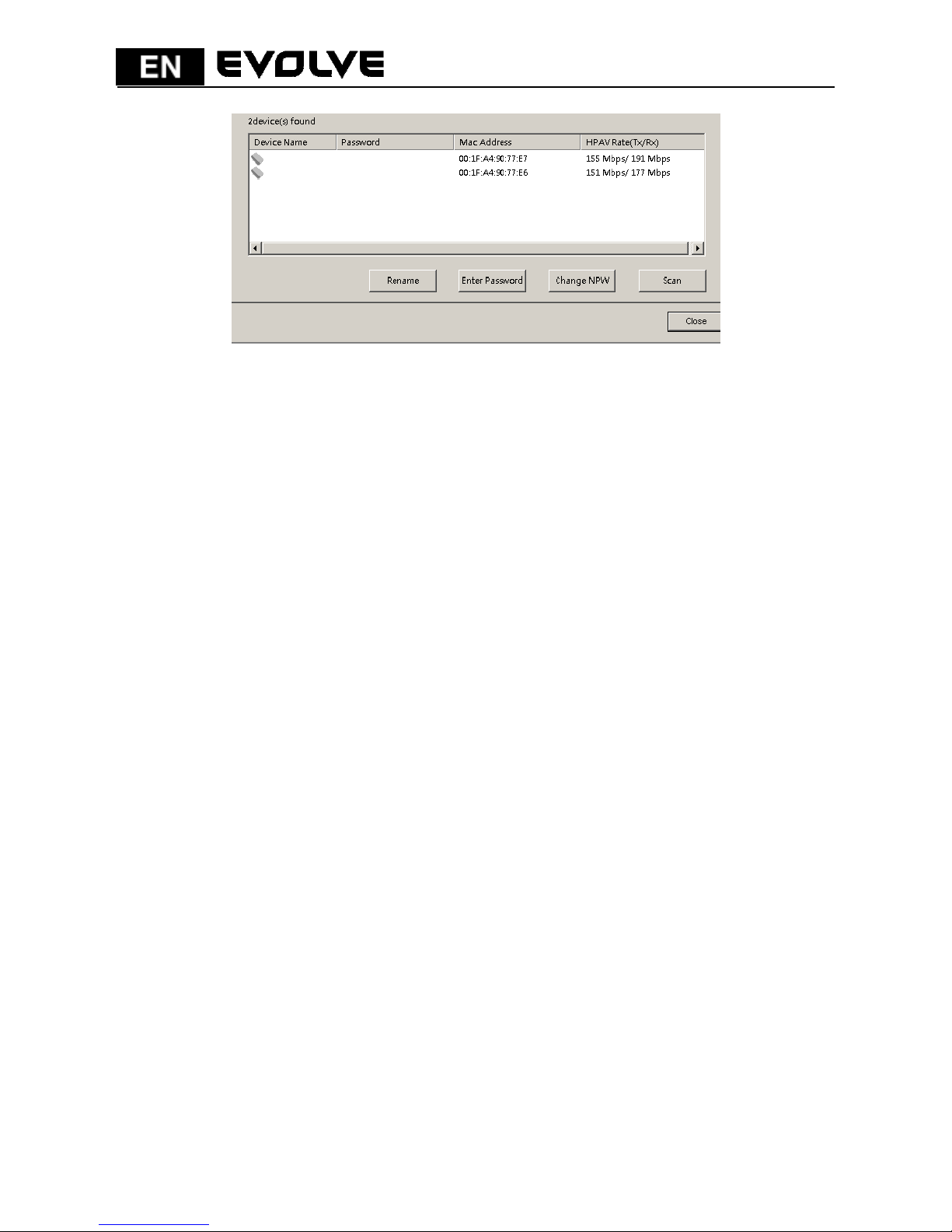
The lower panel displays all the HomePlugAV remote devices discovered in the
current logical network. The total number of remoter devices connected in the
same network is displayed above the remote device panel.
Page 18
145
Figure 21: Lower panel of the Main tab
The following information is displayed for all the devices that appear in the lower
panel.
Device Name
This column shows the default device name, which may be modified. To change
the name, click Rename.
Mac Address
This column shows the MAC addresses of the remote devices.
Password
By default, this column is blank. You can click Enter Password to enter it. For
some operations (for example, changing network passwords), you must first get
devices’ password verified by entering correct passwords.
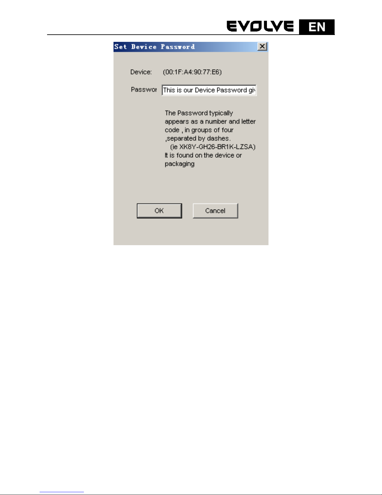
The steps for entering the password of the device are as follows:
Step 1 Click the device name to select the device in the lower panel.
Step 2 Click Enter Password. A dialog box appears, showing the device name
and password. The default password (DEK) is printed on labels on the
bottom of devices.
Page 19
146
Figure 22: Change the device’s password
Step 3 Click OK to verify the password.
This process might take a few seconds to get completed. If the password is
entered correctly, the device’s password shows in the Password column on the
lower panel. If a device is not found, a message appears, suggesting trying again.
Change NPW (Network Password)
The Change NPW button is used to remove a remote device from its
existing network by changing the NPW for the remote device. All devices
are shipped with a default NPW (“HomePlugAV”). Devices with the same
NPW are located in the same network.
Page 20
147
Note:
Only devices that have their password verified can be removed from a
network by clicking Change NPW. Before changing a device’s NPW, click
Enter Password to enter the device’s password to achieve verification.
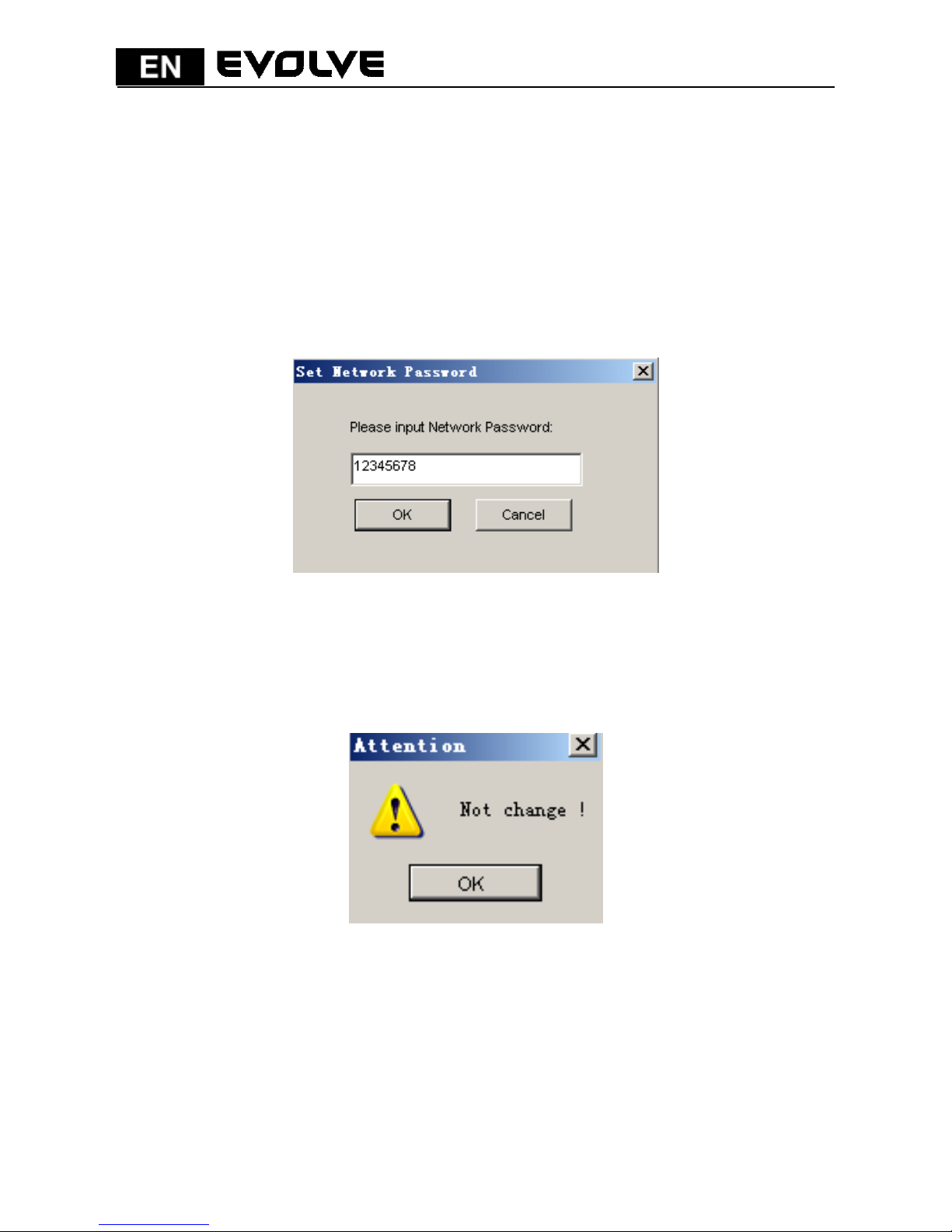
If the device is found and has its password entered correctly, enter a new NPW
different from the existing network in the Set Network Password dialog box
displayed. Then, the device is successfully removed from the network.
Figure 23: Change the network password
If a device does not have its password entered, a “Not change!” message appears.
You need to click Enter Password to enter the device’s password to achieve
verification first.
Figure 24: Not Change message
Page 21
148
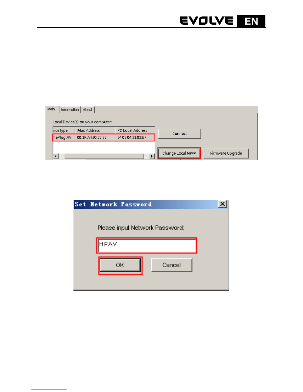
Change Local NPW
The Change NPW button is used to remove a local device from its existing
network or add a local device to another network by changing the NPW for the
local device. All devices are shipped with a default NPW (“HomePlugAV”). Devices
with the same NPW are located in the same network.
To remove a local device from its existing network:
Step 1 Select a local device in the top panel and click Change Local NPW.
Figure 25: Select a device name
Step 2 In the screen displayed, set a network password different from that of
the local device’s existing network.
Figure 26: Set a new network password
Step 3 Click OK.
After the network password for the local device is changed successfully, this local
device is removed from its existing network. Previous devices displayed on the
lower panel will disappear and devices with the same NPW as this local device will
appear on the lower panel.
Page 22

149
To add a local device into a network:
Step 1 Select a local device in the top panel and click Change Local NPW.
Step 2 In the screen displayed, set the network password the same as that of
the network this device is to add into.
Step 3 Click OK.
After the network password for the local device is changed successfully, this local
device is added into the target network. Previous devices displayed on the lower
panel will disappear and devices in the target network will appear on the lower
panel.
Scan
The Scan button is used to perform an immediate search for HomePlugAV devices
connected to the powerline network. By default, Powerline Utility automatically
scans every a few seconds and updates the displayed information.
Firmware Upgrade
The Firmware Upgrade button is used to upgrade the device firmware.
Note:
Only devices that have their password verified can achieve firmware
upgrade by clicking Firmware Upgrade.
The steps for upgrading firmware are as follows:
Step 1 Select a local device from the top panel.
Step 2 Click Firmware Upgrade.
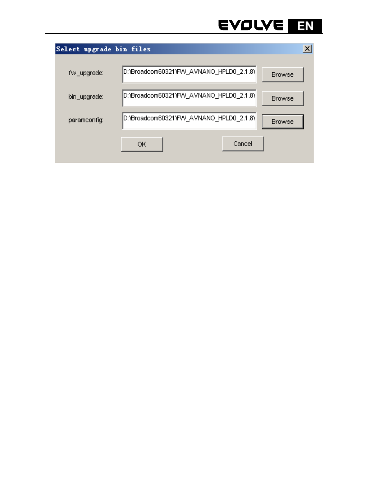
Step 3 Click Browse to choose a configuration file (fw_upgrade, bin-upgrade,
or paramconfig).
Page 23
150
Figure 27: Upgrade the device
Step 4 Click OK.
It takes several minutes to complete firmware upgrade. Do not interrupt the
upgrade process.
5.2 Information Tab
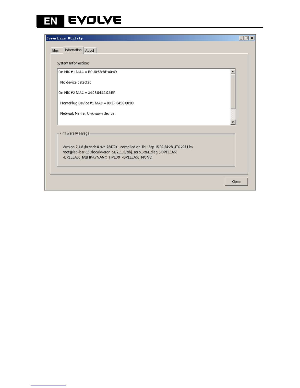
The Information screen shows the system information and the firmware version.
The upper panel shows technical data concerning software and hardware on the
host computer that are used to communicate through HomePlug on the powerline
network. It includes the following:
M AC address of all NICs connected to the host
MAC address of all devices connected locally to the host
network Name (NPW) of local devices
Software version
Firmware version (including release date and SVN date)
Vendor name
Page 24
151
Figure 28: Information tab (two NICs)
5.3 About Tab
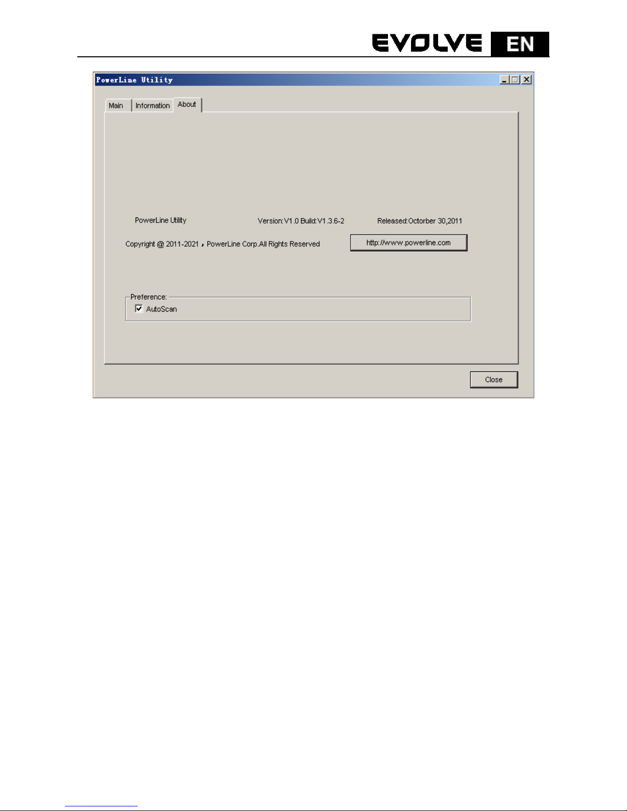
The About screen shows the software version and provides an html link to a
website, such as http://www.powerline.com. Clicking the Web address, you can
visit the website.
Page 25
152
Figure 29: About tab
Preferences
The lower panel displays options for turning the autoscan function on or off.
Page 26
153
6 How to Use the Security/Reset Pushbutton
This chapter describes how to use the Security/Reset pushbutton to add new
devices into or remove devices from a HomePlug AV logical network (AVLN).
You can monitor the operation progress and results by observing the Power LED
status.
6.1 Forming a HomePlug AV logical network
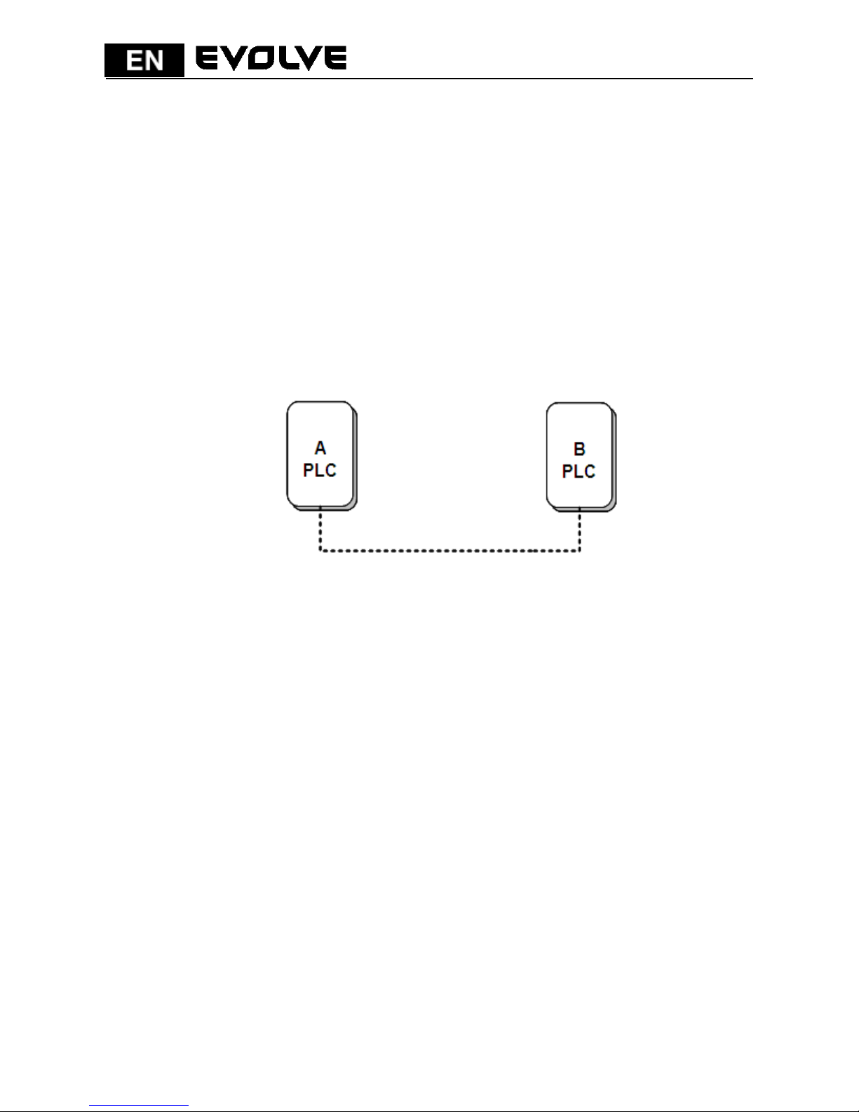
Scenario:
Devices A and B with different NPW values are connected to the same powerline.
Users want to use them to form a logical network.
Figure 30: Form a HomePlugAV network
Do as follows to form a logical network:
Step 1 Press the Security/Reset pushbutton on device A or B for 5-8 seconds.
The device will reset and restart with a random NMK.
Step 2 Press the Security/Reset button on device A for less than 3 seconds.
Step 3 Within 30 seconds, press the Security/Reset button on device B for less
than 3 seconds.
Step 4 Wait for connection to complete.
The power indicator on both devices will flash evenly at 1 second intervals until the
operation succeeds or fails. If the connection succeeds, the Power and Data
indicators on both devices illuminate steadily. If the connection fails, the Power
indicators on both devices keep steady on, but the Data indicators on both devices
are off. In that case, repeat steps 1-4.
Page 27
154
6.2 Joining a Network
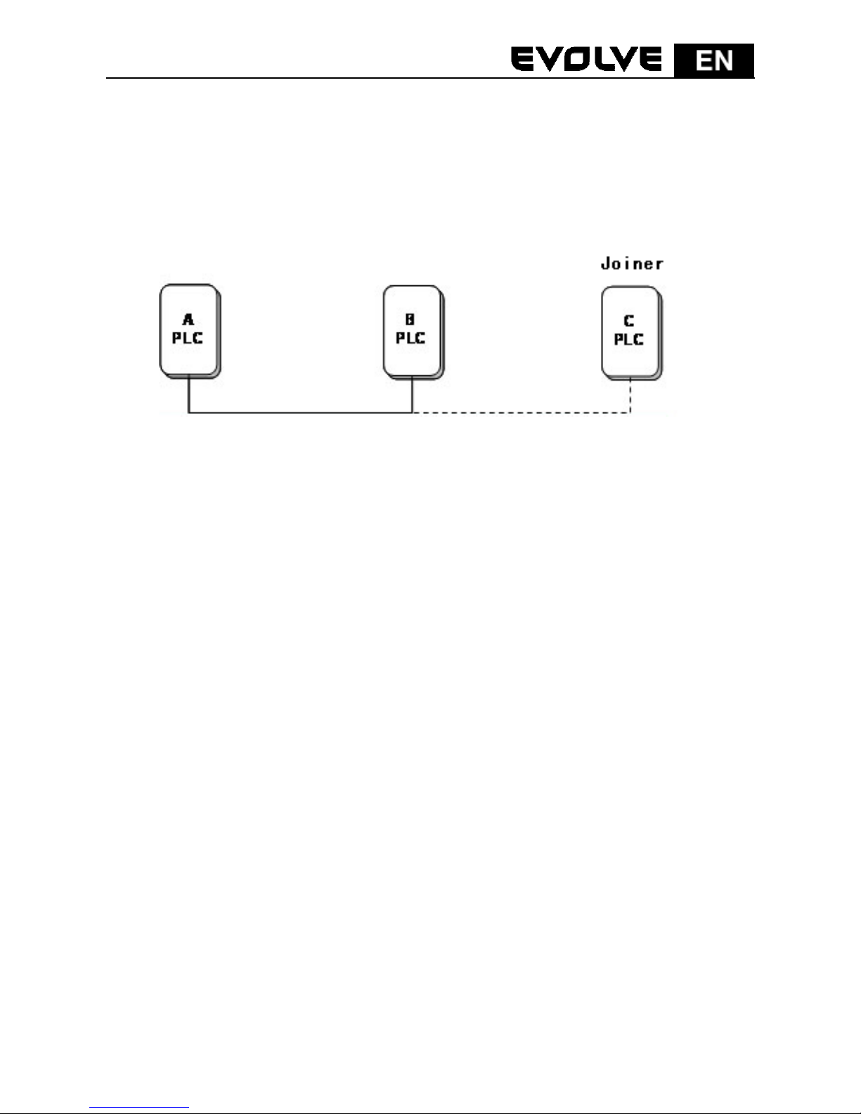
Scenario:
Devices A and B are located in network N. Users want to add device C (the joiner)
into network N. Any devices on network N can become the ‘adder’.
Figure 31: Join a HomePlugAV network
Do as follows to add device C to network N using the Security/Reset button:
Step 1 Press the Security/Reset pushbutton on device C (the joiner) for 5-8
seconds. The device will reset and restart with a random NMK.
Step 2 Press the Security/Reset button on device C (the ‘joiner’) for less than
3 seconds.
Step 3 Within 30 seconds, press the Security/Reset button on device A (or
device B) for less than 3 seconds.
Step 4 Wait for connection to complete.
The power indicator on both devices will flash evenly at 1 second intervals until
the operation succeeds or fails. If the connection succeeds, the Power and Data
indicators on both devices illuminate steadily. If the connection fails, the Power
indicators on both devices keep steady on, but the Data indicators on both
devices are off. In that case, repeat steps 1-4.
Page 28
155
6.3 Leaving a Network
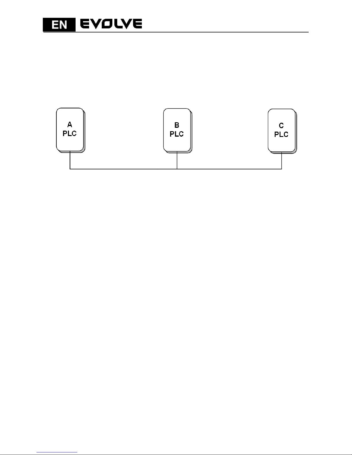
Scenario:
Device C is located in a network. Users want to remove device C (the ‘leaver’)
from its network.
Figure 32: Remove a device from a network
Do as follows to remove device C from network N:
Step 1 S Press the Security/Reset pushbutton on device C (the ‘leaver’) for 5-8
seconds. The device will reset and restart with a random NMK.
Step 2 Wait for reset to complete
The Power indicator on device C momentarily extinguishes during reset, blinks
during restart, and then illuminates steadily.
After device C is removed from its existing network, users can disconnect the
device from the medium or join it to another logical network on the same
medium.
Page 29

156
7 How to Enter and Exit from the Standby Mode
7.1 Entering the Standby Mode
To enter the standby mode:
Pull out the Ethernet cable and wait for 10 minutes. The device enters the
standby mode.
In the standby mode, the Power indicator blinks orange at an interval of 4
seconds.
7.2 Exiting From the Standby Mode
After you plug in the Ethernet cable, the device system automatically detects
signal and exits from the standby mode.
After the device exits from the standby mode, the power indicator is steady on.
Page 30
157
8 How to Improve the Transmission Capacity
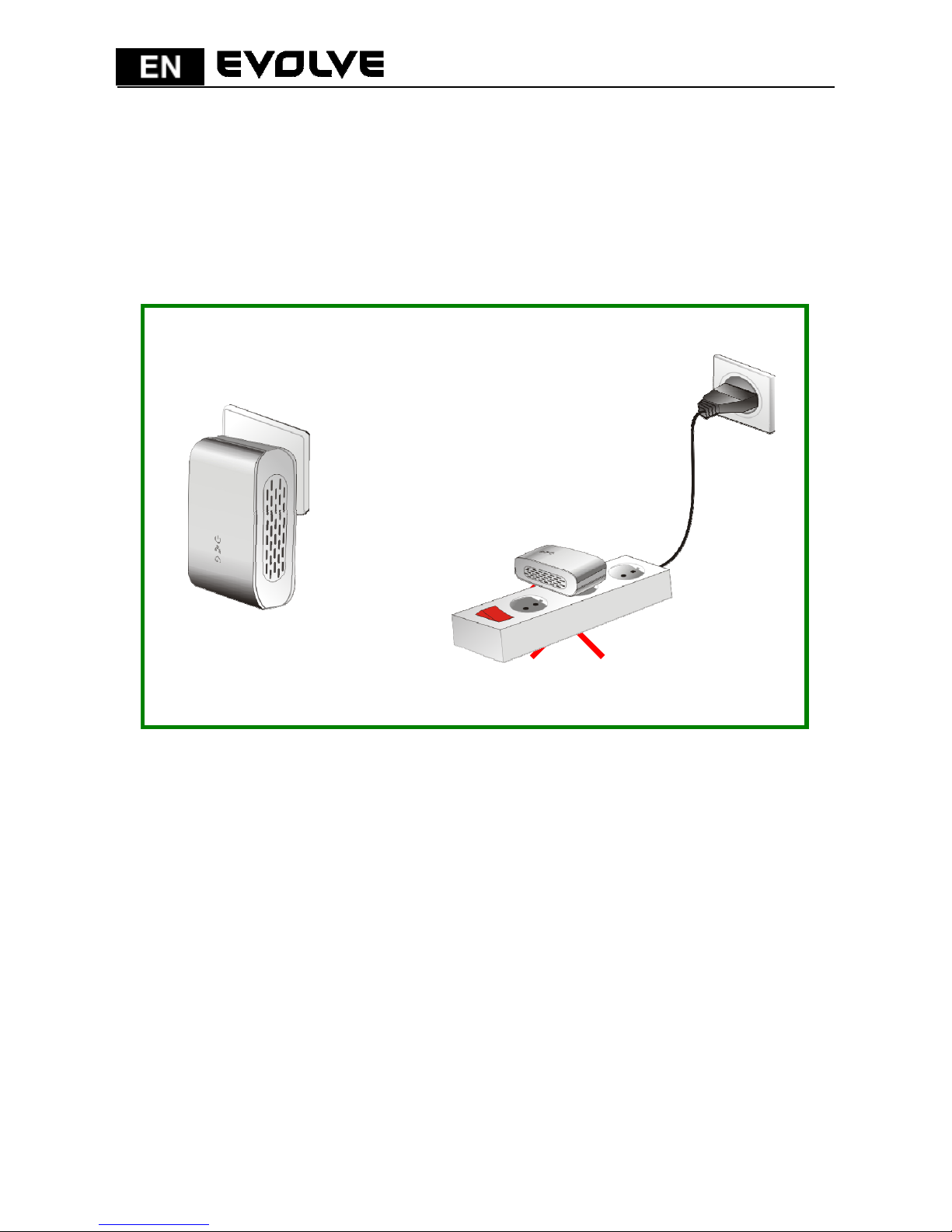
It is important to use the PLC product complying with the following "correct rules",
because it can significantly improve the transmission capacity of the network.
For the PLC device without a female socket, it is recommended to plug the device
directly into a wall socket instead of a power strip.
×
√
×
√
Figure 33: Connecting the PLC device without the female socket
Page 31
158
Appendix A Specifications
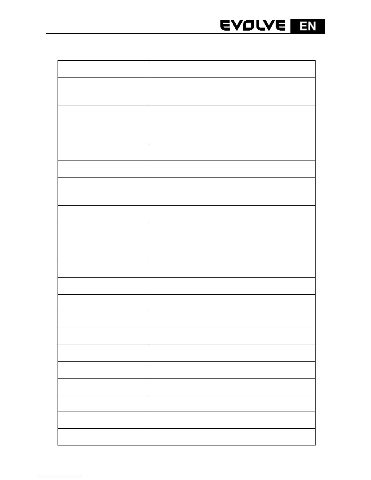
Chipset BCM60321
Protocol Compliant with HomePlugAV
Compliance with IEEE 1901 standard
System Support Windows 98SE, Windows 2000, Windows ME,
Windows XP 32/64 bit and Windows Vista 32/
64bit
PLC Rate 200 Mbps
Modulation Band 2MHz~28MHz
Modulation Schemes Support QAM 1024/256/64/16/8, QPSK, BPSK
and ROBO
Encryption 128 AES
LED Indicators Power :Power on and off
Ethernet: Ethernet link and activity
Data: PLC link and activity
Buttons Security/Reset
Consumption 3.25W
Operating Temperature 0ºC~40ºC
Storage Temperature -20ºC~70ºC
Operating Humidity 10%~90%, non-condensing
Storage Humidity 5%~95%, non-condensing
Power Supply 100 V~240 V AC, 50Hz/60Hz
Certifications CE, UL, FCC Part 15 Class B
Green Standard RoHS
Physical Characteristics L×W×H: 69 mm × 58 mm × 31 mm
Weight 80 g
Page 32
159
Appendix B Acronyms and Abbreviations
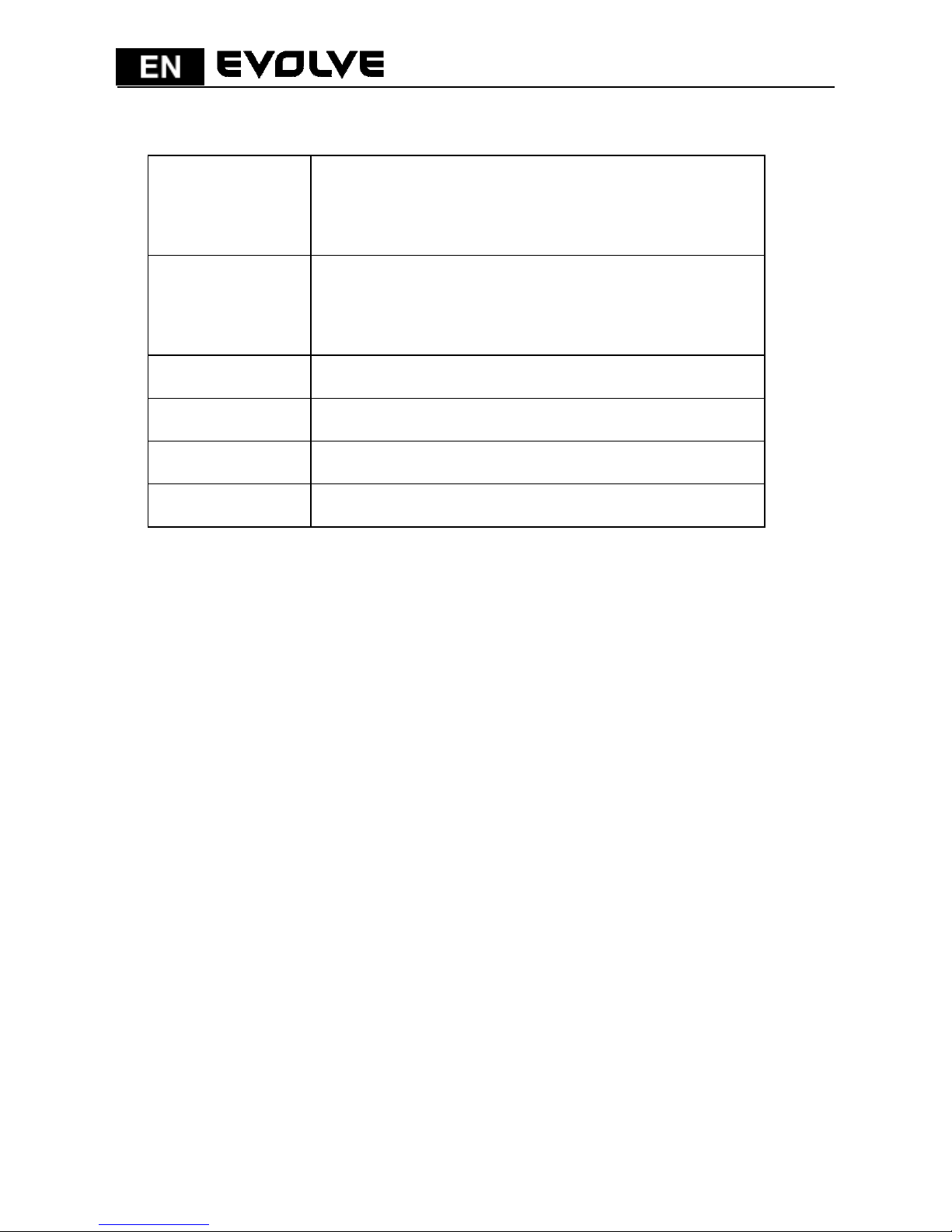
AVLN AV In-home Logical Network, the AVLAN is the set of
STAs that possess the same network Membership
key, every AVLN is managed by a single CCo
CCo Central Coordinator, the CCo is a superset of a STA
which includes terminal equipment identifiers and
global link identifiers
DEK Device Encryption Key
IGMP Internet Group Management Protocol
NPW Network Password
PLC Power Line Communication
 Loading...