

Evolve EVFE, Evolve EVS, Evolve EAG, Evolve EACG, Evolve EVBF Installation Instructions & Owner's Manual
...Page 1

Evolve Series®
Water Filters
For Models:
• EVFE
• EVS
• EAG
• EACG
• EVBF
• EVBF-AN
Page 2

TABLE OF CONTENTS
Preinstallation Instructions for Dealers . . . . . . . . . . . . . . . . . . . . . . . . . . . . . . . . . . 3
Bypass Valve . . . . . . . . . . . . . . . . . . . . . . . . . . . . . . . . . . . . . . . . . . . . . . . . . . . . . . . 4
Installation . . . . . . . . . . . . . . . . . . . . . . . . . . . . . . . . . . . . . . . . . . . . . . . . . . . . . . . . 5-7
Programming Procedures . . . . . . . . . . . . . . . . . . . . . . . . . . . . . . . . . . . . . . . . . . . .8-9
Start-up Instructions . . . . . . . . . . . . . . . . . . . . . . . . . . . . . . . . . . . . . . . . . . . . . . . . 10
Operating Displays and Maintenance . . . . . . . . . . . . . . . . . . . . . . . . . . . . . . . .11-12
Replacement Mineral Instructions for Acid Neutralizing Air Filters . . . . . . . . . . 13
Troubleshooting Guide . . . . . . . . . . . . . . . . . . . . . . . . . . . . . . . . . . . . . . . . . . . .14-18
Replacement Parts . . . . . . . . . . . . . . . . . . . . . . . . . . . . . . . . . . . . . . . . . . . . . . . .19-27
Specifications . . . . . . . . . . . . . . . . . . . . . . . . . . . . . . . . . . . . . . . . . . . . . . . . . . . . 28-29
Warranty . . . . . . . . . . . . . . . . . . . . . . . . . . . . . . . . . . . . . . . . . . . . . . . . . . . . . . . . . 30
Quick Reference Guide . . . . . . . . . . . . . . . . . . . . . . . . . . . . . . . . . . . . . . . . . . . . 31-32
YOUR WATER TEST
Hardness _____________________ gpg
Iron __________________________ ppm
pH ___________________________ number
*Nitrates ______________________ ppm
Manganese ___________________ ppm
Sulphur _______________________ yes/no
Total Dissolved Solids ___________
*Over 10 ppm may be harmful for human consumption.
Water conditioners do not remove nitrates or coliform bacteria,
this requires specialized equipment.
Your Evolve Series water filters are precision built, high quality products. These units will deliver filtered water for
many years to come, when installed and operated properly. Please study this manual carefully and understand the
cautions and notes before installing. This manual should be kept for future reference. If you have any questions
regarding your water conditioner, contact your local dealer or the manufacturer at the following:
1900 Prospect Court • Appleton, WI 54914
Phone: 920-739-9401 • Fax: 920-739-9406
Page 3

PREINSTALLATION INSTRUCTIONS FOR DEALERS:
The manufacturer has preset the water treatment unit’s sequence of cycles and cycle times.
The dealer should read this page and guide the installer regarding day override, time of regeneration, service alarm
and buzzer alarm settings before installation.
For the installer, the following must be used:
• Program Installer Settings ... Day Override (preset to 3 days), Time of Regeneration (preset to 12:00 a.m.;
see Operating Displays and Instructions for more details), Service Alarms (preset to “OFF”) and Buzzer Alarm
(preset to start at 6 a.m. and end at 10 p.m.)
• Read Normal Operating Displays
• Set Time of Day
• Read Power Loss & Error Display
For the homeowner, please read sections on Bypass Valve and Operating Displays and Maintenance.
During operation, the normal user display is time of day and gallons per minute.
Flow Rate, Vacation Mode, Capacity Remaining and Days to a Regeneration are optional displays but are not normally
used. (Vacation Mode is used only when there will be no water usage for an extended period of time. If activated, once
50 gallons of water is used, the unit will automatically regenerate that night and resume normal operation.) Each of these
can be viewed by pressing
pressed within 5 minutes, the display returns to a normal user display. Any changes made prior to the 5 minute time out
are incorporated. To quickly exit any Programming, Installer Settings, etc., press
the exit are incorporated.
NEXT to scroll through them. When stepping through any programming, if no buttons are
SET CLOCK. Any changes made prior to
If desired, two regenerations within 24 hours are possible with a return to the preset program.
To do a double regeneration:
1. Press the
2. Press and hold the REGEN button for three seconds until a regeneration begins.
Once the valve has completed the immediate regeneration, the valve will regenerate one more time at the preset.
REGEN button once. “REGEN TODAY” will flash on the display.
3
Page 4
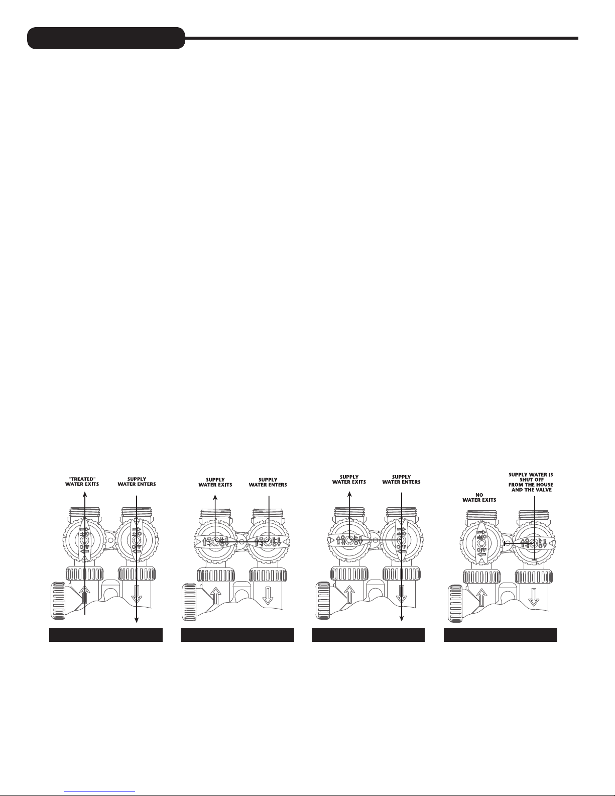
BYPASS VALVE:
The bypass valve is typically used to isolate the control valve from the plumbing system’s water pressure in order to perform control
valve repairs or maintenance. The 1” full flow bypass valve incorporates four positions, including a diagnostic position that allows
a service technician to have pressure to test a system while providing untreated bypass water to the building. Be sure to install
bypass valve onto main control valve, before beginning plumbing. Or, make provisions in the plumbing system for a bypass. The
bypass body and rotors are glass-filled Noryl
EPDM to help prevent valve seizing after long periods of non-use. Internal “O” Rings can easily be replaced if service is required.
The bypass consists of two interchangeable plug valves that are operated independently by red arrow shaped handles. The
handles identify the direction of flow. The plug valves enable the bypass valve to operate in four positions.
1. NORMAL OPERATION POSITION: The inlet and outlet handles point in the direction of flow indicated by the engraved
arrows on the control valve. Water flows through the control valve for normal operation of a water softener. During
the regeneration cycle this position provides regeneration water to the unit, while also providing untreated water to the
distribution system (Fig. 1).
2. BYPASS POSITION: The inlet and outlet handles point to the center of the bypass. The system is isolated from the water
pressure in the plumbing system. Untreated water is supplied to the building (Fig. 2).
3. DIAGNOSTIC POSITION: The inlet handle points toward the control valve and the outlet handle points to the center of
bypass valve. Untreated supply water is allowed to flow to the system and to the building, while not allowing water to exit
from the system to the building (Fig. 3). This allows the service technician to draw brine and perform other tests without the
test water going to the building.
NOTE: The system must be rinsed before returning the bypass valve to the normal position.
®
and the nuts and caps are glass-filled polypropylene. All seals are self-lubricating
4. SHUT OFF POSITION: The inlet handle points to the center of the bypass valve and the outlet handle points away from
the control valve. The water is shut off to the building. The water treatment system will depressurize upon opening a tap in
the building. A negative pressure in the building combined with the softener being in regeneration could cause a siphoning
of brine into the building. If water is available on the outlet side of the softener, it is an indication of water bypassing the
system (Fig. 4) (i.e. a plumbing cross-connection somewhere in the building).
NORMAL
OPERATION
POSITION
BYPASS POSITION
DIAGNOSTIC
POSITION
SHUT OFF
POSITION
FIGURE 1 FIGURE 3FIGURE 2 FIGURE 4
4
Page 5
INSTALLATION:
GENERAL INSTALLATION & SERVICE WARNINGS
The control valve, fittings and/or bypass are designed to accommodate minor plumbing misalignments. There is a small
amount of “give” to properly connect the piping, but the water softener is not designed to support the weight of the plumbing.
Do not use Vaseline, oils, other hydrocarbon lubricants or spray silicone anywhere. A silicone lubricant may be used on black
“O” Rings, but is not necessary. Avoid any type of lubricants, including silicone, on red or clear lip seals.
Do not use pipe dope or other sealants on threads. Teflon
brine line connection at the control valve, and on the threads for the drain line connection. Teflon® tape is not used on the nut
connections or caps because “O” Ring seals are used. The nuts and caps are designed to be unscrewed or tightened by hand
or with the special plastic Service Wrench, #CV3193-02. If necessary pliers can be used to unscrew the nut or cap. Do not
use a pipe wrench to tighten nuts or caps. Do not place screwdriver in slots on caps and/or tap with a hammer.
SITE REQUIREMENTS
• water pressure – 25-100 psi • current draw is 0.5 amperes
• water temperature – 33-100°F (0.5-37.7°C) • the plug-in transformer is for dry locations only
• electrical – 115/120V, 60Hz uninterrupted outlet • the tank should be on a firm level surface
®
tape must be used on the threads of the 1” NPT inlet and outlet, the
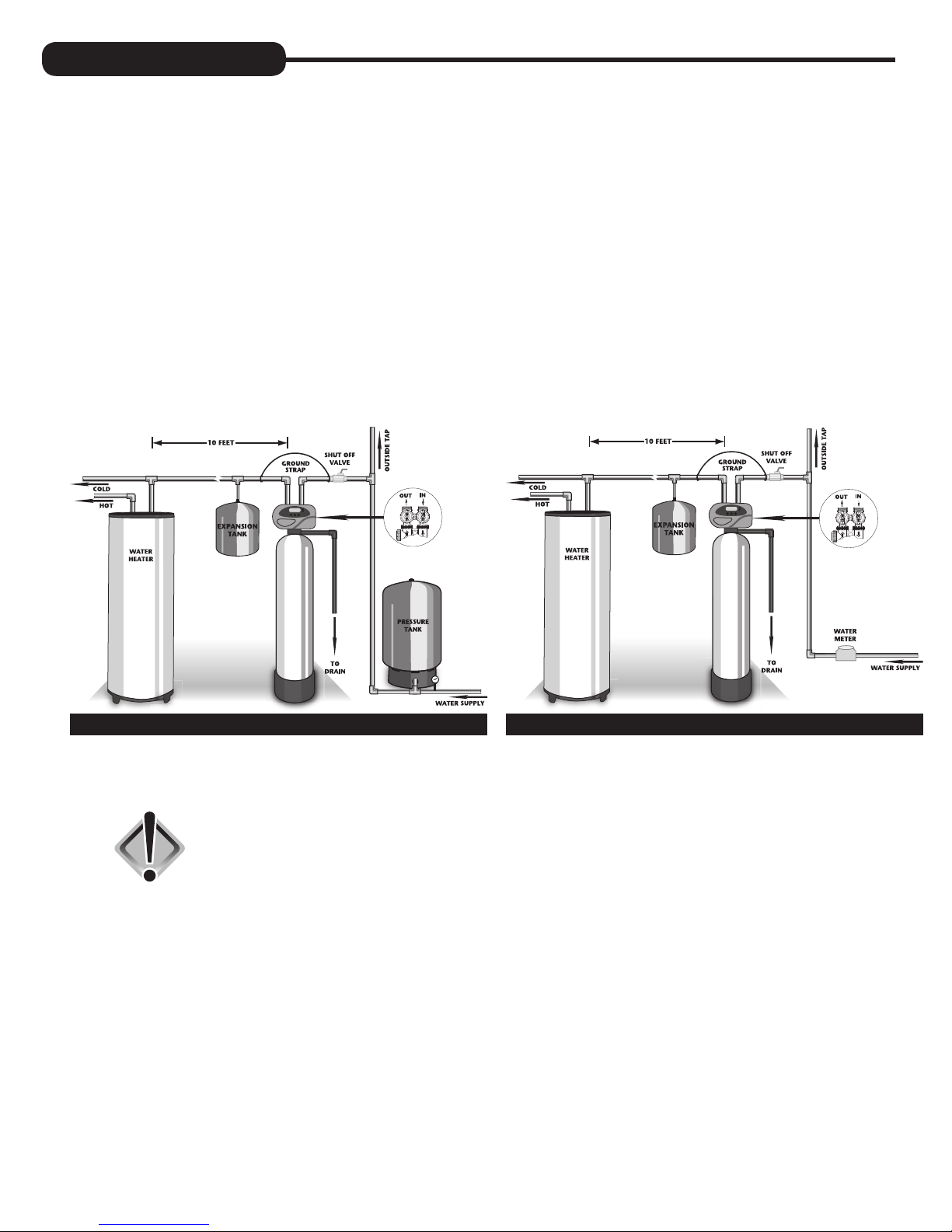
WELL WATER INSTALLATION MUNICIPAL INSTALLATION
1. The distance between the drain and the water conditioner should be as short as possible.
2. Do not install any water conditioner with less than 10 feet of piping between its outlet and the inlet of a water heater.
CAUTION: To protect the unit in the event of a hot water heater backup, the
manufacturer recommends the use of an expansion tank on the
outlet side of the unit.
3. Do not locate unit where it or its connections (including the drain and overflow lines) will ever be subjected to room
temperatures under 33°F.
4. Do not subject the tank to any vacuum, as this may cause an “implosion” and could result in leaking. If there is a possibility
a vacuum could occur, please make provision for a vacuum breaker in the installation.
5. INLET/OUTLET PLUMBING: Be sure to install Bypass Valve onto main control valve before beginning plumbing.
Make provisions to bypass outside hydrant and cold hard water lines at this time. Install an inlet shutoff valve and plumb
to the unit’s bypass valve inlet located at the right rear as you face the unit. There are a variety of installation fittings
available. They are listed under Installation Fitting Assemblies, page 26-27. When assembling the installation fitting
package (inlet and outlet), connect the fitting to the plumbing system first and then attach the nut, split ring and “O” Ring.
Heat from soldering or solvent cements may damage the nut, split ring or “O” Ring. Solder joints should be cool and
solvent cements should be set before installing the nut, split ring and “O” Ring. Avoid getting solder flux, primer, and
solvent cement on any part of the “O” Rings, split rings, bypass valve or control valve. If the building’s electrical system
is grounded to the plumbing, install a copper grounding strap from the inlet to the outlet pipe. Plumbing must be done in
accordance with all applicable local codes.
5
Page 6
When installing an air regenerating filter the customer may experience, under
certain conditions, small amounts of air (cloudy water) at the taps. This is
normal. On rare occasions, this may result in “shots of air” at a particular
(Air charge
models only)
fixture. By installing a loop or “U” on the outlet side of the unit, this will act as
an air trap and improve this situation.
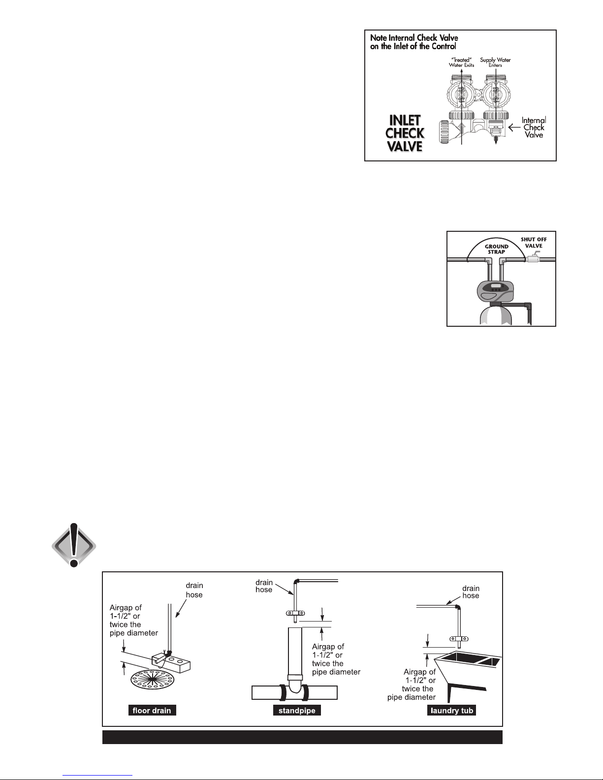
Located inside the inlet is an internal check valve (see diagram at right).
This check valve holds the air in the system, preventing its escape from the
tank. Plumbing codes may require the installation of a thermal expansion tank
on the outlet side of the system to prevent a water heater backup condition.
(See Installation Diagrams on page 5.)
Provisions should be made to bypass outside hydrants that are not to have filtered water. It is also advisable to install
hose bibs on the inlet and outside of the filter for future testing and service of the equipment. Where heavy sediment from
the well is observed, it is advisable to install a cartridge or bag-style filter immediately upstream from the filter. A nominal
micron rating of 50 to 100 is recommended. The purpose of this is to protect the control valve of any debris from the well.
If desired, a cartridge filter may be used after the system as a polishing filter.
6. INSTALLING GROUND: To maintain an electrical ground in metal plumbing of a home’s cold
water piping (such as a copper plumbing system), install a ground clamp or jumper wiring. If
replacing an existing filter, also replace the ground clamps/wire. If removing a filter, replace the
piping with the same type of piping as the original to assure plumbing integrity and grounding.
7. DRAIN LINE: First, be sure that the drain can handle the backwash rate of the system. Solder
joints near the valve must be done prior to connecting the drain line flow control fitting. Leave
at least 6” between the drain line flow control fitting and solder joints. Failure to do this could
cause interior damage to the flow control.
Backwash of an automatic filter can be directed into a septic tank in most cases, but because of the higher volume of
water discharged, care should be taken. The backwash discharge can be directed to a subsurface drainage system or
other safe location. Remember to follow all local codes.
When installing the drain line on any backwashing filter, especially Evolve filters that utilize air as the regenerant, hard
piping such as PVC, Schedule 80 Plastic or copper is recommended. Remove the drain line nut (if included) and discard.
A 3/4” NPT connection on the elbow is provided. During backwash, high volumes of water (more than a softener) and
air can be expelled. This release of air can cause a thrashing or movement of the drain line causing it to dislodge from the
drain, resulting in water damage. In order to prevent this, it is recommended to use other means of securing the drain line
to the floor, wall or ceiling to avoid this thrashing of piping. Our patent pending Backwash Air cycle greatly reduces the
chance of this occurring but should not be the only means of protection.
Where the drain line is elevated but empties into a drain below the level of the control valve, form a 7” loop at the
discharge end of the line so that the bottom of the loop is level with the drain connection on the control valve. This will
provide an adequate anti-siphon trap. Piping the drain line overhead <10 ft is normally not a problem. Be sure adequate
pressure is available (40-60 psi is recommended). Where the drain empties into an overhead sewer line, a sink-type trap
must be used. Run drain to its discharge point in accordance with plumbing codes. Pay special attention to codes for air
gaps and anti-siphon devices.
CAUTION: Never insert a drain line into a drain, sewer line, or trap. Always allow
an air gap between the drain line and the wastewater to prevent the
possibility of sewage being back-siphoned into the conditioner.
TYPICAL DRAIN LINE INSTALLATIONS
6
Page 7
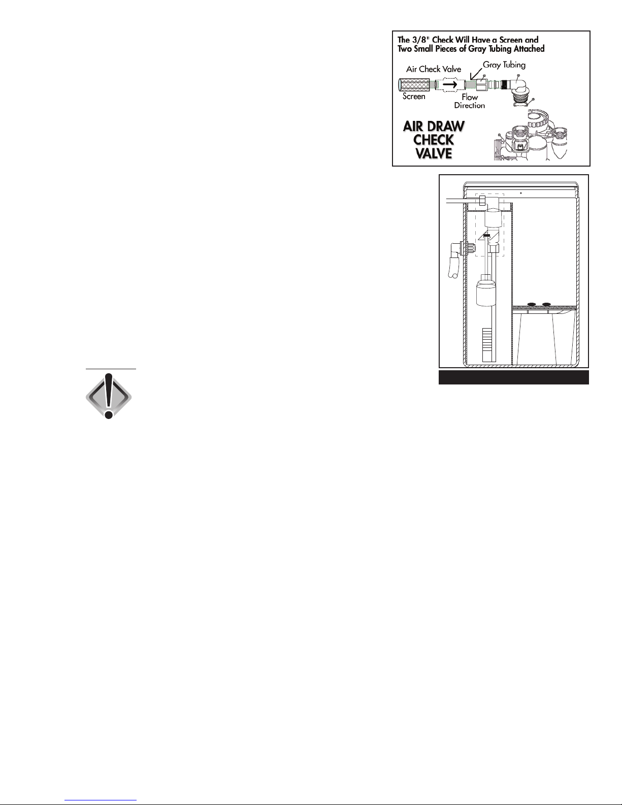
8. CHECK VALVE: On Evolve air filters, a 3/8” check valve is part of the
air draw assembly which includes tubing and a screen. Insert the tubing
into the elbow on the control valve (see diagram at right). As the
piston travels through various positions, ports are opened momentarily
(2-3 seconds) which may allow a small amount of water to discharge
through this assembly. The check valve prevents this flow of water.
NOTE: Under certain conditions (finished basement, utility room, etc.),
it may be advisable to run this air draw assembly to a drain.
9. DISINFECTION OF SYSTEM: In situations where additional disinfection is
needed, due to high levels of iron or sulfur bacteria, this may be accomplished
with a small chlorine feeder (see diagram at right). It can be used in
conjunction with air systems and is used to control bacterial growth within the
filter vessel itself. It is not used to control bacteria downstream of the filter nor for
disinfection of the water itself. Chlorine disinfection is not used with some medias
such as Birm. Please consult distributor or factory for more details.
This tank operates much the same way a brine tank does with a water softener.
A small amount of water is added to the tank just prior to regeneration, which
comes into contact with the chlorine pellets, dissolves them and is then drawn
into the filter to disinfect the system periodically and then safely rinsed away. We
recommend the use of pellets manufactured by Better Water Industries, available
through the manufacturer or your local distributor.
To Dealer:
CAUTION: On certain Evolve air models, the Backwash Air
cycle is not available when using the chlorine
feeder tank. Drain line must be of rigid materials and
affixed securely to floor, wall or ceiling. See Drain Line instructions.
CHLORINE FEEDER TANK
This tank has many intended uses. If chlorine is being used, add only two or
three pellets (two or three grams) of chlorine at a time. We recommend Better
Water Industries chlorine pellets. Do not overfill container. Use rubber gloves
when handling pellets. Always read safety precautions of chemical container
before adding to tank.
If chlorine is being used, never add or mix any chemical in chlorine tank other
than chlorine. Always read safety precautions on container before adding any
chemical to this tank. Only use in well ventilated area. Chlorine fumes can
be corrosive and harmful. Inhalation of chlorine gas can be deadly. Use drip
pan underneath tank in case of corrosion or leaking of tank. Always install
an overflow line to the chlorine tank and run to an appropriate drain. Do not
connect drain from filter to this tank. Drains should remain separate.
7
Page 8
PROGRAMMING PROCEDURES:
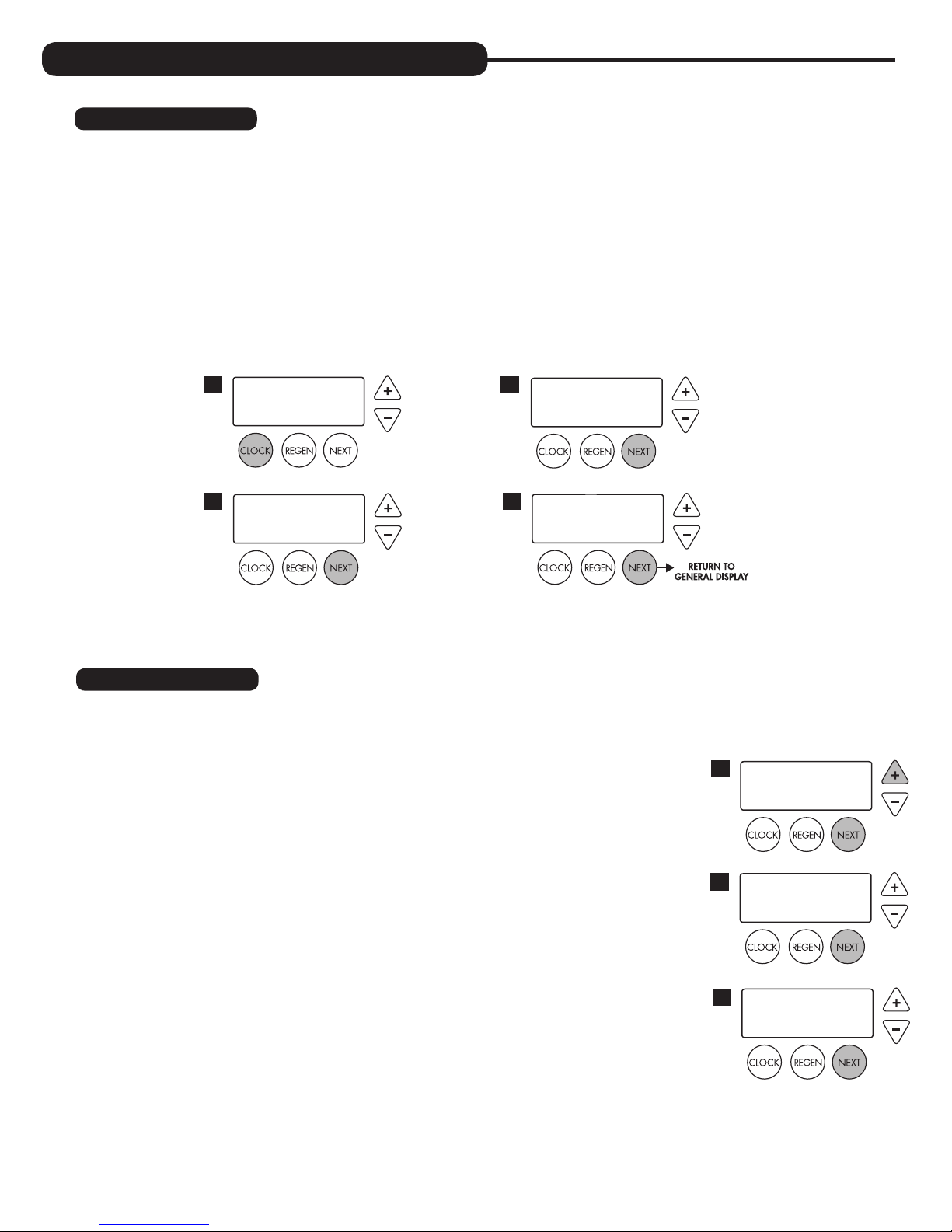
1. Set time of day:
Time of day should only need to be set after extended power outages or when daylight saving time begins or ends. If an
extended power outage occurs, the time of day will flash on and off indicating that the time should be reset.
STEP 1 – Press
STEP 2 – CURRENT TIME (HOUR): Set the hour of the day using + or — buttons. AM/PM toggles after 12.
STEP 3 – CURRENT TIME (MINUTES): Set the minutes using + or — buttons. If it is desired to back up to the
STEP 4 – CURRENT DAY: Set the day of the week using + or — buttons. Pressing
SET CLOCK.
Press
NEXT to go to step 3.
previous step press
return to the general operating display (page 9).
1
TIME MINUTES
3
SET
REGEN button once. Press NEXT to go to step 4.
2
4
2:10
AM
TIME HOUR
SET
CURRENT DAY
SET
2:00
MON
NEXT will exit SET CLOCK and
AM
2. Programming:
NOTE: The manufacturer has preset the unit so that the gallons between regenerations will be automatically calculated
after the hardness is entered.
STEP 1 – Press
STEP 2 – HARDNESS: Will not show because the manufacturer programmed the
NOTE: This display will show “–nA– (not available)” if “FILTER” is selected.
Press
Press
STEP 3 – DAYS BETWEEN REGENERATION (DAY OVERRIDE): The manufacturer
Set Day Override using + or — buttons (6 is recommended):
• set number of days between regeneration (1 to 28); or
• set to “OFF”
NEXT and + simultaneously for 3 seconds.
system to regenerate every 1,000 gallons or every 3 days as the default.
NEXT to go to step 3.
REGEN if you want to exit.
has factory set 6 DAYS as the default. This is the maximum number of days
between regenerations. If this is set to “OFF”, regeneration initiation is based
solely on gallons used. If any number is set (allowable range from 1 to 28), a
regeneration initiation will be called for on that day even if a sufficient number
of gallons were not used to call for a regeneration.
1
WATER HARDNESS
2
SET
DAYS BETWEEN REGEN
3
SET
-nA-
6
GR
8
Page 9

NOTE: This valve has the capability of regenerating up to six times in one day.
This can be observed by pressing the
CLOCK and + buttons simultaneously, then
using + or — buttons to toggle the correct number of regenerations per day
as desired (see example to right). Press
NEXT to set the times per day or select
“OFF” to return to Days Between Regen. These settings are typically used in
commercial settings.
Press
NEXT to go to step 4. Press REGEN to return to the previous step.
REGENS PER DAY
SET
Example: Indicates unit set
to regen 4 times in one day.
4 PER
STEP 4 – REGENERATION HOUR: The manufacturer has factory set 2:00 A.M. as
the default. This is the hour of day for regeneration and can be reset by using
+ or — buttons. “AM/PM” toggles after 12. The default time is 2:00 a.m.
(recommended for a normal household).
Press
NEXT to go to step 5. Press REGEN to return to the previous step.
STEP 5 – REGENERATION MINUTES: Set the minutes using + or — buttons. Press
NEXT to go to step 6. Press REGEN to return to previous step. To initiate an
immediate manual regeneration, press and hold the
REGEN button for three
seconds. The system will begin to regenerate immediately. The control may
be manually stepped through the regeneration cycles by pressing REGEN.
Press
NEXT to go to step 6. Press REGEN to return to the previous step.
STEP 6 – SERVICE ALARM GALLONS: The manufacturer has factory set “OFF”
as the default. This feature is used to signal service into the future. This
is typically set by the installing dealer to warn homeowner that service is
required after a preset number of gallons have been consumed. If the
feature is active, a specific gallon amount will appear.
Press
NEXT three times to advance past this screen.
STEP 7 – SERVICE ALARM TIME: The manufacturer has factory set “OFF” as the
default. This feature is used to signal service into the future. This is typically
set by the installing dealer to warn homeowner that service is required after a
period of time has passed. If the feature is active, a specific number of days
will appear.
Press
NEXT three times to advance past this screen.
REGEN TIME HOUR
4
SET
REGEN TIME MINUTES
5
SET
SERVICE ALARM
6
SET
SERVICE ALARM
7
SET
2:00
2:00
OFF
OFF
AM
AM
GAL
YR
STEP 8 – ALARM BUZZER: The manufacturer has factory set “ON” as the default. An
alarm will sound (at the indicated time) after a regeneration, if there is no salt
or if another error has occurred. Turn the alarm “OFF” or “ON” using the + or
— buttons. Press
NEXT.
NOTE: This feature allows you to program the time in which the alarm
buzzer will sound, permitting the installer to pick a time when the owner will
be home or awake to hear it.
Setting Alarm Buzzer Start Time: Press + or — button to select the correct
hour the buzzer is to start sounding. Be sure to also set AM or PM as necessary.
(Default is set to 6:00 a.m.) Press
NEXT.
Setting Alarm Buzzer End Time: Press + or — button to select the
correct hour the buzzer is to stop sounding in the day. Be sure to also set
AM or PM as necessary. (Default is set to 10:00 p.m.) Press
NEXT.
STEP 9 – DISPLAY BACKLIGHT: The manufacturer has factory set “ON” as the
default. Turn the light “OFF” or “ON” using the + or — buttons. “OFF”
will turn display backlight off after five minutes of keypad inactivity.
Press
NEXT to exit installer programming.
ALARM BUZZER START
8
SET
ALARM BUZZER END
SET
LIGHT NORMALLY
9
SET
10:00
6:00
ON
AM
PM
9
Page 10
START-UP INSTRUCTIONS:
FLUSHING OF SYSTEM:
To flush the system of any debris and air after installation is complete, please perform the following steps:
1. Rotate bypass handles to the bypass mode (see Fig. 2 of page 4).
2. Turn on inlet water and check for leaks in the newly installed plumbing.
3. Fully open a cold water faucet, preferable at a laundry sink or bathtub without an aerator.
4. Wait two to three minutes or until water runs clear, then turn water off and follow start-up instructions.
System regeneration sequence is in the following order. Some sequence differences may be noticed depending upon local
conditions. (If it is desired to change this sequence, please refer to the Dealer Manual or contact the manufacturer.)
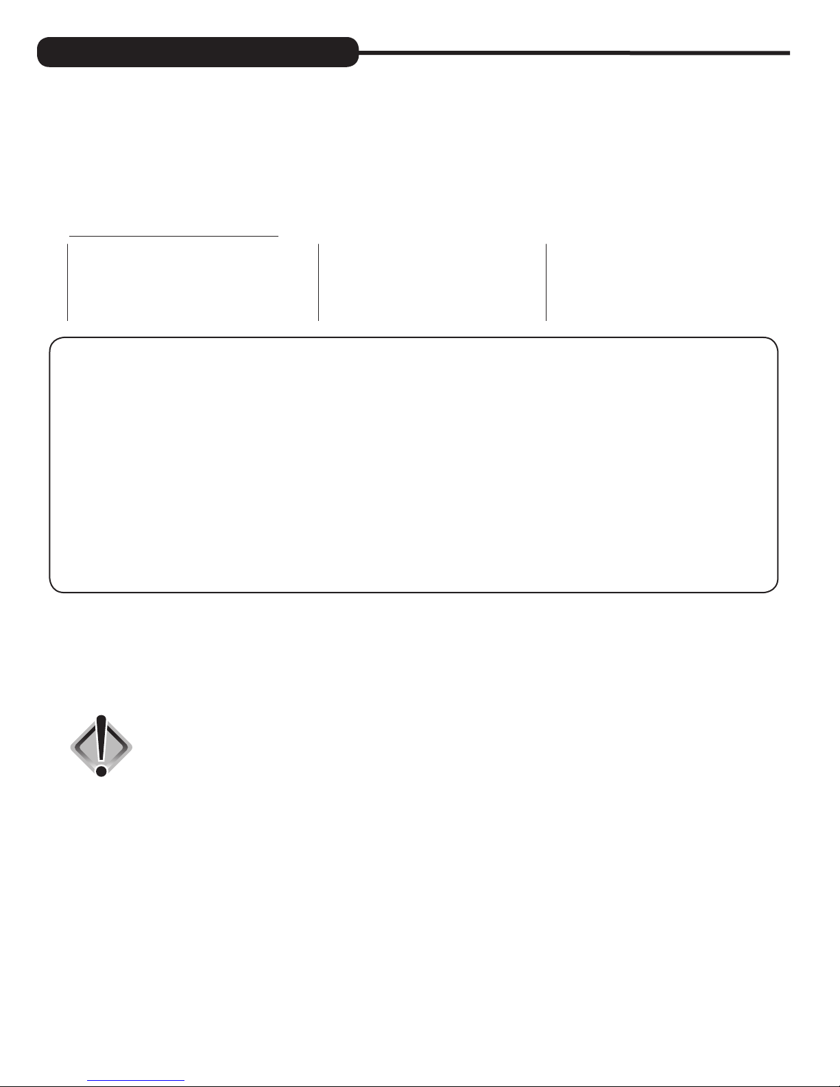
Sequencing for Various Filters:
Air Filters Backwashing Filters Acid Neutralizers
1. Backwash Air 1. Backwash 4. Rinse 1. Backwash 5. Filtering
2. Backwash 2. Rinse 5. Return to service 2. Filtering 6. Rapid Rinse
3. Regenerant Draw Down (Air draw) 3. Backwash 3. Rapid Rinse 7. Return to service
4. Return to service 4. Backwash
Inch Worm Feature: Evolve air units are programmed with the backwash air cycle feature (nicknamed “inch
worm”). This unique feature allows for small movements or “inching” of the piston towards the backwash cycle. As the
piston approaches this cycle, the backwash port opens slightly with each advancement, allowing air to escape to drain.
This cycle is ten very small mini steps of the piston which take place thirty seconds apart. Usually midway between the
ten positions, the air begins to be released very slowly to the drain in normal operating conditions.
When first starting up an air sulfur or air iron, it is advised to step through these positions and go to the normal backwash
cycle in order to fill the unit.
To advance in Backwash Air cycle:
1. Pushing the
NEXT button will advance to each of the ten mini steps within the backwash air cycle. While there are
usually eight steps to this cycle, the valve may make two or three movements for each step. Wait for these movements
to complete before pressing
2. Pushing and holding the
NEXT again.
REGEN button for three seconds while in the Backwash Air cycle will skip the remaining mini
steps and proceed to the next cycle of regeneration which is usually Backwash.
The system is now ready for filling with water and for testing.
1. Place the bypass valve into the bypass mode (Fig. 2 on page 4).
2. Press and hold the
REGEN button until the motor starts. Release button. Put the valve into “BACKWASH” position. (Please
see note above.) Unplug the transformer so that the valve will not cycle to the next position. Open the inlet handle of the
bypass valve very slightly allowing water to fill the tank slowly in order to expel air.
CAUTION: If water flows too rapidly, there will be a loss of media to the drain. Certain
medias such as carbon, or other dry media, should not be backwashed
immediately for extended periods of time. These medias need to “soak”
in the water for a 24-hour period prior to full backwash conditions.
Media is dry and filling with water too quickly in backwash will result in
media plugging the drain and valve assembly.
3. When the water is flowing steadily to the drain without the presence of air, slowly open the inlet valve. Restore power
and momentarily press the
REGEN button to advance the control to the “REGENERANT DRAW DOWN” position.
4. With the bypass still in the diagnostic mode (Fig. 3 on page 4), there should be a slow flow to the drain.
5. Press
REGEN button in sequence until display returns to “TIME.” Place bypass valve in the normal operating mode
(Fig. 1 on page 4) by opening the outlet bypass handle.
6. Go to laundry tub or bathtub faucet, preferable a faucet without an aerator, and turn on cold water. Let the water run.
Note the color of water coming from faucet. If discolored, let water run until clear. If severely discolored, place unit into
“BACKWASH” position (step 2) and run water to the system’s drain until clear.
Note: At no time should there by large particles of media noticed at faucet or laundry tub. If this is seen, immediately shut off
water and bypass system, as this could be an indication of a distributor failure. Contact manufacturer or distributor for assistance.
7. Place unit into regeneration again and allow to complete cycle. Upon completion, unit will be regenerated and will deliver
treated water.
10
Page 11
OPERATING DISPLAYS AND INSTRUCTIONS:
The air sulfur and air iron filter systems look and function much like any backwashing whole house filter; however,
unlike these conventional filters, they use air as a regenerant. This atmospheric air (containing oxygen) helps convert
iron or hydrogen sulfide into particles. These filters capture the particles of iron or hydrogen sulfide gas within the filter
media. Your dealer has recommended the proper media depending on your local water conditions. In some cases
where an acidic water condition (low pH) is present, the media may need to be periodically replenished if using this
filter to raise the pH to an acceptable level. Consult dealer for this service. The system is prefactory set to regenerate
every (3) three days at midnight. The frequency and start time of backwash/regeneration is adjustable to meet local
operating conditions and contaminant levels. Total backwash and recharge time is normally one half hour.
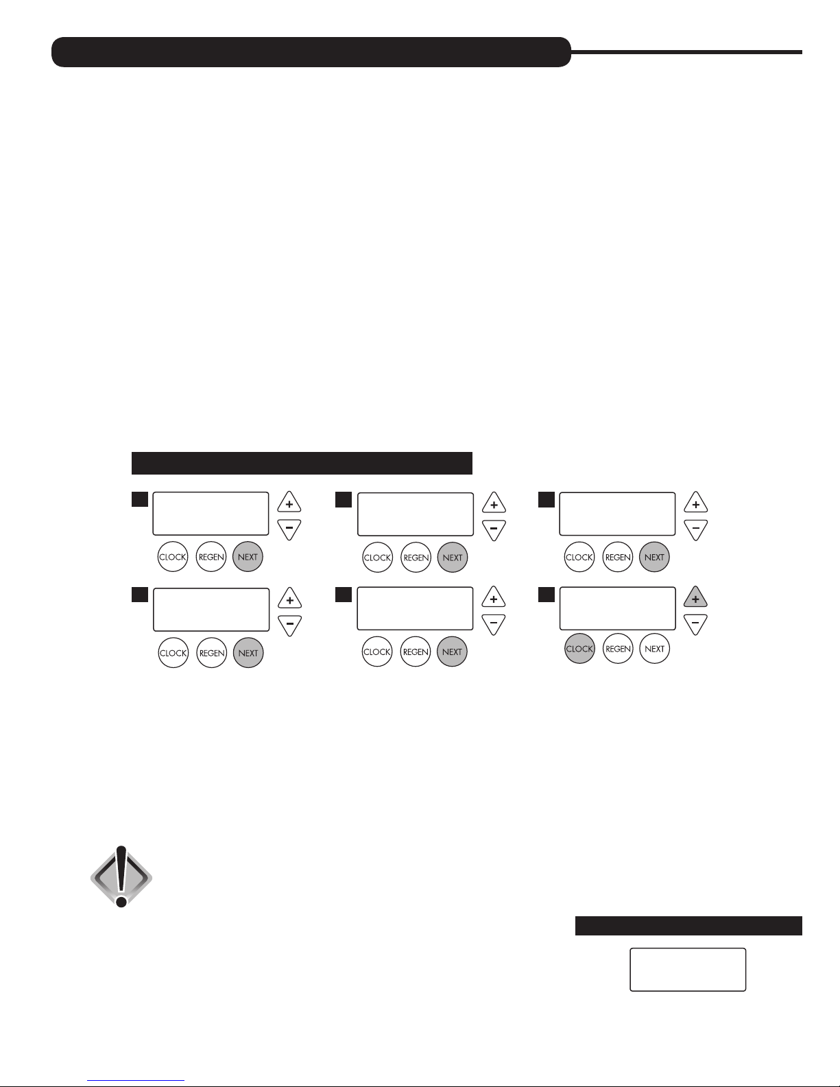
1. GENERAL OPERATION: When the system is operating, one of five displays may be shown and will alternate with the
installing dealer’s name and phone number for future service. Pressing
1. CURRENT TIME OF DAY and GPM
2. FLOW RATE which is the current treated water flow rate through the system in Gallons Per Minute
3. VACATION MODE allows the system to be “shut down” when there will be no water usage for an extended
period of time
4. CAPACITY REMAINING which is the gallons that will be treated before the system signals a regeneration cycle
5. DAYS TO A REGEN is the number of days left before the system goes through a regeneration cycle, based on
the days override value
6. DEALER NAME AND PHONE NUMBER is the dealer information to call when service is needed (this screen will
only appear if set by dealer)
NEXT will alternate between the displays.
The user can scroll between the displays as desired.
TIME OF DAY MON
1
GPM
CAPACITY REMAINING
4
GPM GAL
If the system has called for a regeneration that will occur at the preset time of regeneration, the words “REGEN
TODAY” will appear on the display.
If a water meter is installed, “GPM” flashes on the display when water is being treated, indicating gallons per
minute going through the system.
2. VACATION MODE: This feature may be used to “shut down” the system while on vacation. The manufacturer has
factory set “OFF” as the default. Turn feature “OFF” or “ON” using the + or — buttons. When turned “ON”, the
unit will not regenerate while there is no water usage. Once water usage is observed (minimum of 50 gallons), the
unit will automatically regenerate that night and resume normal operation.
1600
8
2:408
PM
FLOW RATE
2
DAYS TO A REGEN
5
GPM
8
8.0
3
GPM
ON VACATION
3
NO
PHONE NUMBER
6
DEALER NA
CAUTION: Depending on the severity of water conditions and the length of no water
usage, it may not be recommended to use this feature. Please contact
dealer or manufacturer for more information.
3. REGENERATION MODE: Typically a system is set to regenerate at a time of no
water usage. If there is a demand for water when the system is regenerating, untreated
water will be delivered. When the system begins to regenerate, the display will include
information about the step of the regeneration process and the time remaining for that
step to be completed. The system runs through the steps automatically and will reset
itself to provide treated water when the regeneration has been completed.
REGENERATION MODE
BACKWASH
8:22
11
Page 12
4. MANUAL REGENERATION: Sometimes there is a need to regenerate before the control
valve calls for it. This may be needed if a period of heavy water use is anticipated.
• To initiate a manual regeneration at the next preset regeneration time,
press and release
REGEN. The words “REGEN TODAY” will flash on the
MANUAL REGENERATION
display to indicate that the system will regenerate at the next regeneration
time (set in Programming, steps 4 and 5). If you pressed the
REGEN button
in error, pressing the button again will cancel the command.
• To initiate a manual regeneration immediately, press and hold the
REGEN
button for three seconds. The system will begin to regenerate immediately.
This command cannot be cancelled.
Once a manual regeneration is initiated, the unit will enter the first regeneration
cycle. Once the unit advances to its first position and subsequent positions
thereafter (see Start Up Instructions for regeneration sequence), the water filter will
deliver water, but it will be untreated.
REGEN TODAY and TIME OF DAY
will flash alternately if a regeneration
is expected tonight.
REGEN TODAY MON
GPM
2:408
PM
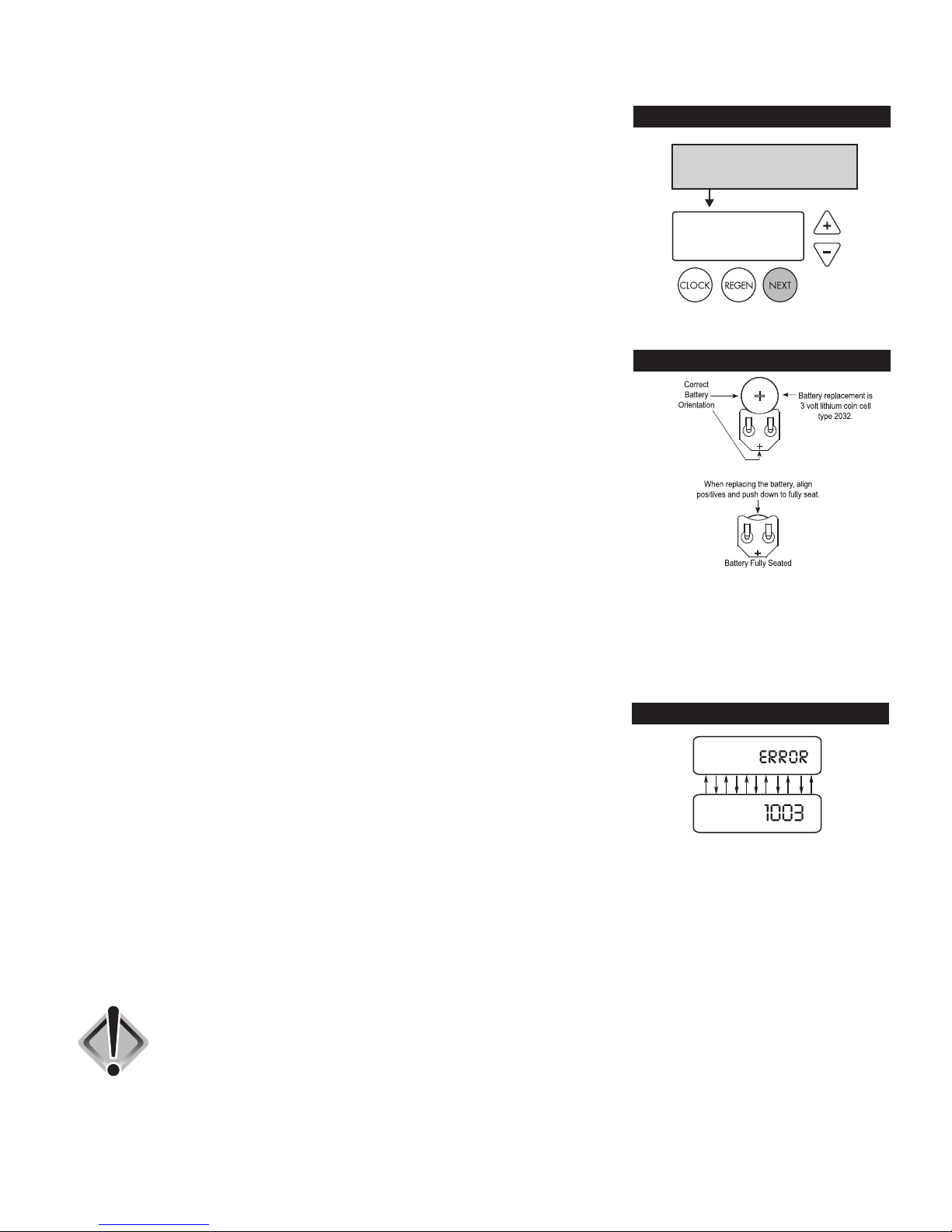
5. POWER LOSS AND BATTERY REPLACEMENT: The transformer comes
with a 15 foot power cord and is designed for use with the control valve; the
transformer should only be used in a dry location.
In the event of a power outage, the control valve will remember all settings and time of
day. If an extended power outage occurs, the control valve will keep time of day until
the battery is depleted. When the battery becomes depleted, the only item that needs
to be reset is the time of day and will be indicated by the time of day flashing or by a
blank screen. All other settings are permanently stored in the nonvolatile memory.
If a power loss occurs and the time of day flashes or a blank screen occurs, this
indicates that the battery is depleted. The time of day should be reset and the nonrechargeable battery should be replaced. The battery is a 3 Volt Lithium Coin Cell
type 2032 and is readily available at most stores. To access battery location, remove
front cover (see diagram on page 18 for battery location).
6. AUDIBLE ALARM: This control valve is equipped with an audible alarm and
visual alarm. This alarm is set by the installing dealer and is used to warn of
pending service, based on gallons or time.
To turn off alarm: If the audible alarm sounds, press any button on the
face of the control valve to turn off and call the dealer for service.
To reset: Both the gallon alarm setting and time alarm setting are reset
together by pushing and holding the + and – simultaneously for three seconds.
7. ERROR MESSAGE: If the word “ERROR” appears and flashes alternately with the
dealer name and phone number, record the ERROR number and your contact servicing
dealer promptly. This indicates that the control valve was not able to function properly.
BATTERY REPLACEMENT
ERROR
8. CHLORINE TANK AND MAINTENANCE: In severe cases where iron or
sulfate bacteria conditions exist, the dealer may have installed a chlorine tank with your system (see diagram, page 7).
These bacteria are harmless to human health, however they can produce a slime and occasionally an odor that can be a
nuisance. Filters equipped with a chlorine tank will periodically draw a chlorinated water solution into the filter tank killing
these unwanted bacteria within the filter itself. The chlorine is rinsed from the system during the regeneration process. More
specifically, a small amount of water will be added to the tank just prior to regeneration; this comes in contact with the
chlorine pellets, dissolves them, and is drawn into the filter to disinfect the system periodically.
We recommend the use of pellets manufactured by Better Water Industries, available through your dealer. Periodically check
storage tank and add two or three chlorine tablets (two or three grams) at a time.
CAUTION: This tank has many intended uses. If chlorine is being used, only add two or three
pellets (two or three grams) of chlorine at a time. We recommend Better Water
Industries chlorine pellets. Do not overfill container. Use rubber gloves when
handling pellets. Always read safety precautions of chemical container before
adding to tank. Keep out of reach of children!
If chlorine is being used, never add or mix any chemical in chlorine tank other than
chlorine. Only use in well ventilated area. Chlorine gas can be corrosive and harmful.
Inhalation of chlorine gas can be deadly. Use drip pan underneath tank in case of
corrosion or leaking of tank.
12
Page 13
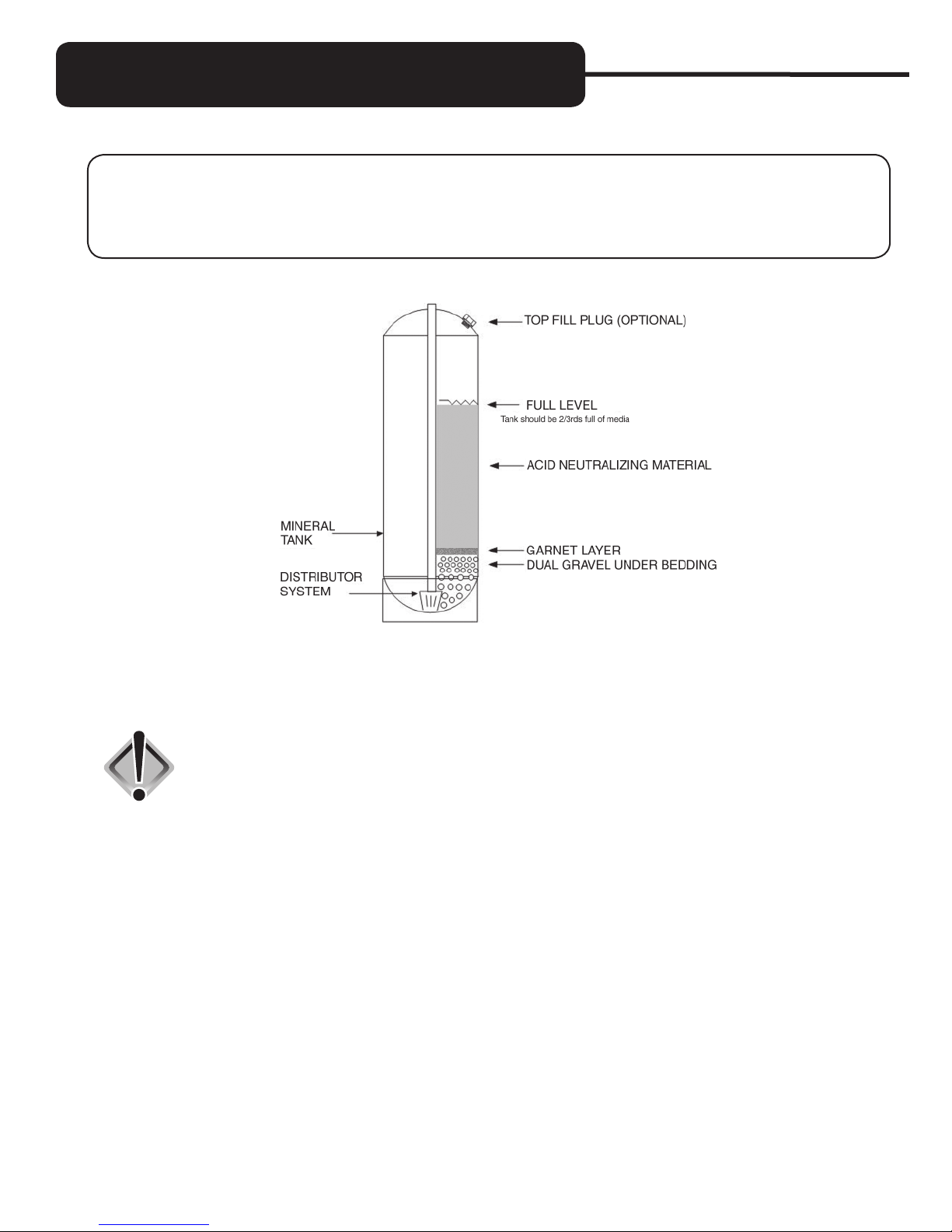
REPLACEMENT MINERAL INSTRUCTIONS
FOR ACID NEUTRALIZERS:
The EACG Iron Filter/Acid Neutralizer will remove iron and also raise the pH of mildly acidic water. The EVAN
Upflow Acid Neutralizer will raise the pH of acidic water. The raising of pH utilizes a sacrificial mineral that will need
replenishment every 6 to 12 months. Typically the media should not be below the halfway point in the tank. In order to
check the mineral height and before adding mineral to the system, please follow these instructions.
1. Check the media height by shining a flashlight through the tank to see the height of the mineral. If the level is not seen,
the top fill plug will have to be removed (if available) to measure the height. Proceed to step 2.
2. To remove top fill plug, turn off the source of the water and open a conditioned water tap to relieve the water
pressure on the system. Place unit into the bypass mode. Unscrew the top fill plug.
CAUTION: Never unscrew top fill plug unless pressure is fully released from system.
Serious injury and/or flooding can occur.
3. Siphon out some water from the tank through the dome hole. This will allow room when adding the media.
4. Add the appropriate amount of calcite (replacement media) through the dome hole. If needed, siphon out more
water as the media will displace the water inside the tank. Pay close attention to media level when filling. Do not
overfill. The additional media added should not be higher than two-thirds of the tank height when measuring
from the bottom (see diagram). Once the right height has been achieved, replace top fill plug. Grease “O” ring if
necessary using only silicone grease. Do not use petroleum based grease such as Vaseline. Tighten appropriately.
5. Leaving controller in the bypass position, turn on water source and refer to the start-up instructions of the controller
and complete the procedure.
6. Once start up is complete, please check the top fill plug for any leaking.
13
Page 14
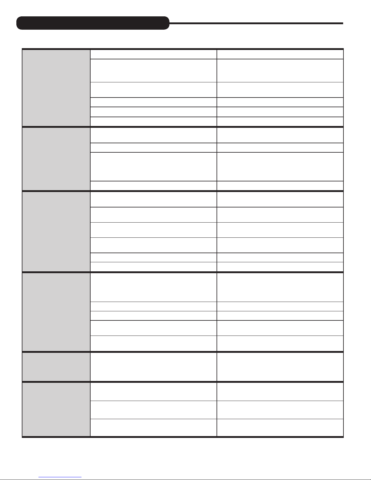
TROUBLESHOOTING GUIDE:
PROBLEM CAUSE CORRECTION
A. No power at electric outlet A. Repair outlet or use working outlet
1. No display on
PC board
B. Control valve power adapter not plugged into
outlet or power cord end not connected to PC
board connection
C. Improper power supply
D. Defective power adapter D. Replace power adapter
E. Defective PC board E. Replace PC board
F. Dead battery F. Replace battery
B. Plug power adapter into outlet or connect
power cord end to PC board connection
C. Verify proper voltage is being delivered to
PC board
2. PC board does not
display correct time
of day
3. Display does not
indicate that water is
flowing. Refer to user
instructions for how the
display indicates water
is flowing.
4. Control valve
regenerates at wrong
time of day
A. Power adapter plugged into electric outlet
controlled by light switch
B. Tripped breaker switch and/or tripped GFI B. Reset breaker switch and/or GFI switch
C. Power outage
D. Defective PC board D. Replace PC board
A. Bypass valve in bypass position
B. Meter is not connected to meter connection on
PC board
C. Restricted/stalled meter turbine
D. Meter wire not installed securely into three
pin connector
E. Defective meter E. Replace meter
F. Defective PC board F. Replace PC board
A. Power outage
B. Time of day not set correctly B. Reset to correct time of day
C. Time of regeneration set incorrectly C. Reset regeneration time
D. Control valve set at “on 0” (immediate
regeneration)
E. Control valve set at “NORMAL + on 0”
(delayed and/or immediate)
A. Use uninterrupted outlet
C. Reset time of day. If PC board has battery
back up present the battery may be depleted.
See front cover and drive assembly drawing
for instructions.
A. Turn bypass handles to place bypass in
service position
B. Connect meter to three pin connection labeled
METER on PC board
C. Remove meter and check for rotation or
foreign material
D. Verify meter cable wires are installed securely
into three pin connector labeled METER
A. Reset time of day. If PC board has battery
back up present the battery may be depleted.
See front cover and drive assembly drawing
for instructions.
D. Check programming setting and reset to
NORMAL (for a delayed regen time)
E. Check programming setting and reset to
NORMAL (for a delayed regen time)
5. Time of day flashes on
and off
6. Control valve does not
regenerate automatically
when the correct button(s)
is depressed and held.
For timeclock valves the
buttons are ▲ & ▼.
For all other valves the
button is REGEN.
A. Power outage
A. Broken drive gear or drive cap assembly A. Replace drive gear or drive cap assembly
B. Broken piston rod B. Replace piston rod
C. Defective PC board C. Defective PC board
A. Reset time of day. If PC board has battery
back up present the battery may be depleted.
See front cover and drive assembly drawing
for instructions.
14
Page 15
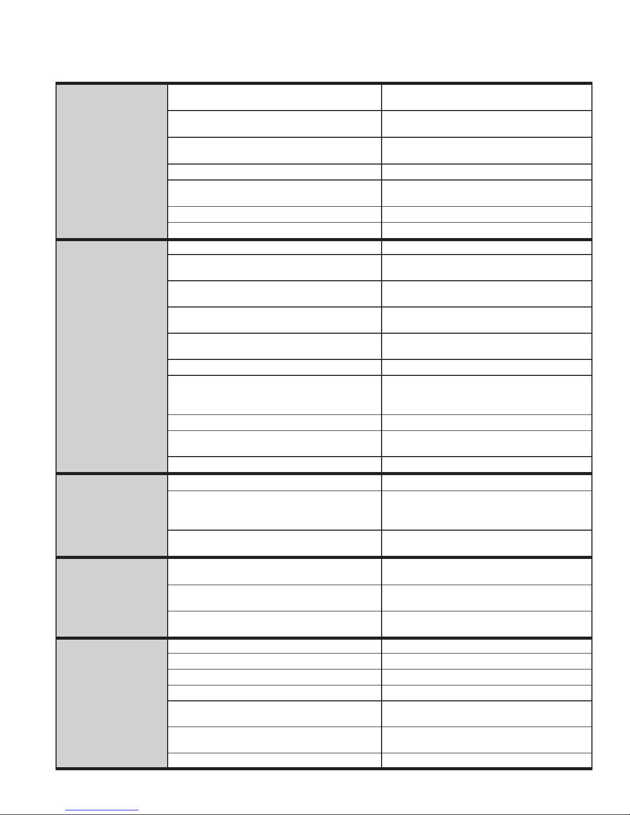
PROBLEM CAUSE CORRECTION
7. Control valve does not
regenerate automatically
but does when the
correct button(s) is
depressed and held.
For timeclock valves the
buttons are ▲ & ▼.
For all other valves the
button is REGEN.
8. Hard or untreated
water is being
delivered
A. Bypass valve in bypass position
B. Meter is not connected to meter connection on
PC board
C. Restricted/stalled meter turbine
D. Incorrect programming D. Check for programming error
E. Meter wire not installed securely into three
pin connector
F. Defective meter F. Replace meter
G. Defective PC board G. Replace PC board
A. Bypass valve is open or faulty A. Fully close bypass valve or replace
B. Media is exhausted due to high water usage
C. Meter not registering
D. Water quality fluctuation
E. No regenerant or low level of regenerant in
regenerant tank
F. Control fails to draw in regenerant F. Refer to Troubleshooting Guide number 12
G. Insufficient regenerant level in regenerant tank
H. Damaged seal/stack assembly H. Replace seal/stack assembly
I. Control valve body type and piston type
mix matched
J. Fouled media bed J. Replace media bed
A. Turn bypass handles to place bypass in
service position
B. Connect meter to three pin connection labeled
METER on PC board
C. Remove meter and check for rotation or
foreign material
E. Verify meter cable wires are installed securely
into three pin connector labeled METER
B. Check program settings or diagnostics for
abnormal water usage
C. Remove meter and check for rotation or
foreign material
D. Test water and adjust program
values accordingly
E. Add proper regenerant to tank
G. Check refill setting in programming. Check
refill flow control for restrictions or debris and
clean or replace
I. Verify proper control valve body type and
piston type match
9. Control valve uses too
much regenerant
10. Residual regenerant
being delivered to
service
11. Excessive water in
regenerant tank
A. Improper refill setting A. Check refill setting
B. Check program setting to make sure
B. Improper program settings
C. Control valve regenerates frequently
A. Low water pressure
B. Incorrect injector size
C. Restricted drain line
Improper program settings A. Check refill setting
A.
B. Plugged injector B. Remove injector and clean or replace
C. Drive cap assembly not tightened in properly C. Retighten the drive cap assembly
D. Damaged seal/stack assembly D. Replace seal/stack
E. Restricted or kinked drain line
F. Plugged backwash flow controller
G. Missing refill flow controller G. Replace refill flow controller
they are specific to the water quality and
application needs
C. Check for leaking fixtures that may be
exhausting capacity or system is undersized
A. Check incoming water pressure – water
pressure must remain at minimum of 25 psi
B. Replace injector with correct size for
the application
C. Check drain line for restrictions or debris
and clean
E. Check drain line for restrictions or debris and
or unkink drain line
F. Remove backwash flow controller and clean
or replace
15
Page 16
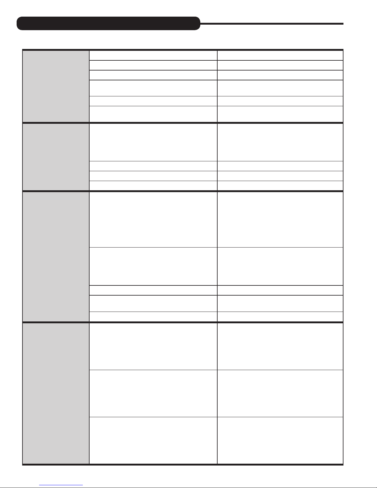
TROUBLESHOOTING GUIDE cont’d:
PROBLEM CAUSE CORRECTION
A. Injector is plugged A. Remove injector and clean or replace
B. Faulty regenerant piston B. Replace regenerant piston
C. Regenerant line connection leak C. Inspect regenerant line for air leak
12. Control valve fails to
draw in regenerant
13. Water running to
drain
14. E1, Err – 1001,
Err – 101 =
Control unable
to sense motor
movement
D. Drain line restriction or debris cause excess
back pressure
E. Drain line too long or too high E. Shorten length and or height
F. Low water pressure
A. Power outage during regeneration
B. Damaged seal/stack assembly B. Replace seal/stack assembly
C. Piston assembly failure C. Replace piston assembly
D. Drive cap assembly not tightened in properly D. Retighten the drive cap assembly
A. Motor not inserted fully to engage pinion,
motor wires broken or disconnected
B. PC board not properly snapped into drive bracket
D. Inspect drain line and clean to
correct restriction
F. Check incoming water pressure – water
pressure must remain at minimum of 25 psi
A. Upon power being restored control will finish
the remaining regeneration time. Reset time of
day. If PC board has battery back up present
the battery may be depleted. See front cover
and drive assembly drawing for instructions.
A. Disconnect power, make sure motor is fully
engaged, check for broken wires, make sure
two pin connector on motor is connected to the
two pin connection on the PC board labeled
MOTOR. Press NEXT and REGEN buttons for
3 seconds to resynchronize software with piston
position or disconnect power supply from PC
board for 5 seconds and then reconnect.
B. Properly snap PC board into drive bracket and
then Press NEXT and REGEN buttons for 3
seconds to resynchronize software with piston
position or disconnect power supply from PC
board for 5 seconds and then reconnect.
15. E2, Err – 1002, Err –
102 = Control valve
motor ran too short
and was unable to
find the next cycle
position and stalled
C. Missing reduction gears C. Replace missing gears
D. Board unable to read middle reduction gear
E. Defective Optical Encoder E. Replace PC board
A. Foreign material is lodged in control valve
B. Mechanical binding
C. Main drive gear too tight
D. Check foil on reduction gear; make sure no film
is covering foil on reduction gear
A. Open up control valve and pull out piston
assembly and seal/stack assembly for
inspection. Press NEXT and REGEN buttons for
3 seconds to resynchronize software with piston
position or disconnect power supply from PC
board for 5 seconds and then reconnect.
B. Check piston and seal/stack assembly, check
reduction gears, check drive bracket and main
drive gear interface. Press NEXT and REGEN
buttons for 3 seconds to resynchronize software
with piston position or disconnect power supply
from PC board for 5 seconds and then reconnect.
C. Loosen main drive gear. Press NEXT and
REGEN buttons for 3 seconds to resynchronize
software with piston position or disconnect
power supply from PC board for 5 seconds
and then reconnect.
16
Page 17
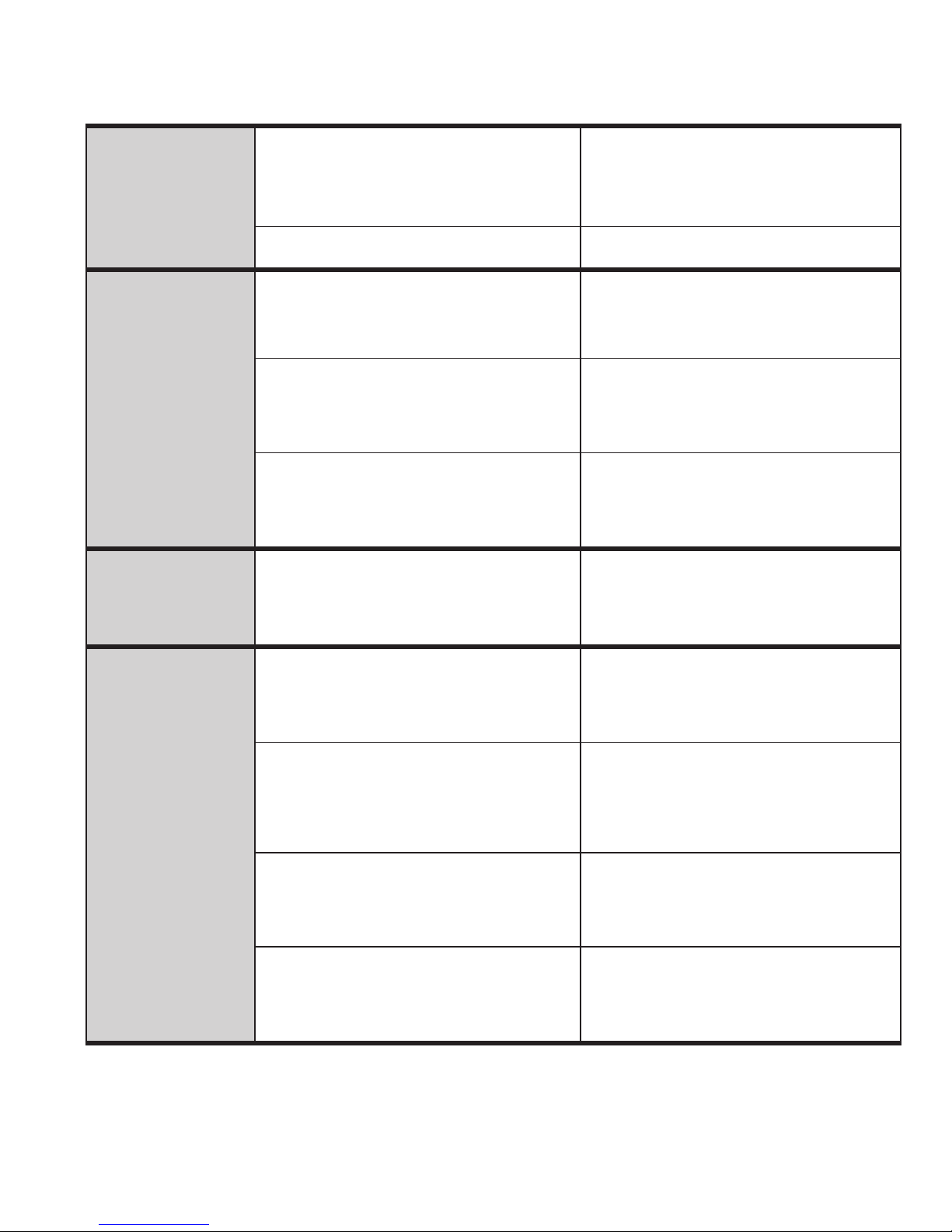
PROBLEM CAUSE CORRECTION
15. E2, Err – 1002, Err –
102 = Control valve
motor ran too short
and was unable to
find the next cycle
position and stalled
16. E3, Err – 1003, Err –
103 = Control valve
motor ran too long and
was unable to find the
next cycle position
17. E4, Err – 1004, Err –
104 = Control valve
motor ran too long
and timed out trying
to reach home position
D. Improper voltage being delivered to PC board
E. Valve type is programmed incorrectly
A. Motor failure during a regeneration
B. Foreign matter built up on piston and stack
assemblies creating friction and drag enough
to time out motor
C. Drive bracket not snapped in properly and out
enough that reduction gears and drive gear do
not interface
A. Drive bracket not snapped in properly and out
enough that reduction gears and drive gear do
not interface
D. Verify that proper voltage is being supplied.
Press NEXT and REGEN buttons for 3 seconds
to resynchronize software with piston position
or disconnect power supply from PC board for
5 seconds and then reconnect.
E. Verify valve body and program PC board
to match
A. Check motor connections then Press NEXT and
REGEN buttons for 3 seconds to resynchronize
software with piston position or disconnect
power supply from PC board for 5 seconds
and then reconnect.
B. Replace piston and stack assemblies. Press
NEXT and REGEN buttons for 3 seconds to
resynchronize software with piston position
or disconnect power supply from PC board
for 5 seconds and then reconnect.
C. Snap drive bracket in properly then Press
NEXT and REGEN buttons for 3 seconds to
resynchronize software with piston position
or disconnect power supply from PC board
for 5 seconds and then reconnect.
A. Snap drive bracket in properly then Press
NEXT and REGEN buttons for 3 seconds to
resynchronize software with piston position
or disconnect power supply from PC board
for 5 seconds and then reconnect.
18. Err -1006, Err – 106,
Err - 116 = MAV/
SEPS/ NHBP/ AUX
MAV valve motor ran
too long and unable
to find the proper
park position
Motorized Alternating
Valve = MAV
Separate Source = SEPS
No Hard Water Bypass
= NHBP
Auxiliary MAV = AUX
MAV
A. Control valve programmed for ALT A or B,
nHbP, SEPS, or AUX MAV with out having
a MAV or NHBP valve attached to operate
that function
B. MAV/NHBP motor wire not connected to
PC board
C. MAV/NHBP motor not fully engaged with
reduction gears
D. Foreign matter built up on piston and stack
assemblies creating friction and drag enough
to time out motor
A. Press NEXT and REGEN buttons for 3 seconds
to resynchronize software with piston position
or disconnect power supply from PC board for
5 seconds and then reconnect. Then reprogram
valve to proper setting
B. Connect MAV/NHBP motor to PC board two
pin connection labeled DRIVE. Press NEXT and
REGEN buttons for 3 seconds to resynchronize
software with piston position or disconnect
power supply from PC board for 5 seconds
and then reconnect.
C. Properly insert motor into casing, do not force
into casing Press NEXT and REGEN buttons for
3 seconds to resynchronize software with piston
position or disconnect power supply from PC
board for 5 seconds and then reconnect.
D. Replace piston and stack assemblies. Press
NEXT and REGEN buttons for 3 seconds to
resynchronize software with piston position
or disconnect power supply from PC board
for 5 seconds and then reconnect.
17
Page 18
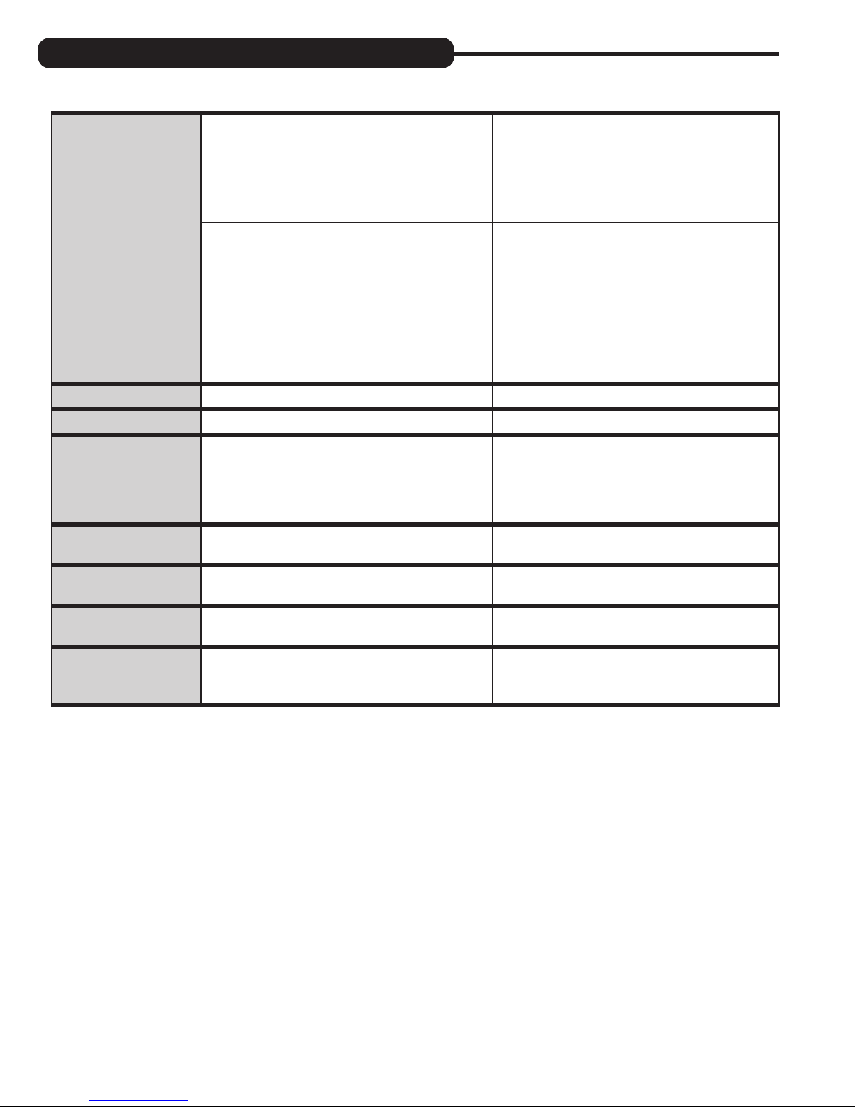
TROUBLESHOOTING GUIDE cont’d:
PROBLEM CAUSE CORRECTION
19. Err – 1007, Err – 107,
Err - 117 = MAV/
SEPS/NHBP/AUX
MAV valve motor
ran too short (stalled)
while looking for
proper park position
A. Foreign material is lodged in
MAV/NHBP valve
A. Open up MAV/NHBP valve and check piston
and seal/ stack assembly for foreign material.
Press NEXT and REGEN buttons for 3 seconds
to resynchronize software with piston position
or disconnect power supply from PC board for
5 seconds and then reconnect.
Motorized Alternating
Valve = MAV
Separate Source = SEPS
B. Mechanical binding
No Hard Water Bypass
= NHBP
Auxiliary MAV = AUX
MAV
20. Err – 109 A. Invalid motor state detected A. Replace PC board
21. Err – 201 A. Invalid regeneration cycle step detected A. Replace PC board
22. Err – 204 = Leak
detected
23. Err – 402 = Power
Down Memory
24. Err – 403 = Program
Memory
25. Err – 404 =
Diagnostic Memory
A. Occurs when dP input is active for “ALARM” and
the input is closed. The alarm buzzer will activate
and the screen will display the error.
A. Diagnostic memory failure during power down A. Replace PC board
A. Occurs when new software is flashed to a
PC board
A. Corrupt diagnostic display information is stored in
the memory
B. Check piston and seal/stack assembly, check
reduction gears, drive gear interface, and check
MAV/NHBP black drive pinion on
motor for being jammed into motor body.
Press NEXT and REGEN buttons for 3 seconds
to resynchronize software with piston position
or disconnect power supply from PC board for
5 seconds and then reconnect.
A. Check for low flow leak. Press NEXT and
REGEN buttons for 3 seconds to resynchronize
software with piston position or disconnect
power supply from PC Board for 5 seconds
and then reconnect to clear error.
A. Factory resets this error not seen in the field
A. Replace PC board
26. Err – 410 =
Configurator
Download
A. Occurs when downloading an invalid
configuration file
A. Not seen in the field
18
Page 19
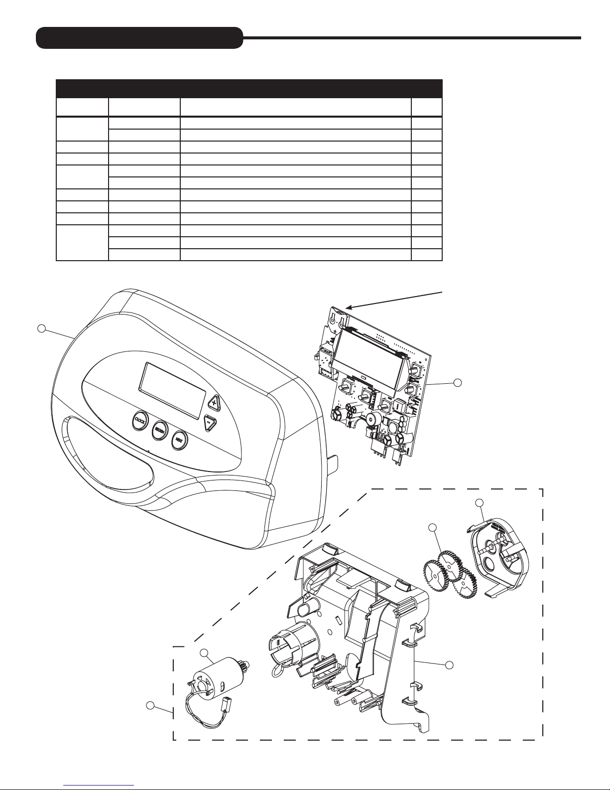
REPLACEMENT PARTS:
FRONT COVER AND DRIVE ASSEMBLY
Item No. Part No. Description Qty.
1
2 CV3107-1 Motor 1
3 CV3106-1 Drive bracket & spring clip 1
4
5 CV3110 Drive gear, 12 x 36 3
6 CV3109 Drive gear cover 1
7 CV3002CC Drive assembly, CC -
not shown
1
CV3367-01-A Black cover 1
CV3367-01-WR-A Gray cover 1
CV3502WE Evolve PC board (used on chlorine generator models) 1
CV4022WU Evolve PC board (standard) 1
CV3526 Transformer, 110V-15V, DC (used on chlorine generator models) 1
CV3186 Transformer, 110V-12V, AC (standard) 1
CV3684-WR-GLD Optional weather cover 1
NOTE: Battery Location
4
6
5
2
3
7
19
Page 20
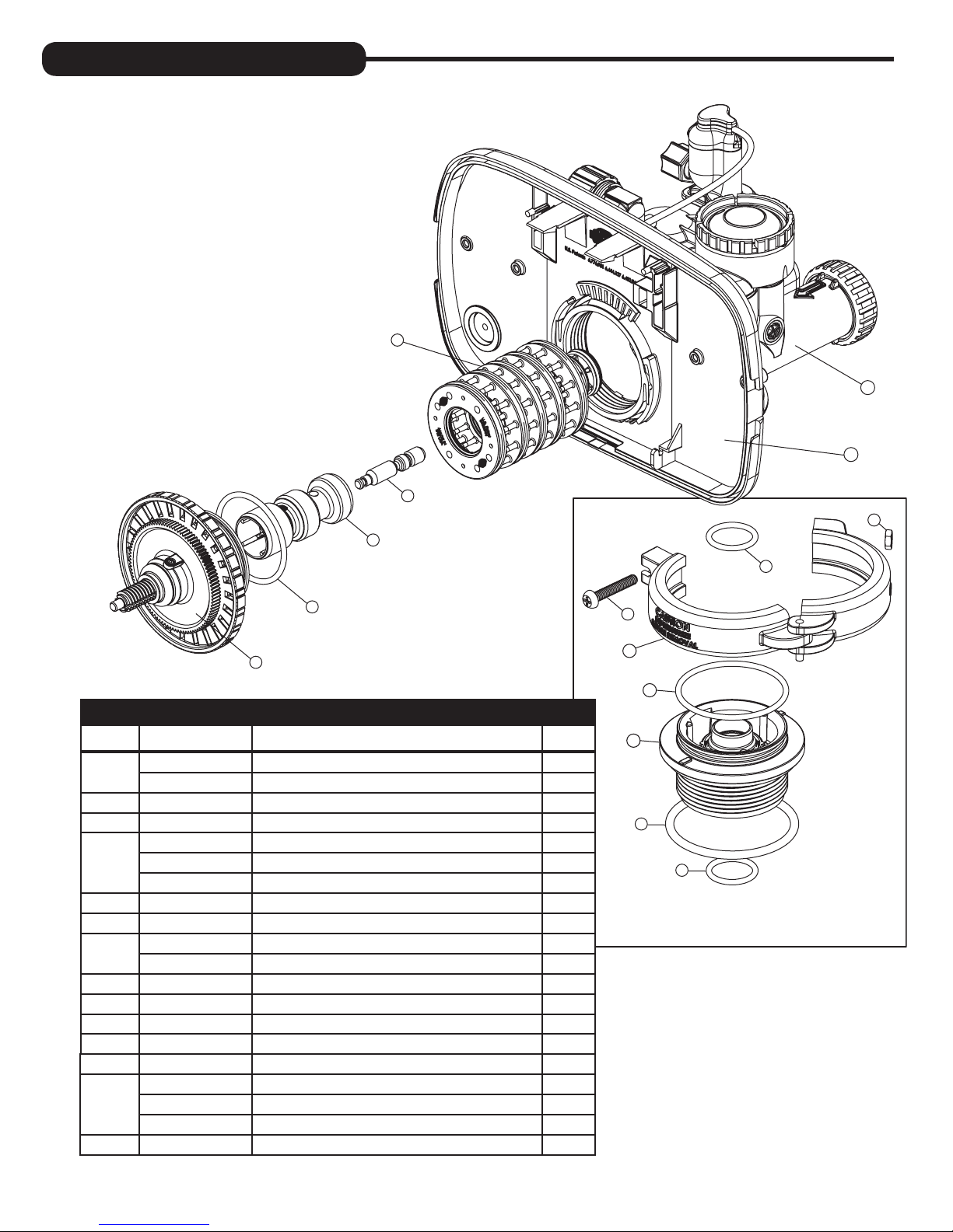
REPLACEMENT PARTS:
1
13
14
5
9
4
3
2
PISTON ASSEMBLY
Item No. Part No. Description Qty.
1
2 CV3004 Drive cap assembly 1
3 CV3135 O-ring 228 1
4
5 CV3174 Regenerant piston 1
6 CV3180 O-ring 337 1
7
8 CV3556 Screw, 1/4 - 20x1-1/2 18-8SS 1
9 CCI-00318337 Nut, 1/4-20 HEX 18-8SS 1
10 CV3016 QC2 clamp assembly (includes screw & nut) 1
11 CV3452 O-ring 230 1
12 CV3015 WS1 QC2 tank adapter assembly (includes O-rings) 1
13
14 CV3368 Drive backplate 1
CV3005 1” spacer stack assembly 1
CV3430 1.25” spacer stack assembly 1
CV3011 1” piston assembly downflow 1
CV3011-01 1” piston assembly upflow 1
CV3407 1.25” piston assembly downflow 1
CV3105 O-ring 215 1
CV3358 O-ring 219, 1.25” distributor
CV3001-04 1” body assembly downflow 1
CV3001UP 1” body assembly upflow 1
CV3020 1.25” body assembly downflow 1
7
8
10
11
12
6
7
NOTE: Not available on
1¼ " valve.
20
Page 21
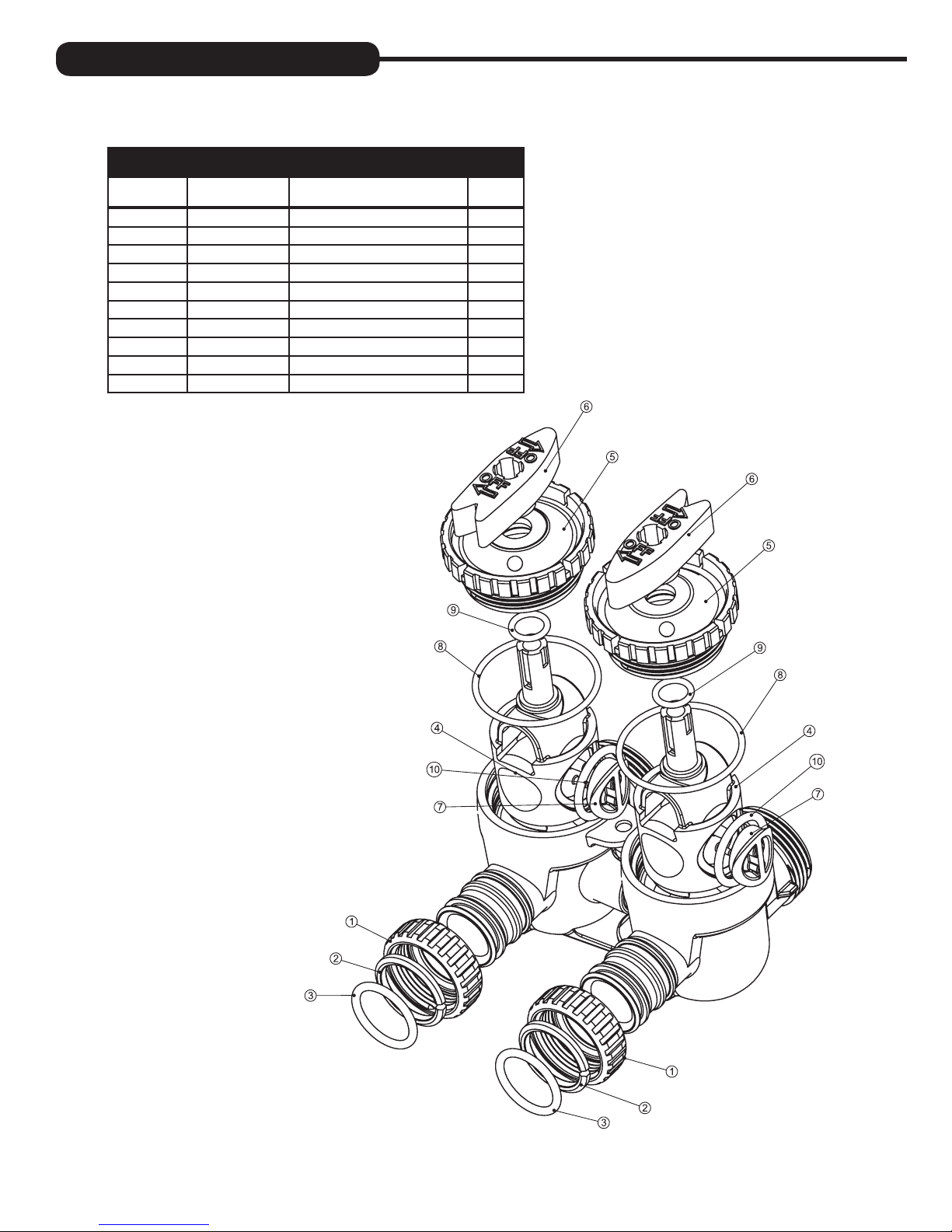
REPLACEMENT PARTS:
BYPASS VALVE
Item No. Part No. Description Qty.
1 CV3151 Nut, 1” quick connect 2
2 CV3150 Split ring 2
3 CV3105 O-ring 215 2
4 CV3145 Bypass rotor, 1” 2
5 CV3146 Bypass cap 2
6 CV3147 Bypass handle 2
7 CV3148 Bypass rotor seal retainer 2
8 CV3152 O-ring 135 2
9 CV3155 O-ring 112 2
10 CV3156 O-ring 214 2
21
Page 22
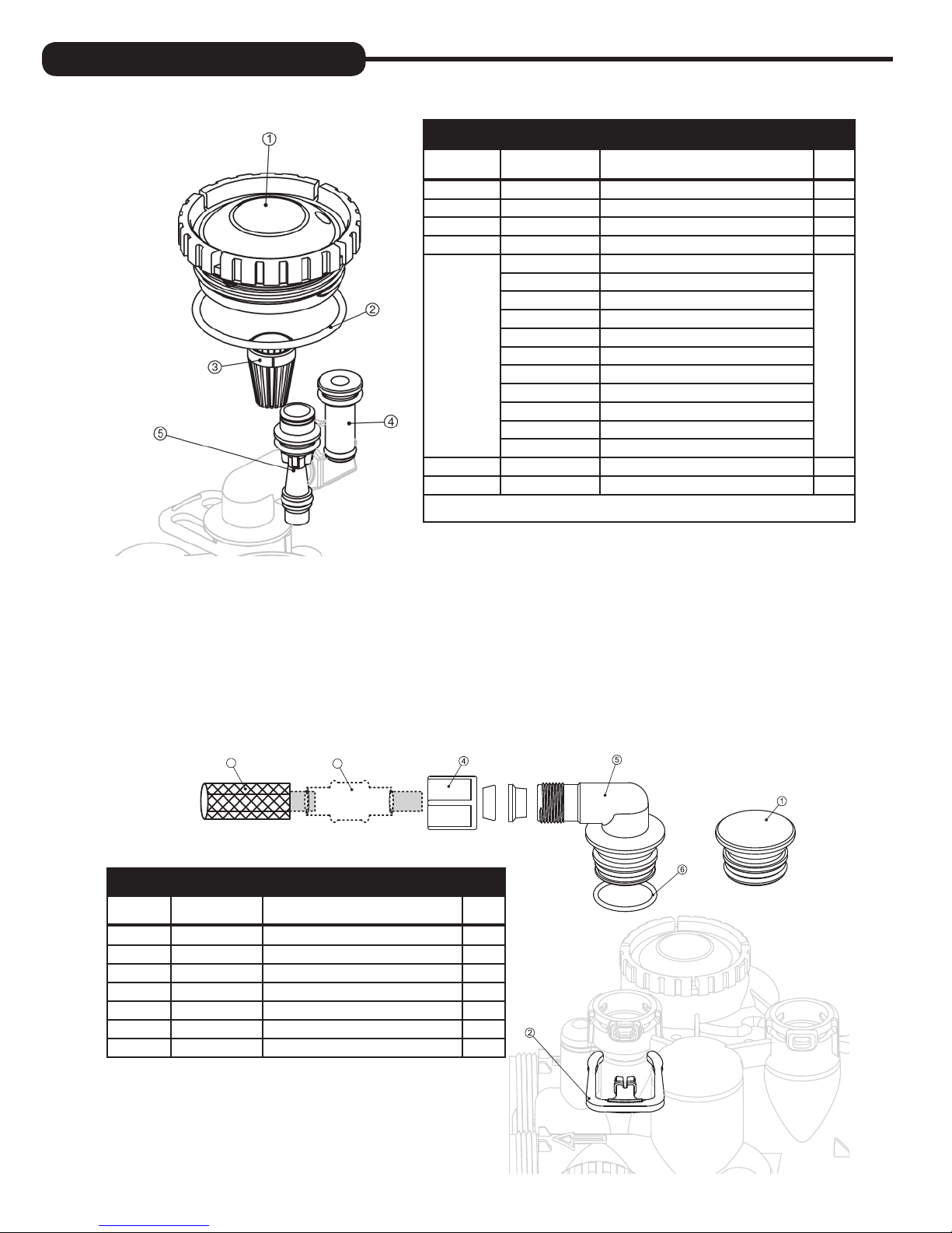
REPLACEMENT PARTS:
INJECTOR ASSEMBLIES
Item No. Part No. Description Qty.
1 CV3176 Injector cap 1
2 CV3152 O-ring 135 1
3 CV3177-01 Injector screen 1
4 CV3010-1Z Injector assembly plug 1
CV3010-1A A injector assembly,
CV3010-1B B injector assembly,
CV3010-1C C injector assembly, VIOLET
CV3010-1D D injector assembly, RED
CV3010-1E E injector assembly, WHITE
5
not shown CV3170 O-ring 011, lower *
not shown CV3171 O-ring 013, upper *
* The injector plug and the injector each use one lower and one upper o-ring
CV3010-1F F injector assembly, BLUE
CV3010-1G G injector assembly, YELLOW
CV3010-1H H injector assembly, GREEN
CV3010-1I I injector assembly, ORANGE
CV3010-1J J injector assembly, LIGHT BLUE
CV3010-1K K injector assembly, LIGHT GREEN
BLACK
BROWN
1
8
BRINE ELBOW ASSEMBLY
Item No. Part No. Description Qty.
1 CV3195-01 Refill port plug assembly 1
2
4
5
6
7 JG-38CV 3/8” John Guest check valve 1
8 H6061 Brine (MPU-14) strainer 1
CH4615 Elbow locking clip 1
CJCPG-6PBLK Nut, 3/8” 1
CH4613 Elbow cap, 3/8” 1
CV3163 O-ring 019 1
7
22
Page 23
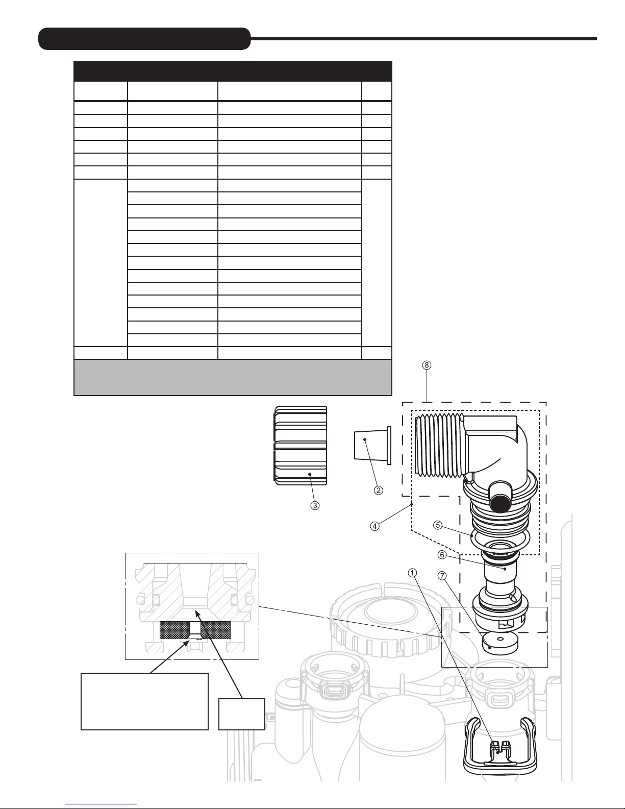
REPLACEMENT PARTS:
DRAIN LINE ASSEMBLY 3/4”
Item No. Part No. Description Qty.
1 CH4615 Elbow locking clip 1
2 CPKP10TS8-BULK Optional insert, 5/8” tube 1
3 CV3192 Optional nut, 3/4” drain elbow 1
4 CV3158-02 Drain elbow, 3/4” NPT with O-ring 1
5 CV3163 O-ring 019 1
6 CV3159-01 DLFC retainer assembly 1
CV3162-007 0.7 DLFC for 3/4” elbow
CV3162-010 1.0 DLFC for 3/4” elbow
CV3162-013 1.3 DLFC for 3/4” elbow
CV3162-017 1.7 DLFC for 3/4” elbow
CV3162-022 2.2 DLFC for 3/4” elbow
CV3162-027 2.7 DLFC for 3/4” elbow
7
8 CV3331 Drain elbow and retainer assembly
Items 2 and 3, nut and insert are only used with 1/2” I.D.
by 5/8” O.D. polytubing. For other piping material, the
3/4” NPT is used.
CV3162-032 3.2 DLFC for 3/4” elbow
CV3162-042 4.2 DLFC for 3/4” elbow
CV3162-053 5.3 DLFC for 3/4” elbow
CV3162-065 6.5 DLFC for 3/4” elbow
CV3162-075 7.5 DLFC for 3/4” elbow
CV3162-090 9.0 DLFC for 3/4” elbow
CV3162-100 10.0 DLFC for 3/4” elbow
1
3/4”
NPT
Proper DLFC orientation
directs water flow towards
the washer face with
rounded edge and lettering.
Water
Flow
23
Page 24
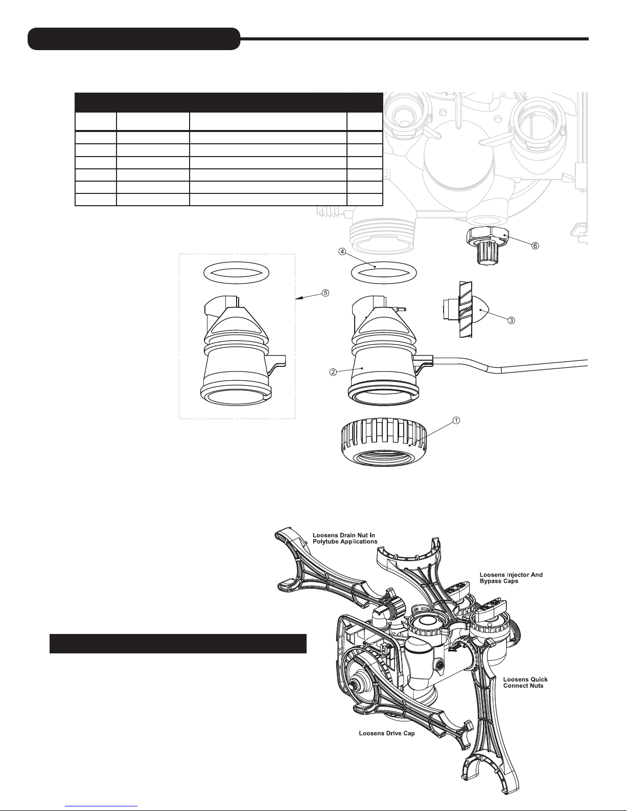
REPLACEMENT PARTS:
WATER METER & METER PLUG
Item No. Part No. Description Qty.
1 CV3151 Nut, 1” QC 1
2 CV3003 Meter assembly, includes items 3 & 4 1
3 CV3118-01 Turbine assembly 1
4 CV3105 O-ring 215 1
5 CV3003-01 Meter plug assembly 1
6 CV3013 Optional mixing valve 1
SERVICE WRENCH - CV3193-02
Although no tools are necessary to assemble
or disassemble the valve, the Service Wrench,
(shown in various positions on the valve) is
available to aid in assembly or disassembly.
24
Page 25
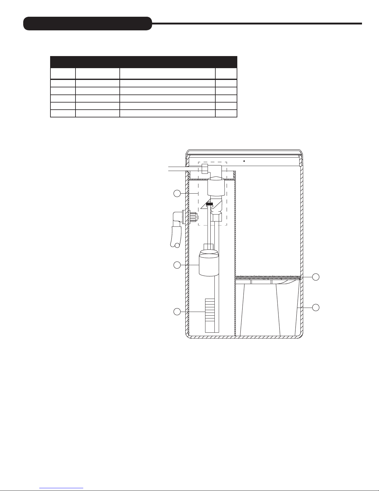
REPLACEMENT PARTS:
CHLORINE TANK ASSEMBLY
Item No. Part No. Description Qty.
1 CH4600-50 474 safety float valve 1
2 CH4640-32 474 float assembly 1
3 CH4500-48 474 air check 1
4 CN1043 10” pad for feeder 1
5 CH7001 Grid for feeder 1
1
2
4
3
5
25
Page 26
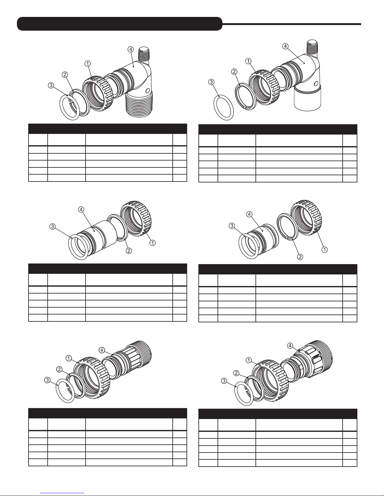
INSTALLATION FITTING ASSEMBLIES:
1” PVC MALE NPT ELBOW
Item
No.
1 CV3151 Nut, 1” quick connect 2
2 CV3150 Split ring 2
3 CV3105 O-ring 215 2
4 CV3149 Fitting 2
Part No. Description Qty.
CV3007 1” PVC male NPT elbow assembly 2
1” BRASS SWEAT
Item
No.
1 CV3151 Nut, 1” quick connect 2
2 CV3150 Split ring 2
3 CV3105 O-ring 215 2
4 CV3188 Fitting 2
Part No. Description Qty.
CV3007-02 1” brass sweat assembly 2
3/4” & 1” PVC SOLVENT ELBOW
Item
No.
1 CV3151 Nut, 1” quick connect 2
2 CV3150 Split ring 2
3 CV3105 O-ring 215 2
4 CV3189 Fitting 2
Part No. Description Qty.
CV3007-01 3/4” & 1” PVC solvent elbow assembly 2
3/4” BRASS SWEAT
Item
No.
1 CV3151 Nut, 1” quick connect 2
2 CV3150 Split ring 2
3 CV3105 O-ring 215 2
4 CV3188-01 Fitting 2
Part No. Description Qty.
CV3007-03 3/4” brass sweat assembly 2
1” PLASTIC MALE NPT
Item
No.
1 CV3151 Nut, 1” quick connect 2
2 CV3150 Split ring 2
3 CV3105 O-ring 215 2
4 CV3164 Fitting 2
Part No. Description Qty.
CV3007-04 1” plastic male NPT assembly 2
26
1-1/4” PLASTIC MALE
Item
No.
1 CV3151 Nut, 1” quick connect 2
2 CV3150 Split ring 2
3 CV3105 O-ring 215 2
4 CV3317 Fitting 2
Part No. Description Qty.
CV3007-05 1-1/4” plastic male assembly 2
Page 27
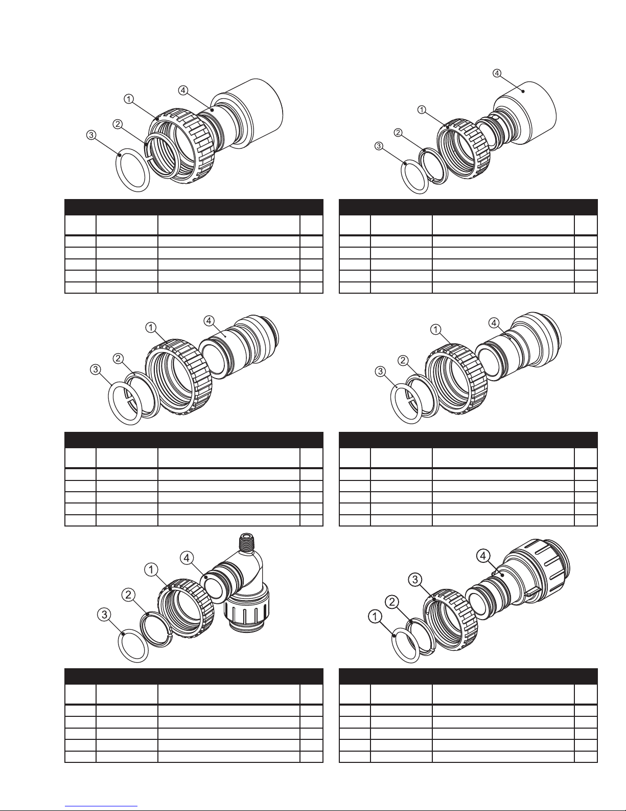
1-1/4” & 1-1/2” BRASS SWEAT
Item
No.
1 CV3151 Nut, 1” quick connect 2
2 CV3150 Split ring 2
3 CV3105 O-ring 215 2
4 CV3375 Fitting 2
Part No. Description Qty.
CV3007-09 1-1/4 & 1-1/2” brass sweat assembly 2
1-1/4” & 1-1/2” PVC SOLVENT
Item
No.
1 CV3151 Nut, 1” quick connect 2
2 CV3150 Split ring 2
3 CV3105 O-ring 215 2
4 CV3352 Fitting 2
Part No. Description Qty.
CV3007-07 1-1/4” & 1-1/2” PVC solvent assembly 2
3/4” BRASS SHARK BITE
Item
No.
1 CV3151 Nut, 1” quick connect 2
2 CV3150 Split ring 2
3 CV3105 O-ring 215 2
4 CV3628 Fitting 2
Part No. Description Qty.
CV3007-12 3/4” brass Shark Bite assembly 2
3/4” JOHN GUEST ELBOW
Item
No.
1 CV3151 Nut, 1” quick connect 2
2 CV3150 Split ring 2
3 CV3105 O-ring 215 2
4 CV3790 Fitting 2
Part No. Description Qty.
CV3007-15 3/4” John Guest elbow assembly 2
1” BRASS SHARK BITE
Item
No.
1 CV3151 Nut, 1” quick connect 2
2 CV3150 Split ring 2
3 CV3105 O-ring 215 2
4 CV3629 Fitting 2
Part No. Description Qty.
CV3007-13 1” brass Shark Bite assembly 2
1” JOHN GUEST
Item
No.
1 CV3151 Nut, 1” quick connect 2
2 CV3150 Split ring 2
3 CV3105 O-ring 215 2
4 CV4045 Fitting 2
Part No. Description Qty.
CV3007-17 1” John Guest elbow assembly 2
27
Page 28
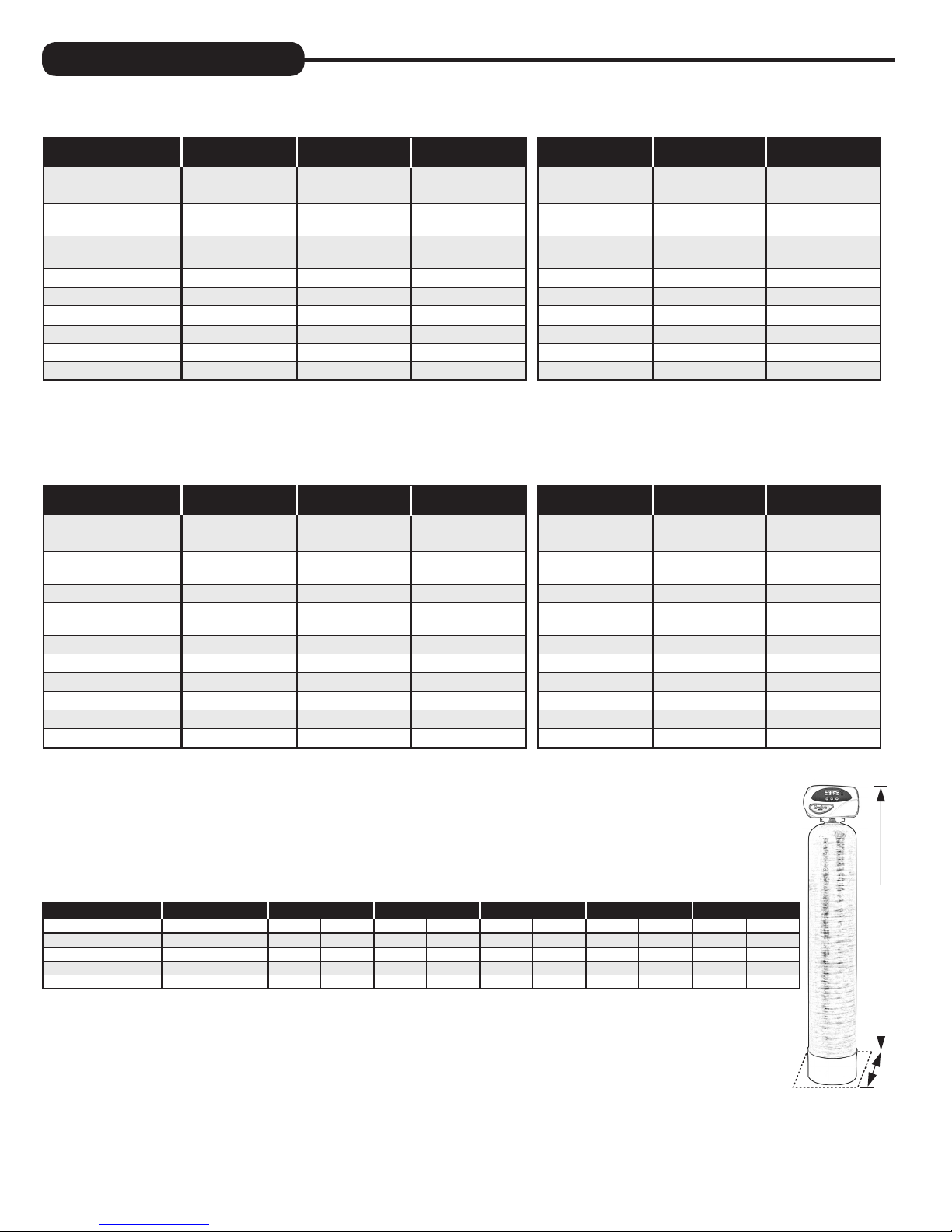
SPECIFICATIONS:
SULFUR AND IRON AIR FILTERS
MODEL NUMBER EVS-1054 EVS-1248 EVS-1354 EVFE-1054 EVFE-1248 EVFE-1354
Mineral Type Catalytic Carbon Catalytic Carbon Catalytic Carbon Birm Birm Birm
Amount (Cu Ft) 1.0 1.5 2.0 1.0 1.5 2.0
Gravel Amount/Size (No. 1) 14 lb 1/4 x 1/8 21 lb 1/4 x 1/8 21 lb 1/4 x 1/8 14 lb 1/4 x 1/8 21 lb 1/4 x 1/8 21 lb 1/4 x 1/8
Gravel Amount/Size (No. 2) 7 lb #20 7 lb #20 7 lb #20 7 lb #20 7 lb #20 7 lb #20
Continuous Flow (GPM) 5.0 6.0 7.0 5.0 6.0 7.0
1
Peak Flow (GPM) 20.0 22.0 22.0 18.0 19.0 19.0
Backwash Flow (GPM) 5.3 7.5 9.0 5.3 9.0 10.0
2
Iron Removal 1.0 1.0 1.0 5.0 5.0 5.0
3
Hydrogen Sulfide Removal 5.0 5.0 5.0 1.0 1.0 1.0
pH Range Greater than 7.0 Greater than 7.0 Greater than 7.0 Greater than 7.0 Greater than 7.0 Greater than 7.0
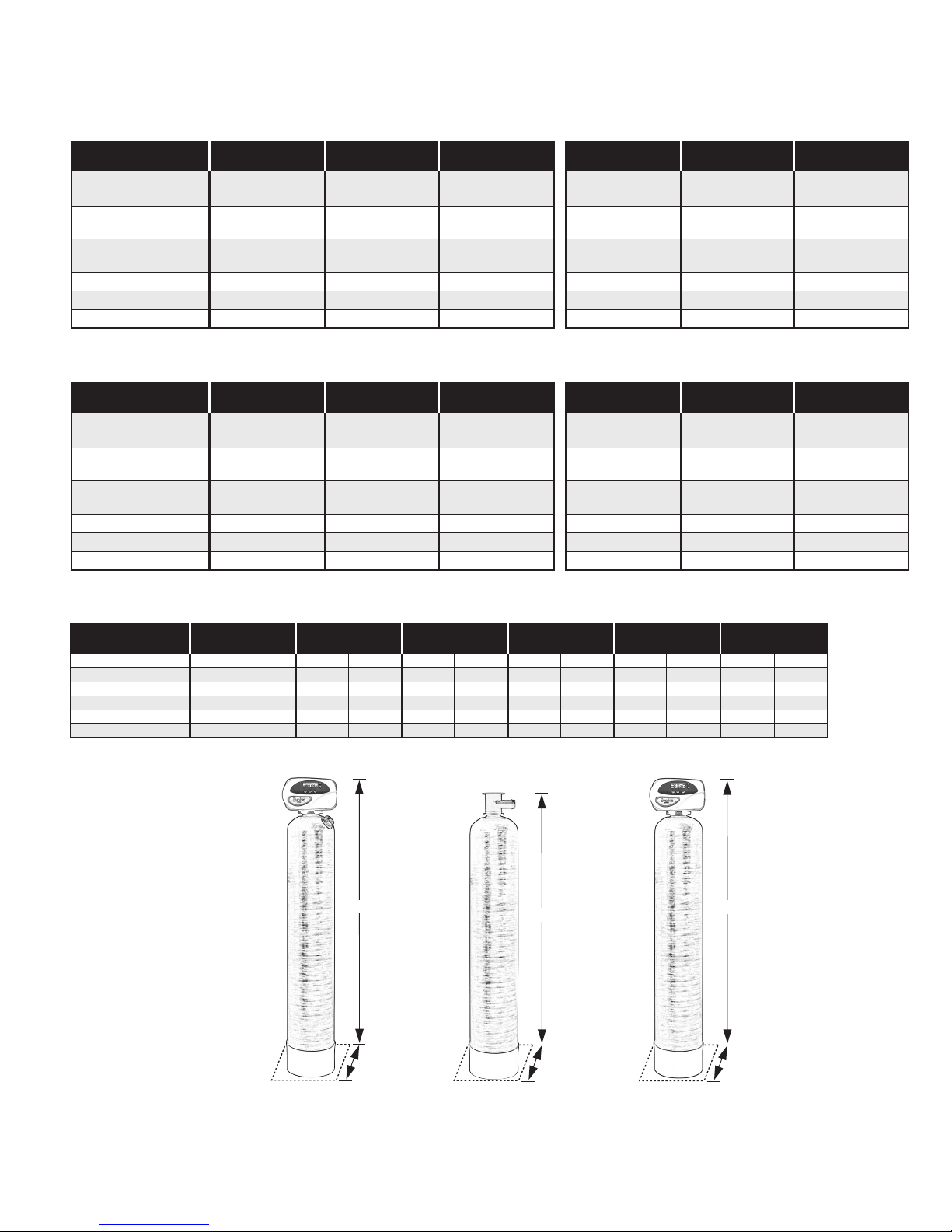
Total Dimensions 10”W x 62”H 12”W x 56”H 13”W x 62”H 10”W x 52”H 10”W x 62”H 13”W x 62”H
Shipping Weight Unit Filled 78 lb Unit Filled 109 lb Unit Filled 130 lb Unit Filled 100 lb Unit Filled 142 lb Unit Filled 185 lb
NOTE: The EVS and EVFE are approved for use in the State of Wisconsin.
1
Not tested at peak fl ow rate. Water quality may vary.
2
Iron removal may vary for hydrogen sulfi de systems, depending on local conditions.
3
Hydrogen sulfi de removal may vary for iron systems, depending on local conditions.
AIR CAT FILTERS
MODEL NUMBER EAG-1054 EAG-1248 EAG-1354 EACG-1054AN EACG-1248AN EACG-1354AN
Mineral Type Greensand Plus Greensand Plus Greensand Plus Greensand Plus/Calcite Greensand Plus/Calcite Greensand Plus/Calcite
1
Amount (Cu Ft) 1.0 1.5 2.0 1.0 1.5 2.0
Gravel Amount/Size (No. 1) 14 lb 1/4 x 1/8 21 lb 1/4 x 1/8 21 lb 1/4 x 1/8 14 lb 1/4 x 1/8 21 lb 1/4 x 1/8 21 lb 1/4 x 1/8
Gravel Amount/Size (No. 2) 7 lb #20 7 lb #20 7 lb #20 7 lb #20 7 lb #20 7 lb #20
Garnet Amount (Lbs) 13.0 19.0 22.0 13.0 19.0 22.0
Continuous Flow (GPM) 3.0 3.0 5.0 3.0 3.0 5.0
2
Peak Flow (GPM) 6.0 8.0 10.0 6.0 8.0 10.0
Backwash Flow (GPM) 6.5 9.0 11.0 6.5 9.0 11.0
3
Iron Removal 4.0 4.0 4.0 4.0 4.0 4.0
4
Hydrogen Sulfide Removal 0.5 0.5 0.5 0.5 0.5 0.5
pH Range Greater than 7.0 Greater than 7.0 Greater than 7.0 Greater than 6.3 Greater than 6.3 Greater than 6.3
Total Dimensions 10”W x 62”H 12”W x 56”H 13”W x 62”H 10”W x 52”H 10”W x 62”H 13”W x 62”H
Shipping Weight Unit Filled 78 lb Unit Filled 109 lb Unit Filled 130 lb Unit Filled 100 lb Unit Filled 142 lb Unit Filled 185 lb
1
Amount of acid neutralizing media may vary depending on local conditions.
2
Not tested at peak fl ow rate. Water quality may vary.
3
Iron removal may vary, depending on local conditions.
4
Hydrogen sulfi de removal may vary, depending on local conditions.
CYCLE TIMES AND USAGE
MODEL EVS-1054 EVS-1248 EVS-1354 EVFE-1054 EVFE-1248 EVFE-1354
MIN. GAL. MIN. GAL. MIN. GAL. MIN. GAL. MIN. GAL. MIN. GAL.
Backwash Air 4 16 4 23 4 27 4 16 4 23 4 27
Backwash 10 50 10 80 10 100 10 50 10 80 10 100
Regenerant Draw 60 25 60 40 60 50 60 25 60 40 60 50
Total 70 75 70 120 70 150 70 75 70 120 70 150
Height
Width
28
Page 29
ACID NEUTRALIZERS
MODEL NUMBER EVBF-1044AN EVBF-1054AN EVBF-1354AN EVAN-1044 EVAN-1054 EVAN-1354
Mineral Type Calcite or Mix Calcite or Mix Calcite or Mix Calcite or Mix Calcite or Mix Calcite or Mix
Amount (Cu Ft) 1.0 1.5 2.5 1.0 1.5 2.5
Gravel Amount/Size (No. 1) 14 lb 1/4 x 1/8 14 lb 1/4 x 1/8 21 lb 1/4 x 1/8 14 lb 1/4 x 1/8 14 lb 1/4 x 1/8 21 lb 1/4 x 1/8
Gravel Amount/Size (No. 2) 7 lb #20 7 lb #20 7 lb #20 7 lb #20 7 lb #20 7 lb #20
Continuous Flow (GPM) 4.8 4.8 6.9 5.0 5.0 6.0
Peak Flow (GPM) 11.0 11.0 16.0 8.0 9.0 12.0
Backwash Flow (GPM) 5.0 5.0 7.0 5.0 5.0 7.0
Total Dimensions 10”W x 52”H 10”W x 62”H 13”W x 62”H 10”W x 50”H 10”W x 60”H 13”W x 60”H
Shipping Weight Unit Filled 118 lb Unit Filled 169 lb Unit Filled 255 lb Unit Filled 100 lb Unit Filled 151 lb Unit Filled 237 lb
BACKWASHING FILTERS
MODEL NUMBER EVBF-1044 EVBF-1054 EVBF-1354 EVBF-1044 EVBF-1054 EVBF-1354
Mineral Type Carbon Carbon Carbon Turbidex Turbidex Turbidex
Amount (Cu Ft) 1.0 1.5 2.5 1.0 1.5 2.5
Gravel Amount/Size (No. 1) 14 lb 1/4 x 1/8 14 lb 1/4 x 1/8 21 lb 1/4 x 1/8 14 lb 1/4 x 1/8 14 lb 1/4 x 1/8 21 lb 1/4 x 1/8
Gravel Amount/Size (No. 2) 7 lb #20 7 lb #20 7 lb #20 7 lb #20 7 lb #20 7 lb #20
Continuous Flow (GPM) 5.0 5.0 6.0 6.0 7.0 11.0
Peak Flow (GPM) 8.0 9.0 12.0 10.0 11.0 18.0
Backwash Flow (GPM) 5.0 5.0 7.0 8.0 8.0 14.0
Total Dimensions 10”W x 52”H 10”W x 62”H 13”W x 62”H 10”W x 52”H 10”W x 62”H 13”W x 62”H
Shipping Weight Unit Filled 75 lb Unit Filled 90 lb Unit Filled 160 lb Unit Filled 85 lb Unit Filled 120 lb Unit Filled 190 lb
CYCLE TIMES AND USAGE
EVBF-1044 EVBF-1054 EVBF-1354 EVBF-1044 EVBF-1054 EVBF-1354
MODEL CARBON CARBON CARBON TURBIDEX TURBIDEX TURBIDEX
MIN. GAL. MIN. GAL. MIN. GAL. MIN. GAL. MIN. GAL. MIN. GAL.
Backwash 5 26.5 5 26.5 5 37.5 5 45 5 45 5 65
Rinse 1 5.3 1 5.3 1 7.5 1 9 1 9 1 13
Backwash 5 26.5 5 26.5 5 37.5 5 45 5 45 5 65
Rinse 1 5.3 2 10.6 2 15 1 9 2 18 2 26
Total 12 63.6 13 68.9 13 97.5 12 108 13 117 13 169
Height
Height
Height
Acid Neutralizer Upflow Neutralizer Backwashing Filter
Width
29
Width
Width
Page 30

Evolve Series® Water Conditioner Limited Warranty
Congratulations. You have purchased one of the nest water treatment systems available. In the unlikely event of
a problem due to defects in material and workmanship, Water-Right® proudly warrants our Evolve Series® water
conditioners to the original owner, at original installation location, when installed in accordance with Water-Right
speci cations from the date of original installation as follows:
For the LIFETIME of the original owner: Media tank, except for damages due to freezing,
high pressure (120 PSI and above), extreme temperature
(100° F and above) or a vacuum on the system.
For a period of TEN YEARS: Brine tank.
For a period of FIVE YEARS: Complete valve.
For a period of ONE YEAR: All other parts and components.
Any part found defective within the terms of this warranty will be repaired or replaced by the dealer at the
manufacturer’s discretion. You pay only freight from our factory and local dealer charges. To obtain local warranty
service, contact original dealer. If original dealer is unknown, contact Water-Right for authorized service dealer in
your area. If no authorized dealer is located in your area, please ship defective part or component freight prepaid to:
Water-Right, Inc.
1900 Prospect Ct.
Appleton, Wisconsin 54914
Water-Right, at its discretion, will repair or replace the part or component at its expense and return part freight collect.
The above provisions of the warranty are valid as long as the unit is connected in compliance with local plumbing
codes and in an equivalent manner and condition of the original installation and is owned by the original owner.
This warranty does not cover expendable or misapplied medias, or damages due to accident, re, ood,
freezing, or any other Act of God. Water-Right is not responsible for damages due to change in water conditions,
misapplication, misuse, neglect, vacuum, oxidizing agents, alteration, or lack of maintenance. No responsibility is
assumed for loss of use of the unit, inconvenience, loss or damage to real or personal property or any incidental
or consequential damages. Furthermore, we assume no liability and extend no warranties, express or implied,
for the use of this product with a non-potable water source. To the extent permitted by law, Water-Right
disclaims all implied warranties, including without limitation warranties of merchantability and tness for
particular purpose; to the extent required by law, any such implied warranties are limited in duration to
the period speci ed above for the speci ed components.
Some states do not allow limitations on how long an implied warranty lasts, so the above limitation may not apply
to you. Some states do not allow the exclusion or limitation of incidental or consequential damages, so the above
limitation or exclusion may not apply to you. This warranty gives you speci c legal rights, and you may also have
other rights which vary from state to state.
30
Page 31
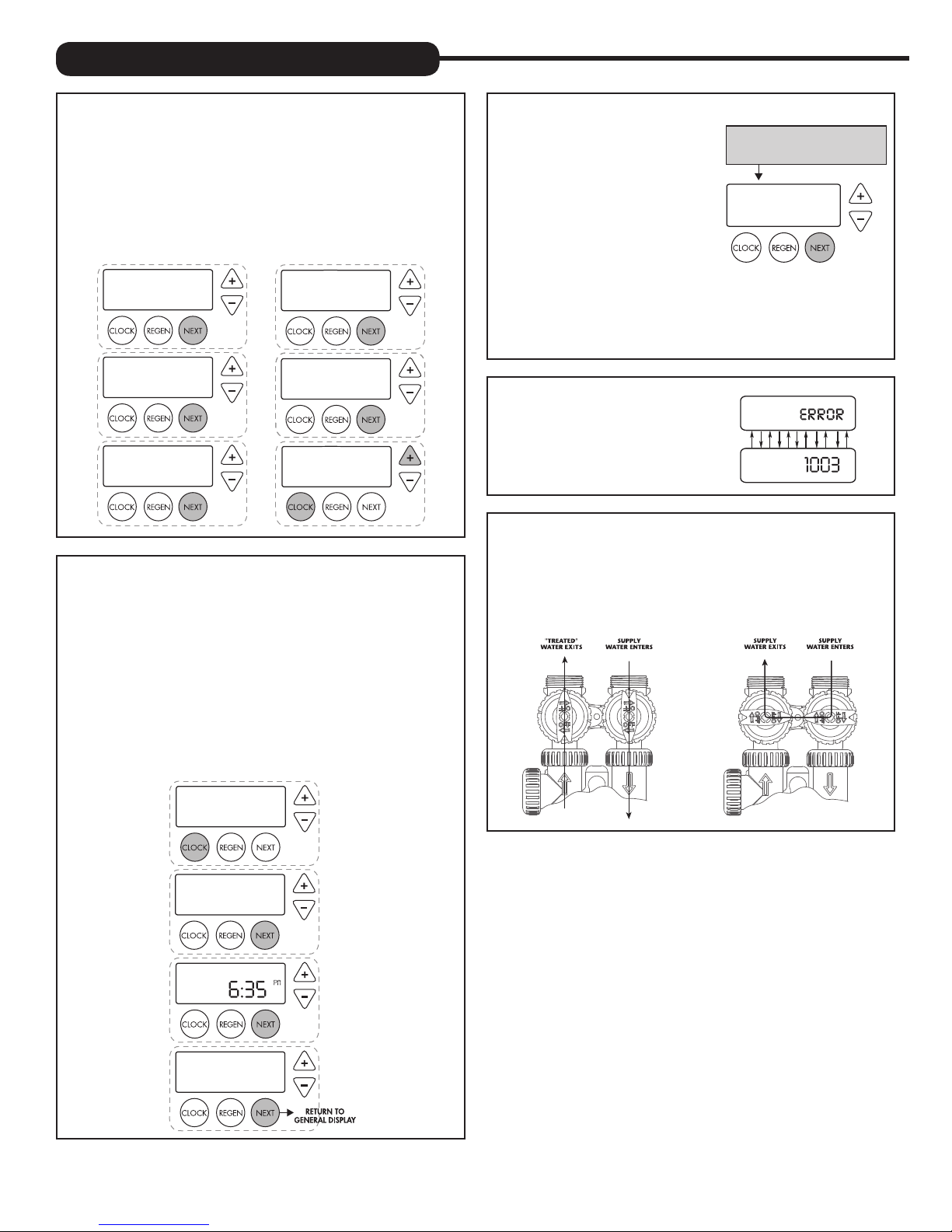
QUICK REFERENCE GUIDE:
GENERAL OPERATION
When the system is operating, one of six displays will be shown:
1. time of day/gpm
2. flow rate
3. vacation mode
4. capacity remaining
5. days to a regen
6. dealer name and phone number
Pressing
NEXT will toggle between the six choices.
TIME OF DAY MON
GPM
FLOW RATE
ON VACATION
2:408
8.0
GPM
NO
PM
CAPACITY REMAINING
GPM GAL
DAYS TO A REGEN
GPM
PHONE NUMBER
DEALER NA
1600
8
8
3
TO SET TIME OF DAY
In the event of a prolonged power outage, time of day flashes,
indicating that this needs to be reset. All other information will be
stored in memory no matter how long the power outage.
1. Accessed by pressing
2. Adjust hours with + and — buttons, AM/PM toggles at 12
3. Press NEXT
4. Adjust minutes with + and — buttons
5. Press NEXT
6. Adjust current day with + and — buttons
7. Press
NEXT to complete and return to normal operation
SET CLOCK
MANUAL REGENERATION
NOTE: For softeners, if brine tank does
not contain salt, fill with salt and wait
at least two hours before regeneration.
If you need to initiate a manual
regeneration, either immediately, or the
same night at the preprogrammed time
for regeneration (typically 2:00 AM),
complete the following steps.
For Immediate Regeneration:
Press and hold
starts (typically 3 seconds).
For Regeneration the same night:
Press and release
REGEN until valve motor
REGEN (notice that flashing “REGEN TODAY” appears).
REGEN TODAY and TIME OF DAY
will flash alternately if a regeneration
is expected tonight.
REGEN TODAY MON
GPM
PM
2:408
ERROR
If the display toggles between “Error”
and an error code (i.e. a number), call
a service technician and report the
error code.
BYPASS VALVE OPERATION
To shut off water to the system, position arrow handles as shown in
the bypass operation diagram below. If your valve doesn’t look like
the diagram below, contact your service technician for instructions
on how to shut off water.
NORMAL OPERATION BYPASS OPERATION
TIME HOUR
SET
TIME MINUTES
SET
CURRENT DAY
SET
2:00
MON
AM
31
Page 32
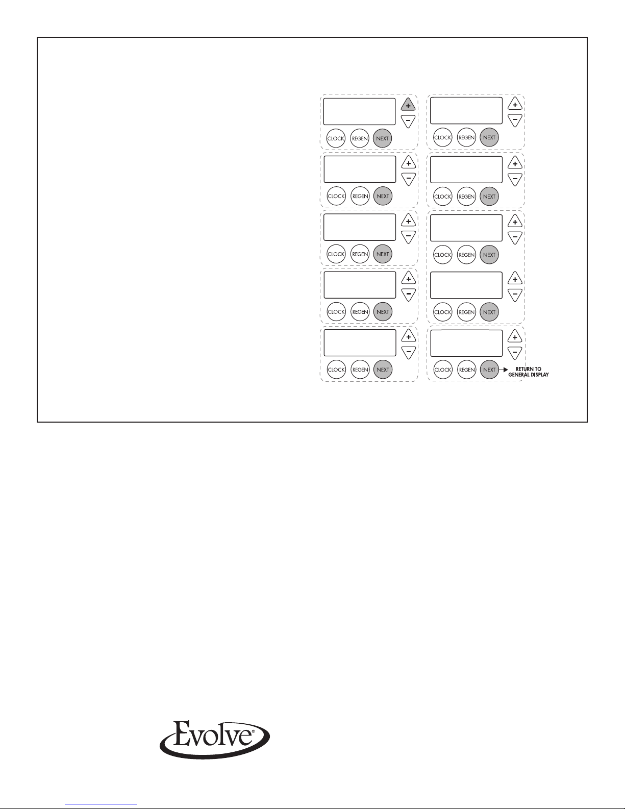
ADJUST HARDNESS, DAYS BETWEEN REGENERATION, TIME OF REGENERATION AND ALARM BUZZER
For initial set-up or to make adjustments, please complete the following steps.
1. Accessed by pressing
2. Adjust hardness using + and — buttons
3. Press
NEXT
4. Adjust days between regenerations using + and — buttons
5. Press
NEXT
6. Adjust time of regeneration hour with + and — buttons,
AM/PM toggles at 12.
7. Press NEXT
8. Adjust time of regeneration minutes with + and — buttons
9. Press
NEXT
10. Turn service alarm time ON with + and — buttons.
Default is OFF.
11. Press NEXT twice
12. Turn service alarm gallons ON with + and — buttons.
Default is OFF.
13. Press
NEXT twice
14. Turn alarm buzzer ON or OFF with + and — buttons.
15. Press
NEXT
16. Adjust alarm buzzer start time with + and — buttons.
17. Press NEXT
18. Adjust alarm buzzer end time with + and — buttons.
19. Press
NEXT
20. Turn display backlight ON or OFF with + and — buttons.
Default is ON.
21. Press
NEXT to complete and return to normal operation.
NEXT and + button simultaneously
WATER HARDNESS
SET
DAYS BETWEEN REGEN
SET
REGEN TIME HOUR
SET
REGEN TIME MINUTES
SET
20
6
2:00
2:00
SERVICE ALARM GAL
SET
SERVICE ALARM TIME
GR
AM
AM
SET
ALARM BUZZER START
SET
ALARM BUZZER END
SET
LIGHT NORMALLY
SET
OFF
OFF
6:00
8:00
ON
AM
PM
© 2014 Evolve Series All rights reserved.
LIT-EV FILT MAN ENVINK 3/14 1M
Manufactured exclusively for Evolve Series Dealers at:
1900 Prospect Court • Appleton, WI 54914
Phone: 920-739-9401 • Fax: 920-739-9406
 Loading...