

Page 1

Users Instructions
Installation &
Servicing
Instructions
THESE INSTRUCTIONS
TO BE RETAINED
BY USER
Vokèra is a licensed member of the Benchmark scheme
which aims to improve the standards of installation and
commissioning of domestic hot water systems in the UK.
evolve
High efciency combi boiler
evolve 24C G.C. N° 47-364-37
evolve 28C G.C. N° 47-364-38
evolve 32C G.C. N° 47-364-39
evolve 36C G.C. N° 47-364-40
Page 2

2
1. THINGS YOU SHOULD KNOW ................................................... 3
2. GETTING STARTED ....................................................................5
3. HOW TO.... .................................................................................12
4. WHAT IF ..................................................................................... 13
SECTION 1 - DESIGN PRINCIPLES AND OPERATING
SEQUENCE ...................................................................................15
SECTION 2 - TECHNICAL DATA ..................................................16
SECTION 3 - CONTROL PANEL (REC10) .................................... 19
SECTION 4 - GENERAL REQUIREMENTS (UK) .........................25
SECTION 4A - GENERAL REQUIREMENTS (EIRE) ....................26
SECTION 5 - INSTALLATION .......................................................28
SECTION 6 - COMMISSIONING ...................................................34
SECTION 7 - SERVICING INSTRUCTIONS .................................. 50
SECTION 8 - CHECKS, ADJUSTMENTS AND FAULT FINDING ....57
SECTION 9 - LPG INSTRUCTIONS .............................................. 62
Commissioning checklist ............................................................ 64
Benchmark ...............................................................................65-67
RANGE RATED
This boiler can be adapted to the heat requirements of the system,
and in fact it is possible to set the range rated parameter as shown
in the specic paragraph.
After setting the desired output report the value in the table on the
back cover of this manual, for future references.
Page 3

3
1.1 GAS APPLIANCES
Gas Safety (Installation and Use) Regulation (UK).
In the interests of your safety and that of others it is a legal
requirement that all gas appliances are installed and correctly
maintained by a competent person and in accordance with the
latest regulations.
1.2 ELECTRICAL SUPPLY
Please ensure that this appliance has been properly connected
to the electrical supply by means of a double pole isolator or
un-switched socket, and that the correct size of fuse (3 AMP)
has been tted.
Warning: this appliance must be earthed!
1.3 WARRANTY REGISTRATION
Please take the time to register the appliance warranty using
the documentation provided, call 0800 479 0754 (UK) or 056
7755055 to obtain your warranty conrmation code (please
have your appliance warranty card to hand).
1.4 APPLIANCE COMMISSIONING CHECKLIST
(UK only)
The Benchmark checklist section can be found at the rear of
the appliance installation booklet. This important document
must be completed during the installation/commissioning of
your boiler. All GAS SAFE registered installers carry a GAS
SAFE ID card, and have a registration number. These details
should be recorded in the Benchmark commissioning checklist
section within the installation booklet. You can check your
installers details by calling GAS SAFE direct on 08004085500.
Failure to install and commission the appliance in accordance
with the manufacturers instructions will invalidate the warranty.
This does not affect your statutory rights.
1.5 HOW DOES IT WORK?
Your evolve boiler supplies heated water to your radiators
and hot water to your hot water taps. The central heating is
controlled via a time clock and any thermostats that your installer
may have tted. The boiler will light when it receives a request
from the time clock via any thermostat that may be installed, or
whenever a hot water outlet (tap) is opened. Your evolve boiler
lights electronically and does not have a pilot light.
In the unlikely event of a fault developing with your boiler, the
supply of gas to the burner will be terminated automatically.
USERS INSTRUCTIONS
Dear Customer
Your Vokèra evolve boiler has been designed to meet and exceed the very latest standards in gas central heating technology,
and if cared for, will give years of reliable use and efciency.
Please therefore take some time to read these instructions carefully.
Do’s and Don’t’s
- Do ensure that the system pressure is periodically checked
- Do ensure that the boiler is not used by children or unassisted disabled people
- Do ensure that you know how to isolate the appliance in an emergency
- Do ensure that you are familiar with the appliance controls
- Do ensure that your installer has completed the appliance log book section
- Do not attempt to remove the appliance casing or gain internal access
- Do not hang clothes etc. over the appliance
- Do not forget to have the appliance serviced annually.
This booklet is an integral part of the appliance. It is therefore necessary to ensure that the booklet is handed to the person
responsible for the property in which the appliance is located/installed.
A replacement copy can be obtained online from www.vokera.co.uk & www.vokera.ie
.
INTRODUCTION
1. THINGS YOU SHOULD KNOW
1.7 CLEARANCES REQUIRED
ABOVE 100mm*
BELOW 100mm^
LEFT SIDE 2mm
RIGHT SIDE 2mm**
FRONT 4mm***
evolve 24C - 28C 32C - 36C
HEIGHT 740 mm 740 mm
WIDTH 420 mm 420 mm
DEPTH 275 mm 350 mm
1.6 DIMENSIONS
* 100mm if rear-ue outlet is used or 25mm above ue bend if top
ue outlet is used. Consideration should be given to providing
reasonable clearance for the insertion of a FGA probe.
** Disconnection of adjacent components may be required in order
to facilitate syphon removal.
*** Provided that a door or removal panel enables 450mm access for
maintenance.
^ Can be reduced to 5mm if a removal panel enables 100mm for
maintenance.
100
25
2
2
100
1.8 FROST PROTECTION SYSTEM
The evolve is equipped with a built-in frost protection system,
this enables the boiler to over-ride the time controls – even if
switched off – and operate the burner and/or pump, should
the temperature within the appliance drop below 5 °C. Please
note that the frost protection system is designed to protect the
appliance only, should frost protection be required for the heating
system, additional controls may be required.
NOTE
The frost protection system is reliant on the appliance having a
permanent electrical supply, and being in a non-fault condition.
1.9 APPLIANCE STATUS INDICATORS
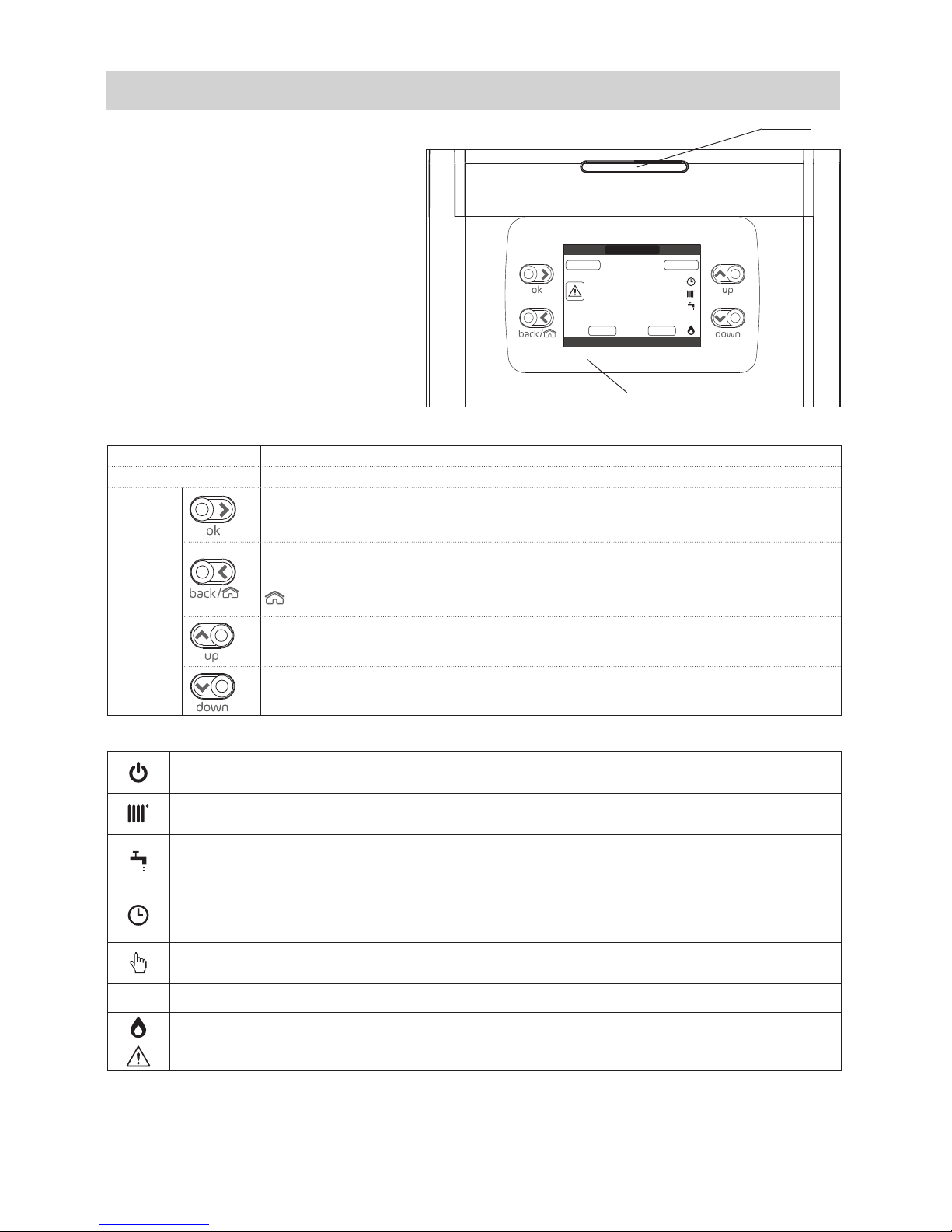
Your appliance incorporates the REC 10 UI (User Interface),
that displays information on appliance status and condition.
Page 4
4
Depending on the type of application, some of the functions described in this manual might not be available.
The REC 10 UI is a multi-functional control that
enables you to view the operating status of your
appliance at a glance; and is also used to adjust/set
the various ‘User’ settings, including temperature setpoints.
The REC 10 UI also incorporates an embedded timer
that - if enabled - can be used to program and control
the ON/OFF times for your central heating. Please
consult you installer for further advice on this function.
The REC 10 UI features a backlit liquid crystal display.
LED
Light signal indicating the operating status of the boiler. Can be red or green (see specific paragraph)
REC10
Boiler control panel
Key area
ok= confirm
back= ret
urn to the previous screen
cancel selection
return to the main screen (press > 2 sec.)
up= allows you to choose between the options PLANT-STATE-SET-INFO-MENU and to
surf through the
submenus
scrolling upwards
down= allows you to choose between the options PLANT-STATE-SET-INFO-MENU and to
surfe through the
submenus
scrolling down
This icon indicates that the OFF operating status mode has been set. Each ignition request is ignored except for the frost-protection
function. The pump anti-lock, 3-way valve and frost-protection function remain active.
This icon indicates that WINTER mode has been selected (HEATING function enabled). If a heating request from the main zone is in
progress, the icon will be flashing.
This icon indicates that the circuit for domestic hot water production is enabled. When a domestic hot water request is in progress, the
icon flashes. The “P” at the top of the domestic hot water icon indicates that the boiler preheating function is enabled; the “P” when
flashing indicates that a preheating request is in progress.
When the “central heating programming timing” is enabled this icon indicates that the system heating (main zone) is in AUTOMATIC
mode (the management of the heating requests follows what has been set with the timer).
If the heating function is not enabled during the current time frame, the icon will be crossed out.
When the “central heating programming timing” is enabled this icon indicates that the system heating (main zone) is in MANUAL mode
(the management of the heating requests does not follow what has been set with the programming timing, but it is always active).
OFF
This icon indicates that the system (main zone) has been set to off (not active).
This icon indicates that the system is detecting the presence of a flame.
This icon indicates the presence of an anomaly or fault condition, and is always flashing.
Note:
The temperature of the hot water sensor is shown at the centre of the main screen. The value’s meaning is indicated at the bottom of the display.
Whenever a heating request is in progress, the value displayed at the centre of the screen refers to the system’s ow sensor, with the relative
indication.
The value expressed in bar refers to the system’s water pressure.
The top of the screen shows the current date and time, as well as the outdoor temperature, if available.
System Icons may appear on both the left and right of the display; and they signify the following condition/status:
LED
REC10
FRI
18/05/2013 12:17
MENU
INFO SET
PLANT
HOT WATER TEMPERATURE
STATE
42
°C
P
1.3
bar
CONTROL PANEL (REC10)
Fig. 1
Page 5
5
2. GETTING STARTED
2.1 BEFORE SWITCHING ON
Be
fore switching the appliance on, please familiarise yourself with:
- how to isolate the appliance from the gas, water, and electricity
supplies;
- how to check and top-up – if necessary – the system water
pressure;
- any external thermostats and their functions;
- the appliance controls.
2.2 APPLIANCECONTROLS(seeg.1)
The appliance controls are concealed behind the front ap of
the appliance.
NOTE
The appliance frost protection is active in all the boiler modes.
The control panel functions can be used to vary the
temperature of the water that circulates around your radiators
and the water that ows from your hot water taps.
The heating temperature range can be adjusted between 20C
- 40C (low temperature) or 40C - 80C (high temperature) this
range is congured by your installer and the default is the high
temperature range. The hot water temperature range can be
adjusted between 37C - 60C.
Please Note: the actual delivery temperature is also conditional
upon the incoming water temperature and the actual ow-rate
at the outlet.
Refer to the main appliance status table for fault indicator and
boiler status.
2.3 LIGHTING THE BOILER
Ensure the gas and electrical supply to the boiler are
turned on.
After completing all operations required to prepare
commissioning, proceed as follows to start the boiler.
2.4 START SCREEN
When the appliance is first connected to the electrical supply,
the REC 10 may require you to set the time and date (see
2.9.1), and the appliance will enter its ‘pre-purge’ mode that
will last for several minutes. On completion of the ‘pre-purge’
phase, the appliance will enter its ‘standby’ mode unless a
heating or HW request has been made.
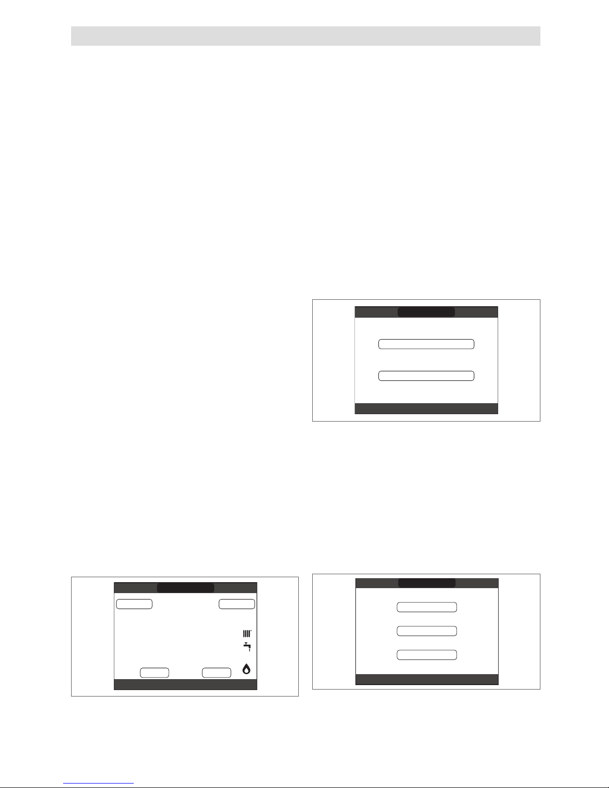
By pressing the “up” and “down” keys it is possible to move
the selection of the functions in this order:
- PLANT
- STATE
- SET
- INFO
- MENU.
By pressing the “ok” key you can access the settings of the
selected function (except for PLANT).
The “back” key is inactive (except for PLANT).
18/05/2013 12:17
MENU
INFO SET
42
°C
1.3
bar
FRI
PLANT
HOT WATER TEMPERATURE
STATE
2.5 PLANT
The PLANT menu only becomes available if additional zones
have been added and congured with this system via the
REC10 H.
In order to change zones (see above), highlight PLANT if
necessary pressing the “up” and “down” keys.
Then, pressing the “ok” and “back” keys, it will be possible
to select the other zones in this sequence (only if added and
congured with the REC10 H):
- PLANT
- MAIN ZONE
- ZONE 1
- ZONE 2.
The TIME AND DATE, LANGUAGE and BACKLIGHT settings
are are related to the appliance only.
The information contained in the INFO menu is related to the
appliance.
No domestic hot water parameters can be set if MAIN, ZONE 1
or ZONE 2 is selected.
2.6 STATE
The STATE function can be used to set the BOILER and
MAIN ZONE operating modes.
To do this, it is necessary to highlight the desired entry using
the “up” and “down” keys and then pressing “ok” to conrm
the selection.
Pressing “back” takes you back to the initial screen without
making any selection.
BOILER
STATE
MAIN ZONE
2.6.1 Boiler
This function can be selected in order to set the boiler’s status,
by choosing one of the following options:
- OFF
- SUMMER
- WINTER.
The highlighted status is that which is currently selected. In
order to select a different status highlight it using the “up” and
“down” keys and then press “ok” to conrm the selection.
Once the selection has been validated, the display returns to
the STAT E screen.
Press “back” to return to the start screen without making any
selection.
OFF
SUMMER
BOILER
WINTER
OFF: if OFF is selected, the system enters the standby mode,
whereby only the standby functions remain active.
SUMMER: if SUMMER is selected, the system produces
domestic hot water. Heating is disabled.
WINTER: if WINTER is selected, the system produces
domestic hot water and activates the heating function.
Page 6
6
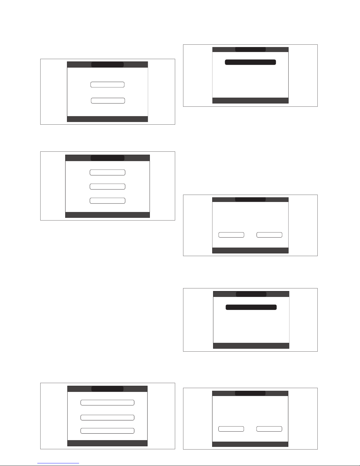
2.6.2 Main zone
Selecting this function allows you to set the main zone’s
status, by choosing one of the following options:
- if the embedded time clock is disabled (default):
- ZONE ON: boiler responds to heating request
- ZONE OFF: boiler does not respond to any request for
heating
ZONE ON
MAIN
ZONE OFF
- if the embedded time clock has been enabled:
- AUTO
- MANUAL
- HEAT OFF.
AUTO
MANUAL
MAIN
HEAT OFF
In order to select a different status highlight it using the “up”
and “down”keys and confirm the selection by pressing “ok”.
Once the selection has been validated, the display returns to
the STAT E screen.
Press “back” to return to the S TATE screen without making
any selection.
ON: if ON is selected, the zone heating requests are met.
AUTO: if AUTO is selected, the zone heating requests will be
managed based on the scheduled programme.
MANUAL: if MANUAL is selected, the zone requests will be
managed based on the selection set by the user.
HEAT OFF: If HEAT OFF is selected, the zone heating
requests will be ignored.
NOTE: if you want to deactivate the zone in SUMMER or in
WINTER, you must select the required season (SUMMER or
WINTER in the BOILER menu) and set the zone concerned
to OFF.
2.7 SET
With the SET function it is possible to congure the HEATING,
HOT WATER and PREHEATING setpoints.
To do this, it is necessary to highlight the desired entry using
the “up” and “down” keys and then pressing “ok” to conrm
the selection. Pressing “back” takes you back to the initial
screen without making any selection.
HEATING
SET
HOT WATER
PREHEATING
2.7.1 Heating
Press the “up” and “down” keys to change the heating
setpoint temperature and conrm the selection by pressing
“ok”. Press “back” to return to the SET screen without
making any selection.
SET
HEATING
78,0
°C
When an outdoor temperature sensor is installed, the outlet
setpoint temperature is automatically adjusted by the system,
in order to maintain the ambient temperature according to any
variations in the outdoor temperature. If you want to adjust
the outlet temperature, raising it or lowering it with respect
to that automatically calculated by the boiler, it is possible to
change the HEATING setpoint selecting the desired comfort
level within the range (-5 ÷ +5).
The user is then asked to confirm the setpoint setting: select
CONFIRM or CANCEL using the “up” and “down” keys, and
confirm the selection pressing “ok”.
Once the selection is confirmed, the display returns to the
SET screen.
If the selection is cancelled or the “back” key is pressed you
return to the previous SET screen.
SET
THE PARAMETER
WILL BE CHANGED
CONFIRM CANCEL
CONFIRM OR DELETE
SELECTION
2.7.2 Hot water
Press the “up” and “down” keys to change the boiler’s
domestic hot water setpoint. Press “ok” to conrm the
selection. Press “back” to return to the SET screen without
making any selection.
SET
HOT WATER
58,0
°C
The user is then asked to conrm the setpoint setting: select
CONFIRM or else CANCEL using the “up” and “down” keys
and conrm with “ok”.
Once the selection is conrmed, the display returns to the
previous SET screen. If the selection is cancelled or the
“back” key is pressed you return to the SET screen.
SET
THE PARAMETER
WILL BE CHANGED
CONFIRM OR DELETE
SELECTION
CONFIRM CANCEL
Page 7
7
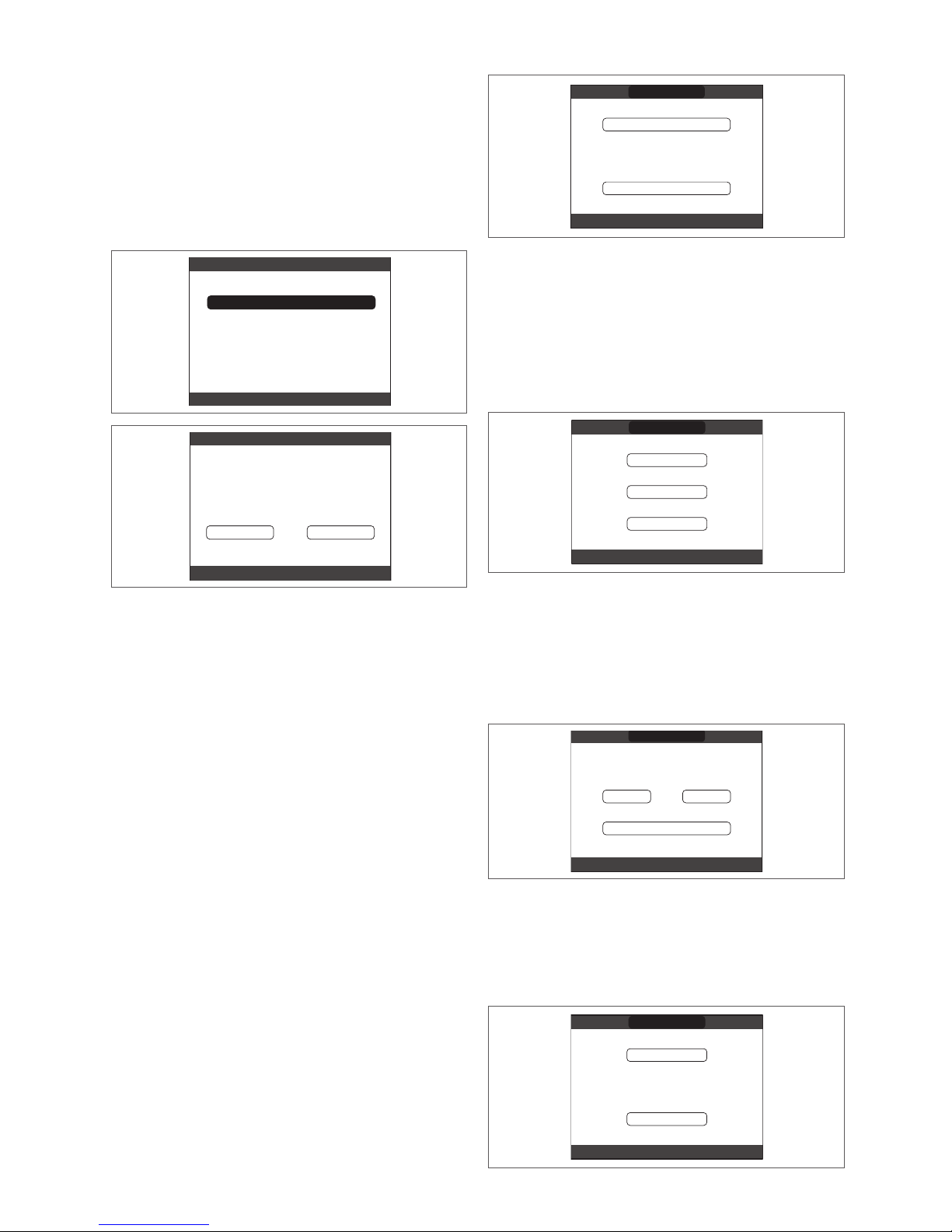
2.7.3 Preheating
This function keeps the water in the domestic hot water
exchanger hot, to reduce standby times when a request is
made. When the preheating function is enabled, the symbol
P comes on with a steady light at the top of the domestic
hot water icon. During burner ignition following a preheating
request, the symbol P starts flashing.
It is possible to access the PREHEATING function selecting
SET on the main screen of the REC10. Setting PREHEATING
= 1 the boiler’s domestic hot water function activates.
To deactivate the preheating function, set the parameter to
PREHEATING = 0, the symbol P switches off.
The function is not active when the boiler is OFF.
TERMOSTATI SAN
PREHEATING
0
THE PARAMETER
WILL BE CHANGED
CONFIRM CANCEL
CONFIRM OR DELETE
SELECTION
2.8 INFO
The INFO function can be used to display a series of data
regarding the system.
ATTENTION - The displayed data is for information only and
cannot be modied.
Press the “up” and “down” keys to go through the list of
information available, in this order:
- SCREED HEATER OPERATING HOURS (*)
- CH PROBE
- RETURN PROBE
- DHW PROBE
- EXHAUST PROBE
- OUTDOOR TEMPERATURE SENSOR (*)
- EXT T FOR THERMOREG (*)
- FLOWMETER
- FAN SPEED
- ZONE 1 DELIVERY (*)
- ZONE 2 DELIVERY (*)
- EXHAUST PROBE HOURS
- MAIN ZONE SET-POINT
- SET MAIN ZONE
- ZONE 2 SET-POINT (*)
- WATER PRESSURE.
The “ok” key is inactive.
The “back” key allows you to return to the initial screen.
(*) In the absence of additional zones or if the screed heater
function is not operating, the relative information will not be
displayed.
2.9 MENU
Using the MENU it is possible to access the conguration of
the SETTINGS and the TIME SCHEDULE (available only if
the embedded timer is enabled (POR=1).
To do this, it is necessary to highlight the desired entry using
the “up” and “down” keys and then pressing “ok” to conrm
the selection.
Pressing “back” takes you back to the initial screen without
making any selection.
MON
18/11/2013 12:17
SETTINGS
MENU
SELECT OPTION
TIME SCHEDULE
2.9.1 Settings
Select this function to modify the following settings:
- TIME AND DATE
- LANGUAGE
- BACKLIGHT.
To access the desired setting, it is necessary to highlight it
using the “up” and “down” keys and then pressing “ok” to
conrm the selection.
Press “back” to return to the start screen without making any
selection.
TIME & DATE
LANGUAGE
SETTINGS
SELECT OPTION
BACKLIGHT
TIME AND DATE
Press “ok” to highlight in sequence HOURS, MINUTES, DAY,
MONTH, YEAR and press the “up” and “down” keys to
change the desired values.
Once the sequence has nished by pressing “ok”, the settings
will be saved and the display will return to the initial screen.
By pressing “back” at any time the system will return to the
SETTINGS cancelling the changes that were made.
12 17:
ENTER TIME AND DATE
TIME & DATE
USE THE ARROWS TO MODIFY
18 / 11 / 2013
LANGUAGE
Press the “up” and “down” keys to select the desired
language.
Pressing “ok” the language selection is conrmed and the
display returns to the initial screen.
Pressing “back” the system returns to the SETTINGS screen
without changing the system’s language.
ENGLISH
LANGUAGE
SELECT LANGUAGE
ITALIANO
Page 8
8
BACKLIGHT
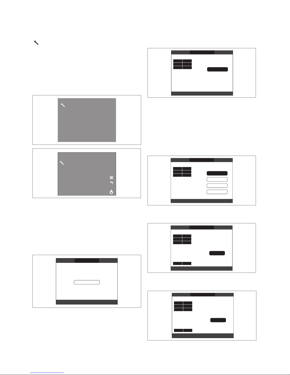
The screen saver display (backlight off) is automatically
activated when the time, that has been set in parameter \
MENU \ SETTINGS \ BACKLIGHT, elapsed without having
pressed any buttons.
In the screen saver the current time is normally displayed.
“ ” symbol and the number of days to STOP appear if the
AUTOSTOP function is active.
When there is a heat request, the current time is replaced with
the boiler ow temperature and turns on the icon concerning
the type of request in progress.
A system efciency indicator is also displayed at the top of
the screen:
- HIGH EFFICIENCY (if the average value of the return probe
> 55°C)
- OPTIMUM EFFICIENCY (if average value of the return
probe < 55°C).
: 30 days
05:11
42
OPTIMUM EFFICIENCY
°C
: 30 days
P
2.9.2 Time schedule
This function can only be selected if the embedded clock has
been enabled (POR=1), it is possible to change the following:
- MAIN.
To access the desired timer programme, it is necessary to
highlight the relevant zone, e.g. MAIN, using the “up” and
“down” keys and then pressing “ok” to conrm the selection.
Press “back” to return to the start screen without making any
selection.
For a detailed description of the scheduled programming
timer, please refer to the section
“2.10 TIME SCHEDULE”
.
MON
18/11/2013 12:17
MAIN
SCHEDULE
SELECT THE ZONE
2.10 TIME SCHEDULE
Select the desired day using the “up” and “down” keys.
A table will be displayed indicating the day and the time
settings that have been pre-programmed. Press “ok” to
access the programming for the selected day.
Pressing “back” takes you back to the initial screen without
making any selection.
SELECT
A DAY
START
MAIN
THURSDAY
07:30
11:30
18:00
END
08:30
13:30
22:30
ZONE SCHEDULE
Once the selection has been made, the user can choose from
among the following options:
- ADD: you can add up to four start & end periods
- MODIFY
- DELETE
- COPY.
2.10.1 Add
This function serves to add a new time frame to the selected
day (up to a maximum of 4).
Press “ok” to select the function, after having highlighted it (if
necessary) using the “up” and “down” keys.
START
MAIN
ADD
THURSDAY
MODIFY
DELETE
COPY
07:30
11:30
18:00
END
08:30
13:30
22:30
SELECT OPTION
Press the “up” and “down” keys to increase or decrease
by 30 minutes the start time and press “ok” to conrm the
selection.
START
MAIN
THURSDAY
ADD
PERIOD
ENTER
START TIME
14:00
07:30
11:30
18:00
END
08:30
13:30
22:30
USE THE ARROWS TO MODIFY
Press the “up” and “down” keys to increase or decrease
by 30 minutes the end time and press “ok” to conrm the
selection.
START
MAIN
THURSDAY
ADD
PERIOD
ENTER
END TIME
15:00
07:30
11:30
18:00
END
08:30
13:30
22:30
USE THE ARROWS TO MODIFY
14:00
Page 9

9
In order to conrm that the operation has been completed
successfully, the display will show the table with the new time
frame ashing.
MAIN
USE THE ARROWS TO MODIFY
START
THURSDAY
07:30
11:30
14:00
END
08:30
13:30
15:00
18:00 22:30
ADD
MODIFY
DELETE
COPY
2.10.2 Modify
This function serves to edit a time frame already present for
the selected day.
Press “ok” to select the function, after having highlighted it (if
necessary) using the “up” and “down” keys.
START
MAIN
ADD
THURSDAY
MODIFY
DELETE
COPY
07:30
11:30
18:00
END
08:30
13:30
22:30
SELECT OPTION
Press the “up” and “down” keys to select the desired time
band and press “ok” to conrm the selection.
START
MAIN
THURSDAY
SELECT
PERIOD TO
MODIFY
07:30
07:30
11:30
18:00
END
08:30
13:30
22:30
USE THE ARROWS TO MODIFY
Press the “up” and “down” keys to increase or decrease
by 30 minutes the start time and press “ok” to conrm the
selection.
START
MAIN
THURSDAY
11:30
07:30
11:30
18:00
END
08:30
13:30
22:30
USE THE ARROWS TO MODIFY
ENTER
START TIME
Press the “up” and “down” keys to increase or decrease
by 30 minutes the end time and press “ok” to conrm the
selection.
START
MAIN
THURSDAY
14:00
07:30
11:30
18:00
END
08:30
13:30
22:30
USE THE ARROWS TO MODIFY
ENTER
END TIME
In order to conrm that the operation has been completed
successfully, the display will show the table with the new time
frame ashing.
At this point the user can select a new time frame to be
modied, or else can press “back” to return to the previous
TIME SCHEDULE screen.
START
MAIN
THURSDAY
SELECT
PERIOD TO
MODIFY
07:30
07:30
11:30
18:00
END
08:30
14:00
22:30
USE THE ARROWS TO MODIFY
2.10.3 Delete
This function serves to delete a time frame already present for
the selected day.
Press “ok” to select the function, after having highlighted it (if
necessary) using the “up” and “down” keys.
START
MAIN
THURSDAY
07:30
11:30
18:00
END
08:30
13:30
22:30
SELECT OPTION
ADD
MODIFY
DELETE
COPY
Press the “up” and “down” keys to select the desired time
band and press “ok” to conrm the selection.
START
MAIN
THURSDAY
SELECT
PERIOD TO
DELETE
07:30
11:30
18:00
END
08:30
13:30
22:30
USE THE ARROWS TO MODIFY
To conrm or cancel the selection made, highlight the
corresponding option and conrm it by pressing “ok”.
In order to conrm that the operation has been completed
successfully, the display will show the table with the selected
time frame ashing just before deleting it from the table.
START
MAIN
THURSDAY
ARE YOU SURE
TO DELETE
THE PERIOD ?
END
CONFIRM OR DELETE SELECTION
07:30
11:30
18:00
08:30
13:30
22:30
CONFIRM
CANCEL
Page 10
10
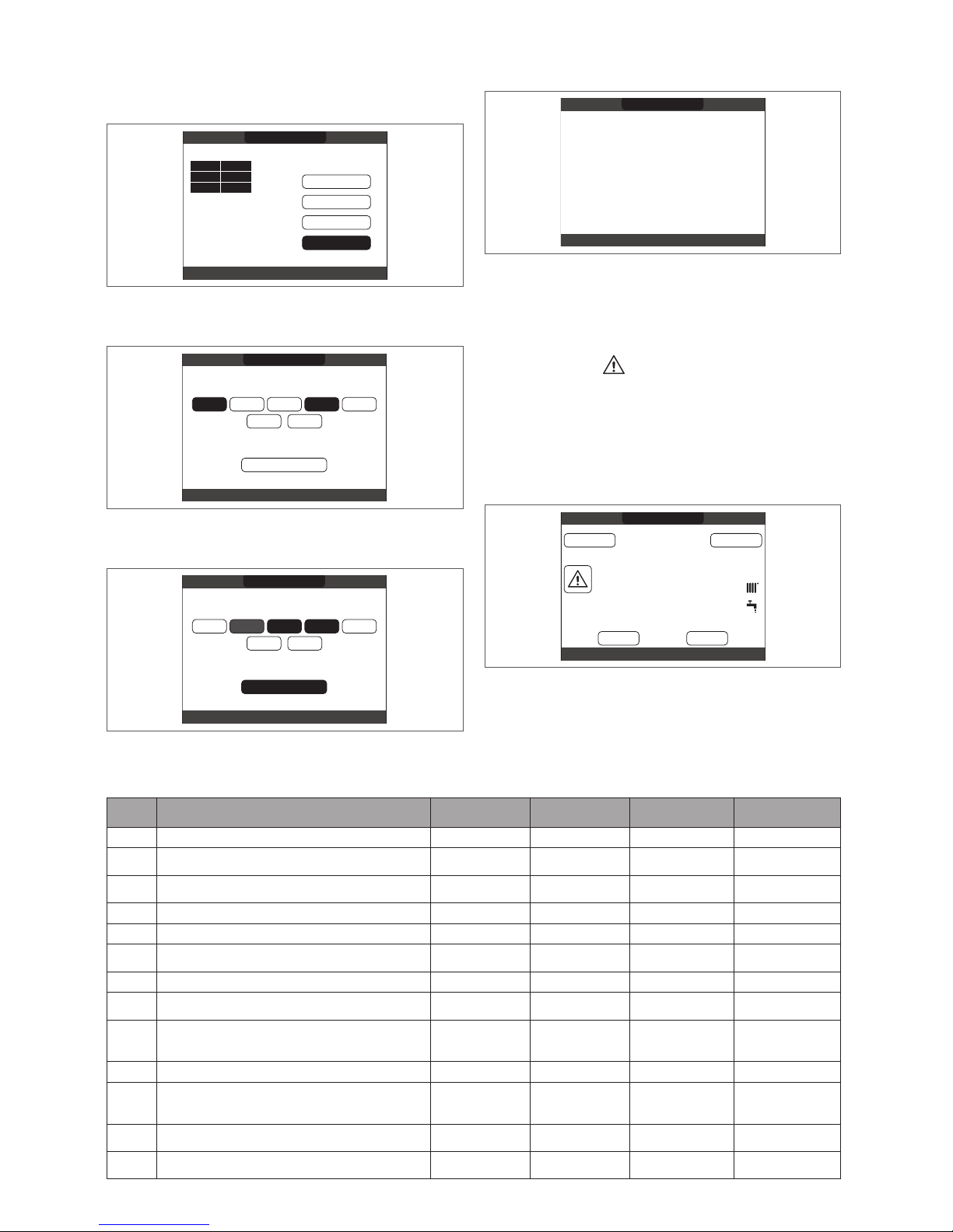
2.10.4 Copy
This function serves to copy the same scheduled programme
for other days of the week.
Press “ok” to select the function, after having highlighted it (if
necessary) using the “up” and “down” keys.
START
MAIN
THURSDAY
07:30
11:30
18:00
END
08:30
13:30
22:30
SELECT OPTION
ADD
MODIFY
DELETE
COPY
Press the “up” and “down” keys to select the day on which
to copy the hourly schedule to and press “ok” to conrm the
selection.
CONFIRM
MON TUE WED THU
SAT SUN
FRI
MAIN
SELECT DAYS ON WHICH YOU WANT
TO COPY SCHEDULE OF THURSDAY
USE THE ARROWS TO MODIFY
The day will be highlighted and others can be selected using
the same procedure.
When nished highlight CONFIRM and press “ok”.
CONFIRM
MON TUE WED THU
SAT SUN
FRI
MAIN
SELECT DAYS ON WHICH YOU WANT
TO COPY SCHEDULE OF THURSDAY
USE THE ARROWS TO MODIFY
In order to conrm that the operation has been completed
successfully, the display will show the list of days to which the
scheduled programme has been copied.
MAIN
SCHEDULE OF THURSDAY
WILL BE COPIED ON THE DAYS :
TUESDAY
USE THE ARROWS TO MODIFY
2.11 FAULTS
Should a fault occur, a screen will appear on the display
indicating the relative error code and a brief alphanumeric
description of the fault. Pressing the “back” button it is
possible to return to the main screen, where a fault is signalled
by this ashing icon .
The user can return to the fault description screen by using
the “up” and “down” keys and then pressing the “ok” key.
The faults description screen is automatically displayed once
the display illumination time has elapsed without any button
being pressed.
Press the “up” and “down” keys to display the descriptions
of any other faults that may be present.
FRI
18/05/2013 12:17
MENU
INFO SET
PLANT
HOT WATER TEMPERATURE
STATE
42
°C
Boiler faults list
ERROR
CODE
ERROR MESSAGE RED LED GREEN LED RED and GREEN
DESCRIPTION OF
ALARM TYPE
E010 ame lockout/ACF electronic fault ON nal
E011 extraneous ame
ashing
0.2 sec. on/0.2 off
temporary
E020 limit thermostat
ashing
0.5 sec. on/0.5 off
nal
E030 fan fault ON nal
E040 water transducer - check system water pressure ON nal
E041 water transducer - check system water pressure
ashing
0.5 sec. on/0.5 off
temporary
E042 water transducer fault ON nal
E060 domestic hot water probe fault
ashing
0.5 sec. on/0.5 off
temporary
E070
fault ow sensor
overtemperature ow sensor
ow/return sensor differential alarm
ON
temporary
nal
nal
E077 main zone water thermostat ON temporary
E080
fault return line probe
return line probe overtemperature
outlet/return line probe differential alarm
ON
temporary
nal
nal
E090
fault ue gases probe
ue gases overtemperature probe
ashing
0.5 sec. on/0.5 off
temporary
nal
E091 clean primary heat exchanger
ashing
0.5 sec. on/0.5 off
temporary
Page 11
11
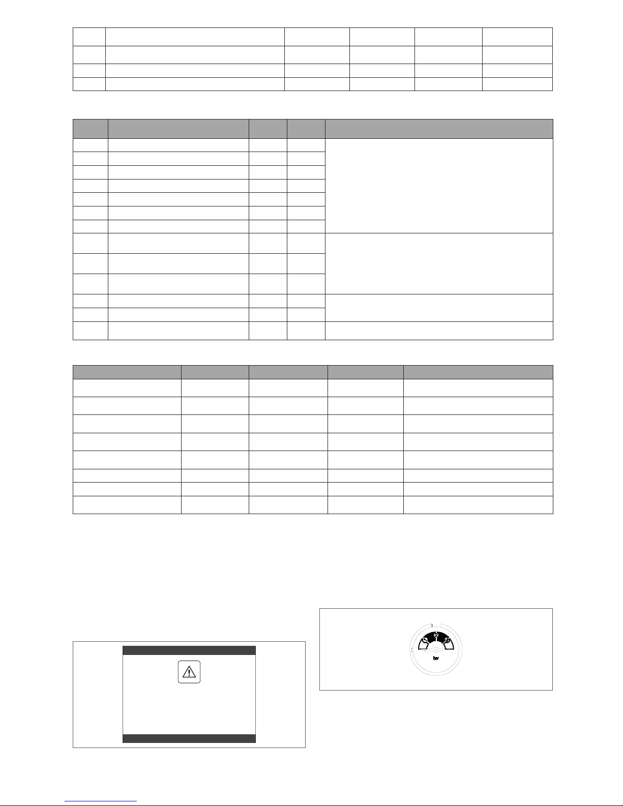
For fault E041
If the pressure drops below the safety threshold of 0.3 bar the
boiler displays the fault code “E041 - WATER TRANSDUCER
LOAD THE SYSTEM” for a transitional time of 10 min during
which it is possible to open the external lling tap until the
pressure is between 1 and 1.5 bar.
E041
WATER TRANSDUCER
LOAD THE SYSTEM
List of combustion faults
ERROR
CODE
ERROR MESSAGE
LED
RED
LED
GREEN
DESCRIPTION OF TYPE OF ALARM
E021 iono alarm ON
These are temporary alarms that if they occur 6 times in an hour they
become denitive; the alarm E097 is displayed and is followed by post-
purging for 45 seconds at the fan’s maximum speed.
It is not possible to release the alarm before the end of the post-purging
unless the boiler’s power supply is switched off.
E022 iono alarm ON
E023 iono alarm ON
E024 iono alarm ON
E067 iono alarm ON
E088 iono alarm ON
E097 iono alarm ON
E085 combustion fault/high CO ON
These are temporary alarms that if they occur 3 times in an hour they
become denitive; the last error to occur is displayed and is followed by a
post-purging of 5 minutes at the fan’s maximum speed.
It is not possible to release the alarm before the end of the post-purging
unless the boiler’s power supply is switched off.
E094 combustion fault/high CO ON
E095 combustion fault/high CO ON
E058 mains voltage fault ON
These are temporary faults that restrict the ignition cycle.
E065 current modulation alarm ON
E086 obstruction fumes alarm ON
Temporary fault reported during the post ventilation. It is maintained a post
ventilation of 5 min at maximum fan speed
Warning lights
BOILER STATUS RED LED GREEN LED RED and GREEN NOTES
Power-on
ashing
0.5 sec. on/0.5 sec. off
The red and green LEDs come on at the same
time
Vent cycle
ashing
0.5 sec. on/1 sec. off
ashing
0.5 sec. on/1 sec. off
The red and green LEDs come sequentially one
at a time
OFF status
ashing
0.3 sec. on/0.5 sec. off
No heat request (stby)
ashing
0.3 sec. on/0.5 sec. off
Transitional ignition/
overtemperature
ashing
0.3 sec. on/0.5 sec. off
Presence of ame ON
Chimney sweep ON Only if the ame is present
Screed heater
ashing
1 sec. on/1 sec. off
ashing
1 sec. on/1 sec. off
The red and green LEDs come on alternately
b
If the pressure drops frequently, contact the Technical
Assistance Centre.
For fault E091
The boiler has an auto-diagnostic system which, based on
the total number of hours in certain operating conditions, can
signal the need to clean the primary heat exchanger. The
intervention of the Technical Assistance Centre is necessary.
-- water pressure low - verify the system pressure
ashing
0.5 sec. on/0.5 off
temporary
-- water pressure high check system
ashing
0.5 sec. on/0.5 off
temporary
-- boiler board communication lost ON temporary
-- BUS 485 communication lost ON temporary
Page 12
12
3.1 HOW TO TOP-UP THE SYSTEM PRESSURE
The system pressure must be checked periodically to ensure
the correct operation of the boiler. The system pressure is
shown at the top of the LCD display or can be read on the
gauge located on the underside of the appliance. When the
boiler is at room temperature, the system pressure should be
approximately 1.0 bar.
If the pressure requires ‘topping-up’ use the following instructions
as a guide.
- Locate the lling valve connections (usually beneath the
boiler, see g. 1).
- Attach the lling loop to both connections.
- Open the lling valve slowly until you hear water entering the
system.
- Close the lling valve when the pressure gauge (on the boiler)
reads between 1 and 1.5 BAR.
- Remove the lling loop from the connections.
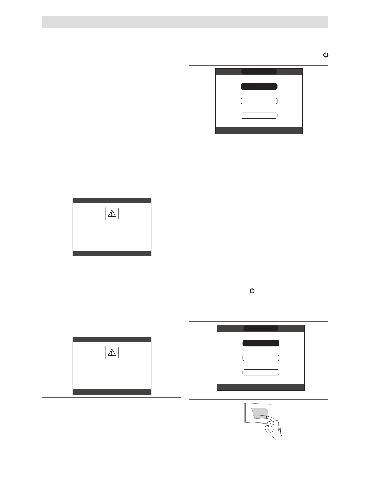
3.2 HOW TO RESET THE APPLIANCE
Reset function
In order to reset the boiler’s operation in the event of a fault,
it is necessary to access the fault description screen. If the
lockout is of a non-volatile type that requires a reset procedure,
this will be indicated on the screen, and can be carried out by
pressing the “ok” button on the REC10.
E020
LIMTIT THERMOSTAT
PRESS OK RESET
At this point, if the correct operating conditions have been
restored, the boiler will restart automatically.
If the attempts to reset the fault do not restore the boiler’s
functionality, please contact your local Customer Support
Service.
Up to a maximum of 3 reset attempts can be made using the
REC10, after which the machine must be disconnected from
the power supply to reset the number of attempts available.
b
Request the intervention of the Technical Assistance
Centre.
E020
LIMIT THERMOSTAT
REC10 ATTEMPTS EXHAUSTED
3. HOW TO...
3.3 HOW TO SHUT DOWN THE SYSTEM FOR
SHORT PERIODS
If necessary the boiler status can be switched to the OFF
position during short periods of absence.
BOILER
OFF
SUMMER
WINTER
Provided that the electrical and gas supplies remain switched
ON to the appliance, the following frost-protection functions
will remain active in order to protect the appliance:
- heating frost-protection: this function is activated if the
temperature measured by the flow sensor drops below 5°C.
A heat request is generated in this phase with the ignition of
the burner at minimum output, which is maintained until the
outlet water temperature reaches 35° C;
- DHW frost-protection: the function starts if the temperature
measured by the DHW sensor falls below 5°C. A heat request
is generated in this phase with the ignition of the burner at
minimum output, which is maintained until the outlet water
temperature reaches 55° C.
b
The activation of the FROST-PROTECTION function
is indicated by a scrolling message at the base of the
REC10 display.
- pump anti-blocking: the circulating pump is energised
for a 30-second period if it remains inactive for more than
24-hours.
3.4 HOW TO SHUT DOWN THE SYSTEM FOR
LONG PERIODS
If the boiler will not be in used for a prolonged period of time,
the following operations must be carried out:
- switch the boiler to OFF
- isolate the appliance from the gas and electricity supplies.
In this case, the frost-protection and anti-blocking systems
are deactivated. Drain both the heating and domestic water
systems to avoid any risk of freezing.
BOILER
OFF
SUMMER
WINTER
ON
OFF
Page 13

13
4.1 WHAT IF I SUSPECT A GAS LEAK
If you suspect a gas leak, turn off the gas supply at the gas
meter and contact your installer or local gas supplier. If you
require further advice please contact your nearest Vokèra ofce.
4.2 WHAT IF I HAVE FREQUENTLY TO TOP-UP
THE SYSTEM
If the system regularly requires topping-up, it may be indicative
of a leak. Please contact your installer and ask him to inspect
the system.
4.3 WHAT IF THE APPLIANCE IS DUE ITS
ANNUAL SERVICE
Advice for tenants only
Your landlord should arrange for servicing.
Advice for homeowners
Please contact Vokèra Customer Service (0844 3910999 (UK)
or 056 7755057 (ROI) if you would prefer a Vokèra service
engineer or agent to service your appliance. Alternatively your
local GAS SAFE registered engineer may be able to service
the appliance for you.
4.4 WHAT IF I NEED TO CALL AN ENGINEER
If you think your boiler may have developed a fault, please contact
your installer or Vokèra Customer Services (0844 3910999 (UK)
or 056 7755057 (ROI) have all your details to hand including
full address and postcode, relevant contact numbers, and your
appliance log book. It is a requirement of your warranty terms
& conditions that your Benchmark logbook has been lled out
correctly and is fully up to date.
4. WHAT IF...
3.5 HOW TO CARE FOR THE APPLIANCE
To clean the outer casing use only a clean damp cloth. Do not
use any scourers or abrasive cleaners.
control
valve
temporary
connection
control
valve
supply pipe
double
check valve
ow/return
pipe
Fig. 1
Page 14

14
All installers are asked to follow the Benchmark Scheme by
adhering to the Code of Practise, which can be obtained from
www.centralheating.co.uk.
The evolve has a new ACC (Active Combustion Control) system.
This new control system ensures functionality, efciency and
low emissions under any conditions.
The ACC system uses an ionisation sensor immersed in the
burner ame, whose information allows the control board to
operate the gas valve that regulates the fuel.
This sophisticated control system provides the auto-regulation
of the combustion, so there is no need for an initial calibration.
The ACC system is able to adapt the boiler to operate with
different gas compositions, different outlet pipes lengths and
different altitudes (within the specied design limits).
The ACC system can also perform an auto-diagnostic operation
that locks out the burner before the permitted upper emission
limit is exceeded.
The comprises a range of high-efciency combination boilers.
These appliances – by design – incorporate electronic ignition,
circulating pump, expansion vessel, safety valve, pressure
gauge and automatic by-pass.
The range is produced as room sealed, category II2H3P
appliances, suitable for internal wall mounting applications only.
Each appliance is provided with a fan powered ue outlet with
an annular co-axial combustion air intake that can be rotated
– horizontally – through 360 degrees for various horizontal or
vertical applications.
These appliances are designed for use with a sealed system
only; consequently they are not intended for use on open
vented systems.
This booklet is an integral part of the appliance. It is therefore
necessary to ensure that the booklet is handed to the person
responsible for the property in which the appliance is located/
installed. A replacement copy can be obtained online from the
Vokera website.
When the product reaches the end of its life it should dismantled
and recycled in accordance with current requirements. Local
authority waste collection facilities may offer such disposal
services.
The boiler complies with basic requirements of the following
Directives:
Gas directive 2009/142/EC;
Yield directive: Article 7(2) and Annex III of directive 92/42/EEC;
Electromagnetic compatibility directive 2014/30/EU;
Low-voltage directive 2014/35/EU;
Directive 2009/125/EC Ecodesign for energy-using appliances;
Directive 2010/30/EU Indication by labelling of the consumption
of energy by energy-related products;
Delegated Regulation (EU) No. 811/2013;
Delegated Regulation (EU) No. 813/2013;
Delegated Regulation (EU) No. 814/2013.
Fig. 2
General layout
1 Analogue pressure gauge
2 Drain valve
3 Diverter valve
4 DHW exchanger
5 Safety valve
6 Pump
7 Lower auto air vent
8 Return sensor
9 Burner
10 Inlet conveyor
11 Fan
12 Mixer
13 Ignition transformer
14 Top ue outlet
15 AAV hose
16 Upper auto air vent
17 Limit thermostat
18 Flow sensor
19 Ignition electrode
20 Detection electrode
21 Expansion vessel
22 Main heat exchanger
23 Pressure transducer
24 Injector
25 Gas valve
26 DHW sensor
27 Siphon
28 Flowmeter
R Heating return connection
F Heating ow connection
G Gas connection
O Hot water outlet
I Cold water inlet
INTRODUCTION
INSTALLATION AND SERVICING INSTRUCTIONS
R F G O I
24C - 28C 32C - 36C
R F G O I
Page 15
15
1.1 PRINCIPLE COMPONENTS
• A fully integrated electronic control board featuring electronic
temperature control, anti-cycle control, pump over-run, selfdiagnostic fault indicator, full air/gas modulation
• Aluminium heat exchanger
• Electronic ignition with ame supervision
• Integral high-head pump
• Fan
• Expansion vessel
• Water owmeter
• Flue sensor
• Pressure transducer
• Safety valve
1.2 MODE OF OPERATION (at rest)
When the appliance is at rest and there are no requests for
heating or hot water, the following functions are active:
• frost-protection system: the frost-protection system protects
the appliance against the risk of frost damage both for CH
and DHW. For CH line, if the main temperature falls to 5°C,
the appliance will function on minimum power until the
temperature on main reaches 35°C.
Moreover if the DHW temperature falls to 5°C, the appliance
will function on minimum power until the temperature on main
reaches 55°C.
• anti-block function: the anti-block function enables the pump
and divertor valve actuator to be energised for short periods,
when the appliance has been inactive for more than 24-hours.
1.3 MODE OF OPERATION (Heating)
When there is a request for heat via the REC/or any external
control, the pump and fan are started, the fan speed will modulate
until the correct signal voltage is received at the control PCB.
At this point an ignition sequence is enabled.
Ignition is sensed by the electronic circuit to ensure ame stability
at the burner. Once successful ignition has been achieved, the
electronic circuitry increases the gas rate to 75% for a period of
15 minutes. Thereafter, the boiler’s output will either be increase
to maximum or modulate to suit the set requirement. When
the appliance reaches the desired temperature the burner will
shut down and the boiler will perform a three-minute anti-cycle
(timer delay).
When the request for heat has been satised the appliance
pump and fan may continue to operate to dissipate any residual
heat within the appliance.
1.4 MODE OF OPERATION (Hot water)
When there is a request for DHW via a hot water outlet or tap,
the pump and fan are started, the fan speed will modulate until
the correct signal voltage is received at the control PCB. At this
point an ignition sequence is enabled.
Ignition is sensed by the electronic circuit to ensure ame
stability at the burner. Once successful ignition has been
achieved, the electronic circuitry increases the gas rate to
maximum or will modulate output to stabilise the temperature.
In the event of the appliance exceeding the desired temperature
(set point) the burner will shut down until the temperature drops.
When the request for DHW has been satised the appliance
pump and fan may continue to operate to dissipate any residual
heat within the appliance.
SECTION 1 - DESIGN PRINCIPLES AND OPERATING SEQUENCE
1.5 SAFETY DEVICES
When the appliance is in use, safe operation is ensured by:
• a pressure transducer that monitors system water pressure
and will de-activate the pump, fan, and burner should the
system water pressure drop below the required minimum
value;
• fan speed sensor to ensure safe operation of the burner;
• a high limit thermostat that over-rides the temperature control
circuit to prevent or interrupt the operation of the burner;
• ame sensor that will shut down the burner when no ame
signal is detected and/or when incomplete combustion or
high emissions are detected;
• ue sensor that will shut down the burner if the ue threshold
temperature is exceeded;
• a safety valve which releases excess pressure from the
primary circuit.
NOTE
When the appliance is rst switched ON or when the electrical
supply is interrupted then restored, the appliance will enter a
short ‘purge’ cycle whereby the pump cycles ON & OFF for
approximately 2-minutes. Only when the ‘purge’ cycle has been
completed, will the appliance go through an ignition sequence.
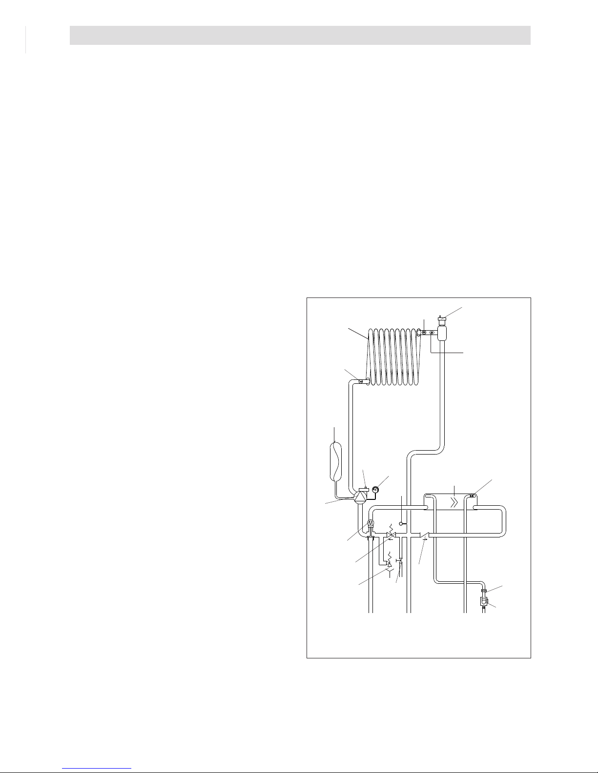
Fig. 3
Expansion
vessel
Pump
Return
temperature
sensor
Main heat
exchanger
Lower
AAV
DHW heat
exchanger
Diverter
valve
Drain
valve
DHW
temperature
sensor
Flow temperature
sensor
Upper AAV
Automatic
by-pass
DHW
non return
valve
CH
return
CH
ow
DHW
inlet
DHW
outlet
Flow restrictor
DHW
owmeter
Analogue
pressure
gauge
Safety
valve
Pressure
transducer
High limit
thermostat
Page 16

16
SECTION 2 - TECHNICAL DATA
2.1 Central Heating evolve 24C evolve 28C evolve 32C evolve 36C
Heat input (kW) 18.00 24.00 30.00 32.00
Maximum heat output (kW) 60/80°C 17.60 23.54 29.37 31.39
Minimum heat output (kW) 60/80°C 3.61 4.19 4.74 4.99
Maximum heat output (kW) 30/50°C 19.17 25.56 31.77 34.08
Minimum heat output (kW) 30/50°C 3.99 4.58 5.26 5.28
Heat input RANGE RATED (Qn) (kW) 18.00 24.00 30.00 32.00
Minimum heat input RANGE RATED (Qm) (kW) 6.70 4.30 4.90 5.10
Minimum working pressure 0.25-0.45 bar
Maximum working pressure 2.5 bar
Minimum ow rate 350 l/h
2.2 Domestic Hot Water
Heat input (kW) 26.00 30.00 34.60 36.00
Flow Rate: ΔT35°C 10.6 12.3 14.2 14.7
Maximum inlet pressure 8 bar
Minimum inlet pressure 0.2 bar
Minimum ow rate 2 l/min
Flow regulator 9 l/min 10 l/min 12 l/min 12 l/min
2.3 Gas Pressures
Inlet pressure (G20) 20.0 mbar 20.0 mbar 20.0 mbar 20.0 mbar
Heating maximum gas rate (m3/hr) 1.90 2.54 3.17 3.38
DHW maximum gas rate (m3/hr) 2.75 3.17 3.66 3.81
Minimum gas rate (m3/hr) 0.39 0.45 0.52 0.54
Injector size (mm) 4.3 4.3 5.2 6.0
2.4 Expansion Vessel
Capacity 8 litres 9 litres
Maximum system volume 74 litres
Pre-charge pressure 1 bar
2.5 Dimensions
Height (mm) 740
Width (mm) 420
Depth (mm) 275 350
Dry weight (kg) 35 36 38 39
2.6 Clearances required for maintenance
Sides 2mm*
Top 100mm** from casing or 25mm above ue elbow (whichever is applicable)**
Bottom 100mm^
Front 450mm^^
* It may be necessary to remove adjacent components if component removal/replacement is required
** Consideration should be given to providing reasonable clearance for the insertion of a FGA probe.
^ This can be reduced to 4mm if a removal panel enables the required 100mm
^^ When installed in a cupboard, this dimension can be reduced to 4mm provided that the required 450mm
is available when the door is opened/removed.
2.7 Connections
Flow & return 22mm
Gas 15mm
DHW hot & cold 15mm
Safety valve 15mm
Condense 21mm
2.8 Electrical
Power consumption CH (Watts) 54 65 79 93
Power consumption DHW (Watts) 86 89 94 103
Voltage (V/Hz) 230/50
Internal fuse 4 A T (for PCB) - 3.15A F (for connections block)
External fuse 3A
2.9 Flue Details (concentric 60-100)
Maximum horizontal ue length (60/100mm) 10.0 m 10.0 m 8.0 m 6.0 m
Maximum vertical ue length (60/100mm) 11.0 m 11.0 m 9.0 m 7.0 m
2.10Efciency
SEDBUK (%) 90.16 90.30 90.21 90.30
2.11 Emissions
CO2 @ maximum output (%) (*) 9.2 9.0 9.0 9.0
CO2 @ minimum output (%) (*) 9.1 8.9 9.1 8.8
CO @ maximum output (ppm) 140 150 220 160
CO @ minimum output (ppm) 10 10 20 20
NOx rating class 6 class 6 class 6 class 6
Page 17
17
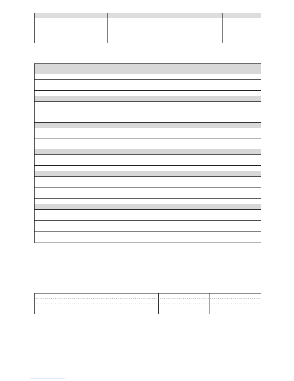
NOTE (if the outdoor temperature sensor or the control panel, or even both devices, are present in the boiler)
With reference to the Delegated Regulation (EU) No. 811/2013, the information in the table can be used for completing the product
data sheet and the labelling for room heating appliances, for mixed heating appliances, for all those appliances for enclosed space
heating, for temperature control devices and solar devices:
NOTE NOTE NOTE
OUTDOOR TEMPERATURE SENSOR II 2%
CONTROL PANEL* V 3%
OUTDOOR TEMPERATURE SENSOR + CONTROL PANEL* VI 4%
(*) Set as ambient regulator
(*) CO2 tolerance= +0.6% -1%
2.12 Fan rotations
Number of fan rotations with slow ignition (rpm) 5,500 5,500 5,000 5,000
Maximum number of heating fan rotations (rpm) 5,600 6,500 6,900 7,500
Minimum number of heating fan rotations (rpm) 1,500 1,500 1,500 1,500
Maximum number of DHW fan rotations (rpm) 7,900 7,900 7,800 8,100
Minimum number of DHW fan rotations (rpm) 1,500 1,500 1,500 1,500
Parameter Symbol evolve
24C
evolve
28C
evolve
32C
evolve
36C
Unit
Seasonal space heating energy efciency class - A A A A Water heating energy efciency class - A A A A -
Rated heat output Pnominal 18 24 29 31 kW
Seasonal space heating energy efciency ηs 94 94 94 94 %
Useful heat output
At rated heat output and high-temperature
regime (*) P4 17.6 23.5 29.4 31.4 kW
At 30% of rated heat output and low-temperature
regime (**) P1 5.9 7.9 9.8 10.5 kW
Useful efciency
At rated heat output and high-temperature
regime (*) η4 88.2 88.3 88.1 88.2 %
At 30% of rated heat output and low-temperature
regime (**) η1 98.9 98.9 98.6 98.6 %
Auxiliary electricity consumption
At full load elmax 28.0 37.0 40.0 31.4 W
At part load elmin 14.0 14.0 14.0 10.5 W
In Stand-by mode PSB 3.0 3.0 3.0 3.0 W
Other parameters
Stand-by heat loss Pstby 42.0 42.0 37.0 46.0 W
Pilot ame energy consumption Pign - - - - W
Annual energy consumption QHE 37 42 52 56 GJ
Sound power level, indoors LWA 51 53 54 52 dB
Emissions of nitrogen oxides NOx 46 33 41 48 mg/kWh
For combination heaters
Declared load prole XL XL XXL XXL
Water heating energy efciency ηwh 87 87 85 86 %
Daily electricity consumption Qelec 0.152 0.148 0.165 0.159 kWh
Daily fuel consumption Qfuel 22.216 22.411 28.358 28.227 kWh
Annual electricity consumption AEC 33 32 36 35 kWh
Annual fuel consumption AFC 17 17 22 22 GJ
(*) High-temperature regime means 60 °C return temperature at heater inlet and 80 °C feed temperature at heater outlet.
(**) Low temperature means for condensing boilers 30 °C, for low-temperature boilers 37 °C and for other heaters 50 °C
return temperature (at heater inlet).
Page 18
18
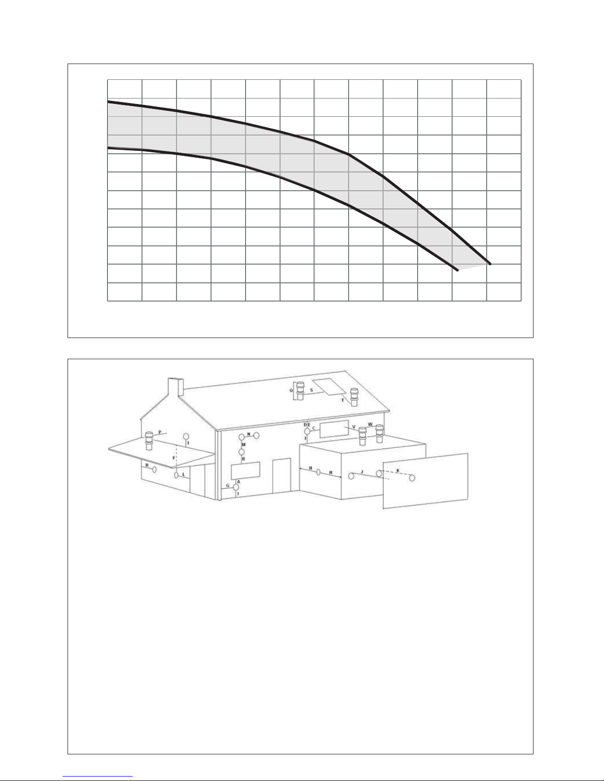
Key Location Minimum distance
A Below an opening (window, air-brick, etc.) 300 mm
B Above an opening (window, air-brick, etc.) 300 mm
C To the side of an opening (window, air-brick, etc.) 300 mm
D Below gutter, drain-pipe, etc. 25 mm
E Below eaves 25 mm
F Below balcony, car-port roof, etc. 25 mm
G To the side of a soil/drain-pipe, etc. 25 mm (60mm for 80/125mm)
H From internal/external corner 25 mm (60mm for 80/125mm)
I Above ground, roof, or balcony level 300 mm
J From a surface or boundary facing the terminal 600 mm*
K From a terminal facing a terminal 1200 mm
L From an opening in the car-port into the building 1200 mm
M Vertically from a terminal on the same wall 1500 mm
N Horizontally from a terminal on the same wall 300 mm
P From a structure to the side of the vertical terminal 300 mm
Q From the top of the vertical terminal to the roof ashing As determined by the xed collar
of the vertical terminal
R To the side of a boundary 300 mm
S To the side of an opening or window on a pitched roof 600 mm
T Below an opening or window on a pitched roof 2000 mm
V From a vertical terminal to an adjacent opening (window, air-brick, etc.) (call Vokera technical for advice)
W From a vertical terminal to an adjacent vertical terminal 300 mm (only if both terminals are the same height)
Fig. 4
2.13 PUMP DUTY
Fig. 4 shows the ow-rate available – after allowing for pressure loss through the appliance – for system requirements. When
using this graph, apply only the pressure loss of the system.
Flow rate (l/h)
Residual head (mbar)
0
50
100
150
200
250
300
350
400
450
500
550
600
0 1 00 200 300 400 500 600 700 800 900 10 00 1100 12 00
Fig. 5
*The possibility that this may be deemed as causing a nuisance, should be considered
Page 19
19
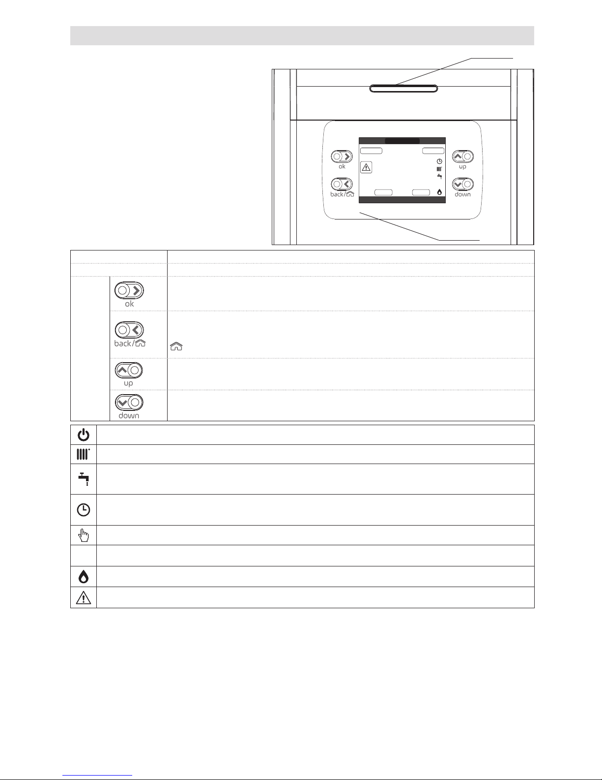
The REC10 is a fully functional UI (User Interface)
that acts as a visual reference for the appliance and
system status; and can also be used to view, input
and adjust relevant system parameters and functions.
The centre of the UI will normally display the current
operating temperature (according to the mode of
operation); however when the screensaver is active,
the current time will be displayed.
The value expressed in bar refers to the system’s
water pressure.
The top of the screen shows the information regarding
the current date and time, as well as the outdoor
temperature, if available.
On the left and right sides are displayed the icons
indicating the status of the system; their meaning is
as follows.
FRI
18/05/2013 12:17
MENU
INFO SET
PLANT
HOT WATER TEMPERATURE
STATE
42
°C
P
1.3
bar
LED
REC10
SECTION 3 - CONTROL PANEL (REC10)
This icon indicates that the OFF operating status mode has been set. Any ignition request is ignored except for the frost-protection function.
The pump anti-lock, 3-way valve and frost protection functions remain active.
This icon indicates that WINTER mode has been selected (HEATING function enabled). If a heating request from the main zone is in progress, the icon will be flashing.
This icon indicates that the circuit for domestic hot water production is enabled. When a domestic hot water request is in progress, the icon
flashes. The P at the top of the domestic hot water icon indicates that the boiler preheating function is enabled; the P when flashing indicates
that a preheating request is in progress.
When the “embedded clock ” is enabled this icon indicates that the system heating (main zone) is in AUTOMATIC mode (the management
of the heating requests follows the ON/OFF times that have been programmed).
If the heating function is not enabled during the current time frame, the icon will be crossed out.
When the “central heating programming timing” is enabled this icon indicates that the system heating (main zone) is in MANUAL mode (the
management of the heating requests does not follow what has been set with the programming timing, but it is always active).
OFF This icon indicates that the system (main zone) has been set to off (not active).
This icon indicates that the system is detecting the presence of a flame.
This icon indicates the presence of an anomaly, and is always flashing.
Pressing the keys
“up” and “down”
it is possible to choose
from among the following options:
• PLANT: the display will indicate the temperature of the
domestic hot water sensor rather than the flow sensor of
the boiler
• STATE/BOILER: enables access to choose the operating
mode of the appliance: OFF, Summer, Winter
• STATE/MAIN ZONE (if embedded clock disabled): enables
access to choose the operating mode (On or OFF) of the
main heating zone
• STATE/MAIN ZONE (if embedded clock is enabled):
enables access to choose operating mode of the embedded
clock (AUTO, MANUAL, OFF)
• SET: to view or adjust the heating or hot water setpoint
value or to enable or disable preheating
• INFO: to view the current values or status of the various
appliance inputs/sensors
• MENU: to access the system’s configuration menus
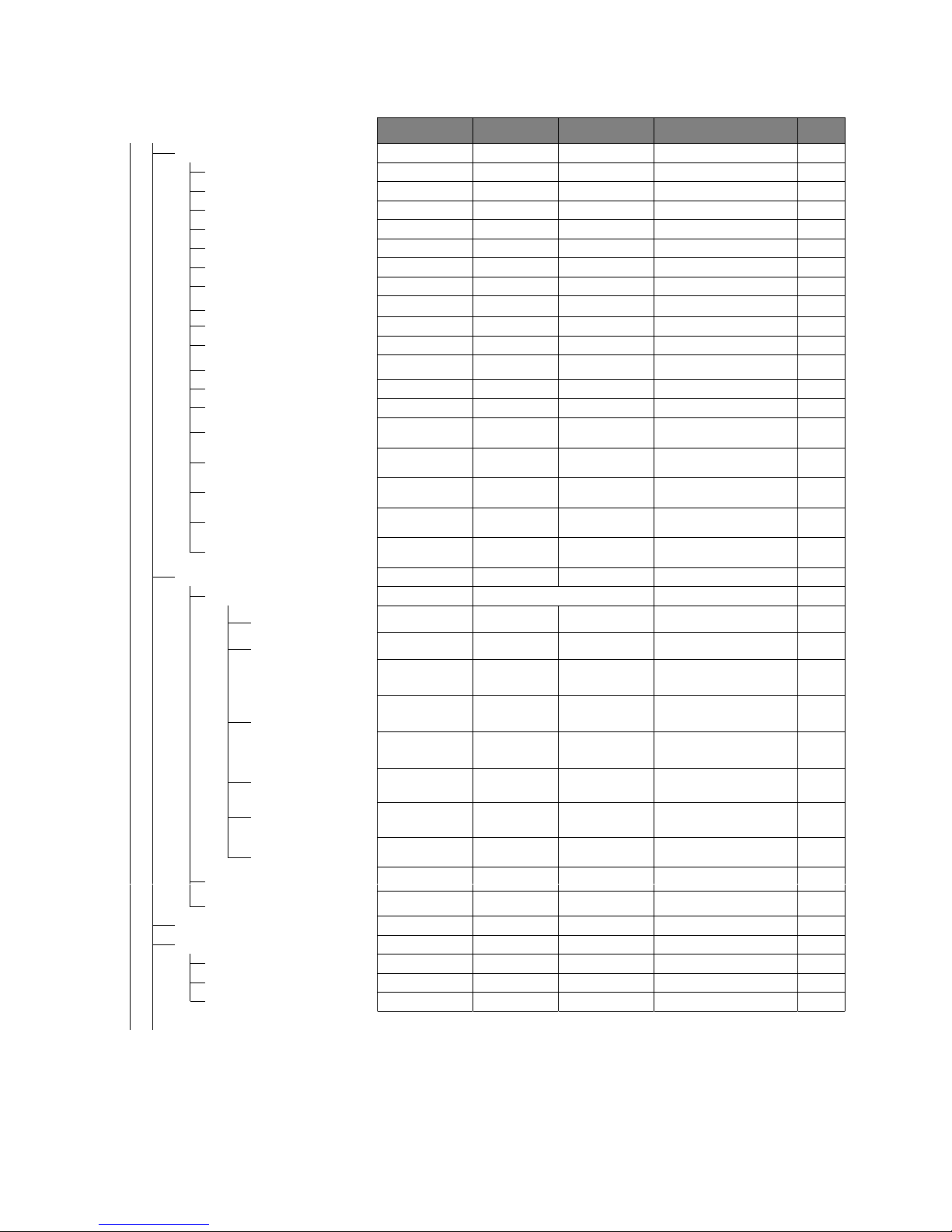
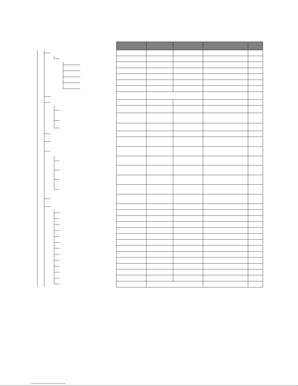
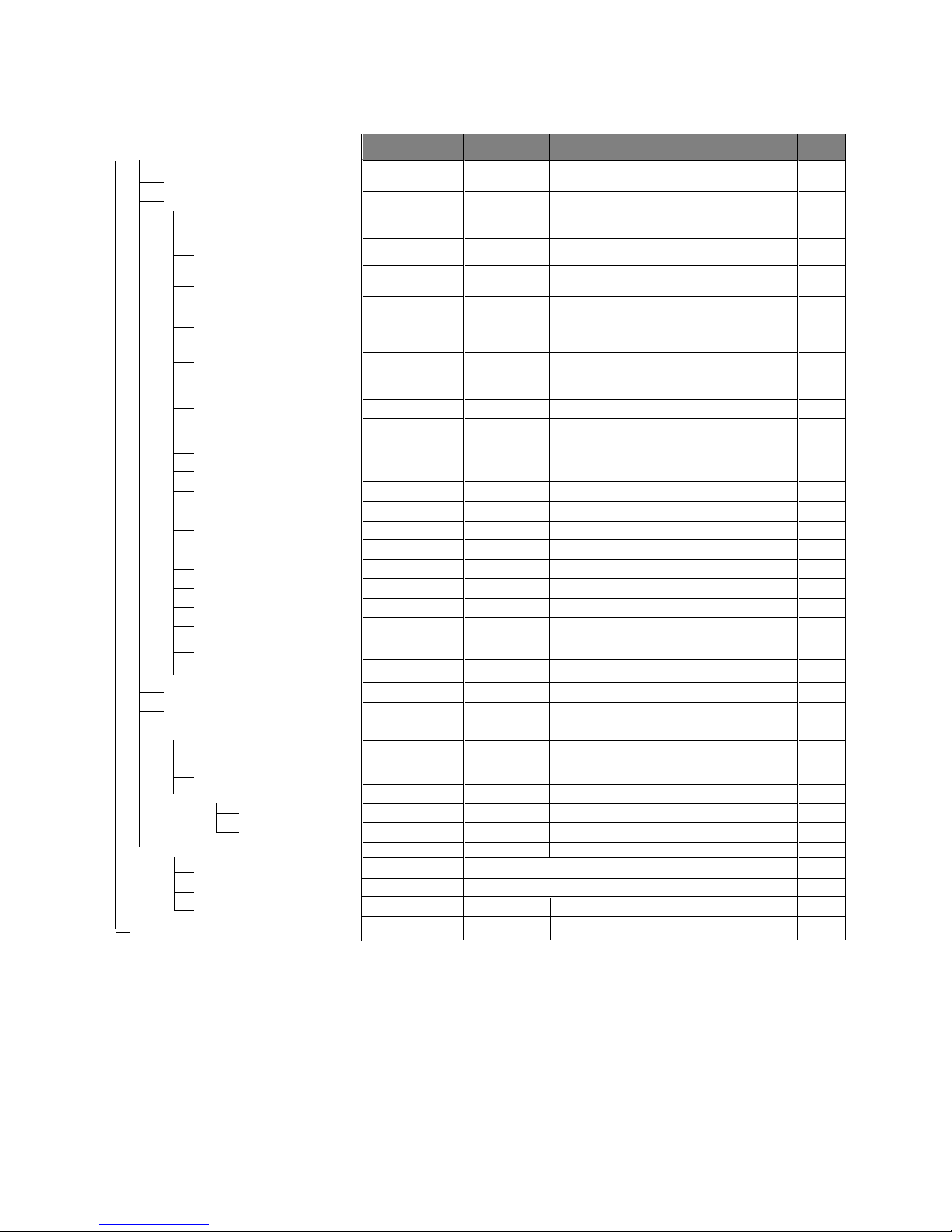
The configuration MENU is organised with a multi-access
level tree structure. With the “ok” key you can access the
selected submenu, with the
“up” and “down”
keys it is
possible to navigate through the submenus, while the “back”
key takes you back to the previous level.
An access level has been fixed for each submenu: USER level,
always available; TECHNICAL level, password protected.
Below is a summary of the MENU tree structure of the REC10.
b
Some of the information might not be available on the
REC10 depending on the access level, the status of the
machine or the system conguration.
LED
Light signal indicating the operating status of the boiler. Can be red or green (see specific paragraph)
REC10
Boiler control panel
Key area
ok= confirm
back= ret
urn to the previous screen
cancel selection
return to the main screen (press > 2 sec.)
up= allows you to choose between the options PLANT-STATE-SET-INFO-MENU and to
surf through the
submenus
scrolling upwards
down= allows you to choose between the options PLANT-STATE-SET-INFO-MENU and to
surfe through the
submenus
scrolling down
Page 20

20
MENU
DEFAULT VALUE
MINIMUM
VALUE
MAXIMUM
VALUE
ACCESS LEVEL
NOTES
SET
VALUE
SETTINGS
USER
TIME & DATE
USER
LANGUAGE
ITALIANO / ENGLISH USER
BACKLIGHT
5 min 1 min 15 min USER
TIME SCHEDULE
USER
MAIN
USER
Only if POR = 1
ZONE1
USER
Only if POR = 1
ZONE2
USER
Only if POR = 1
DHW
USER
DHW HEAT PUMP
USER
TECHNICAL
INSTALLER
INSTALLATION
INSTALLER
ZONES MANAGER
INSTALLER
MODIFY ZONE MAIN MAIN / ZONE1 / ZO NE2 INSTALLER
ACTUATION TYPE
ITRF05/AKM ITRF05/AK M BE16
INSTALLER
Only MAIN zo ne
REQUEST TYPE THERMOSTAT
THERMOSTAT / TEMPERATURE PROBE /
REC10 MASTER / REC10 SLAVE
INSTALLER
BE16 ADDRESS - - 1 6
INSTALLER
Only zones wit h
ACTUATION = BE16
HYDRAULIC CONF DIRECT ZONE DIRECT ZONE MIXING ZONE
INSTALLER
Only zones wit h ACTUATION = BE16
ZONE TYPE HIGH TEMP. HIGH TEMP . LOW TEMP. INSTALLER
MIN CH SET
40°C (AT)
20°C (BT)
20°C MAX CH SET INSTALLER
MAX CH SET
80,5°C (AT)
45°C (BT)
MIN CH SET
80,5°C (AT)
45°C
(BT)
INSTALLER
CHANGE NAME
INSTALLER
PI - PROPORTIONAL 5 0 99
SERVICE
Only mixing z ones with A
CTUATION=BE16
PI - INTEGRAL 10 0 99
SERVICE
Only mixing z ones with ACTUATION=BE 16
VALVE RUN 120 s ec 0 sec 240 s ec
SERVICE
Only mixing z ones with ACTUATION=BE 16
CLOSING AT POWE R ON 140 sec 0 sec 240 sec
SERVICE
Only mixing z ones with ACTUATION=BE 16
OUTLET OVER 55°C 0°C 100°C
SERVICE
Only BT zones with A CTUATION =BE16
OUTLET OVER TEST TIME 0min 0min 240min
SERVICE
Only BT zones with A CTUATION =BE16
OUTLET OVER WAIT TIME 2min VALVE RUN 240min
SERVICE
Only BT zones with A CTUATION =BE16
OUTLET OVER REST TIME 2min 0min 24 0min
SERVICE
Only
BT zones with ACT UATION =BE16
FREEZE PROT TEMP 6°C -20°C 50°C
SERVICE
Only zones wit h ACTUATION = BE16
FREEZE PROT OFFSET ZONE 5°C 1°C 20°C
SERVICE
Only zones wit h ACTUATION = BE16
FREEZE PROT T EXT 10°C 0°C 100°C
SERVICE
Only zones wit h ACTUATION = BE16
POR
0 (1 if REC10
in the AMBIENT)
0 1 INSTALLER
ADD ZONE
INSTALLER
DELETE ZONE
INSTALLER
SENSOR CALIBRATION 0,0°C - 6,0°C 6,0°C INSTALLER
SYSTEM RESET
INSTALLER
FACTORY SET
Page 21
21
MINIMUM
VALUE
MAXIMUM
VALUE
ACCESS LEVEL
NOTES
SET
VALUE
PARAMETERS
INSTALLER
TIMER OFF CH 3 m in 0 m in 20 min INSTALLER
HYST ON HIGH TEMP 5°C 2°C 10 °C SERVICE
HYST OFF HIGH TEMP 5°C 2°C 10°C SERVICE
HYST ON LOW TEMP 3°C 2°C 10°C SERVICE
HYST OFF LOW TEMP
3°C 2°C 10°C SERVICE
SP INCR HIGH TEMP
5°C 0°C 10°C SERVICE
SP INCR LOW TEMP
0°C 0°C 6°C SERVICE
INCR COOLING SP
0°C 0°C 10°C SERVICE
PUMP DUTY CYCLE
85 41 100 SERVICE
RESET TIMERS CH
FUNC. NOT ACTIVE FUNC. NOT ACT IVE FUNCTION A CTIVE INSTALLER
DHW THERMOSTAT
RELATED RELATED ABSOLUTE
INSTALLER
Only in insta ntaneous configuration
SLIDING OUTLE T
DEACTIVATE FUNC. DEACTIVATE FUNC. AC TIVATE FUNCTION
INSTALLER
CH DELAY POST-DHW
0 0 1 SERVICE
CH DELAY TIME
6sec 1sec 255sec
SERVICE
If CH DELAY POST-DHW = 1
PRESS TRANSDUCE R
1 0 1 SERVICE
LOAD ENABLE
0 0 1
SERVICE
Only if PRESS TRANSDUCER = 1
START LOADING VALUE
0,6 0,4 1
SERVICE
Only if LOAD ENABLE = 1
PREHEATING
0 0 1
INSTALLER
Only if managed by the c ontrol board
THERMOREGULATI ON
INSTALLER
CLIMATIC CURVES
MAIN MAIN / ZONE1 / ZONE2 INSTALLER
FIXED SET POINT
80,5 °C (AT)
45 °C (BT)
MIN CH SET MAX CH SET
INSTALLER
If EXTERNAL PROBE NOT connected
NIGHT COMP FUNC. NOT ACTIV E FUNC. NOT A CTIVE FUNCTI ON ACTIVE
INSTALLER
If EXTERNAL PROBE connected
CURVE SLOPE
2,0 1,0 3,0
INSTALLER
If EXTERNAL PROBE connected,
request type
TA
and zone type
AT
0,4 0,2 0,8
INSTALLER
If EXTERNAL PROBE connected,
request type TA and zone ty pe
BT
2,0 0,1 5,0
INSTALLER
If request type AMBIENT PROBE
or REC10
AMBIENT INFLUE NCE 10 0 20
INSTALLER
If request type AMBIENT PROBE
or REC10
OFFSET 20°C 20°C 40 °C
INSTALLER
If request type AMBIENT PROBE
or REC10
COOLING
18°C 4°C 20°C INSTALLER
BUILDING TYPE
5min 5min 20min
INSTALLER
Only i
f EXTERNAL PROBE connected
OUTDOOR REACTIV ITY
20 0 255
INSTALLER
Only i
f EXTERNAL PROBE connected
RANGE RATED
MAX CH MIN MAX CH INSTALLER
CALIBRATION
INSTALLER
MIN
INSTALLER
MAX
INSTALLER
MIN MAX INSTALLER
MAX CH
DEFAULT VALUE
FACTORY SET
see MULTIGAS TABLE
see MULTIGAS TABLE
see MULTIGAS TABLE
1500 RPM
3000 RPM
9999 RPM5500 RPM
Page 22
22
MINIMUM
VALUE
MAXIMUM
VALUE
ACCESS LEVEL
NOTES
SET
VALUE
SWEEPER
INSTALLER
ACTIVATE FUNCTION
INSTALLER
DEACTIVATE FUNCTION
INSTALLER
MAX SPEED MAX
INSTALLER
RANGE RATED SPEED RANGE RATED
INSTALLER
MIN SPEED MIN
INSTALLER
CHANGE FAN SPEED Current speed MIN MAX INSTALLER
ANTI-LEGIONEL LA
WEEKLY FUNCTION
F. NOT ACTIVE / DAILY FUNCTION /
WEEKLY FUNCTION
INSTALLER
VENT CYCLE
ENABLE FUN. ENABLE FUN. DISABLE FUN. SERVICE
DISABLE FUNCTION
SERVICE
ENABLE FUNCTION
SERVICE
STOP FUNCTION
INSTALLER
Only if VENT CYLCE in pro gress
EXHAUST PROBE RESET
INSTALLER
ADD WATER TANK
INSTALLER
Only in insta ntaneous configuration
WATER TANK
INSTALLER
REMOVE WATER TANK
INSTALLER
WATER TANK SETPOINT
50°C 37,5°C 60°C
INSTALLER
Only if HEAT P UMP enabled to DHW
TANK FROST PROTE CT
7°C 0°C 100°C
SERVICE
Only if HEAT P UMP enabled to DHW
TANK FR PROT OFFSET
5°C 1°C 20°C
SERVICE
Only if HEAT P UMP enabled to DHW
ADD SOLAR PLANT
INSTALLER
Only if solar system is not c onfigured
SOLAR
INSTALLER
REMOVE SOLAR PLANT
INSTALLER
T MAX TANK 60°C 10°C 130°C INSTALLER
DELTA T ON PUMP 8°C DELTA T OFF 30 °C INSTALLER
DELTA T OFF PUMP 4°C 4°C DELTA T ON INSTALLER
INTEGRATION DELAY 0 min 0 min 199 mi n INSTALLER
COLLECTOR T MIN (- -) (- -) / -30°C 0°C INSTALLER
COLLECTOR T MAX 110°C COLL. T PROT 180°C INSTALLER
COLLECTOR T PROT 110°C 80°C. T MAX COLL. INSTALLER
COLLECTOR T AUTH 40°C T LOCK 95°C INSTALLER
COLLECTOR T LOCK 35 °C -20°C COLL. T AUTH INSTALLER
PWM COLL PUMP 0 min 0 min 30 min INSTALLER
TANK COOLING FUNC. NOT ACTIVE FUNC. NOT ACTIVE FUNCTION A CTIVE INSTALLER
SOLAR PUMP STATE OFF OFF / ON / AUTO INSTALLER
DEFAULT VALUE
FACTORY SET
Page 23
23
MINIMUM
VALUE
MAXIMUM
VALUE
ACCESS LEVEL
NOTES
SET
VALUE
ADD HEAT PUMP
INSTALLER
Only if heat pump not configured
HEAT PUMP
INSTALLER
REMOVE HEAT PUMP
INSTALLER
Only if heat pump configure d
USE FREE CONTACTS / USE BUS USE BUS USE BUS USE FREE CONTACTS SERVICE
ENABLE / DISABLE COOLING DEACTIVATE FUNCTION FUNCTION ACTIVE DEACTIVATE FUNCTION INSTALLER
USE FOR DHW / DON'T USE FOR DHW
DHW FUNCTION
NOT ACTIVE
DHW FUNCTION
ACTIVE
DHW FUNCTION
NOT ACTIVE
INSTALLER
ANTI FREEZE DELTA SET 1°C 0°C 6°C SERVICE
ENABLE / DISABLE NIGHT REDUCT DEACTIVATE FUNCTION FUNCTION A CTIVE DEACTIVATE FUNCTION INSTALLER
REDUCED FREQUE NCY 100% 50% 100% SERVICE
MIN OUTDOOR TEM P 5°C -5°C 20°C INSTALLER
MIN DHW OUT TEMP 5°C -5°C 20°C INSTALLER
MIN EMERG OUT T -10°C -20°C 10°C INSTALLER
BOILER INTEGR DELAY
30min
1min
240min
SERVICE
HP INTEGR DELAY
30min
1min
240min
SERVICE
BOILER WAITING
2min
1min
60min
SERVICE
HEAT PUMP WAITING
2min
1min
60min
SERVICE
INTEGRATION OFFSET
5°C
0°C
10°C
SERVICE
WINTER SUMMER DE LAY
0h
0h
24h
SERVICE
WARNING VALIDATION
60sec
1sec
300sec
SERVICE
ENABLE CIRC STATE ON/ AUTO
AUTO
ON
AUTO
INSTALLER
DHW HP SETPOINT
60°C
20°C
60°C
SERVICE
DHW OFFSET
10°C
0°C
25°C
SERVICE
ENABLE ALARM HISTORY
SERVICE
ALARM HISTORY
INSTALLER
SCREED HEATING
DEACTIVATE F.
DEACTIVATE F.
ACTIVATE F.
INSTALLER
DEACTIVATE FUNCTION
INSTALLER
ACTIVATE FUNCTION
INSTALLER
FUNCTION SETTIN GS
SERVICE
TFMIN
20°C
15°C
30°C
SERVICE
TFMAX
35°C
30°C
55°C
SERVICE
SYSTEM INFO
SERVICE
DEFAULT VALUE
FACTORY SET
COMBUSTION MONITORING
GAS TYPE
COMBUSTION OFFSET
BOILER TYPE
NG
NG/LPG
SERVICE
SERVICE
SERVICE
SERVICE
A
A/B/C
RESTORE
RESTORE
RESET
Page 24
24
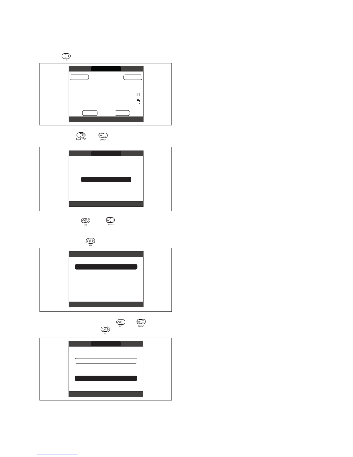
3.1 Access to the technical parameters
Through the REC10 it is possible to access, using the
TECHNICAL menu, a series of parameters that can be
programmed to allow you to personalise the operation of the
boiler:
- select MENU on the initial page of the REC10 and press
the key
18/05/2013 12:17
INFO SET
30
°C
.3
MENU
FRI
STATE
PLANT
HOT WATER TEMPERATURE
1.3
bar
- keep the keys
and
pressed at the same time to
enter the
password menu (about 5 sec)
18/11/2013 12:17
FRI
SETTINGS
MENU
SELECT OPTION
- using the keys and select the value of the
password to
access the INSTALLER or SERVICE
authorisation level, depending on the level of the tree menu,
then press the key
00
INSERT PASSWORD
- select TECHNICAL with the keys and , confirming
the selection with the key
SETTINGS
TECHNICAL
SELECT OPTION
MENU
- access the desired menu and change/view the parameter
concerned (see the menu tree on page 20).
It is possible to return to the start page at any time by keeping
the key “back” pressed for at least 2 seconds.
Page 25

25
SECTION 4 - GENERAL REQUIREMENTS (UK)
This appliance must be installed by a competent person
in accordance with the Gas Safety (Installation & Use)
Regulations.
4.1 RELATED DOCUMENTS
The installation of this boiler must be in accordance with the
relevant requirements of the Gas Safety (Installation & Use)
Regulations, the local building regulations, the current I.E.E.
wiring regulations, the bylaws of the local water undertaking,
the Building Standards (Scotland) Regulation, and Building
Standards (Northern Ireland) Regulations.
It should be in accordance also with any relevant requirements
of the local authority and the relevant recommendations of the
following British Standard Codes of Practice.
4.2 LOCATION OF APPLIANCE
The appliance may be installed in any room or internal space,
although particular attention is drawn to the requirements
of the current I.E.E. wiring regulations, and in Scotland, the
electrical provisions of the Building Regulations, with respect
to the installation of the appliance in a room or internal space
containing a bath or shower.
When an appliance is installed in a room or internal space
containing a bath or shower, the appliance or any control
pertaining to it must not be within reach of a person using the
bath or shower (refer to IEE regs).
The location chosen for the appliance must permit the provision
of a safe and satisfactory ue and termination. The location
must also permit an adequate air supply for combustion
purposes and an adequate space for servicing and air
circulation around the appliance. Where the installation of the
appliance will be in an unusual location special procedures
may be necessary, BS 6798 gives detailed guidance on this
aspect.
A compartment used to enclose the appliance must be
designed and constructed specically for this purpose. An
existing compartment/cupboard may be utilised provided that
it is modied to suit.
Details of essential features of compartment/cupboard design
including airing cupboard installations are given in BS 6798.
This appliance is not congured for external installation
applications.
4.3 GAS SUPPLY
The gas meter – as supplied by the gas supplier – must be
checked to ensure that it is of adequate size to deal with
the maximum rated input of all the appliances that it serves.
Installation pipes must be tted in accordance with BS 6891.
Pipe work from the meter to the appliance must be of adequate
size. Pipes of a smaller size than the appliance gas inlet
connection must not be used. The installation must be tested
for soundness in accordance with BS6891.
If the gas supply serves more than one appliance, it must
be ensured that an adequate supply is maintained to each
appliance when they are in use at the same time.
NOTE
It is recognised that ‘pressure loss’ through the gas cock and
gas valve may result in a pressure drop of approximately
2mbar between the gas meter and gas valve inlet test
point; this will not impair the performance of the appliance,
provided that a dynamic pressure of 18mbar is available at
the appliance inlet.
4.4 FLUE SYSTEM
The terminal should be located where the dispersal of combustion
products is not impeded and with due regard for the damage
and discoloration that may occur to building products located
nearby. The terminal must not be located in a place where it is
likely to cause a nuisance (see g. 5).
In cold and/or humid weather, water vapour will condense
on leaving the terminal; the effect of such pluming must be
considered.
If installed less than 2m above a pavement or platform to which
people have access (including balconies or at roofs) the terminal
must be protected by a guard of durable material. The guard
must be tted centrally over the terminal. Refer to BS 5440
Part 1, when the terminal is 0.5 metres (or less) below plastic
guttering or 1 metre (or less) below painted eaves.
4.5 AIR SUPPLY
The following notes are intended for general guidance only. This
appliance is a room-sealed, fan-ued boiler, consequently it
does not require a permanent air vent for combustion air supply.
When installed in a cupboard or compartment, ventilation for
cooling purposes is also not required.
4.6 WATER CIRCULATION
Detailed recommendations are given in BS 5449 Part 1 and
BS 6798. The following notes are for general guidance only.
4.6.1 PIPEWORK
It is recommended that copper tubing to BS 2871 Part 1 is used
in conjunction with soldered capillary joints. Where possible
pipes should have a gradient to ensure air is carried naturally to
air release points and that water ows naturally to drain cocks.
Except where providing useful heat, pipes should be insulated
to avoid heat loss and in particular to avoid the possibility of
freezing. Particular attention should be paid to pipes passing
through ventilated areas such as under oors, loft space, and
void areas.
4.6.2 AUTOMATIC BY-PASS
The appliance has a built-in automatic by-pass, consequently
there is no requirement for an external by-pass, however the
design of the system should be such that it prevents boiler
‘cycling’.
4.6.3 DRAIN COCKS
These must be located in accessible positions to facilitate
draining of the appliance and all water pipes connected to the
appliance. The drain cocks must be manufactured in accordance
with BS 2879.
4.6.4 AIR RELEASE POINTS
These must be positioned at the highest points in the system
where air is likely to be trapped. They should be used to expel
trapped air and allow complete lling of the system.
4.6.5 EXPANSION VESSEL
The appliance has an integral expansion vessel to accommodate
the increased volume of water when the system is heated.
Refer to the specication table for more detailed information.
4.6.6 FILLING POINT
A method for initial lling of the system and replacing water lost
during servicing etc. directly from the mains supply, is provided
(see g. 6). This method of lling complies with the current
Water Supply (Water Fittings) Regulations 1999 and Water
Bylaws 2000 (Scotland).
4.6.7 LOW PRESSURE SEALED SYSTEM
An alternative method of lling the system would be from an
independent make-up vessel or tank mounted in a position at
least 1 metre above the highest point in the system and at least
5 metres above the boiler (see g. 7).
The cold feed from the make-up vessel or tank must be tted
with an approved non-return valve and stopcock for isolation
purposes. The feed pipe should be connected to the return pipe
as close to the boiler as possible.
BS 5440 PART 1 FLUES
BS 5440 PART 2 FLUES & VENTILATION
BS 5449 PART 1 FORCED CIRCULATION HOT WATER SYSTEMS
BS 5546 INSTALLATION OF GAS HOT WATER SUPPLIES FOR DOMESTIC PURPOSES
BS 6798 INSTALLATION OF BOILERS OF RATED INPUT NOT EXCEEDING 70kW
BS 6891 LOW PRESSURE INSTALLATION PIPES
Page 26
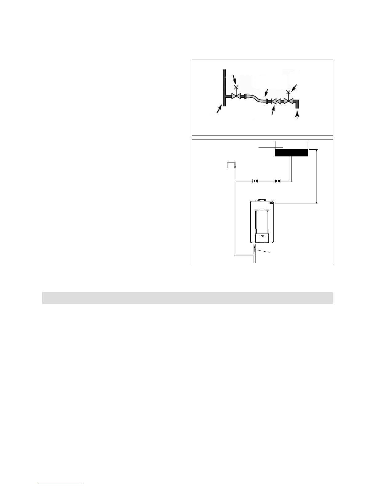
26
ow/return
pipe
control
valve
temporary
connection
control
valve
supply
pipe
double
check valve
Make-up vessel
or tank
Automatic
air-vent
Non-return
valve
Stopcock
5.0 metres minimum
Heating
return
This appliance must be installed by a competent person in
accordance with and dened by, the Standard Specication
(Domestic Gas Installations) Declaration (I.S. 813).
4A.1 RELATED DOCUMENTS
The installation of this boiler must be in accordance with the
relevant requirements of the local building regulations, the
current ETCI National Rules for Electrical Installations, and the
bylaws of the local water undertaking.
It should be in accordance also with any relevant requirements
of the local and/or district authority.
4A.2 LOCATION OF APPLIANCE
The appliance may be installed in any room or internal space,
although particular attention is drawn to the requirements of
the current ETCI National Rules for Electrical Installations, and
I.S. 813, Annex K.
When an appliance is installed in a room or internal space
containing a bath or shower, the appliance or any control
pertaining to it must not be within reach of a person using the
bath or shower.
The location chosen for the appliance must permit the provision
of a safe and satisfactory ue and termination. The location must
also permit an adequate air supply for combustion purposes
and an adequate space for servicing and air circulation around
the appliance. Where the installation of the appliance will be
in an unusual location special procedures may be necessary,
refer to I.S. 813 for detailed guidance on this aspect.
SECTION 4A - GENERAL REQUIREMENTS (EIRE)
A compartment used to enclose the appliance must be
designed and constructed specically for this purpose. An
existing compartment/cupboard may be utilised provided that
it is modied to suit.
This appliance is not congured for external installation.
4A.3 GAS SUPPLY
The gas meter – as supplied by the gas supplier – must be
checked to ensure that it is of adequate size to deal with
the maximum rated input of all the appliances that it serves.
Installation pipes must be tted in accordance with I.S. 813.
Pipe work from the meter to the appliance must be of adequate
size. Pipes of a smaller size than the appliance gas inlet
connection must not be used. The installation must be tested
for soundness in accordance with I.S. 813.
If the gas supply serves more than one appliance, it must
be ensured that an adequate supply is maintained to each
appliance when they are in use at the same time.
NOTE
It is recognised that ‘pressure loss’ through the gas cock and
gas valve may result in a pressure drop of approximately
2mbar between the gas meter and gas valve inlet test
point; this will not impair the performance of the appliance,
provided that a dynamic pressure of 18mbar is available at
the appliance inlet.
Fig. 6
Fig. 7
4.6.8 FREQUENT FILLING
Frequent lling or venting of the system may be indicative
of a leak. Care should be taken during the installation of the
appliance to ensure all aspects of the system are capable of
withstanding pressures up to at least 3 bar.
4.7 ELECTRICAL SUPPLY
The appliance is supplied for operation on 230V @ 50Hz electrical
supply; it must be protected with a 3-amp fuse (supplied). The
method of connection to the mains electricity supply must allow
for complete isolation from the supply. The preferred method is
by using a double-pole switch with a contact separation of at
least 3mm. The switch must only supply the appliance and its
corresponding controls, i.e. time clock, room thermostat, etc.
Alternatively an un-switched shuttered socket with a fused 3-pin
plug both complying with BS 1363 is acceptable.
Warning!
This appliance must be earthed.
4.8 MOUNTING ON A COMBUSTIBLE SURFACE
The appliance can be mounted on a wall of combustible material
without any requirement to t any additional protective (re-
resistant) material.
4.9 TIMBER FRAMED BUILDINGS
If the appliance is to be tted in a timber framed building, it
should be tted in accordance with the Institute of Gas Engineers
publication (IGE/UP/7) ‘Guide for Gas Installations in Timber
Frame Buildings’.
4.10 WATER TREATMENT
Vokera recommend that water treatment be carried out in
accordance with the Benchmark Guidance on water treatment
in central heating systems. If water treatment products are to
be used, then they must be entirely suitable for use with an
aluminium heat exchanger. Any water treatment product, must
be administered in strict accordance with the manufacturer’s
instructions.
If the appliance is to be installed to an existing system; water
treatment and ushing of the complete heating system should
be carried out in accordance with BS 7593 and the Benchmark
Guidance on water treatment in central heating systems.
4.11 SHOWERS
If the appliance is intended for use with a shower, the shower
should be thermostatically controlled and be suitable for use
with a combination boiler.
This appliance must be installed by a competent person in
accordance with and dened by, the Standard Specication
(Domestic Gas Installations) Declaration (I.S. 813).
Page 27

27
4A.4 FLUE SYSTEM
The terminal should be located where the dispersal of combustion
products is not impeded and with due regard for the damage
and discoloration that may occur to building products located
nearby. The terminal must not be located in a place where it is
likely to cause a nuisance (see I.S. 813).
In cold and/or humid weather, water vapour will condense
on leaving the terminal; the effect of such pluming must be
considered.
If installed less than 2m above a pavement or platform to
which people have access (including balconies or at roofs)
the terminal must be protected by a guard of durable material.
The guard must be tted centrally over the terminal. Refer to
I.S. 813, when the terminal is 0.5 metres (or less) below plastic
guttering or 1 metre (or less) below painted eaves.
4A.5 AIR SUPPLY
The following notes are intended for general guidance only.
This appliance is a room-sealed, fan-ued boiler, consequently it
does not require a permanent air vent for combustion air supply.
When installed in a cupboard or compartment, ventilation for
cooling purposes is also not required.
4A.6 WATER CIRCULATION
Specic recommendations are given in I.S. 813. The following
notes are for general guidance only.
4A.6.1 PIPEWORK
It is recommended that copper tubing be used in conjunction
with soldered capillary joints..
Where possible pipes should have a gradient to ensure air
is carried naturally to air release points and that water ows
naturally to drain cocks.
Except where providing useful heat, pipes should be insulated
to avoid heat loss and in particular to avoid the possibility of
freezing. Particular attention should be paid to pipes passing
through ventilated areas such as under oors, loft space, and
void areas.
4A.6.2 AUTOMATIC BY-PASS
The appliance has a built-in automatic by-pass, consequently
there is no requirement for an external by-pass, however the
design of the system should be such that it prevents boiler
‘cycling’.
4A.6.3 DRAIN COCKS
These must be located in accessible positions to facilitate
draining of the appliance and all water pipes connected to the
appliance.
4A.6.4 AIR RELEASE POINTS
These must be positioned at the highest points in the system
where air is likely to be trapped. They should be used to expel
trapped air and allow complete lling of the system.
4A.6.5 EXPANSION VESSEL
The appliance has an integral expansion vessel to accommodate
the increased volume of water when the system is heated.
Refer to the specication table for more detailed information.
4A.6.6 FILLING POINT
A method for initial lling of the system and replacing water lost
during servicing etc. is provided (see g. 6). You should ensure
this method of lling complies with the local water authority
regulations.
4A.6.7 LOW PRESSURE SEALED SYSTEM
An alternative method of lling the system would be from an
independent make-up vessel or tank mounted in a position
at least 1 metre above the highest point in the system and at
least 5 metres above the boiler (see g. 7). The cold feed from
the make-up vessel or tank must be tted with an approved
non-return valve and stopcock for isolation purposes. The feed
pipe should be connected to the return pipe as close to the
boiler as possible.
4A.6.8 FREQUENT FILLING
Frequent lling or venting of the system may be indicative
of a leak. Care should be taken during the installation of the
appliance to ensure all aspects of the system are capable of
withstanding pressures up to at least 3 bar.
4A.7 ELECTRICAL SUPPLY
The appliance is supplied for operation on 230V @ 50Hz electrical
supply; it must be protected with a 3-amp fuse (supplied). The
method of connection to the mains electricity supply must allow
for complete isolation from the supply. The preferred method is
by using a double-pole switch with a contact separation of at
least 3mm. The switch must only supply the appliance and its
corresponding controls, i.e. time clock, room thermostat, etc.
Alternatively an un-switched shuttered socket with a fused 3-pin
plug both complying with BS 1363 is acceptable.
Warning!
This appliance must be earthed.
4A.8 MOUNTING ON A COMBUSTIBLE SURFACE
The appliance can be mounted on a wall of combustible material
without any requirement to t any additional protective (re-
resistant) material.
4A.9 TIMBER FRAMED BUILDINGS
If the appliance is to be tted in a timber framed building, it
should be tted in accordance with I.S. 813 and local Building
Regulations.
The Institute of Gas Engineers publication (IGE/UP/7) ‘Guide
for Gas Installations in Timber Frame Buildings’ gives specic
advice on this type of installation.
4A.10 WATER TREATMENT
Vokera recommend that water treatment be carried out in
accordance with the Benchmark Guidance on water treatment
in central heating systems. If water treatment products are to
be used, then they must be entirely suitable for use with an
aluminium heat exchanger. Any water treatment product, must
be administered in strict accordance with the manufacturer’s
instructions.
If the appliance is to be installed to an existing system; water
treatment and ushing of the complete heating system should
be carried out in accordance with BS 7593 and the Benchmark
Guidance on water treatment in central heating systems.
4A.11 SHOWERS
If the appliance is intended for use with a shower, the shower
should be thermostatically controlled and be suitable for use
with a combination boiler.
4A.12 DECLARATION OF CONFORMITY
A Declaration of Conformity (as dened in I.S. 813) must be
provided on completion of the installation.
A copy of the declaration must be given to the responsible
person and also to the gas supplier if required.
Page 28
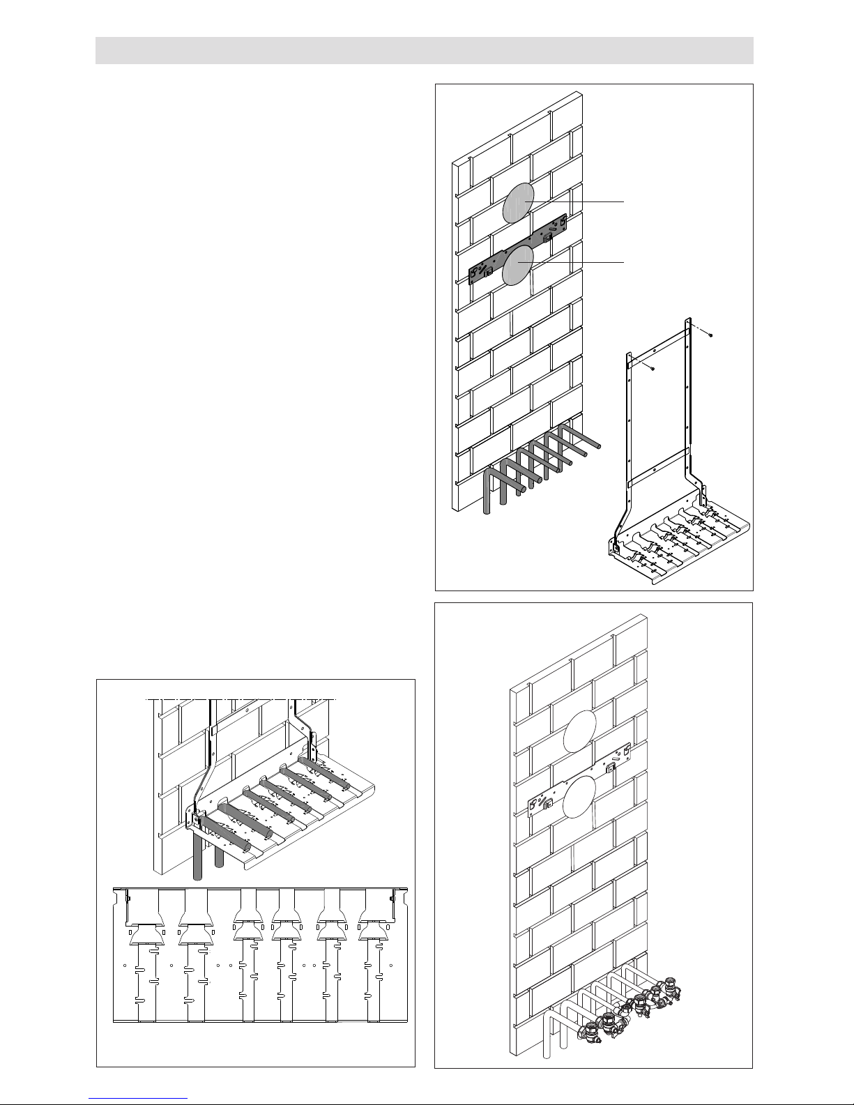
28
5.1 DELIVERY
Due to the weight of the appliance it may be necessary for two
people to lift and attach the appliance to its wall bracket. The
appliance is contained within a heavy-duty cardboard carton.
Lay the carton on the oor with the writing the correct way up.
5.2 CONTENTS
Contained within the carton is:
• the boiler
• the wall bracket
• carton template
• an accessories pack containing appliance service connections
and washers
• the instruction pack containing the installation, servicing & user
instructions, guarantee registration card and a 3-amp fuse.
5.3 UNPACKING
At the top of the carton pull both sides open – do not use a
knife – unfold the rest of the carton from around the appliance,
carefully remove all protective packaging from the appliance and
lay the accessories etc. to one side. Protective gloves should
be used to lift the appliance, the appliance back-frame should
be used for lifting points.
5.4 PREPARATION FOR MOUNTING THE
APPLIANCE
The appliance should be mounted on a smooth, vertical,
surface, which must be capable of supporting the full weight of
the appliance. Care should be exercised when determining the
position of the appliance with respect to hidden obstructions
such as pipes, cables, etc.
When the position of the appliance has been decided – using
the template supplied – carefully mark the position of the wall
mounting bracket and ue-hole (if applicable).
5.4.1 FITTING THE PRE-FIXING JIG (optional)
When the position of the appliance has been decided – using
the template supplied – carefully mark the position of the wall
mounting bracket/pre-xing jig and ue-hole (if applicable).
Once the pre-xing jig is in place, the pipework can now be
tted. Fit the pipework to sit within the pre-formed guides of
the xing jig and to the required length for either a standard
wall or standoff bracket.
Once the pipes have been tted, the jig can now be removed.
SECTION 5 - INSTALLATION
1
1
1
1
1 1
2
2
2 2
2 2
3
3
3
3
3
3
4 4
4
4
4
4
Top ue
Rear ue
use position 2
Fig. 9
Fig. 8
Fig. 10
Page 29
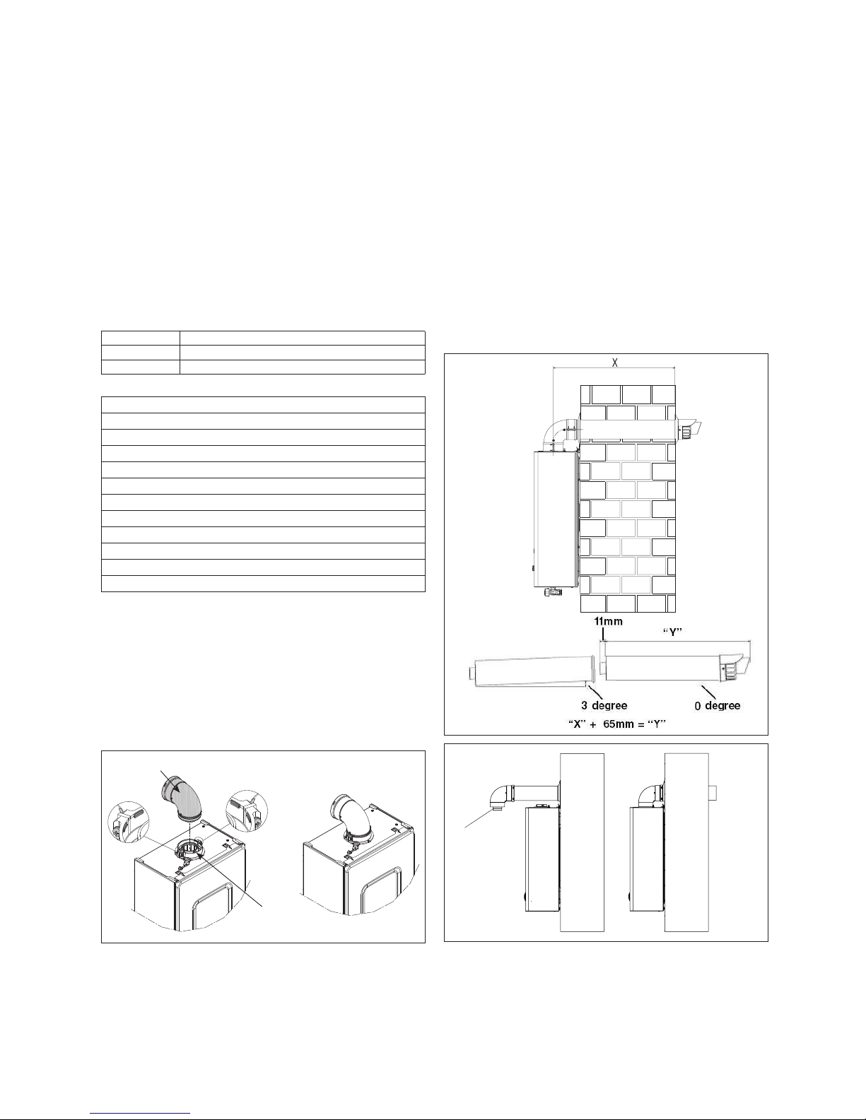
29
5.5 FITTING THE FLUE
This appliance incorporates a ‘click-t’ ue connection at the top
of the appliance, and also incorporates a rear-ue connection.
Should the rear-ue connection be preferred, the ue outlet will
require to be re-congured from a top outlet to a rear outlet.
Please refer to section 5.5.1.2 and the instructions supplied
with the rear-ue kit (code 29450133) on how to re-congure
the ue outlet and how to install the rear-ue terminal.
5.5.1 CONCENTRIC HORIZONTAL FLUE
These instructions relate specically to the installation of
this appliance with the Vokera 60/100mm ‘X-type’ (click-t)
ue terminals and accessories. For specic instructions on
installing this appliance with an alternative Vokera ue system,
e.g. 80/125mm; please refer to the instructions supplied with
the specic ue system, or download the instructions from the
Vokera website. The appliance ue outlet elbow can be rotated
through 360º on its vertical axis. In addition the ue may be
extended from the outlet elbow in the horizontal plane (see 2.9).
A reduction must also be made to the maximum length (see
table below) when additional bends are used.
Reduction for additional bends
Bend Reductioninmaximumuelengthforeachbend
45º bend 1.0 metre
90º bend 1.0 metre
Horizontal ue terminals and accessories
Code Description Length
20122759 XF standard horizontal ue kit TBC
20122761 XT telescopic ue kit TBC
29450123 90-degree bend N/A
29450124 45-degree bends (2) N/A
29450125 500mm extension 500mm
29450126 1000mm extension 1000mm
29450127 2000mm extension 2000mm
29450128 Telescopic extension 372/519mm
29450133 Rear-ue terminal kit TBC
522 Plume management kit 1370mm
529 100mm ue brackets (5) N/A
Using the template provided (A), mark and drill a 125mm hole
for the passage of the ue pipe. Each horizontal terminal,
incorporates an incline on the inner (60mm) pipe; this enables
the terminal to be installed on a level plane. However any
extended horizontal ue runs must incorporate a 3-degree fallback from the ue terminal towards the appliance. The xing
holes for the wall-mounting bracket should now be drilled and
plugged, an appropriate type and quantity of xing should be
used to ensure that the bracket is mounted securely. Once the
bracket has been secured to the wall, mount the appliance
onto the bracket.
Fig. 11
ange installed
as standard
A
A
C
B
90° bend
C
FITTING THE HORIZONTAL FLUE KIT
Carefully measure the distance from the centre of the appliance
ue outlet to the edge of the nished outside wall (dimension X).
Add 65mm to dimension X to give you Dimension Y (see g. 12).
Measure dimension Y from the terminal end of the concentric
ue pipe and cut off the excess ensuring any burrs are removed.
IMPORTANT: The X-type ue terminals are supplied with
a sachet of silicone lubricant; smear a small amount of the
lubricant around both inner and outer connections, at both
ends of the ue bend.
NOTE: Attach the decorative white plastic trim to the ue pipe
at this point if it’s required.
Attach the ue bend to the ue terminal ensuring that both pipes
are fully inserted into the ue bend. Insert the assembled ue
terminal and bend into the pre-drilled hole and offer up the ue
bend to the appliance ue spigot.
NOTE: The appliance incorporates a ‘click-t’ ue connection
(see g. 11). Ensure that both screws ‘C’ (g. 11) on the ‘clickt’ have been slackened off. Ensure that the bend is correctly
aligned with the connector and insert the ue bend into the
connector until it clicks into position (this is when the tabs at
points ‘A’ are located in the groove of the ue bend - see g.
11). Both screws (C) should now be tightened.
NOTE: If more convenient, the ue bend can be attached to the
appliance before connecting it to the ue terminal.
NOTE: Ensure that the outlet of the ue terminal is correctly
orientated as shown in g. 12.
NOTE
You must ensure that the entire ue system is properly supported
and connected. Seal the ue assembly to the wall using
cement or a suitable alternative that will provide satisfactory
weatherproong. The exterior trim can now be tted.
Fig. 12
Fig.13
A
EXTENDING THE FLUE
Connect the bend - supplied with the ue terminal - to the
appliance ‘click-t’ connector.
IMPORTANT: The X-type ue terminals are supplied with
a sachet of silicone lubricant; smear a small amount of the
lubricant around both inner and outer connections, at both
ends of the ue bend.
NOTE: The appliance incorporates a ‘click-t’ ue connection
(see g. 11). Ensure that both screws ‘C’ (g. 11) on the ‘clickt’ have been slackened off. Ensure that the bend is correctly
Page 30
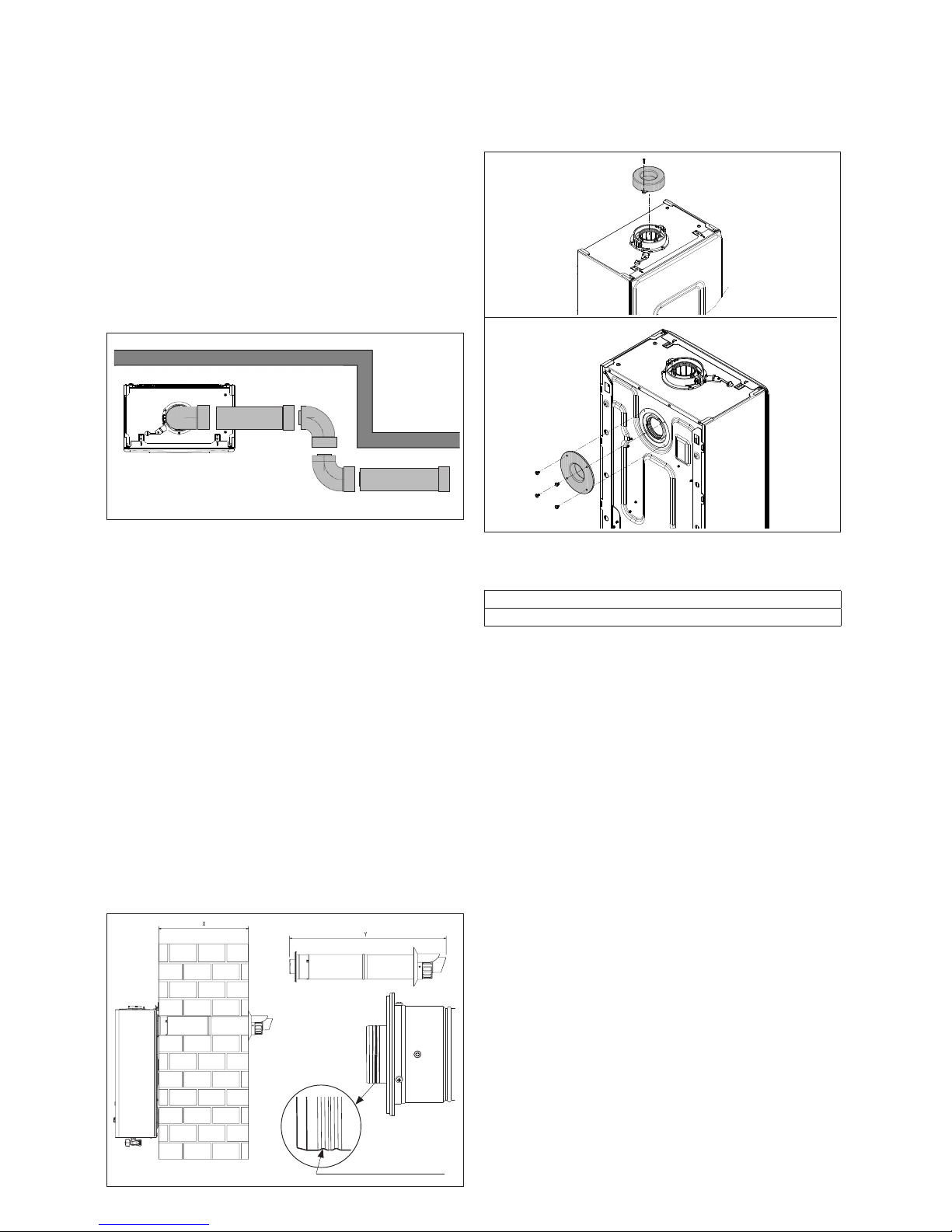
30
Fig. 14
aligned with the connector and insert the ue bend into the
connector until it clicks into position (this is when the tabs at
points ‘A’ are located in the groove of the ue bend - see g.
11). Both screws (C) should now be tightened. The additional
bends & extensions have push-t connections, care should be
taken to ensure that the correct seal is made when assembling
the ue system. Connect the required number of ue extensions
or bends (up to the maximum equivalent ue length) to the ue
terminal (see g. 11-14). The ue system should have a 3º rise
from the boiler to outside, to ensure any condense uid that
forms, is allowed to drain back to the appliance.
NOTE
When cutting an extension to the required length, you must
ensure that the excess is cut from the plain end of the extension
(see g. 11-14). Remove any burrs, and check that all seals are
located properly. You must ensure that the entire ue system is
properly supported and connected. Seal the ue assembly to
the wall using cement or a suitable alternative that will provide
satisfactory weatherproong. The interior and exterior trim can
now be tted.
5.5.1.2 FITTINGTHEREARFLUE(g.15)(rearueoutlet
only)
Refer to g. 16 & 17 and the instructions supplied with the rearue kit (code 29450133) for details on how to re-congure the
appliance from a top outlet to a rear outlet.
Using the template provided, mark and drill a 125mm hole
for the passage of the ue pipe. The hole should be drilled
LEVEL as the terminal already incorporates a fall-back to
the appliance. The xing holes for the wall-mounting bracket
should now be drilled and plugged, an appropriate type and
quantity of xing should be used to ensure that the bracket is
mounted securely. Once the bracket has been secured to the
wall, attach the rear ue terminal to the appliance (using the
previously retained screws) and x the telescopic terminal to
the correct length (wall thickness) ensuring that the terminal
will protrude through the wall by the correct distance.
Once the terminal has been adjusted to the correct length,
ensure that the ue outlet is orientated to the correct position,
and then insert the xing screw (supplied) and attach the
sealing strip (supplied) at the ue joint.
NOTE: If required the telescopic section that incorporates the
ue outlet can be trimmed to reduce its length.
NOTE:Theinner60mmpipeoftherearueterminalmust
becutby8mmatthepointindicated(g.15pos.A).
At this point, lift the appliance and carefully insert the terminal
into and through the wall, ensuring that the wall bracket
engages with the corresponding holes at the top of the
appliance.
A: cutting 8mm
pre-shearing
Fig.15
When reconguring the outlet from a top to a rear outlet, it is
necessary to remove the ‘click-t’ connector; replace all but
one of the securing screws - using the remaining screw to
secure the top outlet cap (g. 16).
When removing the rear outlet cap; retain the 4-screws as
these are required to attach the rear-ue terminal to the
appliance (g. 17).
Fig.17
Fig.16
Seal the ue assembly to the wall using cement or a suitable
alternative that will provide satisfactory weatherproong. The
exterior wall trim can now be tted.
Part No. Description Length
29450133 Rear ue terminal 825mm
5.5.2 CONCENTRIC VERTICAL FLUE
Using g.19 as a reference, cut a 110mm diameter hole in
the roof and/or ceiling to facilitate the route of the vertical ue
system. NOTE: ensure that the top of the appliance - if already
in position - is covered and protected from the possibility of any
dust or debris falling or entering the appliance via the ue outlet.
Fit the appropriate ashing to the roof and insert the vertical ue
terminal through the ashing from outside, ensuring that the
collar of the terminal is located over the outlet of the ashing.
The xing holes for the appliance wall mounting bracket should
now be drilled and plugged. An appropriate type and quantity
of xing should be used to ensure that the bracket is mounted
securely. Once the bracket has been secured to the wall, mount
the appliance onto the bracket.
If the vertical ue system requires additional extensions or bends,
connect these to the vertical terminal, ensuring the following:
- the maximum permitted ue length is not exceeded
- reductions to the maximum ue length have been made for
any bends that are used on the vertical ue system
- any horizontal sections of the ue system, incorporate a
3-degree fallback to the appliance
- the entire ue system is fully supported and secured using
the appropriate brackets
- if/when an extension is cut to a shorter length, ensure that
the excess length is cut from the plain end of the extension,
and that any burrs or rough edges are removed
- all seals are properly located before assembling or connecting
the ue system.
IMPORTANT: The VX ue terminal is supplied with a sachet of
silicone lubricant; smear a small amount of the lubricant around
both inner and outer connections, at both ends of the vertical
ue connector (supplied with the VX terminal).
NOTE: The appliance incorporates a ‘click-t’ ue connection
(see g. 18). Ensure that both screws ‘C’ (g. 11) on the ‘click-t’
have been slackened off. Ensure that the connector is correctly
aligned with the ‘click-t’ and insert it into the ‘click-t’ until it
Page 31
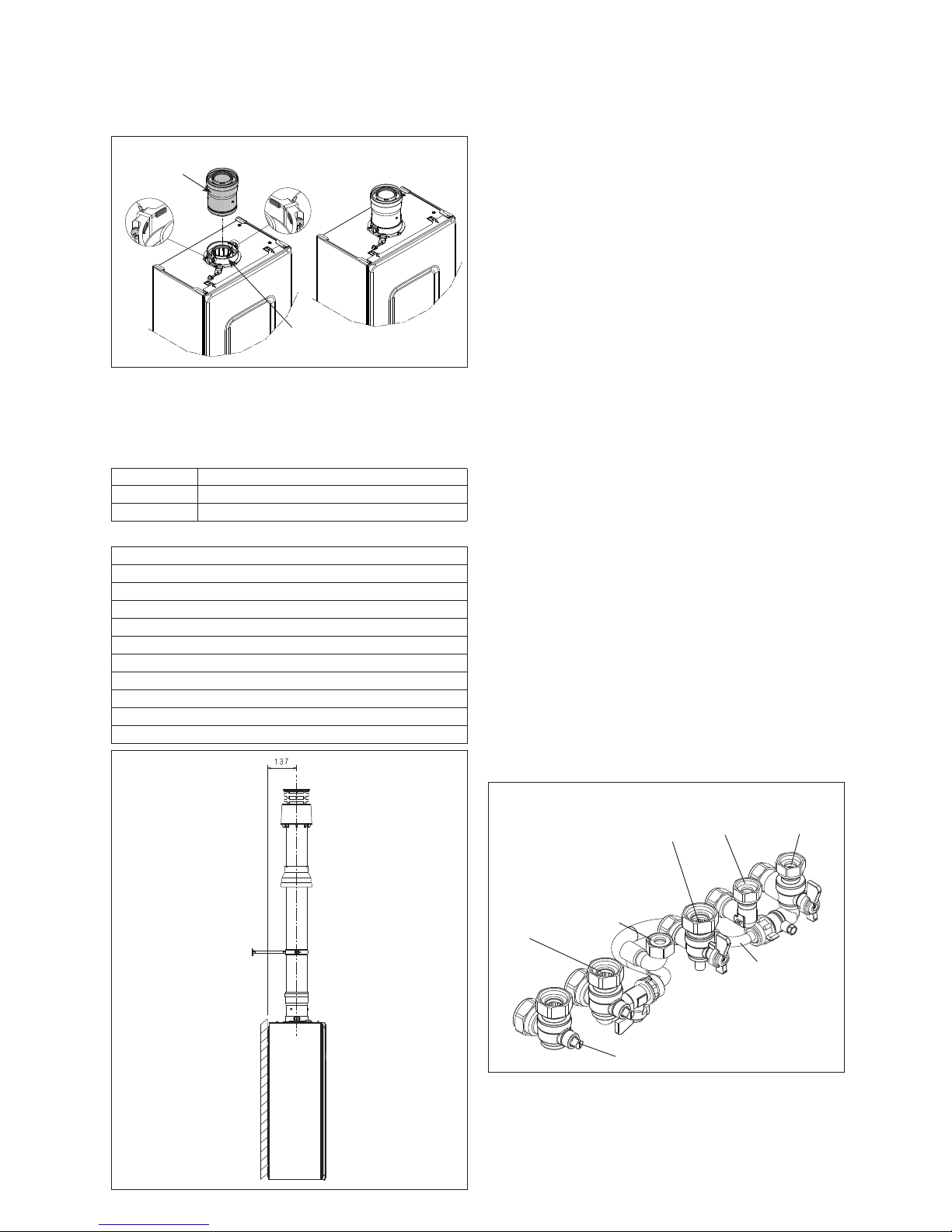
31
clicks into position (this is when the tabs at points ‘A’ are located
in the groove of the vertical ue connector - see g. 18). Both
screws (C) should now be tightened.
NOTE: If more convenient, the vertical ue connector can be
attached to the vertical ue terminal/extension before connecting
it to the appliance.
vertical
connection
A
A
C
C
B
ange installed
as standard
Fig.18
NOTE
Additional bends and/or extensions can be connected to the
terminal connector if desired, however if additional bends are
tted, a reduction must be made to the maximum ue length
(see table below).
Reduction for bends
Bend Reductioninmaximumuelengthforeachbend
45º bend 1.0 metre
90º bend 1.0 metre
Vertical ue terminal and accessories
Code Description Length
20122763 Vokera XV Vertical Flue kit 1000mm
29450123 90-degree bend N/A
29450124 45-degree bends (2) N/A
29450125 500mm extension 500mm
29450126 1000mm extension 1000mm
29450127 2000mm extension 2000mm
29450128 Telescopic extension 372/519mm
529 100mm ue brackets (5) N/A
531 Pitched roof ashing N/A
532 Flat roof ashing N/A
Fig. 19
IMPORTANT
The vertical ue terminal is 1.0 metre in length and cannot be
cut; therefore it may be necessary to adjust the height of the
appliance to suit or use a suitable extension.
5.6 CONNECTING THE GAS AND WATER
The appliance is supplied with an accessory pack that includes
service valves. The service valves are of the compression type.
The accessory pack contains sealing washers’ etc, for use with
the service valves. When connecting pipe work to the valves,
tighten the compression end rst then insert the sealing washers
before tightening the valve to the appliance.
NOTE
It will be necessary to hold the valve with one spanner whilst
tightening with another.
5.6.1GAS(g.20)
The appliance is supplied with a 15mm service valve, connect
a 15mm pipe to the inlet of the valve and tighten both nuts.
NOTE
It will be necessary to calculate the diameter of the gas supply
pipe to ensure the appliance has an adequate supply of gas.
5.6.2FLOW&RETURN(g.20)
The appliance is supplied with 22mm service valves for the
ow and return connections, connect a 22mm pipe to the inlet
of each valve and tighten both nuts.
NOTE
Depending on system requirements, it may necessary to increase
the size of the ow & return pipe work after the service valve
connections.
5.6.3COLDWATERINLET(g.20)
The appliance is supplied with a 15mm combined stopcock and
lling valve, connect a 15mm pipe to the inlet of the stopcock
and tighten both nuts.
5.6.4HOTWATEROUTLET(g.20)
The appliance is supplied with a 15mm outlet connection, connect
a 15mm pipe to the outlet connection and tighten both nuts.
5.6.5SAFETYVALVE(g.20)
Connect the safety valve connection pipe to the safety valve
outlet and tighten. The discharge pipe must have a continuous fall
away from the appliance to outside and allow any water to drain
away thereby eliminating the possibility of freezing.
The discharge pipe must terminate in a position where any water
- possibly boiling - discharges safely without causing damage or
injury, but is still visible.
Fig. 20
Hot water
outlet
Cold water
inlet
stopcock
C/H return valve
C/H ow
valve
Safety valve
outlet
Gas
cock
Filling loop
5.6.6 CONDENSATE DISPOSAL
This appliance will - under normal operating conditions - produce
condensate uid that will require to be disposed of via the
dwelling’s waste water drainage system.
Vokera strongly recommends that the condensate pipe is
connected to the internal waste water pipework in accordance
with BS6798.
Page 32
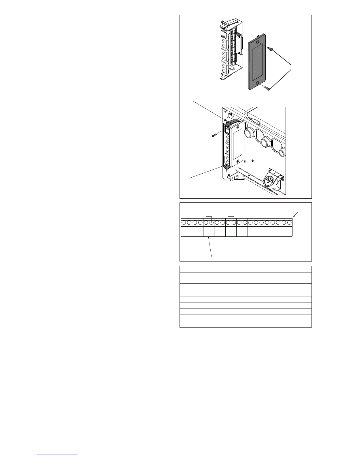
32
BS6798 provides comprehensive instruction and advice on all
permissible condensate disposal methods; notwithstanding this,
it is essential that the following is strictly adhered to:
- use only plastic drainage pipe (minimum OD of 21.5mm)
- horizontal runs must incorporate a minimum 45mm fall per
metre, away from the appliance
- external pipework and/or pipework in unheated areas, must
have a minimum OD of 32mm and be insulated with Class-O
pipe insulation
- the route, type, and termination of the condensate disposal
method, must not permit any spillage of condensate uid,
into the dwelling in the event of a blockage or freezing of the
condesate pipework.
Should it not be possible to route and terminate the condensate
pipework internally using ‘gravity discharge’; Vokera
recommends that the Vokera condensate pump (code 404) be
considered as an alternative solution.
Ensure that the end-user is aware of the effect/consequences
of the condensate pipework becoming blocked or frozen.
5.7 ELECTRICAL CONNECTIONS
The boiler is supplied with a y-lead. This lead can be used for
connection to the electrical supply. Connect the y-lead to a
fused plug or fused isolator in the following way:
• brown wire to LIVE supply
• blue wire to NEUTRAL supply
• green/yellow to EARTH connection.
Insert the supplied 3-AMP fuse into the fused isolator or fused
plug.
Should the y-lead be unsuitable, refer to 5.7.3 for details on
how to connect the electrical supply directly to the boiler.
The electrical supply must be as specied in section 4/4A.
A qualied electrician should connect the appliance to the
electrical supply. If controls - external to the appliance - are
required, a competent person must undertake the design of
any external electrical circuits, please refer to section 8 for
detailed instructions. ANY EXTERNAL CONTROL OR WIRING
MUST BE SERVED FROM THE SAME ISOLATOR AS THAT
OF THE APPLIANCE. The supply cable from the isolator to the
appliance must be 3-core exible sized 0.75mm to BS 6500 or
equivalent. Wiring to the appliance must be rated for operation
in contact with surfaces up to 90 ºC.
The appliance is supplied with a ‘D-sub’ interface, that enables
various control congurations to be connected to the appliance
without any need for the removal of the casing.
NOTE: The appliance will enter a fault condition if/when the D-sub
interface is removed or incorrectly attached to the appliance.
For detailed wiring information and schematic diagrams see
Section 8.
D-sub Interface
- Loosen cover retaining screws (V) and remove cover.
- Refer to g. 22 and below for relevant wiring connections for
the envisaged controls regime:
- TA (5 & 6) - for use with a ‘voltage-free’ control, e.g. room
thermostat and/or clock (remove link wire)
- OT+ (13 & 14) - for use with BeSMART control
- SE (11 & 12) - for use with an external temperature sensor
- TBT (9 & 10) - for use as a fail-safe if/when an external
device fails, e.g. condensate pump.
- Make the required connections.
- Replace cover and re-tighten securing screws.
- Press and hold both tabs and insert the D-sub interface into
the D-sub socket on the appliance underside (g. 21).
- Tighten the securing screw V1.
Fig. 21
V
V1
Fig. 22
1
2
3
4
5
6
7
8
9
10
11
12
13
14
15
16
17
18
19
20
-
A
B
+
TA
TBOL
TBT
SE
OT+
SBOL
X1
X2
M20
D
Voltage free contact input
1-2-3-4
(- A B +)
Bus 485
5-6 TA Room thermostat
(contact must be free of voltage)
7 - 8 TBOL Not used
9-10 TBT Low temperature limit thermostat
11-12 SE Outdoor temperature sensor
13-14 OT+ Open therm
15-16 SBOL Not used
17-18 X1 Not used
19-20 X2 Not used
Opentherm Control
When an OT control is connected to the appliance, the UI
screen will display ‘Opentherm Connected’. The control
functions of the appliance UI will be transferred to the OT
control, which can then be used to set/adjust the main heating
zone settings and the hot water settings.
UI Functions When OT Control is Connected
STATE function is disabled on the UI and must be set/adjusted
via the OT control. The outlet HW temperature cannot be
adjusted via the appliance UI, and is set/adjusted via the OT
control.
INFO Menu
When an OT control is connected, the info menu will display
the HW set-point instead of the HW ow-rate.
NOTE
All/any functions of the ‘main’ zone are disabled on the
appliance UI and can only be accessed/adjusted via the OT
control.
Page 33
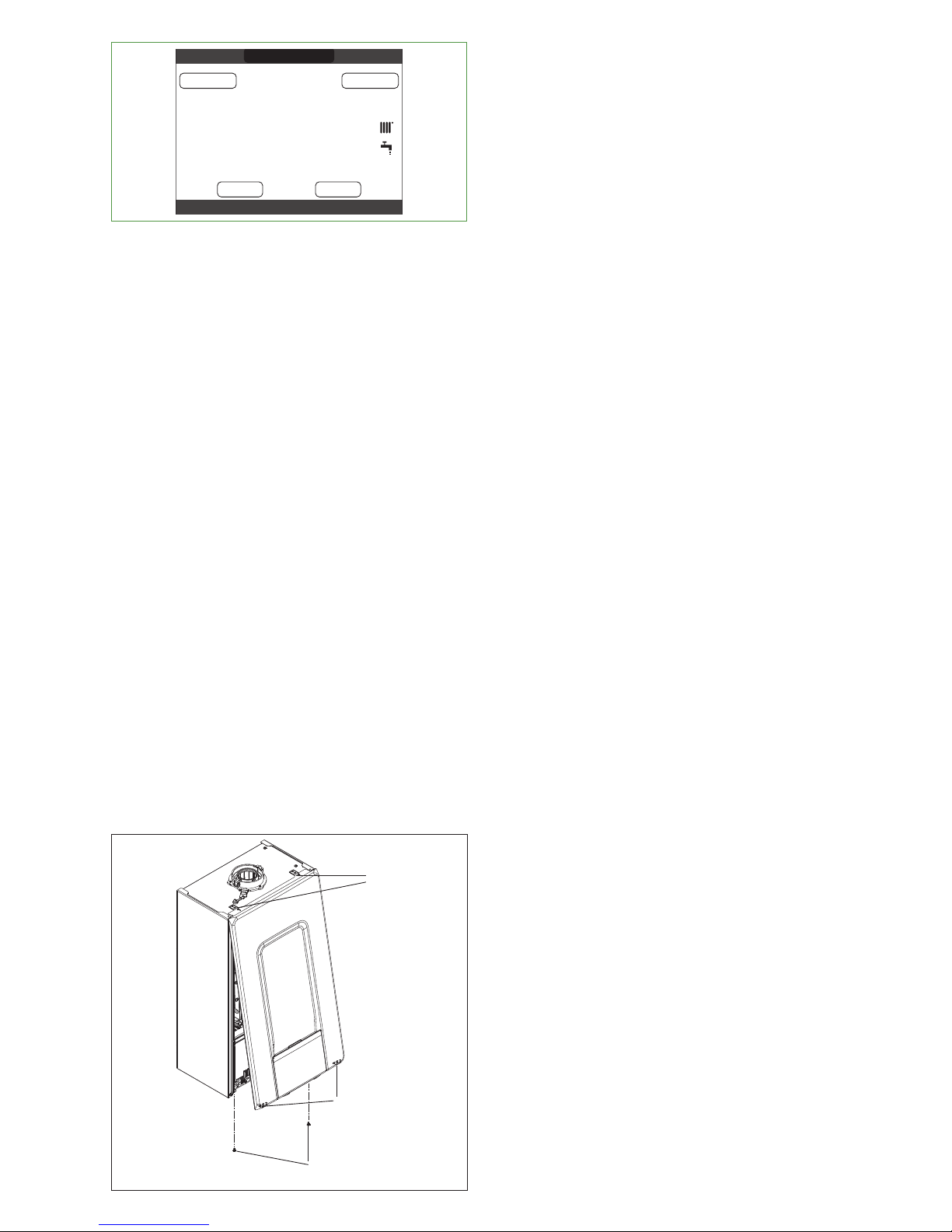
33
18/05/2013 12:17
MENU
INFO SET
42
°C
1.5
bar
FRI
PLANT
HOT WATER TEMPERATURE
STATE
Open Therm connected
5.7.1 FRONT COVER REMOVAL
Refer to g. 23.
- Locate and remove screws ‘A’ that secure the spring clips to
the underside of the appliance.
- Gently unclip the spring clips ‘C’ and pull the front cover
outwards and then upwards in order to disengage it from the
tabs ‘B’ at the top of the appliance.
- Place the front cover in a safe area to avoid any risk of damage.
- Replace in the reverse order.
REMOVAL OF SIDE PANEL/S
Remove the front cover as indicated above:
- locate and remove the 2-screws that secure the side panel
to the appliance
- gently prise the side panel forward to release it from the
securing tabs on the appliance rear
- replace in the reverse order.
WARNING
b
DO NOT remove the ‘side’ panels if/when the appliance
has been installed to within the minimum clearances,
i.e. 2mm.
When retting the side panels, it is essential that the LH
panel is tted to the left side and the RH panel is tted to
the right side (refer to the attached label).
b
The front cover and
side panels are an intrinsic part
of the ‘room-sealed’ element of the appliance; any
damage that results in a loss of their integrity will
require the replacement of the cover.
b
The noise absorbing panels that are located inside
the front cover and side panels also act as seals to
ensure airtightness and the room-sealed integrity of
the appliance. It is essential that these are correctly
positioned during the retting of the front cover
and/or side panels. Any subsequent damage or
deterioration to the noise absorbing panels must be
rectiedbeforetheappliancei
s put back into service.
B
A
C
Fig. 23
5.7.2 APPLIANCE MAIN ELECTRICAL SUPPLY INPUT
The appliance is supplied with an electrical y-lead (approx.
1.5m long) and the D-sub interface has a link wire inserted
across the TA terminals (5 & 6); these measures enable the
basic function of the appliance once the y-lead is connected
to the electrical supply. However if this is not suitable, then it is
possible to remove and replace the ‘y-lead’ with an alternative
method of connection to the electrical supply.
5.7.3 CONNECTING A 230V SUPPLY TO THE
APPLIANCE PCB
WARNING
Isolate the appliance from the electrical supply before
carrying out this procedure.
Remove the front cover as detailed in 5.7.1. Locate the red
clip that retains the control panel in the upright position and
move it to the left to release the control panel.
Lower the control panel and remove the two PCB cover
retaining screws (located adjacent to the PCB’s front retaining
clips).
Push in the two front clips, and pull out the side clip in order
to release the cover and then remove the cover - lifting from
the front upwards.
The 230v electrical supply input is located at the rear right
hand side of the PCB (see Section-8 schematics); disconnect
and remove the factory-tted y-lead, and use the same
cable-entry point, route, and respective electrical terminals for
the new 230v supply cable.
NOTE
Ensure that the Earth wire is approximately 30mm longer that
the Live and Neutral wires; and that each terminal screw is
tight.
Carry out any relevant electrical checks as detailed in 8.5
before replacing the PCB cover; ensuring that no cables or
wiring is trapped.
Ret the PCB cover screws and move the control panel back
to the upright position ensuring the red securing clip, clicks
into place.
Replace the appliance front cover as detailed in 5.7.1 paying
attention to the importance of ensuring the cover is providing
an effective seal.
NOTE
It is the installer and/or electrician’s responsibility to ensure
that the appliance properly earthed. Vokera Ltd. cannot
be held responsible for any damages and/or injuries that
result from the incorrect wiring of the appliance; or from an
ineffective/defective Earth connection.
Page 34
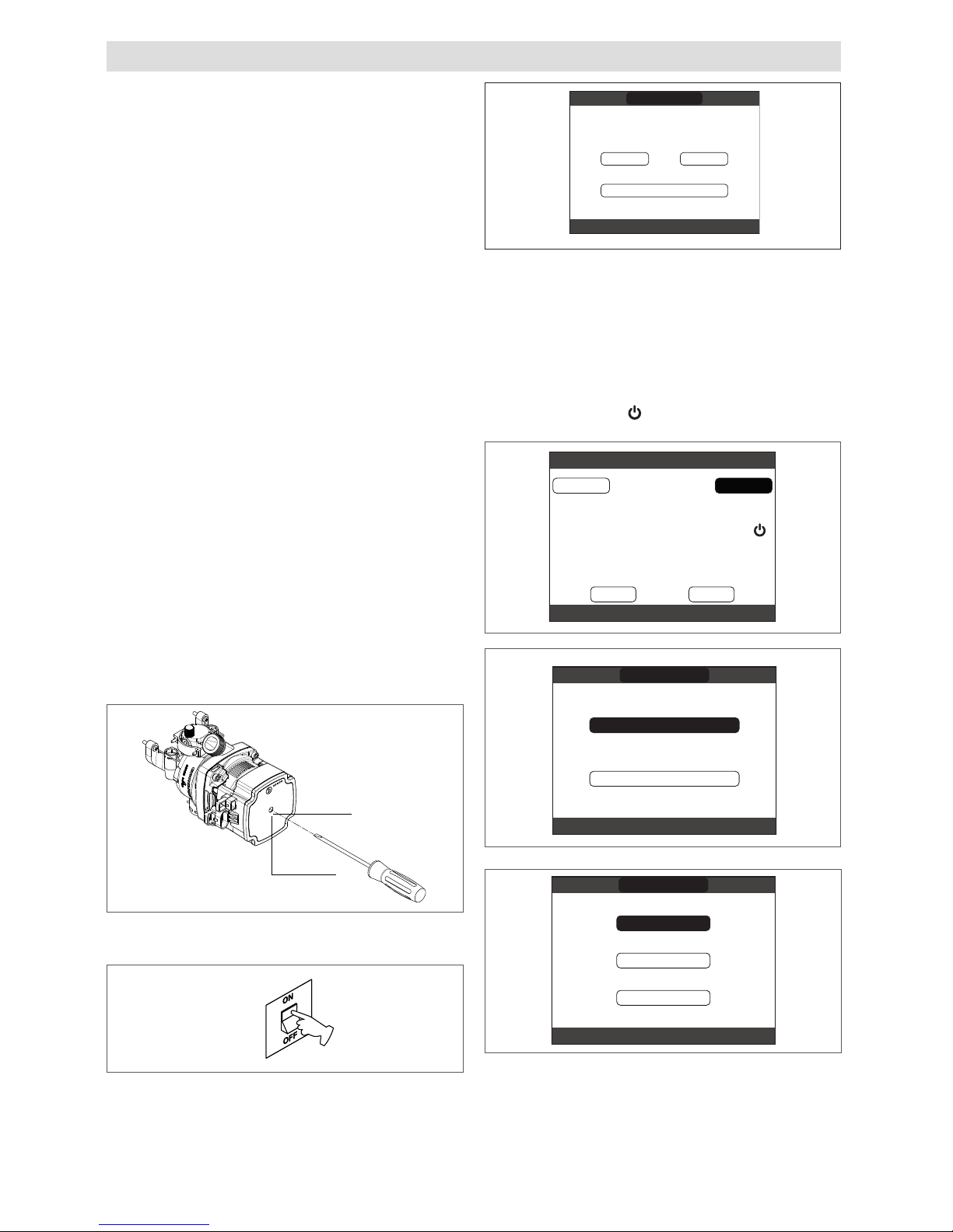
34
SECTION 6 - COMMISSIONING
6.1 PRELIMINARY CHECKS
Before starting up the boiler, check:
- conrm via the appliance data badge, that the appliance is
suitable/congured for the gas type and electrical supply
that has been provided to the appliance
- inspect the entire ue system and ensure that it has been
installed in accordance with these instructions and the
relevant standards that apply locally and/or nationally
- that the required clearances have been met in respect of the
requirements for maintenance
- inspect the entire installation including the gas meter, test
for tightness and purge. Refer to BS 6891 (I.S. 813 in ROI)
for specic instruction
- ensure that the rated delivery of the gas meter is adequate
enough to serve this appliance and any other gas appliance
connected to the same meter
- ensure that the gas supply pipework is of adequate size to
provide the maximum gas rate required by this appliance.
6.1.1 FIRST IGNITION ERRORS
- Ensure that the gas supply is ON, water supply is ON, and
electrical supply is ON. Ensure that the system pressure is
at least 0.6 bar.
- D-sub interface incorrectly located (alarm code E077);
ensure that the D-sub interface is located within the guide
slot (g. 21).
- Pump rotator shaft seized (possible alarm code E020 and
no circulation within boiler/heating system); this can occur
if the appliance has been stored or inactive for a prolonged
period.
- To ‘release’ the seized rotator shaft:
- remove front cover as detailed in 5.7.1
- refer to g. 24 and locate the hole (1) that allows access
to the shaft centre screw (a)
- insert an N2 Phillips screwdriver (b) into the screw-head,
gently push forward and turn the shaft with the screwdriver
- this will release the rotator shaft
- replace the front cover as detailed in 5.7.1 ensuring
correct seal.
a
b
1
Fig. 24
6.2 PROGRAMMING THE BOILER
- Position the system’s main switch to the “on” position.
- If necessary set the TIME and DATE setting the HOURS,
MINUTES, DAY, MONTH and YEAR with the keys “up”
and “down”, confirming the selection.
-
12 17:
ENTER TIME AND DATE
TIME & DATE
USE THE ARROWS TO MODIFY
18 / 11 / 2013
Note: it is possible to change the TIME and DATE settings,
as well as LANGUAGE and the duration of the back-lighting,
at any time by entering the MENU from the main screen and
then selecting SETTINGS.
b
Whenever the power supply to the appliance is
interrupted and then restored, an automatic venting
cycle is carried out lasting 2 min. To interrupt the vent
cycle, carry out the procedure explained in the section
“6.3 First commissioning”
.
- Set the boiler to OFF from REC10 selecting the status
menu and then BOILER.
18/05/2013 12:17
MENU
INFO SET
42
°C
1.3
bar
FRI
PLANT
HOT WATER TEMPERATURE
STATE
STATE
BOILER
MAIN ZONE
-
BOILER
OFF
SUMMER
WINTER
Through the REC10 it is possible to access, using the
TECHNICAL menu, a series of parameters that can be
programmed to allow you to personalise the operation of the
boiler based on the type of system.
- Then set the parameters according to the desired operating
modes.
Page 35
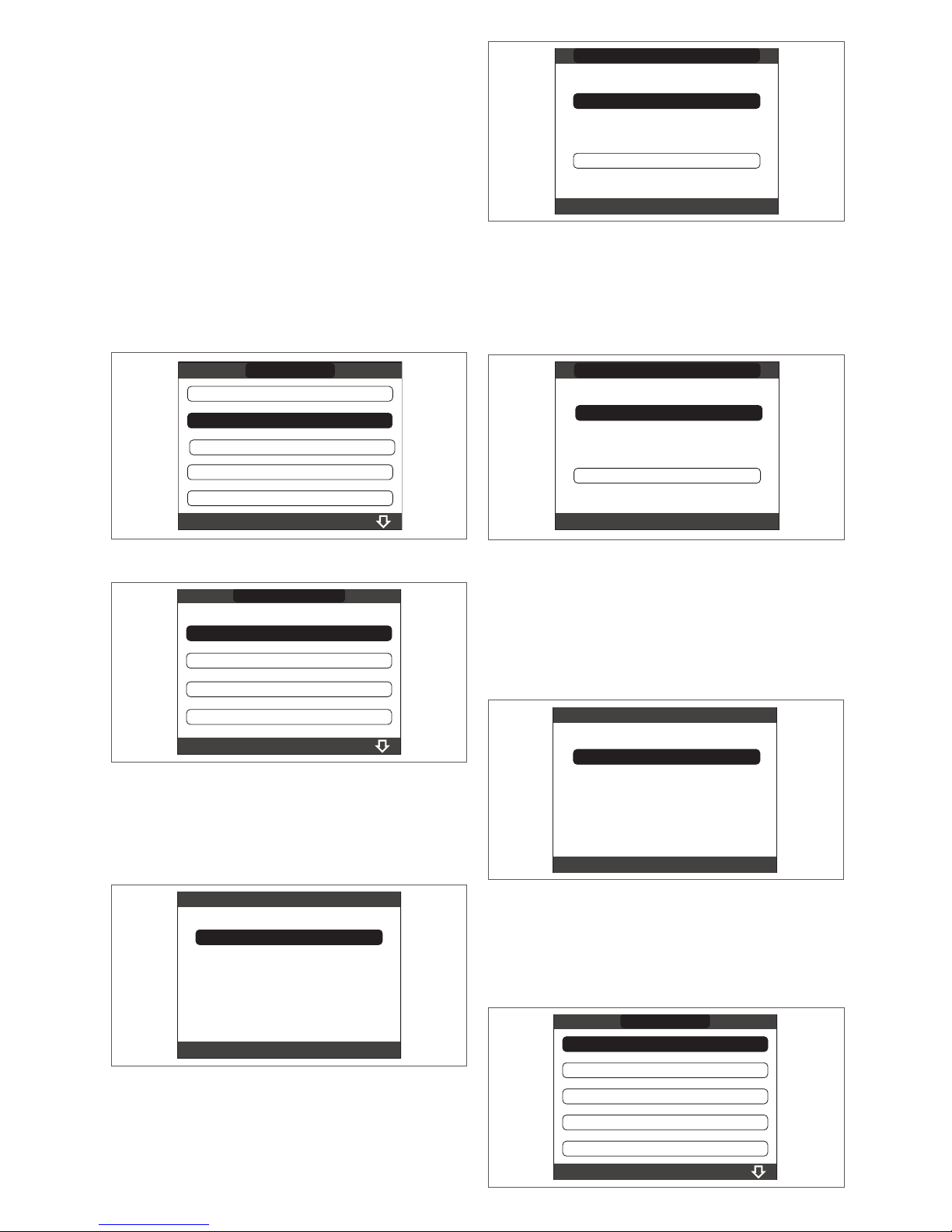
35
6.2.1 BOILER CONFIGURATION
The REC10 UI is supplied with a default conguration that
enables a standard type of external control, e.g. room
thermostat & clock, programmable room thermostat, etc. to
be connected to the appliance or alternatively the Vokera
BeSMART OT+ control. Alternatively and if desired the
embedded 7-day clock can be enabled (default is disabled) to
control the ON/OFF time schedule for the central heating. In
order to enable the embedded clock, it is necessary to access
the ‘INSTALLATION’ parameters as dened in section 8 (see
also menu hierarchy on page 18).
NOTE
Do not enable the embedded clock if another type of timing
control, e.g. time clock, programmable room thermostat, etc.
is – or will be – connected to the appliance, in order to manage
the heating timing schedule.
The following functions can also be accessed and adjusted via
the installer parameters (see section 8 & page 18) if required/
necessary.
NOTE
The ‘installer’ parameters should only be accessed and
adjusted by suitably qualied personnel.
TERMOREGOLAZIONE
PARAMETERS
INSTALLATION
THERMOREGULATION
RANGE RATED
TECHNICAL
INSTALLER
CALIBRATION
- Select from among the following options with the “up” and
“down”, keys, confirming the selection.
-
PARAMETERS
INSTALLER
TIMER OFF CH
RESET TIMERS CH
PREHEATING
DHW THERMOSTAT
TIMER OFF CH
This parameter allows you to change the TIMER OFF
CH, regarding the delay time introduced for re-igniting the
burner in the face of an off due to the heating temperature
being reached. The factory setting for this parameter is 3
minutes and can be set to a value between 0 min and 20
min selecting the desired one with the “up” and “down”,
keys confirming the selection.
-
TIMER OFF CH
3
MIN
RESET TIMERS CH
This parameter allows you to reset the REDUCED HEATING
MAXIMUM OUTPUT TIMING, during which the speed of
the fan is limited to 75% of the maximum heating output
that has been set, and the TIMER OFF CH. The factory
setting for this parameter is FUNCTION INACTIVE, select
FUNCTION ACTIVE using the keys “up” and “down”,
confirming the selection for resetting the timings.
FUNCTION NOT ACTIVE
RESET TIMER CH
FUNCTION ACTIVE
INSTALLER
- DOMESTIC HOT WATER THERMOSTAT
This parameter allows you to set the type of DOMESTIC
HOT WATER THERMOSTAT.
The factory setting for this parameter is RELATED, i.e. for
domestic hot water the boiler switches off at setpoint +5°C
and restarts at setpoint +4°C.
To select the ABSOLUTE values, where the boiler for
domestic hot water will still switch off at 65°C and restart at
63°C, use the keys “up” and “down”.
DHW THERMOSTAT
ABSOLUTE
INSTALLER
RELATED
- PREHEATING
Setting PREHEATING = 1 the boiler’s domestic hot water
function activates. This function keeps the water in the
domestic hot water exchanger hot, to reduce standby times
when a request is made. When the preheating function is
enabled the symbol P comes on with a steady light at the
top with respect to the hot water icon. During burner ignition
following a preheating request, the symbol P starts flashing.
To deactivate the preheating function, set the parameter to
PREHEATING = 0, the symbol P switches off.
The function is not active when the boiler is OFF.
TERMOSTATI SAN
PREHEATING
0
6.2.2 CONFIGURATION OF THE ZONE
It is possible to customise the management of the heating
zone by accessing the ZONES MANAGER menu.
- Access the technical parameters as explained in the section
“3.1 Access to the technical parameters”
.
- In sequence select INSTALLATION, ZONES MANAGER
and MODIFY ZONE with the “up” and “down” keys,
confirming the selection.
PARAMETERS
INSTALLATION
THERMOREGULATION
RANGE RATED
TECHNICAL
INSTALLER
CALIBRATION
Page 36
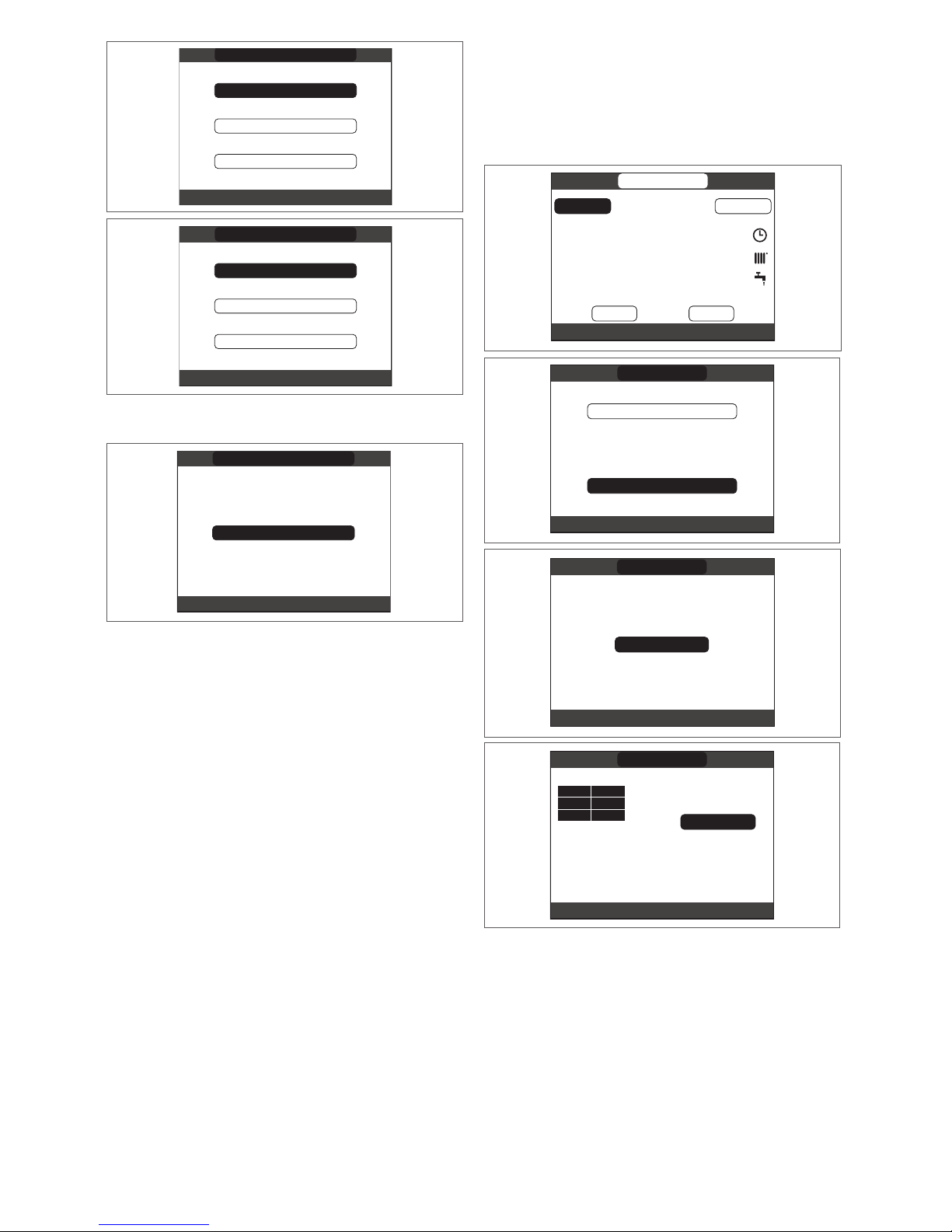
36
INSTALL
SENSOR CALIBRATION
INSTALLER
ZONES MANAGER
SYSTEM RESET
ADD ZONE
MODIFY ZONE
DELETE ZONE
INSTALL
INSTALLER
- Select the desired heating zone and then choose from
among the options with the “up” and “down” keys,
confirming the selection:
MAIN
INSTALLER
INSTALL
- TYPE OF ACTUATION
Set the parameter in question to ITRF05/AKM (default
value)
- TYPE OF HEAT REQUEST
This parameter allows you to specify the type of heat
request, it is possible to choose from among the following
options:
THERMOSTAT (factory setting): the heat request is
generated with an ON/OFF thermostat
REC10 MASTER: the heat request is generated by the
REC10 MASTER; in this case the REC10 assumes the
function of an HIU (Human Machine Interface)
- TYPE OF ZONE
This parameter allows you to specify the type of zone
to be heated, it is possible to choose from among the
following options:
HIGH TEMPERATURE (factory setting):
LOW TEMPERATURE
- MIN SET HEAT
This parameter allows you to specify the minimum heating
setpoint that is possible (range 20°C - 80.5°C, default
40°C for high temperature systems - range 20°C - 45°C,
default 20°C for low temperature systems)
- MAX SET HEAT
This parameter allows you to specify the maximum
heating setpoint that is possible (range 20°C - 80.5°C,
default 80.5°C for high temperature systems - range 20°C
- 45°C, default 45°C for low temperature systems)
- CHANGING NAME
This parameter allows you to attribute a specific name to
the heating zone
- POR (embedded clock function)
This parameter enables or disables the embedded clock.
Embedded clock disabled (default) = 0
Central heating is controlled (ON & OFF) by the room
thermostat connection (TA).
Embedded clock enabled = 1
Central heating ON/OFF times are controlled according to
the (default) heating programme, whilst room temperature
is controlled via the room thermostat (TA). Ensure that the
operating mode (‘STATE’ menu) is set to AUTO.
6.2.3 EMBEDDED CLOCK HEATING SCHEDULE
When the embedded clock is enabled (POR=1 - see above),
a default heating schedule is used to manage the ON/OFF
timings for each day of the week (operating mode = AUTO).
if necessary, the default heating schedule can be changed
according to the User’s needs. Refer to section 2.10 for
detailed instruction/guidance on how to access and change
the default heating schedule.
18/05/2013 12:17
30
°C
.3
1.3
bar
MENU
INFO SET
FRI
HOT WATER TEMPERATURE
STATE
PLANT
MON
SETTINGS
MENU
SELECT OPTION
TIME SCHEDULE
MON
18/11/2013 12:17
MAIN
SELECT THE ZONE
SCHEDULE
07:30
11:30
18:00
08:30
13:30
22:30
SELECT
A DAY
START
MAIN
THURSDAY
END
ZONE SCHEDULE
6.2.4 SETTING THE THERMOREGULATION
Thermoregulation (weather compensation) controlled by the
appliance, can only be enabled if an external sensor has been
installed and connected to the D-sub interface (SE terminals
11 & 12).
When the presence of an external sensor is detected, the
appliance immediately enables the thermoregulation function
and calculates a required outlet (flow) temperature that is
based on the external temperature and the chosen climatic
curve.
The temperature measured by the outdoor temperature
sensor is displayed on the initial page in the top right,
alternating with the display of the time.
When thermoregulation is enabled (outdoor temperature
sensor present), the algorithm for automatically calculating
the outlet setpoint depends on the type of heat request.
Page 37
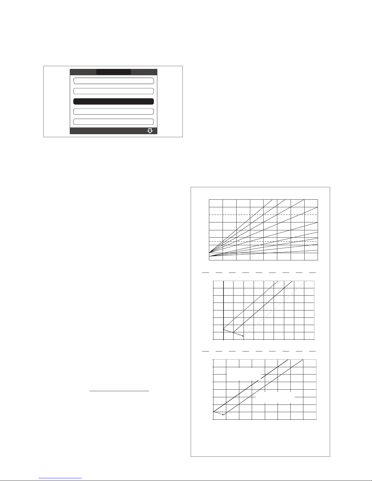
37
In any case, the thermoregulation algorithm will not directly
use the outdoor temperature, but rather a calculated outdoor
temperature that takes into account the building’s insulation:
in buildings that are well insulated, the outdoor temperature
variations will have less impact than those that are poorly
insulated by comparison. Enabling THERMOREGULATION
occurs in the following way:
- select THERMOREGULATION with the “up” and “down”
keys, confirming the selection.
PARAMETERS
THERMOREGULATION
RANGE RATED
TECHNICAL
INSTALLER
CALIBRATION
INSTALLATION
Using the REC10 it is possible to set the value of the following
parameters:
BUILDING TYPE
It is indicative of the frequency with which the value of
the calculated outdoor temperature for thermoregulation is
updated, a low value for this setting will be used for buildings
that have little insulation.
Setting range: [5min - 20min]
Factory setting: [5min]
REACTIVITY EXT SENSOR
It is an indication of the speed with which variations of the
measured outdoor temperature affect the calculated outdoor
temperature value for thermoregulation, low values indicate
high speeds.
Setting range: [0 - 255]
Factory setting: [20]
At this point, to change the value of the previous parameters,
proceed as described below:
- in sequence select THERMOREGULATION and TYPE OF
BUILDING rather than REACTIVITY EXT SENSOR with the
“up” and “down” keys, confirming the selection
- set the desired value with the “up” and “down” keys,
confirming the selection.
Note: The value of the calculated outdoor temperature used
by the thermoregulation algorithm is displayed in the INFO
menu under T EXT FOR THERMOREG.
HEAT REQUEST FROM THERMOSTAT or POR
(Programmable Timer)
In this case the outlet setpoint depends on the outdoor
temperature for obtaining a reference ambient temperature of
20°C. There are 2 parameters that compete to calculate the
output setpoint:
- slope of the compensation curve (KT)
- offset on the reference ambient temperature.
SELECTING THE COMPENSATION CURVE
The compensation curve for heating maintains a theoretical
temperature of 20°C indoors, when the outdoor temperature
is between +20°C and -20°C. The choice of the curve
depends on the minimum outdoor temperature envisaged
(and therefore on the geographical location), and on the
delivery temperature envisaged (and therefore on the type of
system). It is carefully calculated by the installer on the basis
of the following formula:
KT = T. outlet envisaged - Tshift
20- min. design external T
Tshift = 30°C standard system
25°C floor installations
If the calculation produces an intermediate value between two
curves, you are advised to choose the compensation curve
nearest the value obtained.
Example: if the value obtained from the calculation is 1.3, this
is between curve 1 and curve 1.5. Choose the nearest curve,
i.e. 1.5.
The settable KT values are as follows:
radiator system: 1.0-3.0
under floor heating system 0.2-0.8.
Using the REC10 it is possible to set the selected
thermoregulation curve:
- in sequence select THERMOREGULATION and CLIMATIC
CURVES with the “up” and “down” keys, confirming the
selection
- select the desired heating zone with the “up” and “down”
keys, confirming the selection
- set the desired climatic curve with the “up” and “down”
keys, confirming the selection.
OFFSET ON THE REFERENCE AMBIENT TEMPERATURE
In any event, the user can indirectly modify the value of
the HEATING setpoint inserting an offset on the reference
temperature that can vary within the range -5-+5 (offset 0 =
20°C).
NIGHT COMPENSATION
Whenever a programmable timer is connected to the
ROOM THERMOSTAT input, from the TECHNICAL\
THERMOREGULATION\CLIMATIC CURVES\MAIN the
NIGHT COMPENSATION function can be enabled.
In this case, when the CONTACT is CLOSED, the heat
request is made by the flow sensor, on the basis of the outdoor
temperature, to obtain a nominal ambient temperature on
DAY level (20°C).
The opening of the contact does not produce a switch-off,
but a reduction (parallel translation) of the climatic curve on
NIGHT level (16°C).
Also in this case, the user can indirectly modify the value of
the HEATING setpoint inserting once again an offset on the
reference DAY temperature (20°C) rather than NIGHT (16°C)
that can vary within the range [-5 - +5].
T80 std systems heating temperature set
point (jumper pos.1 not inserted)
T45 oor systems heating temperature set
point (jumper pos.1 inserted)
PARALLEL NIGHT-TIME REDUCTION
DELIVERY TEMPERATURE (°C)
OUTSIDE TEMPERATURE (°C)
Riduzione notturna P ARALLELA
10
20
30
40
50
60
70
80
90
-20-15-10-505101520
Curva climatica GIORNO
Curva climatica NOTTE
16 °C
20 °C
DAY
temperature
curve
NIGHT
temperature
curve
DELIVERY TEMPERATURE (°C)
OUTSIDE TEMPERATURE (°C)
WEATHER COMPENSATION CURVE
20 °C
25 ° C
15 °C
10
20
30
40
50
60
70
80
90
-20-15-10-5051015202530
OUTSIDE TEMPERATURE (°C)
THERMOREGULATION CURVES
DELIVERY TEMPERATURE (°C)
CURVE DI TERMOREGOLAZIONE
20
30
40
50
60
70
80
90
10
0
-20
0,
2
0,
4
0,
6
0,
8
1,
0
1,
5
2,02,53,0
T80
T45
-15-10-505101520
Page 38
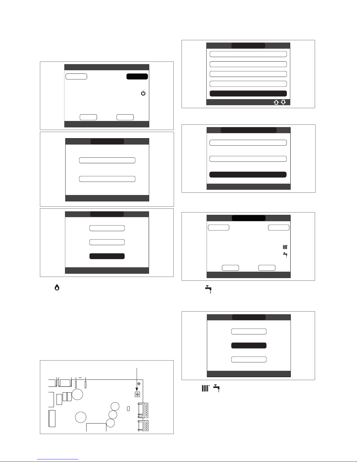
38
6.3 FIRST COMMISSIONING
- Carry out the procedure as detailed in section 6.1.
- Ensure that all services (gas, water, electricity) are supplied
and turned ON at the appliance.
- Ensure that the appliance has been set to WINTER (access
via STATE menu).
- Ensure that any time control and/or temperature control is
calling for heat.
18/05/2013 12:17
MENU
INFO SET
42
°C
1.3
bar
FRI
PLANT
HOT WATER TEMPERATURE
STATE
BOILER
STATE
MAIN ZONE
BOILER
OFF
SUMMER
WINTER
- When any heat request is generated and the burner is lit,
the “ ” icon appears on the display. The boiler will start
up and continue working until the set temperatures are
reached, after which it will then go back to standby.
VENT CYCLE FUNCTION
b
When the appliance is switched on for the first time or
whenever the electrical supply has been switched off
and then restored, an automatic vent cycle is carried out
lasting 2 min. When the vent cycle is in progress, all heat
requests are paused and a sliding message at the foot
of the page appears on the main page of the REC10.
In this condition the green and red LEDs are alternately
displayed every 0.5 second.
X17
X14
1
5
6
X6
1
3
1
X3
X7
arancione
E.R.
SW1
9
10
7
8
5
6
1
2
14
15
16
17
arancione (ES)
arancione (ES)
giallo (B)
nero (-)
rosso (+)
arancione (A)
(OT+)
(ES)
(TBT)
(RT)
+
-
A
B
REC
N
L
F= 3.15A F
230 V
M3
F
blu
marrone
TSC2
blu
EA
marrone
giallo/verde
N
F
X6
3
1
2
marrone
X15
blu
V Hv
1
2
1
4
2
3
verde A1)
rosso (A2)
arancione (K2)
bianco(K1)
J1
BE20
C.S.A.
marrone
blu
5
3
1
2
4
X4
combustion analysis button SW1
b
The vent cycle can be interrupted from the TECHNICAL
menu of the REC10:
- select VENT CYCLE with the “up” and “down” keys,
confirming the selection
TECHNICAL
INSTALLER
CALIBRATION
RANGE RATED
SWEEPER
THERMOREGULATION
VENT CYCLE
- select STOP FUNCTION with the “up” and “down” keys,
confirming the selection.
VENT CYCLE
STOP FUNCTION
INSTALLER
DISABLE FUNCTION
ENABLE FUNCTION
The REC10 will briefly display a wait message after which you
will automatically be taken to the main screen.
18/05/2013 12:17
INFO SET
30
°C
.3
MENU
FRI
STATE
PLANT
HOT WATER TEMPERATURE
1.3
bar
SUMMER : when the operating mode is set to SUMMER
(STATE>BOILER>SUMMER). The operating mode of the
appliance is set to HW only. The REC10 normally displays the
temperature of the domestic hot water supplied by the boiler.
BOILER
OFF
SUMMER
WINTER
WINTER / : when the operating mode is set to WINTER
(STATE>BOILER>WINTER). The operating mode of the
appliance is set to provide both heating and hot water.
NOTE
The main zone also needs to be set to ON (embedded clock
disabled) or AUTO/MANUAL (embedded clock enabled) in
order for the appliance to provide heating.
The UI will always display the current HW outlet temperature
unless a heating request is active. In this case, the flow outlet
temperature is displayed.
Page 39
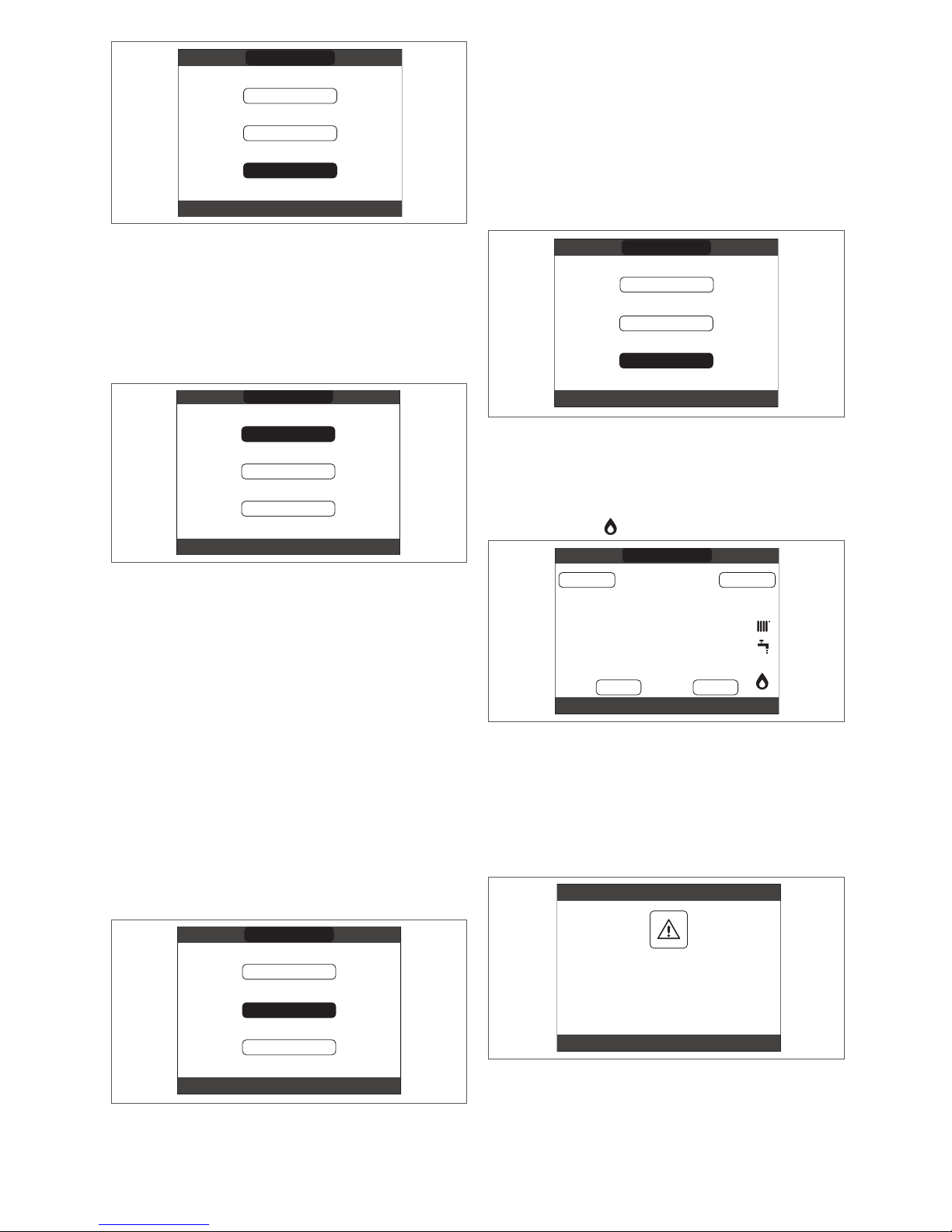
39
BOILER
OFF
SUMMER
WINTER
6.4 ADJUSTING THE HEATING WATER
TEMPERATURE WITHOUT AN OUTDOOR
TEMPERATURE SENSOR CONNECTED
When there is no outdoor temperature sensor, the boiler
operates at a fixed-point, the HEATING setpoint in this case
can be set selecting SET on the main screen of the REC10
and selecting the desired value within the range [40°C -
80.5°C] for high temperature systems or [20°C - 45 °C] for low
temperature systems (default is high temperature).
DHW
SET
PREHEATING
HEATING
6.5 ADJUSTING THE HEATING WATER
TEMPERATURE WITH AN OUTDOOR
TEMPERATURE SENSOR CONNECTED
When an outdoor temperature sensor is installed, the outlet
temperature is automatically selected by the system, which
quickly adjusts the ambient temperature according to the
variations in the outdoor temperature. If you want to change
the temperature, raising it or lowering it with respect to that
automatically calculated by the electronic board, it is possible
to change the HEATING setpoint by selecting SET on the
main screen of the REC10 and selecting within the range (-5
- +5) the desired comfort level (see section
“6.2.4 Setting the
thermoregulation”
).
Note: when there is an outdoor temperature sensor connected
it is still possible to have the boiler operate at a fixed point
setting the values of MIN SP HEAT and MAX SP HEAT at the
desired HEATING setpoint.
6.6 ADJUSTMENT OF THE DOMESTIC HOT
WATER TEMPERATURE
To adjust the domestic hot water temperature (bath, shower,
kitchen, etc.), set the DOMESTIC HOT WATER setpoint
selecting SET on the main screen of the REC10 and selecting
the desired value within the range [37.5°C - 60°C].
SET
HEATING
PREHEATING
DHW
6.7 “PREHEATING” FUNCTION
It is possible to access the PREHEATING function selecting
SET on the main screen of the REC10.
Setting PREHEATING = 1 the boiler’s domestic hot water
function activates. This function keeps the water in the
domestic hot water exchanger hot, to reduce standby times
when a request is made. When the preheating function is
enabled, the symbol P comes on with a steady light at the
top with respect to the hot water icon. During burner ignition
following a preheating request, the symbol P starts flashing.
To deactivate the preheating function, set the parameter to
PREHEATING = 0, the symbol “P” switches off.
The function is not active when the boiler is OFF.
SET
HEATING
DHW
PREHEATING
6.8 BOILER START-UP
In order to initiate a heating request, it is essential that any
time or temperature control is set to an ON period and at a
higher than current ambient temperature respectively.
The boiler will be in standby until the burner switches on
following a heat request.
The display shows “ ” to indicate the presence of a ame.
18/05/2013 12:17
MENU
INFO SET
42
°C
1.3
bar
FRI
PLANT
HOT WATER TEMPERATURE
STATE
During any heating request, the appliance will attempt to
reach and maintain the selected set point, at which point it will
modulate the fan speed to maintain the set outlet temperature.
Should the outlet temperature begin to exceed the set point,
the burner will switch off and the pump will continue to run.
In the unlikely event of a fault or malfunction occurring, the
appliance will enter a temporary or nal fault condition, during
which it shutdown; this is signalled via the UI by a warning
triangle and a short description of the fault. For further detailed
information on fault codes please refer to section 6.14.
E010
FLAME LOCKOUT
PRESS OK RESET
Page 40
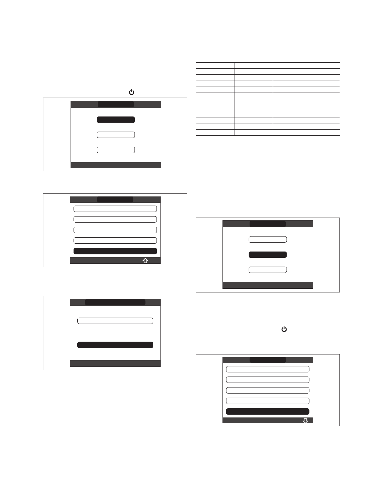
40
6.9 RESET FUNCTION
In the unlikely event of the appliance entering a fault condition;
use the arrow buttons on the UI to navigate to the warning
triangle, and press select. Then follow the instruction/advice
as shown on the UI screen.
b
If the release attempts do not restart the boiler, contact
the local Technical Assistance Centre.
6.10 SCREED HEATING FUNCTION
For a low temperature system the boiler has a “screed
heating” function that can be activated in the following way:
- set the status of the boiler to OFF
BOILER
OFF
SUMMER
WINTER
- select SCREED HEATING with the “up” and “down” keys,
confirming the selection (note: SCREED HEATING is not
available if the boiler is not OFF)
EXHAUST PROBE RESET
SCREED HEATING
TECHNICAL
INSTALLER
CALIBRATION
RANGE RATED
SWEEPER
- select ACTIVATE FUNCTION with the “up” and “down”
keys and confirm the selection to activate the function
- select DEACTIVATE FUNCTION with the “up” and “down”
keys and confirm the selection to deactivate the function.
SCREED HEATING
INSTALLER
DEACTIVATE FUNCTION
ACTIVATE FUNCTION
When the SCREED function is enabled, a scrolling
message is displayed on the lower part of the UI screen
SCREED HEATING FUNCTION IN PROGRESS - OUTLET
TEMPERATURE, while on the electronic board the red and
green LEDs flash alternately with a frequency of 1 sec ON - 1
sec OFF.
The “screed heating” function lasts 168 hours (7 days) during
which, in the zones configured as low temperature, a heating
request is simulated with an initial zone outlet of 20°C, then
increased in line with the table on the side.
Accessing the INFO menu from the main page of the REC10
it is possible to display the TIME FUNC SCREED HEATING
value regarding the number of hours since the start of the
function.
Once activated, the function takes priority, if the appliance
is shut down by disconnecting the power supply, when it is
restarted the function picks up from where it was interrupted.
The function can be interrupted before its end by putting the
appliance in a condition other than OFF or else by selecting
DEACTIVATE FUNCTION from the relative menu.
Note: The temperature and increase values can be set to
different values only by qualified personnel, only if strictly
necessary. The manufacturer declines all responsibility if the
parameters are incorrectly set.
DAY TIME TEMPERATURE
1 0 20°C
6 22°C
12 24°C
18 26°C
2 0 28°C
12 30°C
3 0 32°C
4 0 35°C
5 0 35°C
6 0 30°C
7 0 25°C
6.11 CHECKS DURING AND AFTER THE FIRST
COMMISSIONING
After start up, check that the boiler carries out the start-up
procedures and subsequent shut-down correctly.
Check the domestic hot water operation by opening a hot
water tap in SUMMER or WINTER mode.
NOTE
In order to perform a combustion analysis check, you should
ensure that the appliance is HOT; this can be achieved by
opening a hot water outlet and letting it run for several minutes:
- checking the combustion.
BOILER
OFF
SUMMER
WINTER
6.12 COMBUSTION CHECK
To carry out the combustion analysis, proceed as follows:
- ensure that the electrical supply to the appliance is switched
ON
- set the status of the boiler to OFF
- access the technical parameters as explained in section 8
- select SWEEPER with the “up” and “down” keys,
confirming the selection
THERMOREGULATION
PARAMETERS
RANGE RATED
CALIBRATION
SWEEPER
INSTALLER
TECHNICAL
NOTE
The dynamic gas pressure can be checked by attaching a
manometer to the test point located on the gas cock (please
also refer to 4.3).
Page 41
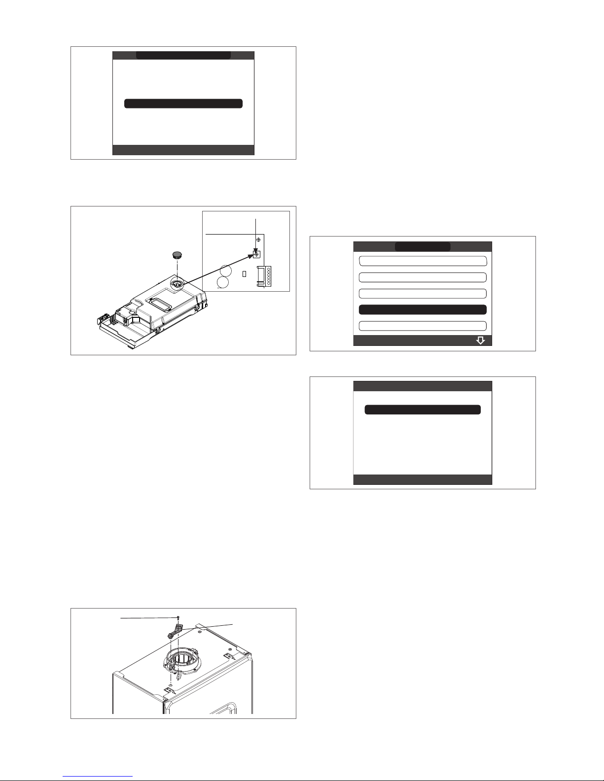
41
- select ACTIVATE FUNCTION with the “up” and “down”
keys, confirming the selection.
SWEEPER
INSTALLER
ACTIVATE FUNCTION
- Note: the sweeper function can also be activated by
pressing the SW1 key on the electronic board AKM (this
requires removing the plug (C) from the cover of the
instrument panel to access the electrical components).
X17
1
6
E.R.
SW1
9
10
7
8
5
612
14
15
16
17
nero (RT)
nero (RT)
rosa (OT+)
rosa (OT+)
arancione (ES)
arancione (ES)
6
1
1
2
5
1
rosso (+)
giallo (B)
arancione (A)
nero (-)
giallo (B)
nero (-)
rosso (+)
arancione (A)
bianco (TBT)
bianco (TBT)
(OT+)
(ES)
(TBT)
(RT)
+
-
A
B
REC
X11
X14
X25
TSC2
blu
EA
marrone
giallo/verde
N
F
X6
3
1
2
marrone
X15
blu
V Hv
1
2
1
4
2
3
verde A1)
rosso (A2)
arancione (K2)
bianco(K1)
J1
BE20
C.S.A.
marrone
blu
5
3
1
2
4
X4
combustion analysis button SW1
Wait for the burner to ignite.
The boiler will operate at maximum heating output and it will
be possible to check the combustion.
- Insert the analyser probes in the specific positions on the air
distribution box, after removing screw (A) and cap of the flue
gases analysis socket (B).
- Perform the combustion check verifying that the CO2 values
correspond to those indicated in section-2 “Technical Data”.
- Once completed, remove the analyser probe and close
the combustion analysis test points, using the previously
removed cap and screw.
b
Should the readings be signicantly different from the
values declared in the technical data table; do not
attempt to carry out any adjustment of the gas valve.
Please call the Vokera technical Helpline for assistance
and further advice.
b
The gas valve is non-adjustable and must not
be tampered with. Tampering with the gas valve
will result in the malfunction of the appliance and
possible damage to components.
b
When the sweeper function is in progress all the heat
requests are paused and a scrolling message appears
at the foot of the main page of the REC10; green and
red LEDs are off.
A
B
When the checks are completed:
- set the boiler to “SUMMER” or “WINTER” mode depending
on the User’s requirements
- regulate the heat request temperature values according to
the customer’s needs.
IMPORTANT
The sweeper function is active for a time limit of 15 minutes; the
burner shuts down if an outlet temperature of 95° C is reached. It
will ignite again when the temperature falls below 75° C.
b
In case of a low temperature system we recommend
carrying out the efciency test by taking hot water
setting the boiler STATE to SUMMER, opening the hot
water tap to full capacity and setting the temperature of
the domestic hot water to the maximum.
6.13 RANGE RATED
This appliance can be ‘range-rated’ if necessary, and this
function enables a bespoke maximum heat output to be set
according to the specic application:
- access the technical parameters as explained in section 8
- select RANGE RATED
PARAMETERS
RANGE RATED
THERMOREGULATION
TECHNICAL
INSTALLER
CALIBRATION
INSTALLATION
- set the desired heating maximum value (rpm) with the “up”
and “down” keys, confirming the selection
RANGE RATED
5100
RPM
- once the desired power is set (maximum heating) note
the value onto the supplied self-adhesive label. For further
checks and adjustments refer to the set value.
b
The calibration does not affect the boiler ignition.
The boiler is supplied with the settings indicated in the
technical data (section 2).
Nonetheless, it is possible to alter or limit the appliance
output, according to the system requirements or the regional
regulations on the combustion gas emission limits, to set that
value by referring to the graphs below.
Page 42
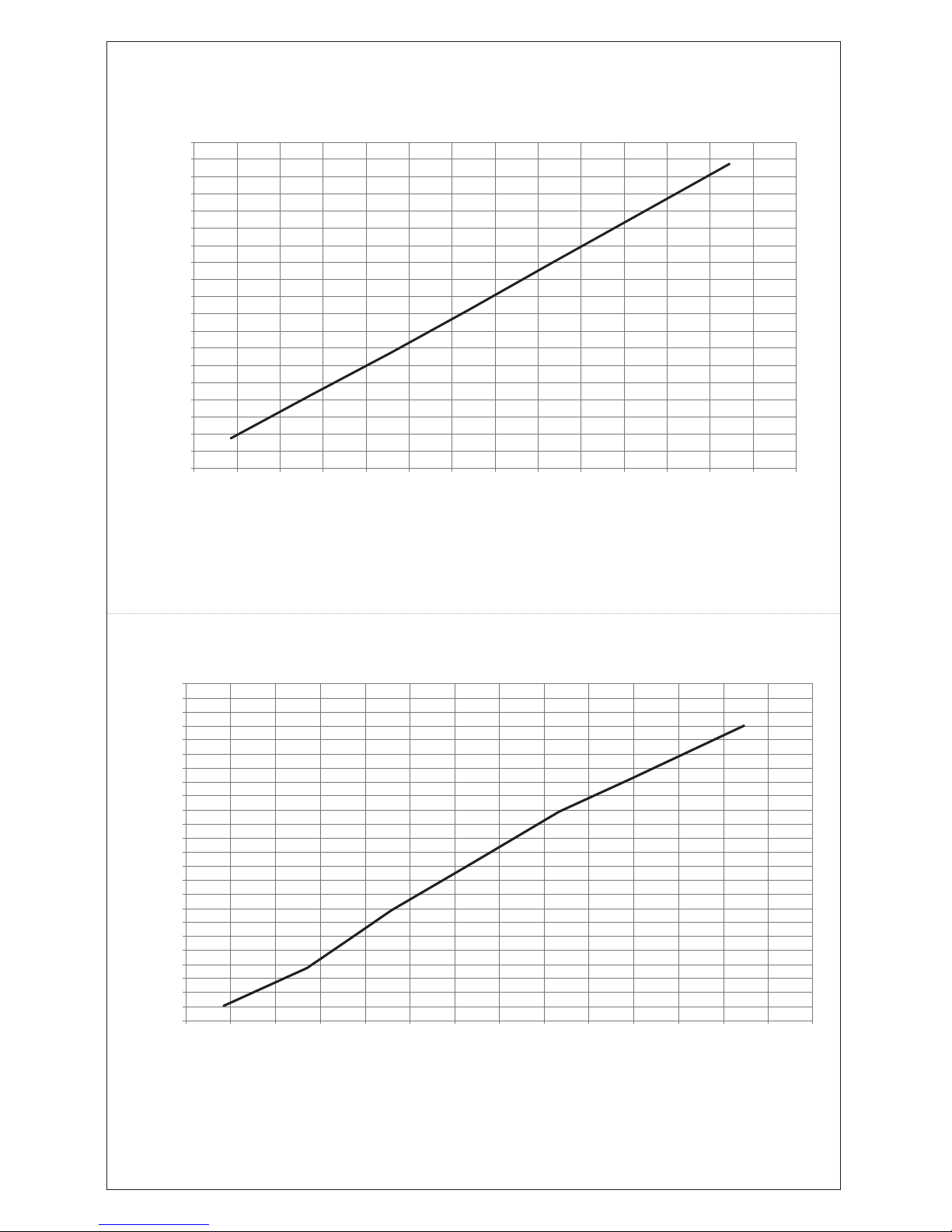
42
evolve 24C
Heat output (kW)
Fan rotations (rpm)
HTG curve (Qnheating)
800
1200
1600
2000
2400
2800
3200
3600
4000
4400
4800
5200
5600
6000
6400
6800
7200
7600
8000
8400
2 4 6 8 10 12 1 4 16 18 20 22 2 4 26 28 30
Curva portata termica - giri venlatore
Caldaia Vision+ 24C PLUS
0
10
20
30
40
50
60
70
80
90
1
00
1
10
1
20
1
30
1
40
1
50
1
60
1
70
1
80
1
90
2
00
2
10
2
20
2
30
2
40
2 4 6 8 1 0 12 14 16 18 2 0 22 24 26 28 3 0
Curva portata termica - emissioni CO
Caldaia Vision+ 24C PLUS
CO emissions s.a. (p.p.m.)
Heat output (kW)
CO s.a. curve (Qnheating)
Page 43
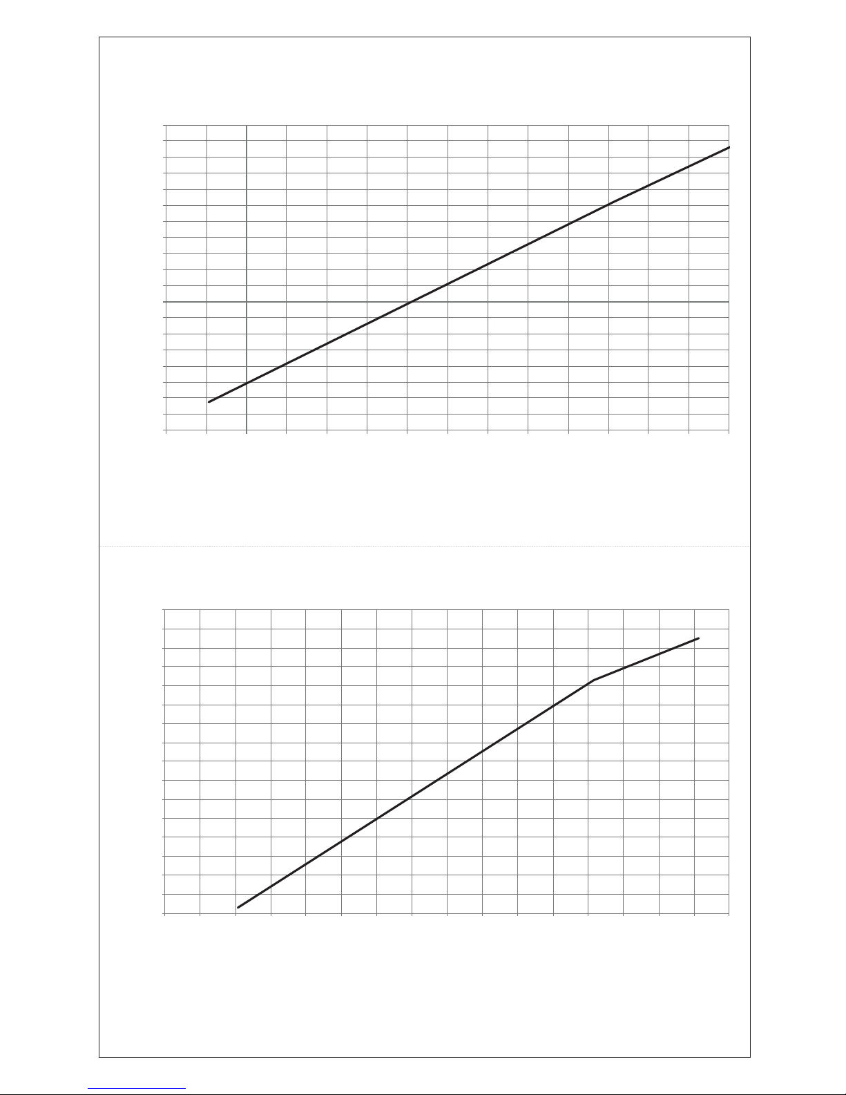
43
Heat output (kW)
Fan rotations (rpm)
HTG curve (Qnheating)
800
1200
1600
2000
2400
2800
3200
3600
4000
4400
4800
5200
5600
6000
6400
6800
7200
7600
8000
8400
2 4 6 8 10 12 14 1 6 1 8 20 22 24 26 2 8 3 0
Curva portata termica - giri venlatore
Caldaia Vision+ 28C PLUS
CO emissions s.a. (p.p.m.)
Heat output (kW)
CO s.a. curve (Qnheating)
0
10
20
30
40
50
60
70
80
90
100
110
120
130
140
150
160
0 2 4 6 8 10 12 14 16 18 20 22 24 26 28 30 32
Curva portata termica - emissioni CO
Caldaia Vision+ 28C PLUS
evolve 28C
Page 44
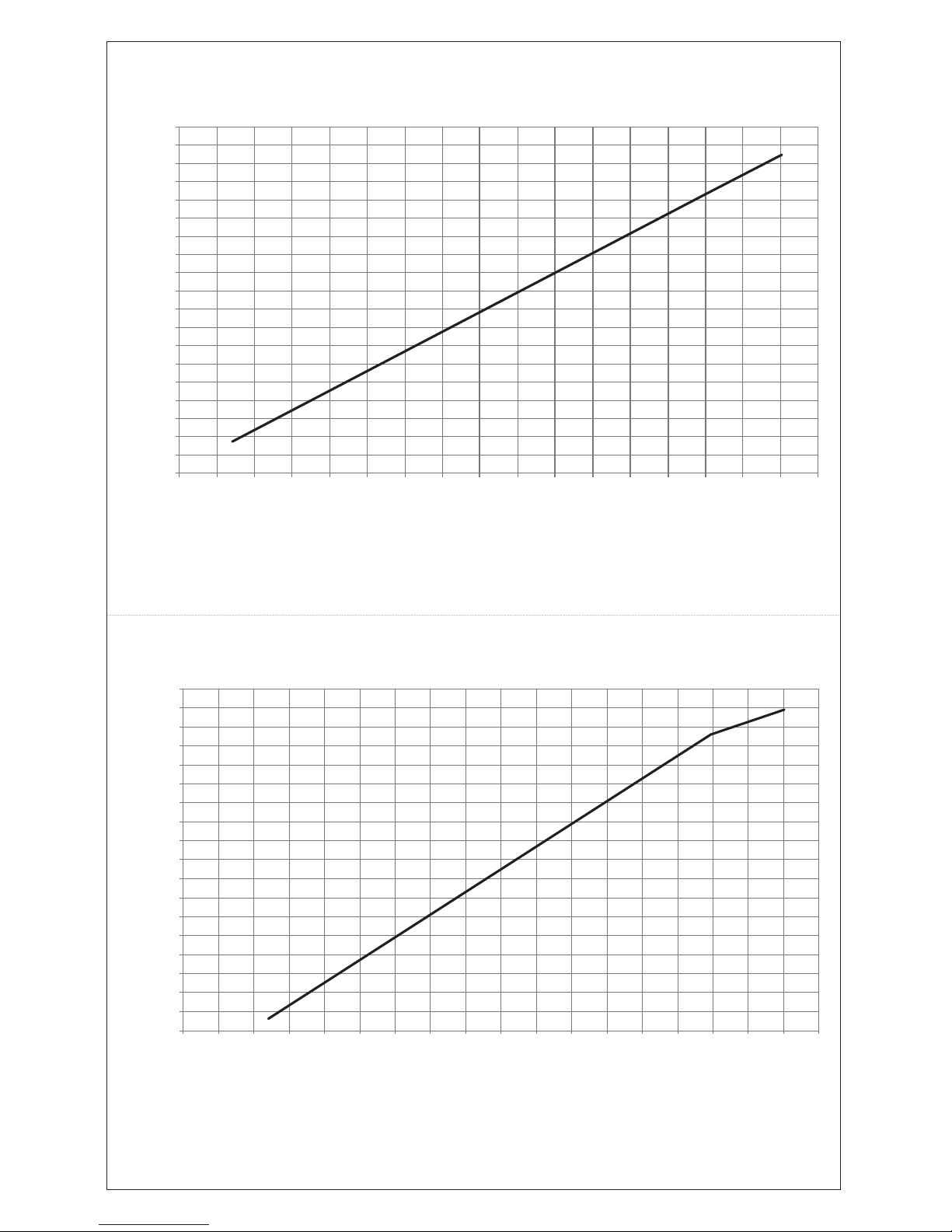
44
Heat output (kW)
Fan rotations (rpm)
HTG curve (Qnheating)
800
1
200
1
600
2
000
2
400
2
800
3
200
3
600
4
000
4
400
4
800
5
200
5
600
6
000
6
400
6
800
7
200
7
600
8
000
8
400
2 4 6 8 10 12 1 4 16 18 20 22 2 4 26 28 30 3 2 34 36
Curva portata termica - giri venlatore
Caldaia Vision+ 32C PLUS
CO emissions s.a. (p.p.m.)
Heat output (kW)
CO s.a. curve (Qnheating)
0
10
20
30
40
50
60
70
80
90
100
110
120
130
140
150
160
170
180
0 2 4 6 8 10 12 14 16 18 20 22 2 4 2 6 2 8 3 0 3 2 34 36
Curva portata termica - emissioni CO
Caldaia Vision+ 32C PLUS
evolve 32C
Page 45
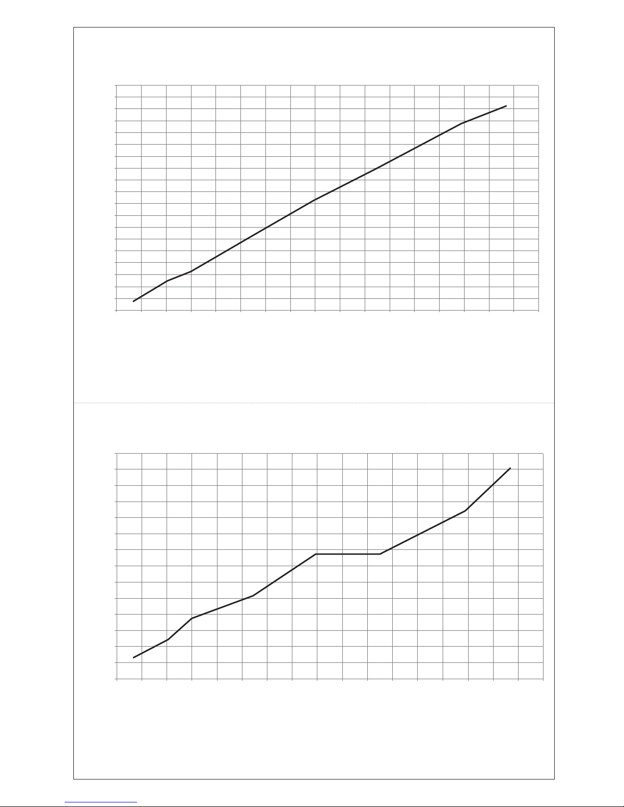
45
Heat output (kW)
Fan rotations (rpm)
HTG curve (Qnheating)
CO emissions s.a. (p.p.m.)
Heat output (kW)
CO s.a. curve (Qnheating)
evolve 36C
1200
1600
2000
2400
2800
3200
3600
4000
4400
4800
5200
5600
6000
6400
6800
7200
7600
8000
8400
8800
4 6 8 1 0 1 2 14 16 18 20 2 2 24 26 28 30 32 3 4 36 38
0
10
20
30
40
50
60
70
80
90
100
110
120
130
140
4 6 8 10 12 1 4 16 18 20 22 2 4 26 28 3 0 32 34 3 6 38
Page 46
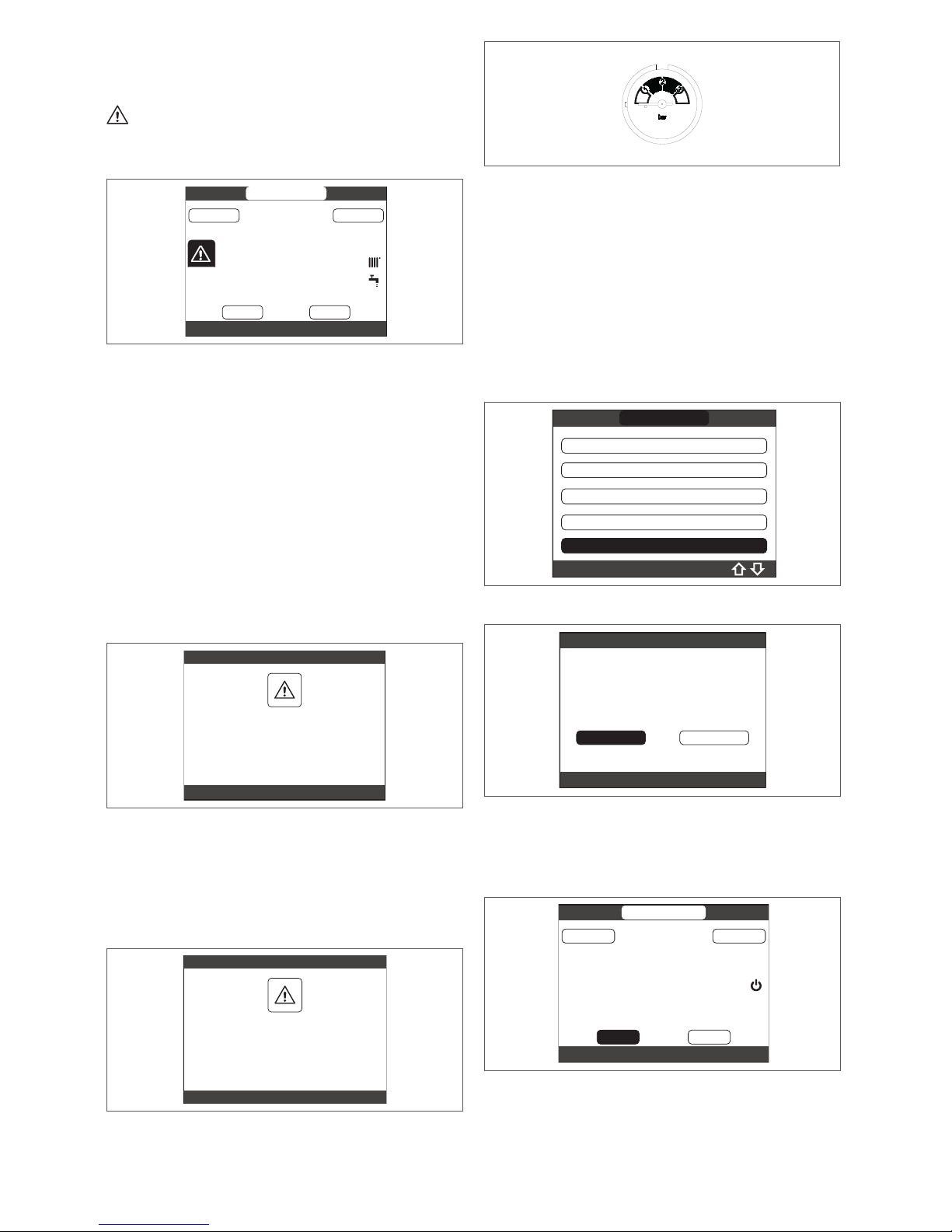
46
6.14 LIGHTS AND FAULTS
In the unlikely event of appliance malfunction and/or a
system fault, the appliance will enter a nal or temporary fault
condition, whereby it will shut down and a warning triangle
will appear on the left side of the UI screen. Use the arrow
buttons on the UI to navigate to the warning triangle, and
press select. Then follow the instruction/advice as shown on
the UI screen.
18/05/2013 12:17
MENU
INFO SET
42
°C
1.3
bar
FRI
PLANT
HOT WATER TEMPERATURE
STATE
The faults description screen is automatically displayed once
the display illumination time has elapsed without any button
being pressed.
Press the “up” and “down” keys to display the descriptions
of any other faults that may be present.
Reset function
In order to reset the boiler’s operation in the event of a
fault, it is necessary to access the fault description screen.
If the lockout is of a non-volatile type that requires a reset
procedure, this will be indicated on the screen, and can be
performed by pressing the “ok” button on the REC10.
At this point, if the correct operating conditions have been
restored, the boiler will restart automatically.
There are a maximum of 3 consecutive attempts at a release
by the REC10, should all 3 attempts at reset fail, the appliance
will require to be isolated briefly from the electrical supply
in order to carry out any further reset attempts. Once the
electrical supply supply has been restored, further attempts at
reset can be carried out.
b
E020
LIMIT THERMOSTAT
REC10 ATTEMPTS EXHAUSTED
If the attempts to reset the boiler are unsuccessful,
please contact the Vokera technical helpline.
For fault E041
If the pressure drops below the safety pressure limit of
0.3 bar the boiler displays the fault code “E041 - WATER
TRANSDUCER LOAD THE SYSTEM” for a transitional time
of 10 min during which it is possible to open the external lling
tap until the pressure is between 1 and 1.5 bar.
E041
WATER TRANSDUCER
LOAD THE SYSTEM
b
If the pressure drops frequently, contact your installer or
the Vokera customer care centre.
For fault E060
The boiler is working normally, but does not provide any
stability of the domestic hot water temperature that, in any
event, is supplied at a temperature of around 50°C. The
intervention of an engineer will be required.
For fault E091
The boiler has an auto-diagnostic system which, based on
the total number of hours in certain operating conditions, can
signal the need to clean the primary exchanger (alarm code
E091). Once the cleaning operation has been completed,
reset to zero the total hour meter with special kit supplied as
an accessory following procedure indicated below:
- access the technical parameters as explained in section 8
- select EXHAUST PROBE RESET with the “up” and
“down” keys, confirming the selection
TECHNICAL
INSTALLER
CALIBRATION
RANGE RATED
SWEEPER
THERMOREGULATION
EXHAUST PROBE RESET
- select CONFIRM to confirm the rest of the flue gases probe
meter or else CANCEL to cancel the operation
THE PARAMETER
WILL BE CHANGED
CONFIRM CANCEL
CONFIRM OR DELETE
SELECTION
NOTE: the meter resetting procedure should be carried out
after each in-depth cleaning of the primary exchanger or if
this latter is replaced.
The total hours can be verified in the following way:
- select INFO on the initial screen of the REC10 and press
“ok”
18/05/2013 12:17
MENU
INFO SET
30
°C
.3
FRI
PLANT
HOT WATER TEMPERATURE
STATE
1.3
bar
- with the “up” and “down” keys select EXHAUST PROBE
RESET and press “ok” to display the value of the flue
gases probe meter.
Page 47
47
Boiler faults list
ERROR
CODE
ERROR MESSAGE RED LED GREEN LED RED and GREEN
DESCRIPTION OF
ALARM TYPE
E010 ame lockout/ACF electronic fault ON nal
E011 extraneous ame
ashing
0.2 sec. on/0.2 off
transitional
E020 limit thermostat
ashing
0.5 sec. on/0.5 off
nal
E030 fan fault ON nal
E040 water transducer - check system water pressure ON nal
E041 water transducer - check system water pressure
ashing
0.5 sec. on/0.5 off
temporary
E042 water transducer fault ON nal
E060 domestic hot water probe fault
ashing
0.5 sec. on/0.5 off
temporary
E070
fault ow sensor
overtemperature ow sensor
ow/return sensor differential alarm
ON
temporary
nal
nal
E077 main zone water thermostat ON temporary
E080
fault return line probe
return line probe overtemperature
outlet/return line probe differential alarm
ON
temporary
nal
nal
E090
fault ue gases probe
ue gases overtemperature probe
ashing
0.5 sec. on/0.5 off
temporary
nal
E091 clean primary heat exchanger
ashing
0.5 sec. on/0.5 off
temporary
-- water pressure low - verify the system pressure
ashing
0.5 sec. on/0.5 off
temporary
-- water pressure high check system
ashing
0.5 sec. on/0.5 off
temporary
-- boiler board communication lost ON temporary
-- BUS 485 communication lost ON temporary
List of combustion faults
ERROR
CODE
ERROR MESSAGE
LED
RED
LED
GREEN
DESCRIPTION OF TYPE OF ALARM
E021 iono alarm ON
These are temporary alarms that if they occur 6 times in an hour they
become denitive; the alarm E097 is displayed and is followed by post-
purging for 45 seconds at the fan’s maximum speed.
It is not possible to release the alarm before the end of the post-purging
unless the boiler’s power supply is switched off.
E022 iono alarm ON
E023 iono alarm ON
E024 iono alarm ON
E067 iono alarm ON
E088 iono alarm ON
E097 iono alarm ON
E085 combustion fault/high CO ON
These are temporary alarms that if they occur 3 times in an hour they
become denitive; the last error to occur is displayed and is followed by a
post-purging of 5 minutes at the fan’s maximum speed.
It is not possible to release the alarm before the end of the post-purging
unless the boiler’s power supply is switched off.
E094 combustion fault/high CO ON
E095 combustion fault/high CO ON
E058 mains voltage fault ON
These are temporary faults that restrict the ignition cycle.
E065 current modulation alarm ON
E086 obstruction fumes alarm ON
Temporary fault reported during the post ventilation. It is maintained a post
ventilation of 5 min at maximum fan speed
Warning lights
BOILER STATUS RED LED GREEN LED RED and GREEN NOTES
Power-on
ashing
0.5 sec. on/0.5 sec. off
The red and green LEDs come on at the same
time
Vent cycle
ashing
0.5 sec. on/1 sec. off
ashing
0.5 sec. on/1 sec. off
The red and green LEDs come sequentially one
at a time
OFF status
ashing
0.3 sec. on/0.5 sec. off
No heat request (stby)
ashing
0.3 sec. on/0.5 sec. off
Transitional ignition/
overtemperature
ashing
0.3 sec. on/0.5 sec. off
Presence of ame ON
Chimney sweep ON Only if the ame is present
Screed heater
ashing
1 sec. on/1 sec. off
ashing
1 sec. on/1 sec. off
The red and green LEDs come on alternately
Page 48
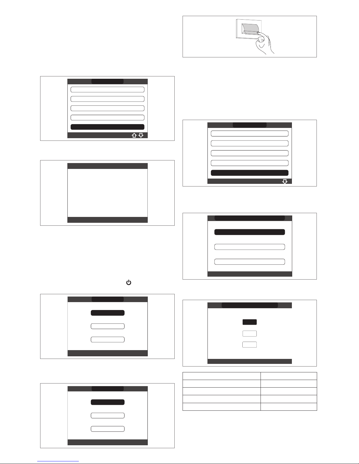
48
6.15 ALARM HISTORY
The ALARM HISTORY function is automatically enabled
only after the machine has been powered up for at least 2
consecutive hours, during this period of time any alarms that
arise would not be saved in the “alarm history”.
The alarms can be displayed in chronological order, from the
most recent to the oldest, up to a maximum of 50 alarms; to
display the alarm history:
- access the technical parameters as explained in section 8
- select ALARM HISTORY with the “up” and “down” keys,
confirming the selection
TECHNICAL
INSTALLER
CALIBRATION
RANGE RATED
SWEEPER
EXHAUST PROBE RESET
ALARM HISTORY
- scroll through the alarm history with the “up” and “down”
keys; for each alarms a sequential number is displayed, an
error code and the date and time the alarm occurred.
1 - 10:30 18/11/2013
E030
FAN ANOMALY
USE ARROW KEYS
TO SEE OTHER ANOMALIES
It is possible to return to the start page at any time by keeping
the “back” key pressed for at least 2 seconds.
Note: once enabled, the ALARM HISTORY function can no
longer be disabled; there is no procedure for resetting the
alarm history.
If an alarm repeats consecutively, it is saved only once.
6.16 TEMPORARY SWITCH-OFF
In the event of temporary absences (weekends, short breaks,
etc.) set the status of the boiler to OFF .
Refer to section 3.3 for further details.
BOILER
OFF
SUMMER
WINTER
6.17 SWITCHING OFF FOR LENGTHY PERIODS
Refer to section 3.4 for detailed advice on shutting down the
appliance for an extended period of time.
BOILER
OFF
SUMMER
WINTER
ON
OFF
6.18 COMBUSTION PARAMETERS
Although the parameters referring to the combustion control
system ACC (Active Combustion Control) are preset in the
factory, the simultaneous replacement of both electronics
boards (AKM and REC 10 MASTER) will require the reprogramming of these parameters.
- Access the technical parameters as explained in the section 8
- Select COMBUSTION MONITORING with the “up” and
“down” keys, confirming the selection
-
VENT CYCLE
PARAMETERS
EXHAUST PROBE RESET
ALARM HISTORY
COMBUSTION MONITORING
SERVICE
TECHNICAL
Select GAS TYPE
- Set this parameter depending on the type of gas of the
boiler. The values for this parameter are NG = NATURAL
GAS - LPG = LPG
COMBUSTION MONITORING
COMBUSTION OFFSET
BOILER TYPE
GAS TYPE
SERVICE
- Select BOILER TYPE
- Set this parameter depending on the type of boiler as shown
in the table
BOILER TYPE
A
C
SERVICE
B
BOILER TYPE
evolve 24C A
evolve 28C B
evolve 32C C
evolve 36C D
Page 49
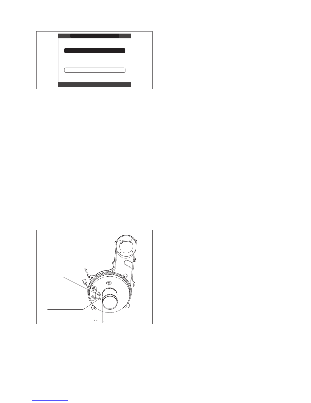
49
- Select COMBUSTION OFFSET
- Select RESTORE
- Press OK to confirm.
COMBUSTION OFFSET
RESTORE
RESET
SERVICE
6.19 MAINTENANCE
b
In case where, after the replacement of the electronic
board or the maintenance of the detection electrode or
the burner, the combustion analysis would restore out of
tolerance values, it may be necessary to take action on
the parameter COMBUSTION OFFSET as described in
the section
“6.18 Combustion check parameters”
.
Note: in case of replacement of the electrode, slight
variations of the combustion parameters can not be
excluded. These data wil return to nominal values after
a few hours of operation.
b
Do not clean the appliance or its parts with inammable
substances (e.g. petrol, alcohol, etc.).
b
Do not clean panels, painted parts and plastic parts with
paint thinner.
b
Panel cleaning must be carried out only with soapy
water.
Maintenance of the combustion control system
Maintenance electrode
The detection electrode/ionization sensor has an important
function in the boiler ignition phase and in the maintenance of
a proper combustion; in this context, in case of replacement,
it is necessary to always ensure that it is correctly positioned
and to strictly observe the reference shown in the gure.
ame detection electrode/
ionization sensor
ame
ignition electrode
a
Do not clean the electrode with sandpaper or any other
abrasive material.
b
The ‘Iono’ electrode will degrade over a over a period
of time and continued usage; it is therefore strongly
recommended that it be replaced after 5-years of use; in
order to ensure continued performance and efciency,
and avoid appliance malfunction.
6.20 FINAL CHECKS
• ENSURE THE APPLIANCE FLUE SYSTEM IS FITTED
CORRECTLY AND IS PROPERLY SECURED.
• ENSURE ALL PIPE WORK IS RE-CHECKED FOR
TIGHTNESS.
• COMPLETE BENCHMARK CHECKLIST.
FOR UK ONLY
Complete details of the boiler, controls, installation and
commissioning in the Benchmark checklist at the back of this
book. It is important that the Benchmark checklist is correctly
completed and handed to the user. Failure to install and
commission the appliance to the manufacturers instructions
will invalidate the warranty.
6.21 INSTRUCTING THE USER
Hand over all documentation supplied with this appliance –
including these instructions – and explain the importance of
keeping them in a safe place.
Explain to the user how to isolate the appliance from the gas,
water and electricity supplies and the locations of all drain
points. Show the user how to operate the appliance and any
associated controls correctly.
Show the user the location of the lling valve and how to top-
up the system pressure correctly and show the location of all
manual air release points.
Explain to the user how to turn off the appliance for both long
and short periods and advise on the necessary precautions to
prevent frost damage.
Explain to the user that for continued safe and efcient operation,
the appliance must be serviced annually by a competent person.
IMPORTANT
To validate the appliance warranty, it’s necessary to register
the appliance details with us. The warranty can be registered
in several ways:
• online at: vokera.co.uk
• for UK residents by calling: 0800 479 0751
• for ROI residents by calling: 056 7755055.
Page 50

50
7.1 GENERAL
Once the appliance has been serviced, the benchmark Service
Record must be completed.
For UK only
It is important that the Benchmark Service Record is correctly
completed and handed to the user. Failure to install and
commission the appliance to the manufacturers instructions
will invalidate the warranty.
To ensure the continued safe and efcient operation of the
appliance, it is recommended that it is checked and serviced
at regular intervals. To ensure correct and safe operation of the
appliance, it is essential that any worn or failed component be
replaced only with a genuine Vokèra spare part. It should be
remembered that although certain generic components may
look similar, they will be specic to an individual appliance
or product range. Use of non-genuine Vokèra spare parts
could invalidate your warranty and may pose a potential
safety hazard. The frequency of servicing will depend upon
the particular installation conditions, but in general, once per
year should be sufcient. It is the law that any servicing work
is carried out by competent person such as a Vokèra engineer,
an approved service agent, British Gas, GAS SAFE registered
personnel or other suitably qualied personnel. The following
instructions apply to the appliance and its controls, but it should
be remembered that the central heating and the domestic hot
water systems would also require attention from time to time.
7.2 ROUTINE ANNUAL MAINTENANCE
The appliance incorporates many ‘state-of-the-art’
components that are either ‘solid-state’ or are regarded as
‘non-serviceable’ items. As a consequence, the requirements
for routine annual maintenance are focussed upon:
1. ensuring that the appliance and ue system are in a safe
condition
2. ensuring that the appliance is operating safely
3. ensuring that the appliance is performing to its design
specication.
When the appliance has been installed to within the minimum
stated clearances; the appliance layout is such that it enables
routine annual maintenance to be carried out entirely from the
front of the appliance.
NOTE
Any noticeable defect or deterioration on or within the
appliance and ue system that impacts or affects the above
requirements; will warrant further diagnosis and repair, which
may result in the replacement of components.
Specic advice and instruction on the removal and replacement
of component parts of the appliance can be found in the
following pages of this section.
7.2.1 ROUTINE ANNUAL MAINTENANCE
REQUIREMENTS
1. Check the operation of the appliance in both the heating
and hot water modes and ensure the performance is in line
with the appliance specication.
2. Using the UI menu, navigate to the alarms history and
check for any recent alarm events (menu string is:
MENU>SETTINGS>TECHNICAL>ALARM HISTORY).
Refer to the alarm/fault codes description chart for further
information.
3. Remove the front cover (see 5.7.1) and visually inspect the
internal components and electrical wiring for any defect or
deterioration.
4. Visually check for any dirt or debris within the condensate
trap (the trap is translucent and can be checked visually).
5. Replace the front cover as detailed in 5.7.1 taking notice of
the importance of ensuring that the effectiveness of the –
front cover – seals are not compromised.
6. Carry out a combustion analysis as detailed in 6.12.
7. Visually check the entire ue system for any damage, defect,
or deterioration.
NOTE
In order to access the ‘alarms history’ it is necessary to access
the password protected settings. Refer to section 8 for further
details.
SECTION 7 - SERVICING INSTRUCTIONS
7.2.2 UNSCHEDULED MAINTENANCE
The appliance incorporates software that monitors the
operating conditions of the appliance, and will record any
‘unusual usage conditions’ that will affect the requirement to
remove and clean the burner/heat exchanger assembly. When
the ‘unusual usage’ hours reach a pre-determined threshold,
the appliance will signal – via alarm code E091 – that the heat
exchanger requires to be cleaned.
7.3 REPLACEMENT OF COMPONENTS
Although it is anticipated that this appliance will provide years of
trouble-free service and outstanding performance; the lifespan of
any component will be determined by factors such as operating
conditions and usage levels. Should the appliance develop a
fault, the fault-nding section of this manual will greatly assist
in determining the cause; however further advice can be sought
from the Vokera Technical Help-line. Remember always to use
only genuine Vokera spare parts.
7.4 COMPONENT REMOVAL PROCEDURE
To remove/replace a component, access to the interior of the
appliance is usually essential.
Always isolate the appliance from the electrical supply – and
if necessary remove the fuse.
• Close all service valves if any hydraulic and/or gas carrying
item is to be removed.
• Remove the front cover – and where necessary or
convenient – the side panels of the appliance as detailed in
5.7.1.
• If required, drain the primary circuit via the drain valve
(located adjacent to the diverter valve) using the tubing
supplied with the appliancee.
• If required, drain the secondary circuit via the available DHW
outlets.
NOTE
When removing a hydraulic component, ensure that some
water absorbent cloths are available to catch any residual
water that may drip from the appliance and/or the removed
component.
When the appliance has been installed to within the stated
minimum clearances; it may be necessary to remove
adjacent components in order to facilitate access to a specic
component.
Carry out the relevant elements of the commissioning
procedure (section 6.3) after replacing a component.
ALWAYS TEST FOR GAS TIGHTNESS IF ANY GAS
CARRYING COMPONENT HAS BEEN DISTURBED,
REMOVED, OR REPLACED.
WHEN REPLACING THE SIDE PANELS AND/OR THE
FRONT COVER, ENSURE THE ROOM SEALED INTEGRITY
OF THE APPLIANCE HAS NOT BEEN COMPROMISED –
REFER TO 5.7.1.
7.4.1 APPLIANCE PCB
Carry out the component removal procedure as outlined in 7.4.
Remove the appliance PCB cover as detailed in 5.7.3.
TO REMOVE AND REPLACE THE APPLIANCE PCB
Remove the 4-screws – located at each corner of the PCB
– that secure the PCB to the rear of the control panel.
Remove the screws and store them safely. Take note of the
corresponding locations where each of the wiring plugs and
terminals are connected to on the PCB, and then carefully
remove each plug/terminal. Replace the PCB in the reverse
order and ret the securing screws and PCB cover. Ret the
front cover as detailed in 5.7.1.
NOTE
If a new PCB has been installed, the appliance conguration
will need to be uploaded onto the new PCB from the REC10
UI. Therefore at start-up, the UI screen will request selection
of the conguration type:
• from AKM
• from REC10.
Use the up/down buttons to highlight ‘REC10’ and press select
(for detailed advice on this, refer to section 7.4.26).
Page 51
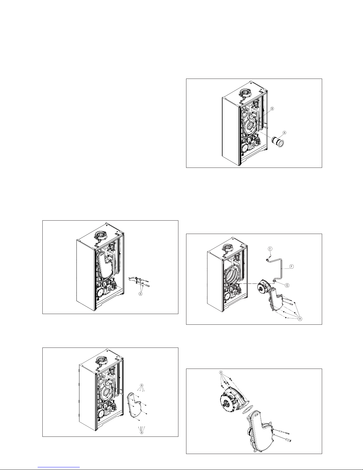
51
7.4.2 REC10 USER INTERFACE (UI)
Carry out the component removal procedure as outlined in 7.4.
Remove the appliance PCB cover as detailed in 5.7.3.
TO REMOVE AND REPLACE THE REC10
Locate and remove the 2-screws that secure the REC10 to
its aperture. From the front of the control panel, gently lever
out the REC10 from its sealing aperture; and once removed,
disconnect the wiring plug from the REC10. Replace the
REC10 in the reverse order and ret the securing screws and
PCB cover. Ret the front cover as detailed in 5.7.1.
NOTE
If a new REC10 has been installed, the appliance conguration
will need to be uploaded onto the new REC10 from the
appliance PCB. Therefore at start-up, the UI screen on the
REC10 will request selection of the conguration type:
• from AKM
• from REC10.
Use the up/down buttons to highlight ‘AKM’ and press select
(for detailed advice on this, refer to section 7.4.25).
NOTE
If both REC10 and appliance PCB are replaced simultaneously,
refer to the detailed guidance provided in section 8.8 and 6.18,
on how to set up a new appliance conguration.
7.4.3 ELECTRODE ASSEMBLIES
Carry out the component removal procedure as outlined in 7.4.
Remove the front cover as detailed in 5.7.1.
Disconnect the electrode from its wiring connector.
Each electrode assembly is retained by two securing screws
(A); remove both securing screws from the relevant electrode
assembly and carefully withdraw the electrode from its location
– taking extreme care not to damage or bend the electrode in
the process.
Replace in the reverse order.
NOTE
Any damage or deterioration to the electrode seal will require
it to be replaced with a new seal.
7.4.4 AIR/GAS CONVEYOR COVER
Carry out the component removal procedure as outlined in 7.4.
Remove the front cover as detailed in 5.7.1.
Remove securing screws (A).
Replace in the reverse order.
NOTE
Any damage or deterioration to the seal will require it to be
replaced with a new seal.
7.4.5 BURNER
Carry out the component removal procedure as outlined in 7.4.
Remove the front cover as detailed in 5.7.1.
Remove air/gas conveyor cover as detailed in 7.4.4.
Locate and remove cylindrical burner (A).
Replace in the reverse order ensuring that the seal (B) is
correctly located, and that the burner (A) is also correctly
located (both the seal and the burner incorporate a ‘notch’
that must be in alignment with the corresponding tab of the
burner aperture).
Ret air/gas conveyor cover as detailed in 7.4.4.
7.4.6 FAN & MIXER ASSEMBLY
Carry out the component removal procedure as outlined in 7.4.
Remove the front cover as detailed in 5.7.1.
Disconnect wiring from fan.
Disconnect electrode leads.
Disconnect outlet gas pipe (F) from the gas valve loosen nut
(G), and remove locking pin (E) that secures the pipe to the
fan mixer.
Loosen the 4 screws (H). The entire fan mixer assembly can
now be removed. Replace in the reverse order ensuring any
worn or damaged seals are replaced with new ones.
7.4.7 FAN REMOVAL
Carry out the component removal procedure as outlined in 7.4.
Remove the front cover as detailed in 5.7.1.
Remove the fan and mixer assembly as detailed in 7.4.6.
Remove the 4-hex screws (A) that secure the fan to the air/
gas mixer assembly. Replace in the reverse order ensuring
any worn or damaged seals are replaced with new ones.
Page 52
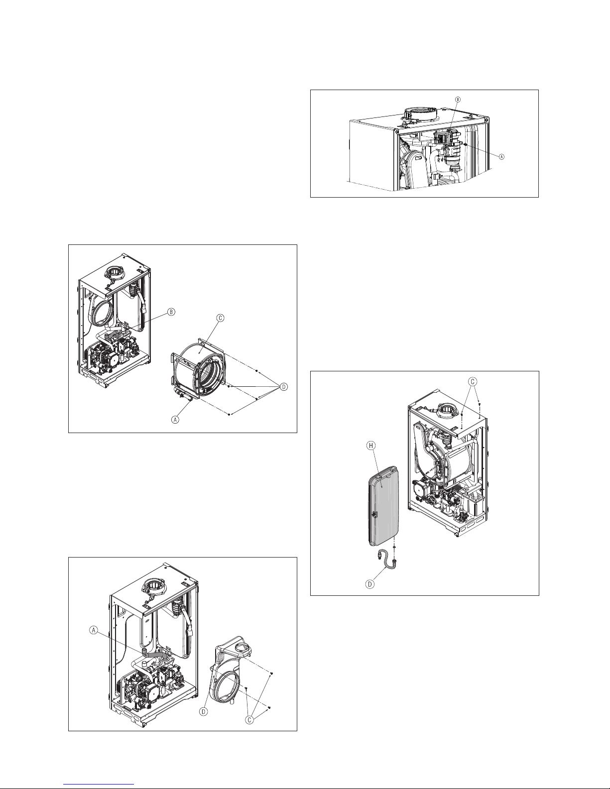
52
7.4.10 IGNITION TRANSFORMER
Carry out the component removal procedure as outlined in 7.4.
Remove the front cover as detailed in 5.7.1.
Disconnect wiring from ignition transformer (B).
Locate and remove securing screw (A).
Replace in the reverse order.
7.4.11 EXPANSION VESSEL
Carry out the component removal procedure as outlined in
7.4, paying special attention to the possibility of some residual
water still remaining within the vessel (with the appliance drain
still open, it is possible to displace most of the residual water
in the vessel by attaching a pump to the valve on the vessel
and pump it out via the drain).
Remove the front cover as detailed in 5.7.1.
Disconnect the exible expansion pipe (D) from the bottom of
the expansion vessel (H).
Locate and remove the top rear securing screw (C).
Locate and remove the front securing screw (C).
The vessel can now be lifted out of its lower retaining bracket.
Replace in the reverse order, ensuring that the vessel’s charge
pressure is correct and that any worn or damaged seals are
replaced with new ones.
7.4.12 DHW FLOWMETER
Carry out the component removal procedure as outlined in 7.4.
Remove the front cover as detailed in 5.7.1.
Disconnect the electrical plug from the owmeter (C).
Disconnect pipe (B) from the owmeter outlet and place the
ow-restrictor (D) to the side.
Locate and withdraw the locking pin that secures the owmeter
body to the lower frame of the appliance and lift the owmeter
away.
Replace in the reverse order ensuring any worn or damaged
seals are replaced with new ones.
7.4.8 PRIMARY HEAT EXCHANGER
Carry out the component removal procedure as outlined in 7.4.
Remove the front cover as detailed in 5.7.1.
Disconnect wiring to fan.
Detatch the wiring from the clip on the left rear side of the
exchanger.
Disconnect electrode leads.
Loosen the 2 screws (C) and disconnect and/or remove ow
pipe (D) from cyclonic separator as detailed in 7.4.6.
Disconnect return pipe (A) from pump outlet.
Disconnect and remove outlet gas pipe (F) as detailed in 7.4.6.
Disconnect condensate pipe (B) from the bottom of the
exchanger (C).
Locate and remove the 4-securing screws (D) that secure the
exchanger to the appliance back frame.
Gently withdraw the entire fan/mixer & heat exchanger
assembly from the appliance.
Carefully replace the assembly in the reverse order paying
attention to aligning the rear outlet of the exchanger with the
corresponding inlet of the ue gas conveyor and ensuring no
pipes or wiring is trapped between the exchanger and the
appliance back frame.
Replace any worn or damaged seals where necessary.
7.4.9 FLUE GAS CONVEYOR
Carry out the component removal procedure as outlined in 7.4.
Remove the front cover as detailed in 5.7.1.
Remove the fan/mixer & heat exchanger assembly as detailed
in 7.4.8.
Disconnect tubing from the top AAV at the conveyor.
Disconnect the condensate tubing (A) from the bottom of the
conveyor (D).
Locate and remove the 3-securing screws (C) and withdraw
the conveyor.
Replace in the reverse order ensuring any worn or damaged
seals are replaced with new ones.
Page 53
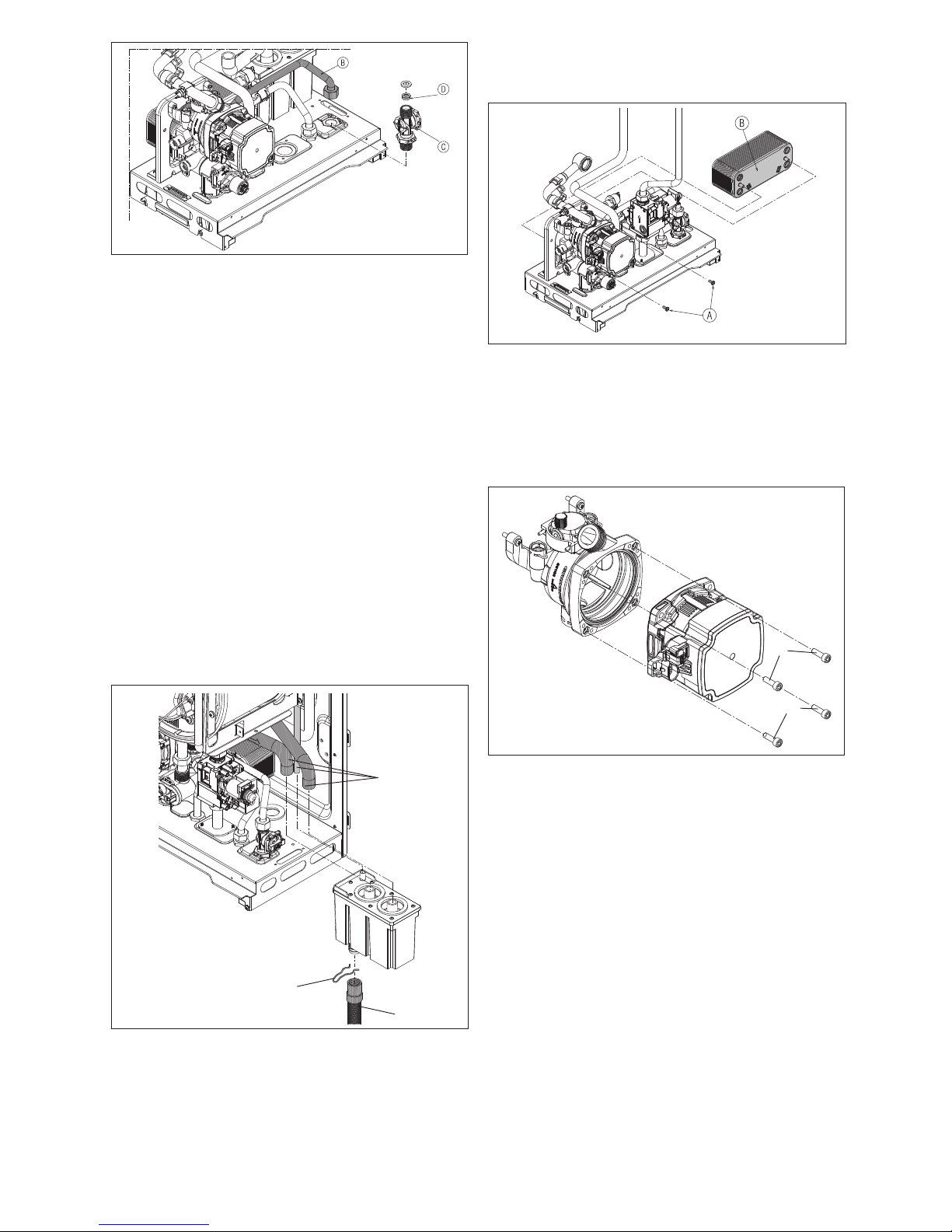
53
Replace in the reverse order ensuring that the 4-ports of the
heat exchanger are correctly aligned with the corresponding
ports of the hydraulic manifolds. Replace any worn or
damaged seals with new ones.
7.4.15.1 PUMP HEAD
Carry out the component removal procedure as outlined in 7.4.
Remove the front cover as detailed in 5.7.1.
Disconnect both electrical plugs on the pump head.
Unscrew the 4 retaining screws (A) that secure the pump
head to the pump body (use a 4mm allen key or t-bar) and
remove the pump head.
Replace in the reverse order.
A
A
7.4.15.2 LOWER AAV
Carry out the component removal procedure as outlined in 7.4.
Remove the front cover as detailed in 5.7.1.
Locate and remove the locking pin (B) that secures the exible
expansion pipe to the pump body; then remove the pipe from
its aperture.
Locate and pull out locking pin (G) until it touches the edge of
the safety valve pipe.
Apply rm pressure around the AAV (H) in order to free it from
its aperture within the pump body.
Replace in the reverse order ensuring that the AAV is
orientated as shown in the diagram; and ensure that the AAV
is fully inserted and clicks into it’s aperture. NOTE: the locking
pin for the exible expansion pipe can only be inserted one
way, with the straight leg to the right.
Replace any worn or damaged seals with new ones.
7.4.15.3 PUMP ASSEMBLY
Disconnect the return pipe from the pump outlet.
Disconnect the electrical plugs from the pump head.
Extract the locking pin (E) from the base of the pump body (F).
Remove locking pin (B) from the top right of the pump body.
Locate and remove securing screws (D).
Gently lift the pump assembly upwards then outwards, then
remove locking pin (C) from the top left of the pump body,
before removing the assembly from the appliance.
Replace in the reverse order.
Replace any worn or damaged seals with new ones.
7.4.13 CONDENSATE TRAP
Carry out the component removal procedure as outlined in 7.4.
Remove the front cover as detailed in 5.7.1.
The condensate trap can be removed from the right hand side
if/when there is a minimum of 50mm clearance to the side of
the appliance. This method of removal is signicantly quicker.
The following method of removal assumes that there is
insufcient clearance to the right-side of the appliance.
NOTE
Ensure that the appliance/components are protected from
any residual water that may still remain within the expansion
vessel.
Disconnect the gas valve as detailed in 7.4.21. (NOTE: it is
not necessary to remove the electrical wiring to the gas valve),
and move it to the side.
Disconnect the DHW pipe at the outlet of the DHW owmeter.
Disconnect the exible pipe from the bottom of the expansion
vessel.
Disconnect the three rubber tubes (A) that are connected to
the condensate trap.
Disconnect pipe (C) that is connected to the condensate outlet
(located beneath the appliance).
Remove the locking pin (B) at the condensate outlet that
secures the condensate trap to the lower frame of the
appliance.
The condensate trap can now be lifted and removed from its
location.
Replace in the reverse order, ensuring any worn or damaged
seals are replaced with new ones.
A
B
C
7.4.14 DHW HEAT EXCHANGER
Carry out the component removal procedure as outlined in 7.4.
Remove the front cover as detailed in 5.7.1.
Remove the condensate trap as detailed in 7.4.13.
Locate and unscrew both securing screws (A).
Move the heat exchanger (B) sideways to the right and then
lift it out from the appliance (NOTE: the heat exchanger can
only be tted in one way; pay attention to its orientation when
you are removing it, and ensure that it’s replaced in the exact
same way).
Page 54
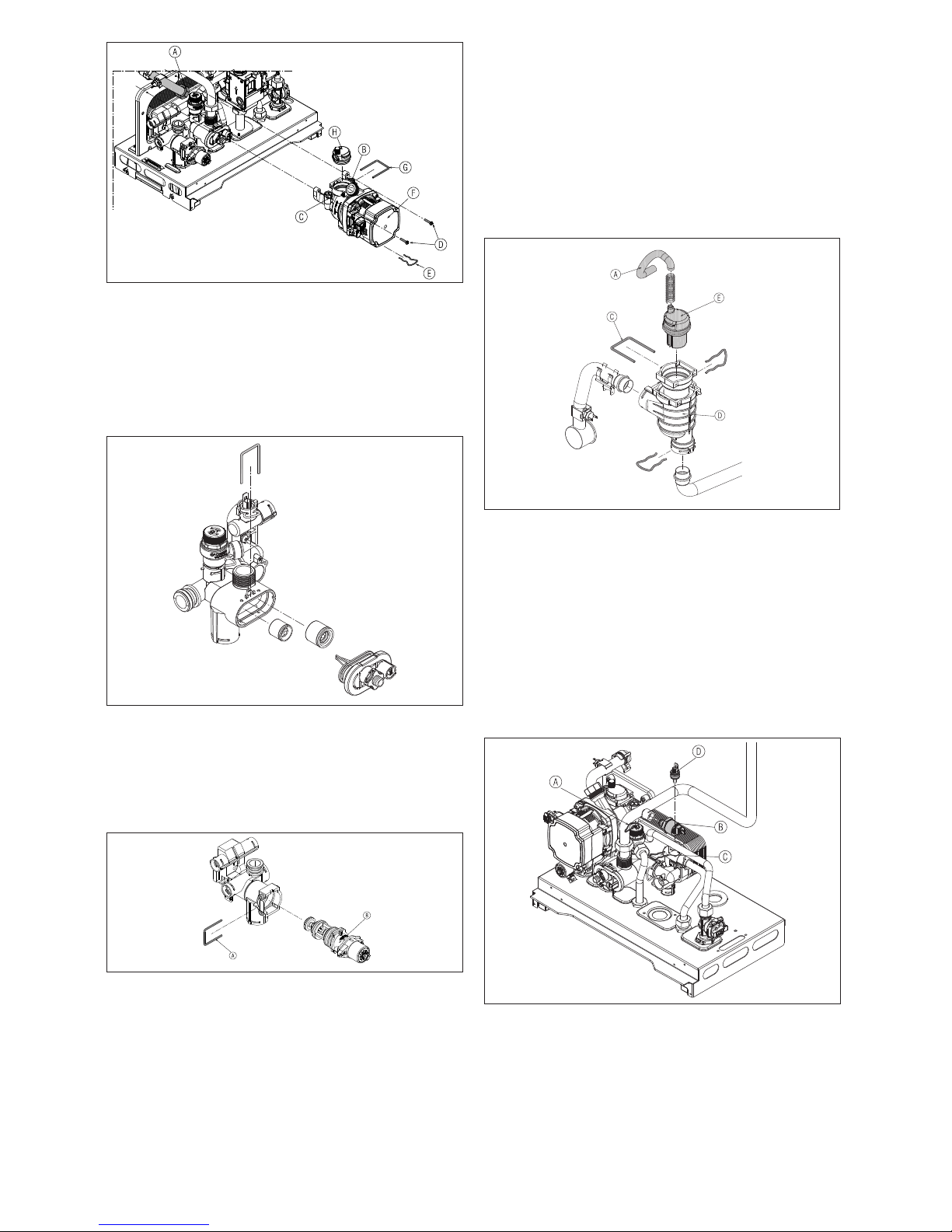
54
7.4.16 BYPASS/NON RETURN VALVE
Carry out the component removal procedure as outlined in 7.4.
Remove the front cover as detailed in 5.7.1.
Remove locking pin as shown in the diagram.
Using a hooked piece of wire or similar; insert the hook into
the AB and/or NRV and engage the hook in order to extract
the item/s.
Replace in the reverse order; ensuring that any worn or
damaged seals are replaced with new ones.
7.4.17 DIVERTER VALVE CARTRIDGE
Carry out the component removal procedure as outlined in 7.4.
Remove the front cover as detailed in 5.7.1.
Remove locking pin (A) and extract the complete cartridge/
actuator assembly (B).
Replace in the reverse order ensuring correct orientation and
alignment.
7.4.18.1 DEGASSING UNIT
Carry out the component removal procedure as outlined in 7.4.
Remove the front cover as detailed in 5.7.1.
Detach the rubber tube (A) that connects to the AAV (E).
Locate and remove the locking pin (C).
Using rm steady pressure, extract the AAV from its aperture
Replace in the reverse order.
NOTE: The AAV must be inserted as shown in the diagram.
The rubber O’ring seal should be placed over the AAV and
smeared with some silicone grease. The AAV should ‘click’
when correctly inserted into its aperture.
7.4.18.2 CYCLONIC SEPERATOR
Carry out the component removal procedure as outlined in 7.4.
Remove the front cover as detailed in 5.7.1.
Remove both locking pins that secure the inlet and outlet
pipes to the separator (D).
Slacken - but do not remove - both screws that secure the
outlet pipe on the main heat exchanger (allowing the pipe to
rotate freely).
Gently prize apart the inlet/outlet pipes from the separator
until it is free.
Detach the rubber tube (A) that connects to the AAV.
Replace in the reverse order ensuring that any worn or
damaged seals are replaced with new ones.
7.4.19.1 PRESSURE TRANSDUCER
Carry out the component removal procedure as outlined in 7.4.
Remove the front cover as detailed in 5.7.1.
Locate and remove locking pin (A).
Remove transducer (B).
Disconnect plug from transducer.
Replace in the reverse order.
7.4.19.2 DHW SENSOR
Carry out the component removal procedure as outlined in 7.4.
Remove the front cover as detailed in 5.7.1.
Locate and remove locking pin (C).
Remove sensor (D).
Disconnect plug from sensor.
Replace in the reverse order.
Page 55
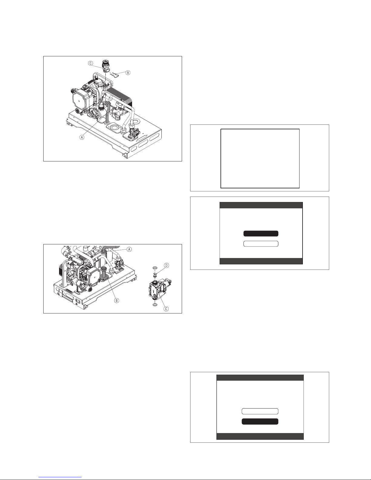
55
7.4.20 SAFETY VALVE
Carry out the component removal procedure as outlined in 7.4.
Remove the front cover as detailed in 5.7.1.
Disconnect safety valve outlet pipe (A) from the safety valve.
Locate and remove locking pin (B) and then extract safety
valve (C) from its aperture.
Replace in the reverse order.
7.4.21 GAS VALVE
Carry out the component removal procedure as outlined in 7.4.
Remove the front cover as detailed in 5.7.1.
Slacken off both inlet and outlet nuts (A&B).
Swivel the gas valve (C) round and disconnect the electrical
connections.
Unscrew both A&B completely in order to remove the gas
valve.
Remove the nozzle (D) for use with a replacement valve if the
gas valve is to be replaced.
Replace in the reverse order.
NOTE: the gas valve is a non-serviceable item - DO NOT attempt to alter or adjust any of its mechanical settings. Both
sealing washers must be replaced.
7.4.22 DRY CONTACT SENSORS (FLOW, RETURN,
HI-LIMIT)
Carry out the component removal procedure as outlined in 7.4.
Remove the front cover as detailed in 5.7.1.
Identify the sensor to be replaced.
Remove the pipe clip that incorporates the sensor from its
location.
Disconnect both wires from the sensor.
Remove the sensor from the pipe clip.
Replace in the reverse order - ensuring that the sensor is
correctly positioned and that some heat conduction paste has
been applied to the face of the sensor.
7.4.23 ANALOGUE PRESSURE GAUGE
Carry out the component removal procedure as outlined in 7.4.
Remove the front cover as detailed in 5.7.1.
Locate and remove the locking pin that secure the pressure
gauge to the pump assembly (rear left side).
Ease the connection from its aperture.
Locate and remove the 2-screws that secure the gauge to the
underside of the appliance.
The gauge incorporates a ‘bayonet’ type connection; rotate
the gauge 90-degree in order to remove it from its aperture,
ensuring that the gauge tubing does not get jammed or caught
internally.
Replace in the reverse order ensuring that any worn or
damaged seal is replaced with a new one.
7.4.24 FLUE SENSOR
Carry out the component removal procedure as outlined in 7.4.
Remove the front cover as detailed in 5.7.1.
If required, remove the fan/mixer assembly as detailed in 7.4.6.
Disconnect the electrical plug from the sensor.
Unscrew the sensor from the sensor pocket.
Replace in the reverse order, ensuring any worn or damaged
seals are replaced with new ones.
7.4.25 REPLACING THE REC10 MASTER
b
The system’s configuration operations need to be
carried out by professionally qualied personnel of the
Technical Assistance Centre.
When replacing the REC10 MASTER, at the subsequent
restart it displays an initial screen with the firmware revision.
Pressing “ok” starts a guided procedure for configuring the
system, see section
“6.19 System configuration”
. Follow the
procedure and carry out the FROM AKM type of configuration.
MULTI ZONE CONTROLLER
REC10 V01.26
PRESS ANY KEY
TO CONTINUE
SELECT THE TYPE
OF CONFIGURATION
NEW
FROM AKM
7.4.26 REPLACING THE AKM01 BOARD
The configuration operations should be carried out by
professionally qualied personnel of the Technical Assistance
Centre.
The systems continually carries out a consistency control
between the saved configuration data on the AKM01
electronic board and those saved in the REC10; therefore,
when replacing the AKM01 electronic board, it can happen
that the system detects an inconsistency between the data
saved on the AKM01 and that in the REC10.
In this case, the latter will ask the user which of the
two configurations is to be considered valid; selecting to
recuperate the configuration from the REC itself it is possible
to avoid reconfiguring the machine:
- select REC10 with the “up” and “down” keys, confirming
the selection.
FROM AKM
REC10
SELECT THE TYPE
OF CONFIGURATION
Page 56
56
7.4.27 GUIDANCE ON THE REMOVAL &
REPLACEMENT OF COMPONENTS
The following table provide guidance on the removal and replacement of components from the appliance with regards to
the average ‘R&R’ (Removal & Replacement) time, and the
TASK TIME (minutes) SKILL LEVEL
Burner
5
Fan/mixer assembly
6
Fan 9
Top electrode 3
Lower electrode 2
Gas valve 3
Return NTC sensor 3
Flow NTC sensor 2
High limit thermostat 2
DHW sensor 3
Ignition transformer 2
Pump head 4
Complete pump assembly 8
Pressure transducer 2
DHW ow meter 6
Safety valve 3
Diverter valve (cartridge & actuator) 2
Analogue pressure gauge 6
Non-return valve 3
Automatic bypass 3
Expansion vessel 4
Flue sensor 10
Top automatic air vent 4
Lower automatic air vent 3
Condensate trap 7
Cyclonic separator 5
DHW plate heat exchanger 10
Primary heat exchanger 12
Exhaust ue gas conveyor 12
Appliance PCB 4
REC10 User Interface 4
Front cover 1
Side cover* 1
required skill level. This guidance is based on the assumption
that the removal of components will be undertaken using
‘FRONT’ access only.
*NOTE
Do not attempt removal of the side cover/s if/when there is less than 25mm clearance to the side of the appliance.
Page 57

57
8.1 CHECKING APPLIANCE OPERATION
When carrying out any repairs or servicing to the appliance,
the relevant commissioning procedure must be undertaken to
ensure the continued safe operation of the appliance. Particular
attention should be made to ensure gas tightness, water
tightness and the electrical integrity of the appliance.
8.2 APPLIANCE MODES OF OPERATION
NOTE
There must be sufcient system water pressure (min. 0.5 bar)
to ensure the water pressure switch is activated. If there is
insufcient system pressure the pump and fan will be prevented
from operating and the low-pressure fault code will be indicated.
8.2.1 OFF
When the appliance has been set to OFF via the REC10 UI,
the following functions will remain active:
• frost-protection system
• pump & actuator anti-block.
8.2.2 ON-BOARD FUNCTIONS
• FROST-PROTECTION: this function is only active when
there are no requests for heating or HW. If the temperature
drops below 5°C, the boiler will operate on minimum power
until the temperature of the thermistors reaches 35°C for CH
and 55°C for DHW. Thereafter the pump & fan will over-run
for 30-seconds.
• ANTI-CYCLE FUNCTION: the anti-cycle function ensures the
burner remains switched off for at least 3-minutes after the
set-point hysterisis (set-point + 5-deg) for CH heat request.
• PUMP ANTI-BLOCK FUNCTION: when there has been no
heating or HW request for 24-hours, the anti-block cycle
is activated. The pump will be activated for a period of
30-seconds.
• ACTUATOR ANTI-BLOCK FUNCTION: when there has been
no heating or HW request for 24-hours, the anti-block cycle
is activated. The divertor valve actuator will motor briey to
the heating position, and then back to the DHW position. The
pump will run briey.
• DHW PRE-HEAT FUNCTION: when the DHW pre-heat
function is enabled, the appliance will light periodically to
maintain the temperature of the DHW heat exchanger. When
the DHW thermistor and the primary thermistor fall below 35°C
and 55°C respectively, the boiler will re on minimum +25%
power until the primary thermistor exceeds 55°C. Thereafter
the pump will over-run for a period of 30-seconds.
8.2.3 HEATING MODE
When a ‘heating’ request is generated via the connected
external control/s and/or the REC10 UI, the appliance will
operate in the heating mode. The pump and fan will be activated
via the ow temperature sensor. When the fan is sensed to
be operating correctly (tacho signal), the ignition sequence
commences. Ignition is sensed by the electronic circuit to
ensure ame stability at the burner. Once successful ignition
has been achieved, the electronic circuitry increases the gas
rate to 75% for a period of 15 minutes.
The speed of the fan and therefore the output of the boiler is
determined by the temperature of the water sensed by the
ow temperature sensor, consequently a high temperature
at the ow sensor results in a lower fan speed. As the water
temperature increases, the temperature sensors – located
on the ow pipe of the boiler – reduce the fan speed via the
electronic circuitry. Depending on the load, either the water
temperature will continue to rise until the set point is achieved or
the water temperature will fall whereby fan speed will increase
relative to the output required. When the boiler has reached
the set point (+ hysterisis), the burner will switch off. The builtin anti-cycle device prevents the burner from re-lighting for
approximately 3-minutes.
SECTION 8 - CHECKS, ADJUSTMENTS AND FAULT FINDING
When the temperature of the ow sensor falls below the set
point (- hysterisis), the burner will re-light.
NOTE
If burner ignition is not detected at the rst attempt, the appliance
will repeat the ignition sequence another two times (3-times
in total) before going to lockout. When the set-point has been
reached as measured at the primary thermistor, the appliance
will begin the modulation phase whereby the fan and gas valve
will continuously modulate to maintain the set-point.
If the temperature continues to rise and exceeds the set-point
by 5°C (hysterisis), the burner will shut down. A new ignition
sequence will be enabled when the 3- minute anti-cycle has
been performed and the temperature at the primary thermistor
has dropped 5°C (hysterisis) below the set-point.
8.2.4 DHW MODE
The appliance will operate in the hot water mode whenever
a DHW outlet is opened. The appliance owmeter will detect
water movement (min 2L/pm) and signal a hot water request
whereupon the pump and fan will be activated via the ow
temperature sensor. When the fan is sensed to be operating
correctly (tacho signal), the ignition sequence commences.
Ignition is sensed by the electronic circuitry to ensure ame
stability at the burner. Once successful ignition has been
achieved, the electronic circuit allows the gas rate to achieve
the modulation value.
NOTE
When the request for heating and/or hot water has been
satised, the appliance pump and fan may continue to circulate
to dissipate any residual heat within the appliance.
ATTENTION
Gas type and appliance outputs are factory set by default, at
the values declared in the specication data in section 2.
Vokera cannot accept any responsibility for any damage or
malfunction that has been caused as a result of tampering
or incorrect set up of this appliance during installation or
commissioning.
8.3 CHECKING THE EXPANSION VESSEL
Carry out the component removal procedure as described in
7.4. You must ensure that the boiler is completely drained of
water. Using a suitable pressure gauge, remove dust cap on
expansion vessel and check the charge pressure. The correct
charge pressure should be 1.0 bar ± 0.1 bar. If the charge
pressure is less, use a suitable pump to increase the charge.
NOTE
You must ensure the drain valve is in the open position whilst
re-charging takes place. Replace the dust cap and carry out
the relevant commissioning procedure (section 6).
8.4 EXTERNAL FAULTS
Before carrying out any faultnding or component replacement,
ensure the fault is not attributable to any aspect of the installation.
8.4.1 INSTALLATION FAULTS
Symptom Possible cause
No ignition Check wiring/check electrical
supply
No hot water Check pipe-work
No heating Check external controls
Fault Possible cause
Fault code Check gas supply, check ue
system
Page 58
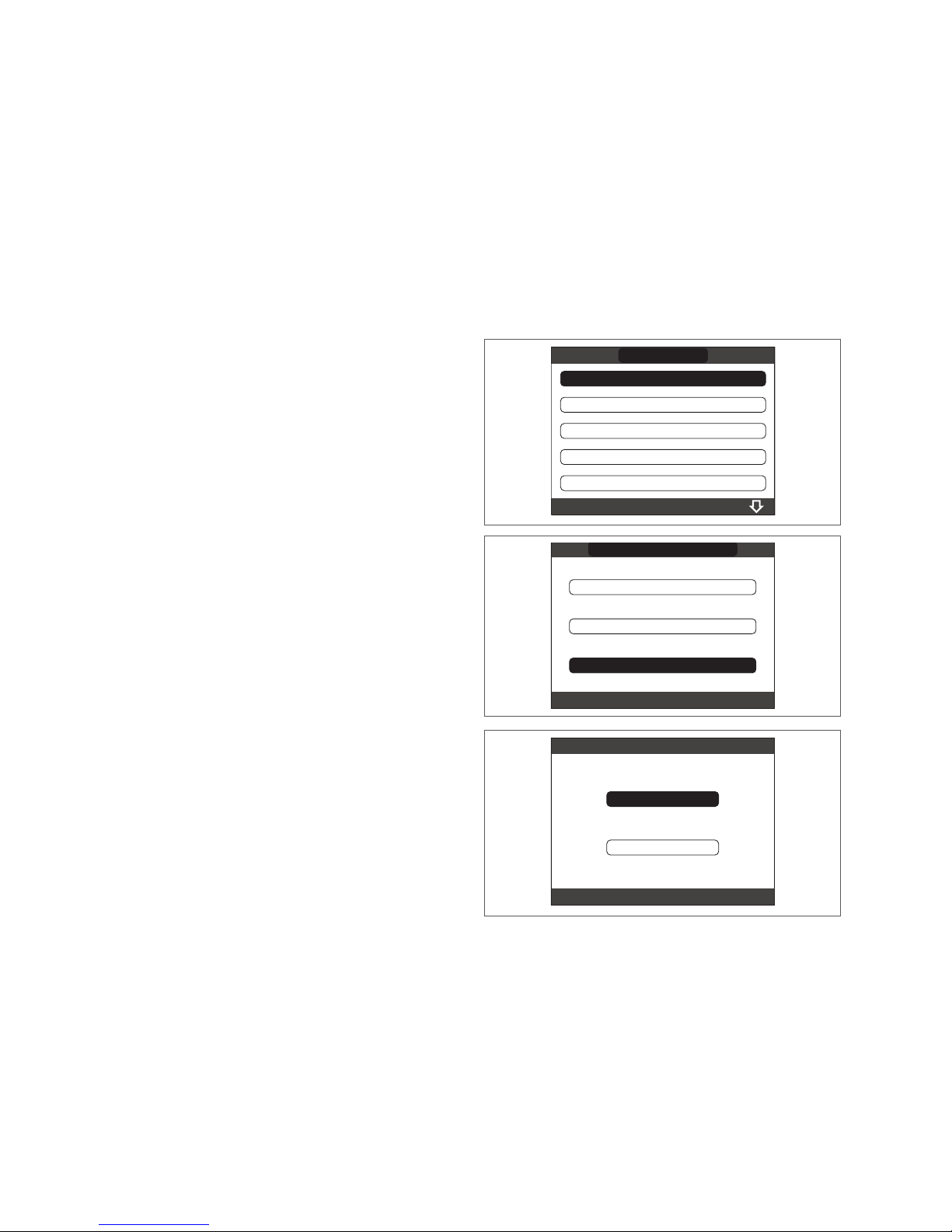
58
8.5 ELECTRICAL CHECKS
Any electrical checks must be carried out by a suitably qualied
person.
8.5.1 EARTH CONTINUITY TEST
Isolate the appliance from the electrical supply, and using a
suitable multi-meter carry out a resistance test. Connect test
leads between an appliance earth point and the earth wire of
the appliance supply cable. The resistance should be less than
1 OHM. If the resistance is greater than 1 OHM check all earth
wires and connectors for continuity and integrity.
8.5.2 SHORT CIRCUIT CHECK
Isolate the appliance from the electrical supply, and using a
suitable multi-meter, carry out a short circuit test between the
Live & Neutral connections at the appliance terminal strip.
Repeat above test on the Live & Earth connections at the
appliance terminal strip.
NOTE
Should it be found that the fuse has failed but no fault is
indicated, a detailed continuity check will be required to trace
the fault. A visual inspection of components may also assist in
locating the fault.
8.5.3 POLARITY CHECK
With the appliance connected to the electrical supply and using
a suitable multimeter, carry out the following voltage tests:
• connect test leads between the Live & Neutral connections
at the appliance terminal strip. The meter should read
approximately 230V ac. If so proceed to next stage. If not,
see 8.6.
• connect test leads between the Live & Earth connections at the
appliance terminal strip. The meter should read approximately
230V ac. If so proceed to next stage. If not, see 8.6.
• connect test leads between the Neutral & Earth connections
at the appliance terminal strip. The meter should read
approximately 0 – 15Vac. If so polarity is correct. If not, see
8.6.
8.5.4 REVERSED POLARITY OR SUPPLY FAULT
Repeat the above tests at the appliance isolator, if testing
reveals correct polarity and/or supply at the isolator, re-check
wiring and connections between the isolator and the appliance.
If tests on the isolator also reveal reversed polarity or a supply
fault, consult the local electricity supplier for advice.
DISTANCE TO EARTH CHECK
Isolate the appliance from the electrical supply, and using a
suitable multi-meter carry out a resistance test. Connect test
leads between the Live & Earth connections at the appliance
terminal strip. If the meter reads other than innity there is a
fault that must be isolated, carry out a detailed continuity check
to identify the location of the fault.
These series of checks must be carried out before attempting
any faultnding procedures on the appliance. On completion
of any task that required the disconnection and re-connection
of any electrical wiring or component, these checks must be
repeated.
8.6 FAULT FINDING
Before attempting any faultnding, the electrical checks as
detailed in 8.5 must be carried out. Isolate the appliance from
the electrical supply.
Disconnect any external controls from terminal plug, and insert
a link-wire between the two wires at the ‘TA’ connections of the
D-sub interface.
NOTE
Restore the electrical supply to the boiler and RESET
functionning. The boiler should now function as described
in section 8.2. Should the boiler fail to respond, the internal
fuses and connectors should be checked to ensure integrity
and continuity.
8.7 APPLIANCE STATUS AND FAULT CODES
When the boiler detects a temporary fault condition, the
appropriate code is shown. If/when the fault is nal, the pump
will perform 30 to 60-second post circulation (depending on the
error code) and fault code will be displayed. For combustion
fault, FAN can also post vent up to 5min if required.
8.8 REC10 SYSTEM RESET
Warning! – This operation must only be carried out by
qualiedpersonnel!
If required, the system conguration can be reset back to the
factory default conguration; however care needs to be taken
in order to carry out a successful reset:
- access the technical parameter settings as outlined in
section 8
- scroll to and select the following menu string:
MENU>TECHNICAL>INSTALLATION>SYSTEM
RESET>CONFIRM
PARAMETERS
INSTALLATION
THERMOREGULATION
RANGE RATED
TECHNICAL
INSTALLER
CALIBRATION
INSTALL
SENSOR CALIBRATION
INSTALLER
ZONES MANAGER
SYSTEM RESET
CONFIRM
CANCEL
Page 59
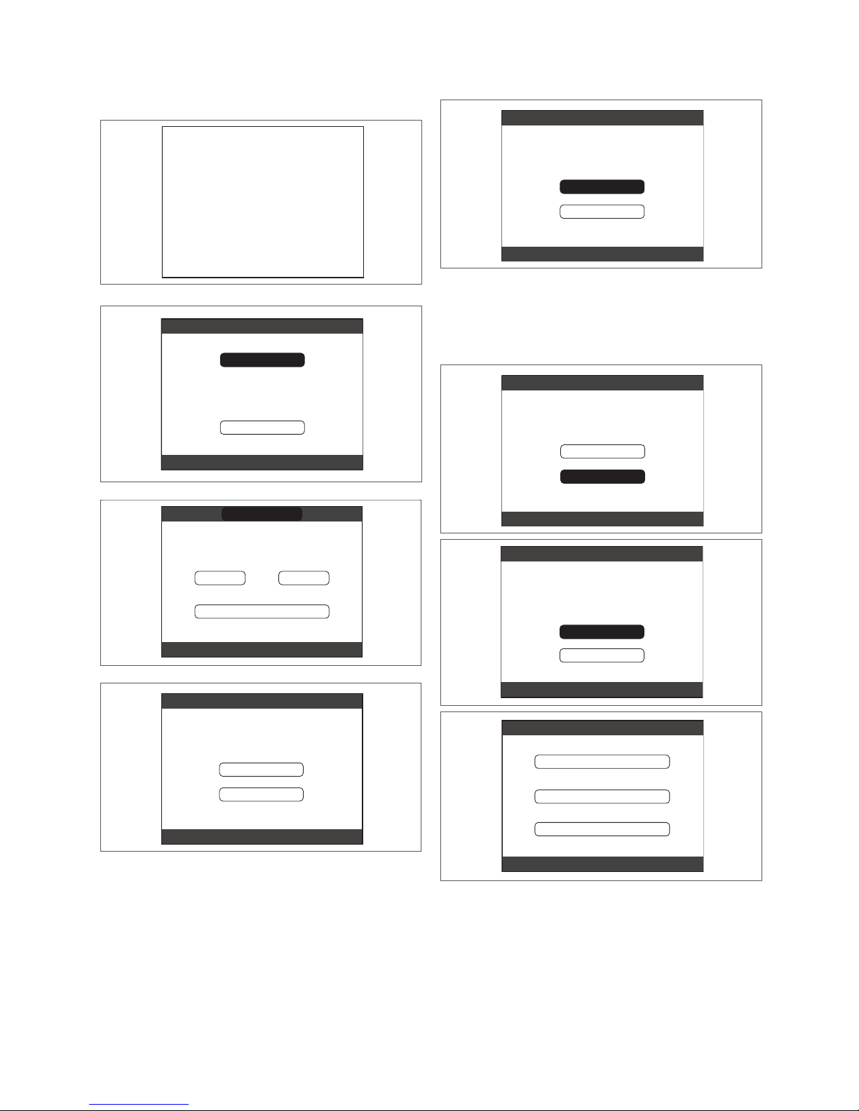
59
- the UI screen will display the rmware version – press any
key to continue
- select language (ENGLISH)
- enter the time and date
- select MASTER
- select conguration type: NEW or FROM AKM (see below)
MULTI ZONE CONTROLLER
REC10 V01.26
PRESS A BUTTON
TO CONTINUE
ITALIANO
ENGLISH
12 17:
ENTER TIME AND DATE
TIME & DATE
USE THE ARROWS TO MODIFY
18 / 11 / 2013
SELECT THE TYPE
OF CONFIGURATION
NEW
FROM AKM
FROM AKM
8.8.1 CONFIGURATION FROM AKM PCB
- Select conguration type: FROM AKM
- The REC10 will use the information/settings stored on the
AKM PCB to congure the appliance
SELECT THE TYPE
OF CONFIGURATION
NEW
FROM AKM
8.8.2 NEW CONFIGURATION
- Select conguration type: NEW
- Select location of REC10: ON BOARD
- Select PLANT type: CH ONLY – INSTANTANEOUS –
STORAGE TANK (see below)
NEW
FROM AKM
SELECT THE TYPE
OF CONFIGURATION
MACCHINA
AMBIENTE
DOVE E’ POSIZIONATO
IL MULTI ZONE CONTROLLER?
CALDAIA
PLANT
CH ONLY
INSTANTANEOUS
SELECT THE PLANT
CONFIGURATION
STORAGE TANK
- select CH ONLY if the appliance is a ‘heat’ only system
boiler
- select INSTANTANEOUS if the appliance is a combination
boiler
- then select FLUX METER (only selectable with
INSTANTANEOUS).
NOTE
After a system reset where the conguration selection is
‘new’, carry out a check on the various (applicable) installation
parameters to ensure that the ‘new’ conguration meets the
requirements of the system.
Page 60
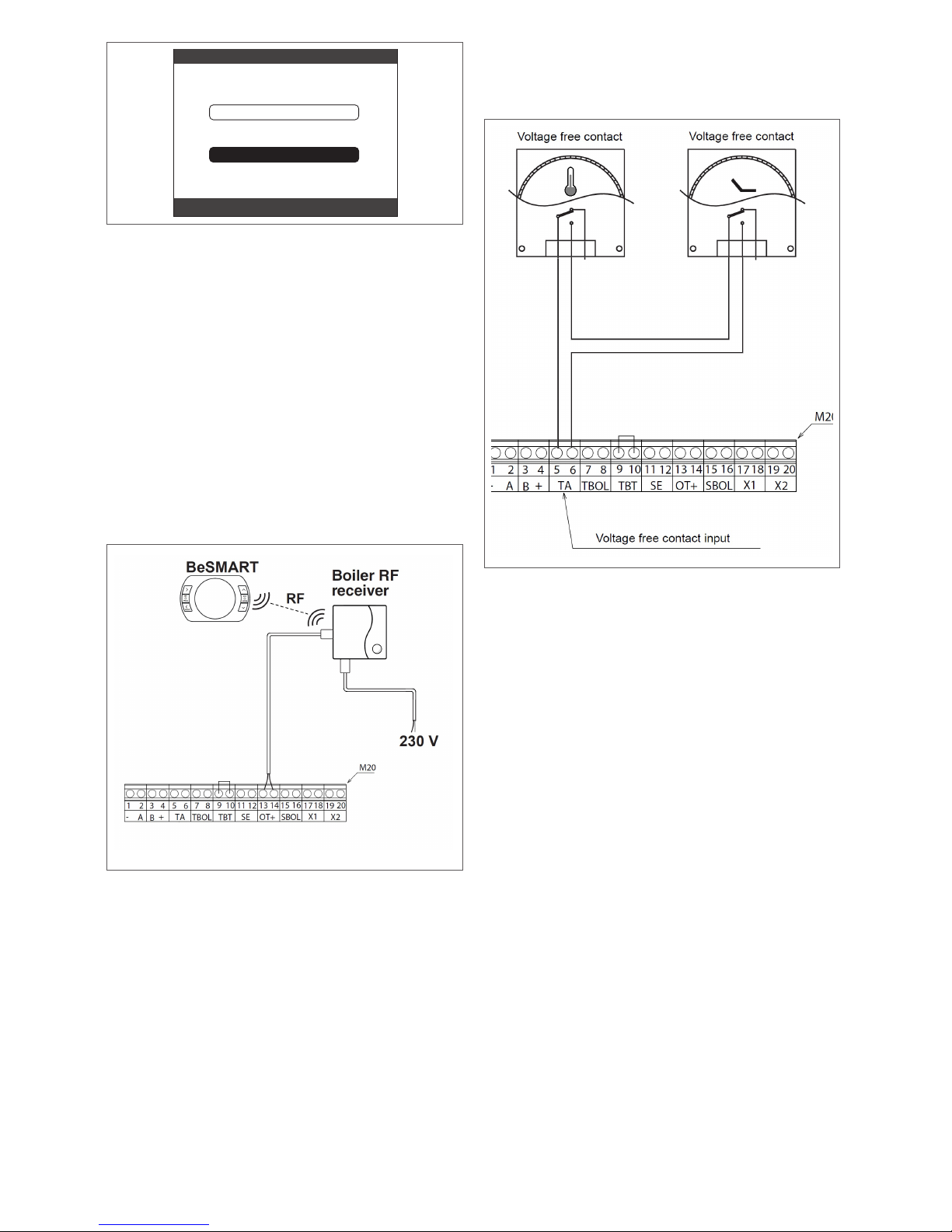
60
PLANT
FLUX METER
FLUX SWITCH
PLANT
8.9 ACCESS TO INSTALLATION PARAMETERS
Warning! – Unqualied personnel and/or ‘end-users’
should not attempt to access or adjust ANY installation
parameter; serious damage or appliance malfunction
may occur as the result of an incorrectly set parameter.
To access the installation parameters:
1. select MENU from the REC10 UI
2. simultaneously press and hold both the ‘return’ and ‘downarrow’ buttons until the display changes to show: INSERT
PASSWORD
3. using the ‘up-arrow’ button, press until ‘18’ is shown in the
display, then press ‘select’
4. use the following menu string: MENU>TECHNICAL
5. refer to the menu hierarchy tree on page 20 for further
details.
8.10 TYPICAL BESMART CONNECTION
– CONNECTED TO THE ‘D-SUB’
INTERFACE
8.11 TYPICAL CONNECTION FROM REMOTE
ROOM THERMOSTAT AND CLOCK
– CONNECTED TO THE ‘D-SUB’
INTERFACE
Page 61
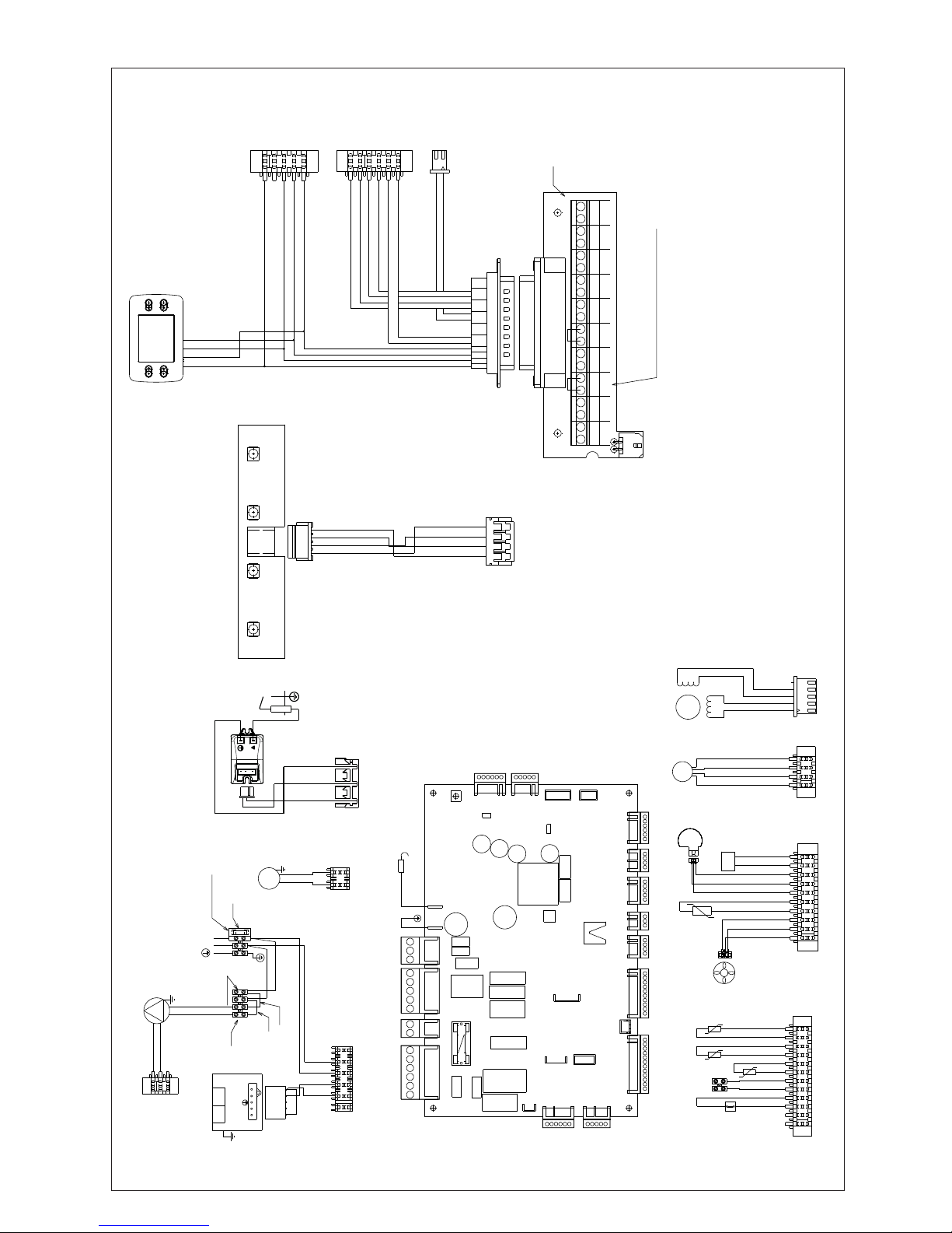
61
FUNCTIONAL DIAGRAM
AKM0x
X17
X14
1
1
X12
X23
X16
X2
X21
X8
X13
X19
X9
X25
X11
X18
X22
1
1
1
1
1
1
1
1
6
1
5
12
10
4
3
5
4
6
5
6
X15
X1
X4
X6
1
3
1
5
1
2
1
6
X3
X7
orange
F.S.
F2=4A T
CN1
X10
A9
SW1
1
2
3
4
5
6
7
8
9
10
11
12
13
14
15
16
17
18
19
20
-
A
B
+
TA
TBOL
TBT
SE
OT+
SBOL
X1
X2
9
10
7
8
5
6
1
2
14
15
16
17
black (TA)
black (TA)
pink (OT+)
pink (OT+)
orange (SE)
orange (SE)
6
1
1
2
5
1
red (+)
yellow (B)
orange (A)
black (-)
yellow (B)
black (-)
red (+)
orange (A)
white (TBT)
white (TBT)
(OT+)
(SE)
(TBT)
(TA)
+
A
B
REC
X11
X14
X25
M20
Voltage free contact input
6
1
X1
brown
blue
2
1
3
5
4
pink
blue
P
N
L
F= 3.15A F
230 V
M3
F
blue
brown
brown
brown (+)
blue (-)
PWM
brown
blue
brown
blue
brown
blue
GAS VALVE
1 2 43
OPEOPE
1
3
X8
M4
230 V
auxiliary
brown
X15
blue
F Hv
1
2
red (+)
blue (HS)
pink (PWM)
grey (-)
X13
F Lv
1
4
white
white
F.T.
-t°
-t°
R.S.
red
red
-t°
F.S.
grey
grey
yellow
F.O.H.T.
blue
blue
1
12
yellow
X9
Not use
grey
grey
1
10
orange (-)
blue (sign.)
violet (alim.)
red
red
black (alim.)
blue (sign.)
brown (-)
F.M.
1
3
D.H.W.T.
MOD
P.T.
1
3
X19
4
3
2
1
5
red
blue
violet
white
X12
3W
1
4
2
3
1
4
2
3
green (A1)
red (A2)
red (A2)
green (A1)
orange (K2)
orange (K2)
white (K1)
white (K1)
X10
J1
BE20
TSC2
blue
SE
brown
yellow/green
N
F
X6
3
1
2
Page 62
62
Key
AKM0X Main PCB
REC Remote control
BE20 Led board:
green led (working status or temporary stop)
red led (boiler lock out)
X1-X25-CN1 Connectors
S.W. CO2 function button
F.S. Flame sensor
F External fuse 3.15A F
F2 Fuse 4A T
M3-M4 Terminal strip for electrical connection high
power
M20 Terminal box
(- A B +) ● Bus 485
TA ● Room Thermosat (contact must be free
of voltage)
TBOL ● Unused
TBT ● Low temperature limit thermostat
SE ● External sensor
OT+ ● Open therm
SBOL ● Unused
X1 – X2 ● Unused
P Pump
PWM PWM signal
OPE Gas valve solenoids
F Hv Fan power supply 230 V
TSC2 Ignition transformer
S.E. Spark electrode
F.O.H.T Flow over heat thermostat
FS Flue sensor
FT Flow thermistor (NTC)
RS Return thermistor (NTC)
F.M. Flow meter
D.H.W.T Domestic hot water temperature
P.T. Pressure transducer
MOD Modulator
F Lv Fan signal control
3W 3 way valve stepper motor
9.1 RELATED DOCUMENTS
9.2 TECHNICAL DATA
SECTION 9 - LPG INSTRUCTIONS
BS 6798 INSTALLATION OF BOILERS OF RATED INPUT NOT EXCEEDING 60 kW
BS 5449 PART 1 FORCED CIRCULATION HOT WATER SYSTEMS
BS 5446 INSTALLATION OF GAS HOT WATER SUPPLIES FOR DOMESTIC PURPOSES
BS 5440 PART 1 FLUES
BS 5482 PART 1 DOMESTIC BUTANE & PROPANE GAS BURNERS IN PERMANENT DWELLINGS
Gas Pressures
evolve 24C evolve 28C evolve 32C evolve 36C
Inlet pressure 37.0 mbar 37.0 mbar 37.0 mbar 37.0 mbar
Maximum gas rate (CH) 1.40 (kg/h) 1.86 (kg/h) 2.33 (kg/h) 2.48 (kg/h)
Maximum gas rate (DHW) 2.02 (kg/h) 2.33 (kg/h) 2.69 (kg/h) 2.80 (kg/h)
Minimum gas rate (CH) 0.40 (kg/h) 0.47 (kg/h) 0.54 (kg/h) 0.56 (kg/h)
Minimum gas rate (DHW) 0.40 (kg/h) 0.47 (kg/h) 0.54 (kg/h) 0.56 (kg/h)
Injector size (mm) 1 x Ø 4.3 mm 1 x Ø 4.3 mm 1 x Ø 5.2 mm 1 x Ø 6.0 mm
Number of fan rotations with slow ignition 5,500 (rpm) 5,500 (rpm) 5,000 (rpm) 5,000 (rpm)
Maximum number of heating fan rotations 5,600 (rpm) 6,500 (rpm) 6,500 (rpm) 7,100 (rpm)
Maximum number of DHW fan rotations 7,900 (rpm) 7,900 (rpm) 7,500 (rpm) 8,100 (rpm)
Minimum number of heating fan rotations 2,000 (rpm) 2,000 (rpm) 1,900 (rpm) 2,000 (rpm)
Minimum number of DHW fan rotations 2,000 (rpm) 2,000 (rpm) 1,900 (rpm) 2,000 (rpm)
Emissions
NOx (max-min) 60 - 35 p.p.m. 40 - 40 p.p.m. 30 - 40 p.p.m. 40 - 50 p.p.m.
CO (max-min) 150 - 15 p.p.m. 200 - 30 p.p.m. 220 - 40 p.p.m. 200 - 20 p.p.m.
CO2 (max-min) 10.2 - 10.2 % 10.3 - 10.0 % 10.0 - 10.0 % 10.1 - 10.1 %
(*) CO2 tolerance= +0.6% -1%
9.3 APPLIANCE RE-CONFIGURATION FOR LPG
WARNING!
The gas supply to the appliance must remain turned OFF
until the following procedure has been completed.
1. Using the REC10 UI, navigate to STATE>BOILER and
select ‘OFF’.
2. Refer to Section 8 on how to access the ‘Service’
parameters, and use passkey ‘53’ to navigate to
MENU>SETTINGS>TECHNICAL>COMBUSTION-
MONITORING>GAS-TYPE
3. Scroll to ‘LPG’ and press the select button.
4. Use the ‘back’ button to return to the ‘TECHNICAL’ menu
and select ‘CALIBRATION’.
5. Using the data in table 9.2, adjust the fan speed settings to
the values indicated in 9.2 – pressing the select button to
conrm each change.
6. Press and hold the ‘back’ button for 2-seconds to exit the
‘Service’ parameters menu.
7. Carry out a combustion check – as detailed in Section 6.12
– using the LPG values as indicated in table 9.2 above.
NOTE
The appliance gas valve is factory set and therefore nonadjustable. Do not attempt to adjust or interfere with the
settings of the gas valve, as to do so, will cause the appliance
to malfunction and may lead to serious damage.
Page 63
63
VENT CYCLE
PARAMETERS
EXHAUST PROBE RESET
ALARM HISTORY
COMBUSTION MONITORING
SERVICE
TECHNICAL
- select GAS TYPE
COMBUSTION MONITORING
COMBUSTION OFFSET
BOILER TYPE
GAS TYPE
SERVICE
- select LPG
GAS TYPE
LPG
NG
SERVICE
The boiler DOES NOT require additional adjustments.
b
The boiler may only be converted by qualied staff.
b
After conversion apply the new rating plate
contained in the kit.
Page 64
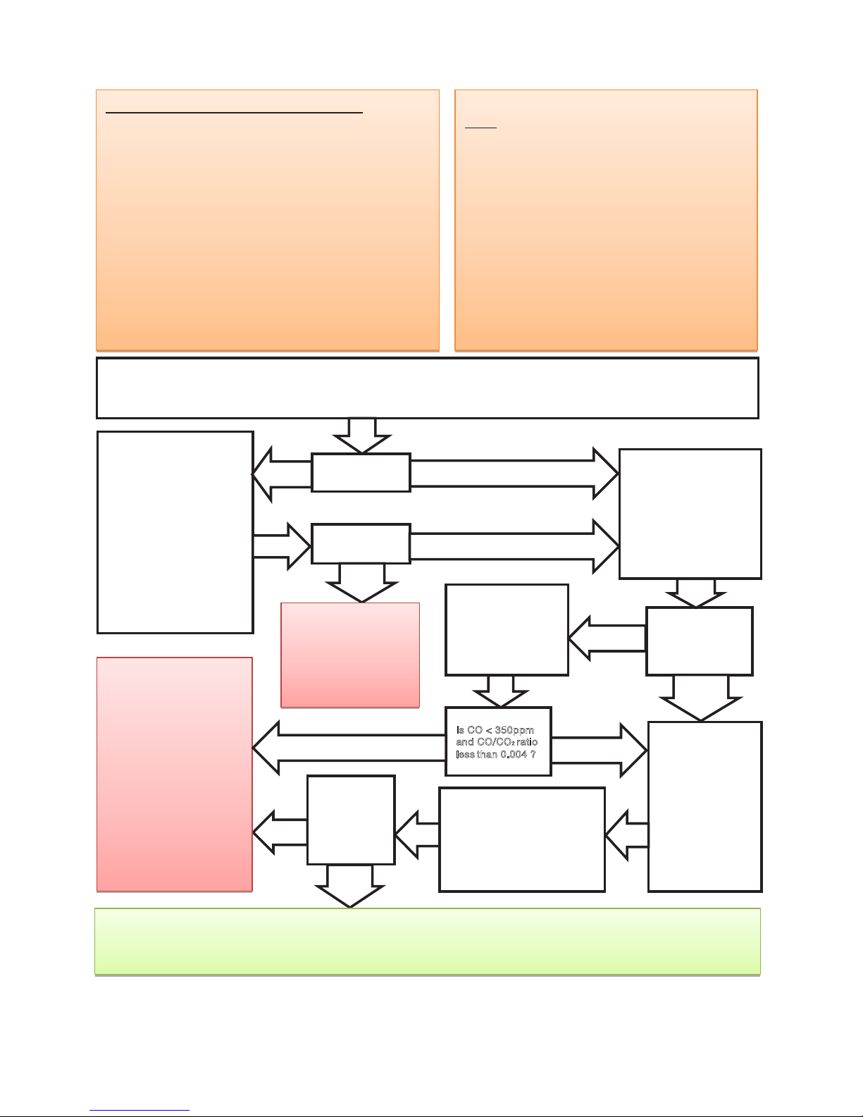
64
COMMISSIONING: CO AND COMBUSTION RATIO CHECK
SET BOILER TO MAXIMUM RATE
In accordance with, section 7.3, set boiler to operate at maximum rate (full load condition). Allow sufficient time for combustion to
stabilise. , insert analyser probe into air inlet sampling point.
Is O2 ≥20.6%
and CO2 < 0.2%?
Verify flue integrity
Analyser readings indicate
that combustion products
and inlet air are mixing.
Further investigation of the
flue is therefore required.
Check that flue components
are correctly assembled,
fixed and supported as per
boiler/flue instructions.
Check that flue and flue
terminal are not obstructed.
Is O2 ≥20.6%
and CO2 < 0.2%?
CHECK CO AND
COMBUSTION RATIO
AT MAXI MUM RA TE
With boiler still set at
maximum rate, insert
analyser probe into flue
gas sampling point.
Allow readings to
stabilise before
Is CO less than
350ppm AND
CO/CO
2 ratio less
than 0.004?
YES
NO
YES
NO
Check all seals
around the appliance
burner, internal flue
seals, door and case
seals. Rectify where
necessary.
Is CO less
than 350ppm
AND
CO/CO
2 ratio
less than
0.004?
CHECK CO AND COMBUSTION
RATIO AT MINIMUM RATE
With boiler set at minimum rate,
insert analyser probe into flue
gas sampling point. Allow
readings to stabilise before
recording.
NO
Turn off appliance and
call Vokera’s technical
helpline for advice.
The appliance must not
be commissioned until
problems are identified
and resolved.
Turn off appliance and call
Vokera’s technical helpline
for advice.
The appliance must not be
commissioned until
problems are identified and
resolved. If commissioning
cannot be fully completed,
the appliance must be
disconnected from the gas
supply in accordance with
the GSIUR.
NOTE: Check and record CO and
combustion ratio at both
maximum AND minimum rate
before contacting the Vokera
SET BOILER TO
MINIMUM RATE
In accordance with
section 7.3, set
boiler to operate at
minimum rate (to
minimum load
condition). Allow
sufficient time for
combustion to
stabilise.
YES
Is CO < 350ppm
a
nd CO/CO2 ratio
l
ess than 0.004 ?
NO
Boiler is operating satisfactorily
No further actions required.
Ensure test points are capped, boiler case is correctly replaced and all other commissioning procedures are completed.
Complete Benchmark Checklist, recording CO and combustion ratio readings as required.
NOTE
The air/gas ratio valve is factory-set and must not be
adjusted during commissioning unless this action is
recommended, following contact with the Vokera
technical help line. If any such adjustment is
recommended and further checking of the boiler is
required, the engineer must be competent to carry out
this work and to use the flue gas analyser accordingly.
If the boiler requires conversion to operate with a
different gas family (e.g., conversion from natural gas
to LPG) separate guidance will be provided by the
Vokera technical help line and must be followed.
NO
BEFORE CO AND COMBUSTION RATIO CHECK
The installation instructions should have been followed, gas
type verified and gas supply pressure/rate checked as required
prior to commissioning.
As part of the installation process, ESPECIALLY WHERE A
FLUE HAS BEEN FITTED BY PERSONS OTHER THAN THE
BOILER INSTALLER, visually check the integrity of the whole
flue system to confirm that all components are correctly
assembled, fixed and supported. Check that the maximum flue
lengths have not been exceeded and all guidance has been
followed (e.g. Technical Bulletin 008).
The flue gas analyser should be of the correct type, as specified
by BS 7967.
Before use, the flue gas analyser should have been maintained
and calibrated as specified by the manufacturer. The installer
must have the relevant competence for use of the analyser.
Check and zero the analyser IN FRESH AIR, as per analyser
manufacturer’s instructions.
YES
YES
Page 65

65
© Heating and Hotwater Industry Council (HHIC)
www.centralheating.co.uk
Benchmark Commissioning and
Servicing Section
It is a requirement that the boiler is installed and commissioned to the
manufacturers instructions and the data elds on the commissioning checklist
completed in full.
To instigate the boiler guarantee the boiler needs to be registered with the
manufacturer within one month of the installation.
To maintain the boiler guarantee it is essential that the boiler is serviced annually
by a Gas Safe registered engineer who has been trained on the boiler installed.
The service details should be recorded on the Benchmark Service Interval
Record and left with the householder.
Page 66
66
*AllinstallationsinEnglandandWalesmustbenotiedtoLocalAuthorityBuildingControl(LABC)eitherdirectlyorthrougha
CompetentPersonsScheme.ABuildingRegulationsComplianceCerticatewillthenbeissuedtothecustomer.
www.centralheating.co.uk
©HeatingandHotwaterIndustryCouncil(HHIC)
This Commissioning Checklist is to be completed in full by the competent person who commissioned the boiler as a means of demonstrating
compliance with the appropriate Building Regulations and then handed to the customer to keep for future reference.
Failuretoinstallandcommissionaccordingtothemanufacturer’sinstructionsandcompletethisBenchmarkCommissioningChecklistwillinvalidatethe
warranty.Thisdoesnotaffectthecustomer’sstatutoryrights.
GAS BOILER SYSTEM COMMISSIONING CHECKLIST
Customername: Telephonenumber:
Address:
Boilermakeandmodel:
Boilerserialnumber:
Commissionedby(PRINTNAME): GasSaferegisternumber:
Companyname: Telephonenumber:
Companyaddress:
Commissioningdate:
To be completed by the customer on receipt of a Building Regulations Compliance Certicate*
BuildingRegulationsNoticationNumber(ifapplicable):
CONTROLS(ticktheappropriateboxes)
Timeandtemperaturecontroltoheating
Roomthermostatandprogrammer/timer Programmableroomthermostat
Load/weathercompensation Optimum start control
Timeandtemperaturecontroltohotwater Cylinderthermostatandprogrammer/timer CombinationBoiler
Heatingzonevalves Fitted Notrequired
Hotwaterzonevalves Fitted Notrequired
Thermostaticradiatorvalves Fitted Notrequired
Automaticbypasstosystem Fitted Notrequired
Boilerinterlock Provided
ALL SYSTEMS
ThesystemhasbeenushedandcleanedinaccordancewithBS7593andboilermanufacturer’sinstructions Yes
Whatsystemcleanerwasused?
Whatinhibitorwasused? Quantitylitres
Hasaprimarywatersystemlterbeeninstalled? Yes No
CENTRAL HEATING MODE measureandrecord:
Gasrate m³/hr OR ft³/hr
Burneroperatingpressure(ifapplicable) mbar ORGasinletpressure mbar
Centralheatingowtemperature °C
Centralheatingreturntemperature °C
COMBINATION BOILERS ONLY
Istheinstallationinahardwaterarea(above200ppm)? Yes No
Ifyes,andifrequiredbythemanufacturer,hasawaterscalereducerbeentted? Yes No
Whattypeofscalereducerhasbeentted?
DOMESTIC HOT WATER MODEMeasureandRecord:
Gasrate m³/hr OR ft³/hr
Burneroperatingpressure(atmaximumrate) mbar ORGasinletpressureatmaximumrate mbar
Coldwaterinlettemperature °C
Hotwaterhasbeencheckedatalloutlets Yes Temperature °C
Waterowrate I/min
CONDENSING BOILERS ONLY
Thecondensatedrainhasbeeninstalledinaccordancewiththemanufacturer’sinstructionsand/orBS5546/BS6798 Yes
ALL INSTALLATIONS
Recordthefollowing:
Atmax.rate:COppm AND CO/CO
²
Ratio
Atmin.rate:(wherepossible)COppm AND CO/CO
²
Ratio
TheheatingandhotwatersystemcomplieswiththeappropriateBuildingRegulations Ye s
Theboilerandassociatedproductshavebeeninstalledandcommissionedinaccordancewiththemanufacturer’sinstructions Ye s
Theoperationoftheboilerandsystemcontrolshavebeendemonstratedtoandunderstoodbythecustomer Yes
Themanufacturer’sliterature,includingBenchmarkChecklistandServiceRecord,hasbeenexplainedandleftwiththecustomer Yes
CommissioningEngineer’sSignature
Customer’sSignature
(Toconrmsatisfactorydemonstrationandreceiptofmanufacturer’sliterature)
www.centralheating.co.uk
Page 67
67
*AllinstallationsinEnglandandWalesmustbenotiedtoLocalAuthorityBuildingControl(LABC)eitherdirectlyorthrougha
CompetentPersonsScheme.ABuildingRegulationsComplianceCerticatewillthenbeissuedtothecustomer.
©HeatingandHotwaterIndustryCouncil(HHIC) www.centralheating.co.uk
It is recommended that your heating system is serviced regularly and that the appropriate Service Interval Record is completed.
Service Provider
BeforecompletingtheappropriateServiceRecordbelow,pleaseensureyouhavecarriedouttheserviceasdescribedinthemanufacturer’sinstructions.
Alwaysusethemanufacturer’sspeciedsparepartwhenreplacingcontrols.
SERVICE RECORD
SERVICE 01
Date:
Engineername:
Companyname:
TelephoneNo:
GassaferegisterNo:
Record:
Atmax.rate: COppm AND CO² %
Atmin.rate:
(WherePossible) COppm AND CO
²
%
Comments:
Signature
SERVICE 02
Date:
Engineername:
Companyname:
TelephoneNo:
GassaferegisterNo:
Record:
Atmax.rate: COppm AND CO² %
Atmin.rate:
(WherePossible) COppm AND CO
²
%
Comments:
Signature
SERVICE 03
Date:
Engineername:
Companyname:
TelephoneNo:
GassaferegisterNo:
Record:
Atmax.rate: COppm AND CO² %
Atmin.rate:
(WherePossible) COppm AND CO
²
%
Comments:
Signature
SERVICE 04
Date:
Engineername:
Companyname:
TelephoneNo:
GassaferegisterNo:
Record:
Atmax.rate: COppm AND CO² %
Atmin.rate:
(WherePossible) COppm AND CO
²
%
Comments:
Signature
SERVICE 05
Date:
Engineername:
Companyname:
TelephoneNo:
GassaferegisterNo:
Record:
Atmax.rate: COppm AND CO² %
Atmin.rate:
(WherePossible) COppm AND CO
²
%
Comments:
Signature
SERVICE 06
Date:
Engineername:
Companyname:
TelephoneNo:
GassaferegisterNo:
Record:
Atmax.rate: COppm AND CO² %
Atmin.rate:
(WherePossible) COppm AND CO
²
%
Comments:
Signature
SERVICE 07
Date:
Engineername:
Companyname:
TelephoneNo:
GassaferegisterNo:
Record:
Atmax.rate: COppm AND CO² %
Atmin.rate:
(WherePossible) COppm AND CO
²
%
Comments:
Signature
SERVICE 08
Date:
Engineername:
Companyname:
TelephoneNo:
GassaferegisterNo:
Record:
Atmax.rate: COppm AND CO² %
Atmin.rate:
(WherePossible) COppm AND CO
²
%
Comments:
Signature
SERVICE 09
Date:
Engineername:
Companyname:
TelephoneNo:
GassaferegisterNo:
Record:
Atmax.rate: COppm AND CO² %
Atmin.rate:
(WherePossible) COppm AND CO
²
%
Comments:
Signature
SERVICE 10
Date:
Engineername:
Companyname:
TelephoneNo:
GassaferegisterNo:
Record:
Atmax.rate: COppm AND CO² %
Atmin.rate:
(WherePossible) COppm AND CO
²
%
Comments:
Signature
Page 68

Cod. 20131172 - 09/17 - Ed. 4
Registered address:
Vokèra Ltd
Borderlake House
Unit 7 Riverside Industrial Estate
London Colney
Herts AL2 1HG
www.vokera.co.uk
www.vokera.ie
Sales, General Enquires
T 0844 391 0999
F 0844 391 0998
Vokèra Ireland
West Court, Callan
Co Kilkenny
T 056 7755057
F 056 7755060
Vokèra Limited reserve the right to change
specication without prior notice
Consumers statutory rights are not affected.
Company Reg No: 1047779
RANGE RATED - EN 483
The max CH input of this boiler has been adjusted to_____ kW,
equivalent to _____ rpm max CH fan speed.
Date___/____/____
Signature _____________________
Boiler serial number
_____________________
 Loading...