

Evolv DNA 200
Specifications
Minimum
Typical
Max
Output Power
1 Watt
200 Watts
Output Voltage
1 Volt
9.0 Volts
Output Current, continuous
50.0 Amps
Output Current, instantaneous peak
55.0 Amps
Atomizer Resistance, temperature sensing wire, cold
.08 Ohm
.4 Ohm
1.0 Ohm
Atomizer Resistance, kanthal wire
.08 Ohm
.7 Ohm
2.0 Ohms
Temperature Limit
200°F
450°F
600°F
Input Voltage
9.0 Volts
11.1 Volts
12.6 Volts
Input Current
.5 Amps
9.0 Amps
23.0 Amps
Screen On Current
18mA
Quiescent Current
4.5 mA
Power Down Current
5uA
Efficiency
97%
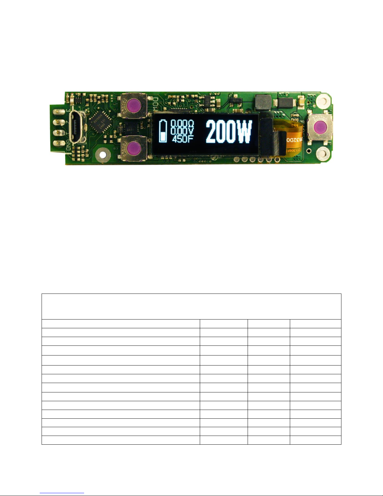
200 Watt Variable Power Module with Temperature Protection and USB
Preliminary Datasheet
The DNA 200 is a power regulated digital switch-mode DC-DC converter for personal vaporizers.
It features Evolv’s patented Wattage Control, Temperature Protection, Preheat, Digital User Controls,
OLED Screen, Onboard Buttons and Synchronous Rectification for maximum battery life and minimal
heat generation. The DNA 200 runs from a 3 cell lithium polymer battery, and features cell-by-cell
battery monitoring and integrated balance charger. The USB port and Evolv’s EScribe software can be
used to customize or monitor the user experience. It is the most advanced personal vaporizer controller
ever made.

Weight
15g Footprint
.71” x 2.80”
18mm x 71mm
Thickness
.32”
Screen size
.91” OLED
Contents
Specifications ................................................................................................................................................ 1
Temperature Protection ............................................................................................................................... 3
Preheat ...................................................................................................................................................... 3
Attaching a New Atomizer ........................................................................................................................ 4
Operation ...................................................................................................................................................... 5
Display ....................................................................................................................................................... 5
Temperature Protected ......................................................................... Error! Bookmark not defined.
Non-temperature Protected .................................................................. Error! Bookmark not defined.
Modes ....................................................................................................................................................... 6
Error Messages ......................................................................................................................................... 7
Auto power down ..................................................................................................................................... 7
Pinout .......................................................................................................................................................... 12
Wiring .......................................................................................................................................................... 13
Recommended wire sizes ....................................................................................................................... 13
External component recommendations ................................................................................................. 13
Mounting..................................................................................................................................................... 14
Mechanical Dimensions .............................................................................................................................. 15

Temperature Protection
The DNA 200 directly measures and limits the temperature of the heating coil during operation.
By preventing the coil from becoming too hot regardless of fluid, wicking or airflow, a variety of
undesirable situations can be prevented. For example, appropriate temperature settings will prevent the
wicking material from charring, which compromises taste and introduces unintended chemicals into the
vapor. Appropriate temperature settings will also reduce the breakdown of flavoring and base liquid
components, which could impact taste or safety.
Evolv’s Temperature Protection Technology requires a heating coil made from Nickel 200 alloy,
rather than Nickel Chromium or Kanthal alloys. Nickel 200 is commercially pure nickel. It is often sold in
vapor shops and online as “non-resistance wire.” If the temperature reaches the maximum value, the
wattage applied to the atomizer coil is reduced to prevent overheating. Please note that the
temperature reading is the average temperature of the atomizer coil, and care should be taken to
construct the heating coil so that the temperature is uniform, without hot or cold spots.
Because wattage, not temperature controls vapor volume, large vapor volumes can be produced
without unnecessarily high temperatures. Temperature Protection is most helpful if the atomizer begins
to dry out, the user pauses during a puff, the beginning or end of the puff, or if the wattage setting is
inappropriate for the attached atomizer.
In normal operation, when the device is not firing the maximum temperature setting is
displayed on the screen. When the device is firing, the actual average temperature of the coil is
displayed on the screen.
By default, the Temperature Protection setting is 450° Fahrenheit. To change the limit
1) Lock the device by pressing the Fire button five times.
2) Hold down the UP and DOWN adjust buttons for two seconds.
3) After two seconds, the maximum temperature will be displayed, and the UP and DOWN buttons
should be released.
4) Use the UP and DOWN buttons to adjust the maximum temperature
5) When the display shows the desired maximum temperature, press the Fire button to exit
temperature adjust mode.
The maximum temperature is adjustable between 200° Fahrenheit and 600° Fahrenheit. To
disable the temperature protection entirely, adjust the limit up to 600 degrees, then press the UP
button one additional time. The temperature limit will read OFF.
To switch to Celsius temperature, adjust temperature down to 200° Fahrenheit, then press the
DOWN one button one additional time. The temperature will switch to reading and adjusting in Celsius.
Preheat
When the DNA 200 is used with a temperature sensing atomizer, an additional feature called
Preheat is activated. No vapor is produced when the temperature is below the boiling point of the
liquid. Preheat applies extra power until the heating coil is up to operating temperature to shorten the

delay between pressing the fire button and generating vapor. Because preheat is temperature based, it
will not overheat or burn the vapor.
Attaching a New Atomizer
The DNA 200 uses the resistance of the atomizer to calculate the temperature of the heating
coil. It continually looks to see whether a new or changed atomizer has been connected. If you are using
temperature protection, be careful to only attach new atomizers that have cooled to room temperature
to the device. If a new atomizer is attached to the DNA 200 before it has cooled down, the temperature
may read and protect incorrectly until the new atomizer cools.
When you connect a new atomizer or disconnect and reconnect your existing atomizer, the DNA
200 will prompt you to confirm this change. When you fire the first time, before activating the DNA 200
will prompt “New Coil? UP YES/DOWN NO”. When you see this prompt, if you have attached a new
atomizer, press the UP button. If you have disconnected and reconnected the same atomizer, press the
DOWN button.

Operation
Basic operation of the DNA 200 is as follows. To wake the device from power off state, tap the
Fire button. To generate vapor, press the Fire button. To change the wattage setting for more or less
vapor, click or hold the Up and Down buttons.
Display
The DNA 200 has a small .91” diagonal white OLED screen. The screen is attached to the main
board by a flexible cable, allowing freedom in the design of your device. The screen’s default position is
on top of the board, between the fire and adjust buttons. This allows for easy assembly. The screen
connects to the board with a ZIF connector, so alternate placement is possible. It is also possible to
order screens with custom length and shape flexible cables, allowing screen placement anywhere in the
device. Please use caution when handling the screen and design the device so that the cable will be
secured or strain relieved in operation.
Watt setting: The power level currently set on the DNA 200.
Battery indicator: The current state of charge of the battery.
Temperature display: When not firing, the maximum heating coil temperature setting. While firing, the
actual temperature of the heating coil is displayed.
Volts display: The output voltage being supplied to the atomizer.
Ohms display: The resistance of the atomizer attached to the device. This is measured only when the
unit is supplying power to the atomizer. At other times, it shows the most recent measurement.

Modes
Locked mode: Pressing the fire button five times with less than .7 seconds between presses will cause
the device to enter Locked mode. In Locked mode, the device will not fire and the output power will not
adjust accidentally. While in Locked mode, the screen will be off, except that pressing a button will show
“Locked, Click 5X”. To exit Locked mode, press the fire button 5 times.
Stealth mode: While locked, holding the fire and down buttons simultaneously for five seconds will
switch to stealth mode. In this mode the display is off. It will still show error and lock messages. To
switch back to normal display mode, hold down the fire and down buttons simultaneously for 5 seconds.
This setting is stored to internal flash memory, and remains if power is removed.
Power Locked mode: Holding down both the up and down buttons for two seconds will place the device
in Power Locked mode. In this mode, the mod will operate normally, but you will not be able to change
the power setting. This mode prevents accidental power level changes due to the buttons being pressed
while in a pocket. To exit Power Locked mode, hold the up and down buttons for two seconds.
Resistance lock: The DNA 200 relies on the cold resistance of the atomizer to measure temperature
accurately. If the connection is not stable or if you find the measured resistance drifts with time, it may
be desirable to lock the atomizer resistance. To do so, while locked hold both the Fire and Up buttons
for two seconds to enter Resistance Lock mode. In this mode, the DNA 200 will use the present atomizer
cold resistance without refinement until the atomizer is disconnected or the resistance lock is disabled.
A lock symbol will replace the ohm symbol on the display. To disable resistance lock, repeat the
procedure to lock it.
Max Temperature Adjust: From Locked Mode, holding down both the up and down buttons for two
seconds will place the device in Max Temperature Adjust mode. Once this mode is entered, the max
temperature will be displayed. The up and down buttons are used to adjust the max temperature. To
save the new temperature setting and exit, press the Fire button.

Error Messages
The DNA 200 will indicate a variety of error states.
Check Atomizer: The DNA does not detect an atomizer, the atomizer has shorted out, or the atomizer
resistance is incorrect for the power setting.
Shorted: The atomizer or wiring are short circuited.
Weak Battery: The battery needs to be charged, or a higher rate battery needs to be used. If this
happens, the DNA 200 will continue to fire the atomizer, but will not be able to provide the desired
wattage. The Weak Battery message will continue to flash for a few seconds after the end of puff.
Temperature Protected: The heating coil reached the maximum allowed temperature during the puff. If
this happens, the DNA 200 will continue to fire, but will not be able to provide the desired wattage.
Ohms Too High: The resistance of the atomizer coil is too high for the current wattage setting. If this
happens, the DNA 200 will continue to fire, but will not be able to provide the desired wattage. The
Ohms Too High message will continue to flash for a few seconds after the end of puff.
Ohms Too Low: The resistance of the atomizer coil is too low for the current wattage setting. If this
happens, the DNA200 will continue to fire, but will not be able to provide the desired wattage. The
Ohms Too Low message will continue to flash for a few seconds after the end of puff.
Too Hot: The DNA 200 has onboard temperature sensing. It will shut down and display this message if
the internal board temperature becomes excessive.
Auto power down
The screen will be at full brightness while firing. After 10 seconds with no button presses, the screen will
dim. 30 seconds after the last button press, the screen will fade out and the device will go into sleep
mode. To wake the device, press the fire button.

Charger
The DNA 200 has a built in 1A USB charger. It automatically detects the type of USB power supply it is
connected to, so it can be plugged into standard PC USB ports or higher power chargers. The max charge
current is based on the cell capacity as programmed in EScibe.
Cell-by-cell monitoring
The DNA 200 runs from a three cell battery. Because lithium polymer cells can be damaged by excessive
discharge, with multi-cell series batteries it is important to measure each cell in the battery
independently and stop firing the atomizer when any of the cells reaches the cutoff voltage. The DNA
200 uses the battery pack taps to monitor each cell.
Cell Balancer
During charging, is vital that none of the batteries charge beyond 4.2 volts per cell. If one of the cells in
the battery has more charge than the others, its voltage will be higher. During charging, the DNA 200
will turn on a “balancer” to charge that cell slower than the others.
By monitoring and charging each cell individually, the safety of a multi-cell pack is equivalent to using a
single cell. Many products, from power tools to laptops to electric vehicles, use multi-cell packs. All of
them use cell by cell monitoring and balancing to operate safely.

Escribe
Escribe is a software package used to configure and modify the operation of your DNA 200. It
installs on a Windows PC and connects to your DNA 200 using the USB port.
When you connect your DNA 200 to the PC, press the “Connect and Download Settings” button to
download the settings presently on your device to Escribe. After you make changes, press the “Upload
Settings to Device” to save the new settings to the device.
Atomizer Tab
Battery Tab
It is important to set the Capacity setting for the battery to the proper value for your battery. The DNA
200 measures the energy put into the battery while charging and drawn from the battery while firing in
order to know the battery life remaining. You can also change to battery type and cutoff.

Screen Tab
The Screen tab allows you to change the characteristics of the screen, and also to change or replace any
of the status and error messages with inages. Images must be 128 x 32 pixel monochrome bitmaps.
Research Tab
The Research tab is primarily for data logging or restricting the device for use in research.
Information Tab

The Information tab is designed to look at what the DNA 200 is doing in real time. Analyze will measure
the atomizer like a milli-ohm meter. Monitor will look at the inputs and outputs of the DNA 200 as you
use it.

Pinout (shown bottom side)
Pin Number
Pin Name
Function
Out
Out
Power output.
1
Fire +
Positive side of the fire button.
2
Fire-
Negative side of the fire button.
3
Up-
Negative side of the power up button.
4
Up+
Positive side of the power up button.
5
Down +
Positive side of the power down button.
6
Down -
Negative side of the power down button.
GND
GND
Power output. GND is the ground return for the atomizer. It is connected
internally to B-. There are three ground lugs and one ground pad.
B+
B+
Positive battery terminal.
B-
B-
Negative battery terminal. Internally connected to Gnd
Tap
Tap
Positive battery terminal. Larger terminal is the main power connection
for the battery.

Wiring
Recommended wire sizes
Minimum size
Recommended size
Maximum size
Battery, silicone insulated
20 gauge
18 gauge
16 gauge
Battery, PVC Insulated
20 gauge
16 gauge
16 gauge
Output, silicone insulated
14 gauge
12 gauge
12 gauge
Switches, if used
28 gauge
24 gauge
22 gauge
The atomizer is connected to the OUT pad. If the DNA 200 is not being grounded through the
mounting screws, the GND pad should connect to the negative side of the connector. The battery is
connected to the B+ and B- terminals. It is important to use appropriately sized wire when using the
DNA. Too small wire will not perform well, and significantly undersized wire can burn out. The output
wires should be silicone or Teflon insulated only, and at least 14 gauge. The input wire carries less
current, and can be as small as 20 gauge wire if silicone or Teflon insulated.
External component recommendations
The DNA 200 is a self-contained power regulator which does not require external components
for its user interface. However, it does support the use of external interface components if desired.
Fire button:
Use a momentary on, normally open type switch or button. A standard pushbutton switch is
appropriate. The switch is a logic function – all power switching is handled with transistors inside the
DNA module, so the switch does not need to be rated for power. A waterproof or processed sealed
switch is recommended.
Up/Down buttons:
The small onboard buttons labeled UP and DOWN allow the user to increase or decrease the
power level in .1 Watt increments. The onboard tactile switches are waterproof and rated for 300,000
actuations. Please make sure the actuator presses down on the button only, and does not rotate or drag
the top surface. Alternatively, remote normally open type switches or buttons can be attached to the UP
and DOWN mounting holes for customization.
Battery:
The DNA 200 runs from a 3s lithium polymer type battery pack. This type of battery requires
cell-by-cell battery monitoring and balance charging to operate safely. The DNA 200 connects to the cell
taps on the battery pack with a four position JST-XH connector. The tap connector must be connected
for the DNA 200 to run.

Mounting
The DNA 200 has onboard switches for adjusting the power level and activating the output. Each
of these functions also has optional through-hole pads for using remote buttons.
The DNA 200 has three mounting holes on the PCB. These holes are designed for #0 screws.
There is an extended mounting pad of .125” diameter around each. These holes are electrically
connected to each other and to ground. With careful design, the mounting pads can be used to ground
the chassis to the DNA 200, and pass the output current through chassis to the connector. However, if
using this method, ensure that the PCB remains in good contact with the board at all times. Split lock
washers and a RoHS chromate conversion coating on the chassis are recommended.

Mechanical Dimensions
Evolv has 3D models of the DNA 200 available on their website in IGES, STL and Solidworks format.
 Loading...