

Page 1

RAGE 5
Original Instructions
EN
DE
ES
FR
IT
NL
Date Published: 15 / 08 / 2013Written in UK English
Page 2

www.evolutionpowertools.com
TABLE OF CONTENTS
English Page 02
Deutsch Seite 32
Español Página 68
Français Page 104
Italiano Pagina 140
Nederlands Pagina 176
Important Information Page 03
Guarantee Page 03
Specification Page 04
Labels & Symbols Page 05
General Safety Rules Page 06
Safety Precautions for All Saws Page 06
Additional Specific Safety Rules Page 08
Machine Overview Page 10
Service Parts Diagram Page 11
Assembly Page 13
Operation Page 16
Maintenance Page 28
Environmental Protection Page 29
Trouble Shooting Guide Page 29
EC - Declaration of Conformity Page 30
2
Page 3

www.evolutionpowertools.com
EN
IMPORTANT
Please read these operating and safety
instructions carefully and completely. For
your own safety, if you are uncertain about
any aspect of using this equipment please
access the relevant Technical Helpline,
the number of which can be found on
the Evolution Power Tools website. We
operate several Helplines throughout our
worldwide organization, but Technical
help is also available from your supplier.
WEB
www.evolutionpowertools.com/register
EMAIL
info@evolutionpowertools.com
Congratulations on your purchase
of an Evolution Power Tools Machine.
Please complete your product registration
‘online’ as explained in the A4 online
guarantee registration leaflet included
with this machine. You can also scan the
QR code found on the A4 leaflet with
a Smart Phone. This will enable you to
validate your machine’s guarantee period
via Evolutions website by entering your
details and thus ensure prompt service
if ever needed. We sincerely thank you
for selecting a product from Evolution
Power Tools.
EVOLUTION LIMITED GUARANTEE
Evolution Power Tools reserves the right
to make improvements and modifications
to the product design without prior notice.
Please refer to the guarantee registration
leaflet and/or the packaging for details of
the terms and conditions of the guarantee.
Evolution Power Tools will, within the
guarantee period, and from the original date of
purchase, repair or replace any goods found to
be defective in materials or workmanship. This
guarantee is void if the tool being returned
has been used beyond the recommendations
in the Instruction Manual or if the machine
has been damaged by accident, neglect, or
improper service.
This guarantee does not apply to machines
and / or components which have been altered,
changed, or modified in any way, or subjected
to use beyond recommended capacities
and specifications. Electrical components
are subject to respective manufacturers’
warranties. All goods returned defective shall
be returned prepaid freight to Evolution Power
Tools. Evolution Power Tools reserves the right
to optionally repair or replace it with the same
or equivalent item.
There is no warranty – written or verbal – for
consumable accessories such as (following list
not exhaustive) blades, cutters, drills, chisels
or paddles etc. In no event shall Evolution
Power Tools be liable for loss or damage
resulting directly or indirectly from the use
of our merchandise or from any other cause.
Evolution Power Tools is not liable for any
costs incurred on such goods or consequential
damages. No officer, employee or agent of
Evolution Power Tools is authorized to make
oral representations of fitness or to waive any
of the foregoing terms of sale and none shall
be binding on Evolution Power Tools.
Questions relating to this limited guarantee
should be directed to the company’s head
oce, or call the appropriate Helpline number.
DE
ES
FR
IT
NL
3
Page 4

www.evolutionpowertools.com
SPECIFICATIONS
MACHINE METRIC IMPERIAL
Motor UK/EU: 230-240V ~ 50Hz (S6 40%) 1800W 8A
Motor UK:
110V
~ 50Hz 1600W 15A
Table Dimensions 656 x 1260mm 26 x 49-5/8”
Speed (No Load) 2500min
-1
2500rpm
CUTTING CAPACITIES
Mild Steel Plate – Max Thickness 6mm 1/4”
Wood - Maximum Depth Of Cut At 90
Wood - Maximum Depth Of Cut At 45
0
0
80mm 3-1/8˝
55mm 2-1/8˝
Weight 38kg 84lb
Riving Knife Thickness 1.8mm .070˝
BLADE
Diameter 255mm 10˝
Bore 25.4mm 1˝
Kerf 2mm .078˝
Teeth 28 28
Max Speed 2750min
-1
2750rpm
NOISE & VIBRATION DATA
Sound Pressure LPA 230-240V - 91.9dB(A)
110V - 90.2dB(A)
Sound Power Level LWA 230-240V - 104.5dB(A)
110V - 104.2dB(A)
Uncertainty K 3dB(A)
4
Page 5
www.evolutionpowertools.com
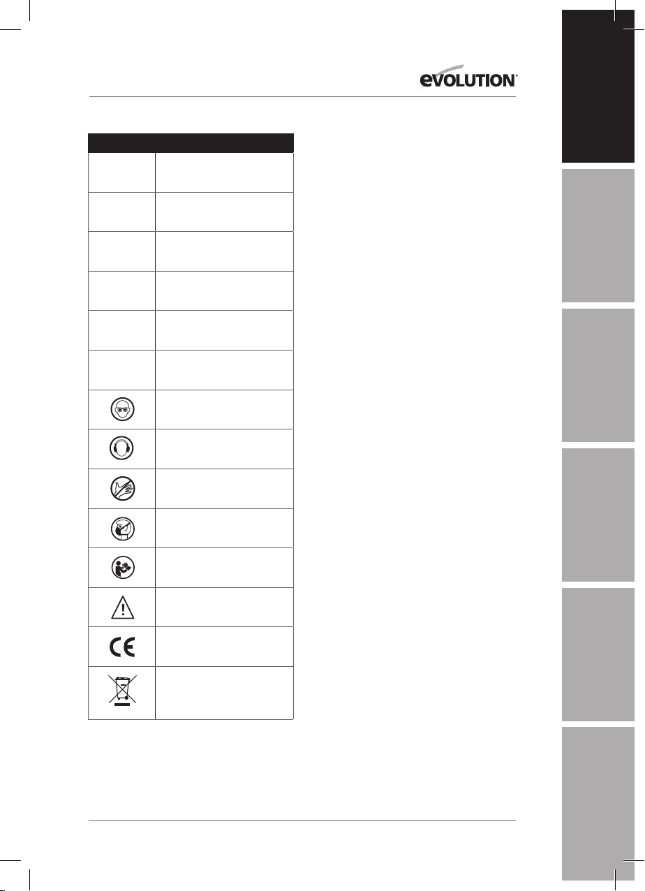
LABELS & SYMBOLS
Symbol Description
V
Volts
EN
WARNING: Do not operate the saw if any
warning and/or instruction labels are missing
or damaged. Contact evolution power tools for
replacement labels.
Hz
Min
n
A
Amperes
Hertz
Only use genuine Evolution replacement
blades. Unauthorized blades may be
dangerous! Keep the blades securely fastened.
Check for debris before installing any new
DE
blades and do not use dull or broken blades.
-1
Speed
Check the blades regularly for condition
and wear. Damaged or worn blades should
be replaced immediately. Loose fitting
~
Alternating current
or damaged guards must be replaced
immediately. Beware of ejecting chips as they
may be HOT. Always make provisions for safe
o
No load speed
handling of excess material.
ES
VIBRATION LEVEL
Wear safety goggles
Wear ear protection
Do not touch
The declared vibration total value has been
measured in accordance with a standard test
method and may be used for comparing one
tool with another.
The declared vibration total value may also be
used in a preliminary assessment of exposure.
WARNING: The vibration emission during
Wear dust protection
Read Instructions
Warning
CE certification
Waste electrical and
electronic equipment
actual use of the power tool can differ from the
declared total value depending on the ways
in which the tool is used. The need to identify
safety measures and to protect the operator
are based on an estimation of exposure in the
actual conditions of use (taking account of all
parts of the operating cycle, such as the times
the tool is switched off, when it is running idle,
in addition to trigger time).
To obtain an additional copy of your manual,
please contact Evolution Power Tools at:
UK: +44 (0)114 251 1022
USA: 1-866-EVO-TOOL
WEB: www.evolutionpowertools.com
FR
IT
NL
5
Page 6

www.evolutionpowertools.com
IMPORTANT SAFETY INSTRUCTIONS
To reduce the risk of electric shock, this
equipment is fitted with an approved cord and
plug for its intended country of use. Do not
change the cord or plug in any way.
GENERAL SAFETY RULES
Read and understand all instructions before
operating this product. Failure to follow all
instructions listed below may result in electric
shock, fire and / or serious personal injury.
SAVE THESE INSTRUCTIONS
FOR FUTURE REFERENCE.
WARNING: When using electric tools basic
safety precautions should always be followed
to reduce the risk of fire, electric shock and
personal injury including the following:
Read all these instructions before
attempting to operate this product and save
these instructions.
The term “power tool” in the warnings refers to
your mains-operated (corded) power tool or
battery-operated (cordless) power tool.
SAFETY INSTRUCTIONS FOR ALL SAWS
WARNING: Read all instructions. Failure
to follow all instructions listed below may
result in electric shock, fire and/or serious
injury.
SAVE THESE INSTRUCTIONS
1) Work area safety
a) Keep work area clean and well lit.
Cluttered and dark areas invite accidents.
b) Do not operate power tools in explosive
atmospheres, such as in the presence of
flammable liquids, gases or dust. Power
tools create sparks which may ignite the dust
or fumes.
c) Keep children and bystanders away
while operating a power tool.
Distractions can cause you to lose control.
2) Electrical safety
a) Power tool plugs must match the outlet.
Never modify the plug in any way. Do not use
any adapter plugs with earthed (grounded)
power tools.
Unmodified plugs and matching outlets will
reduce risk of electric shock.
b) Avoid body contact with earthed
or grounded surfaces such as pipes,
radiators, ranges and refrigerators. There is
an increased risk of electric shock if your body
is earthed or grounded.
c) Do not expose power tools to rain or wet
conditions. Water entering a power tool will
increase the risk of electric shock.
d) Do not abuse the cord. Never use the
cord for carrying, pulling or unplugging
the power tool. Keep cord away from heat,
oil, sharp edges or moving parts. Damaged or
entangled cords increase the risk of electric shock.
e) When operating a power tool outdoors,
use an extension cord suitable for outdoor
use. Use of a cord suitable for outdoor use
reduces the risk of electric shock.
f) If operating a power tool in a damp
location is unavoidable, use a residual
current device (RCD) protected supply.
Use of an RCD reduces the risk of electric shock.
3) Personal safety
a) Stay alert, watch what you are doing
and use common sense when operating
a power tool. Do not use a power tool
while you are tired or under the influence of
drugs, alcohol or medication. A moment of
inattention while operating power tools may
result in serious personal injury.
b) Use safety equipment. Always wear
eye protection. Safety equipment such as
6
Page 7

www.evolutionpowertools.com
EN
dust mask, non-skid safety shoes, hard hat,
or hearing protection used for appropriate
conditions will reduce personal injuries.
c) Avoid accidental starting. Ensure
the switch is in the off-position before
plugging in. Carrying power tools with your
finger on the switch or plugging in power tools
that have the switch on invites accidents.
d) Remove any adjusting key or spanner
before turning the power tool on. A spanner
or a key left attached to a rotating part of the
power tool may result in personal injury.
e) Do not overreach. Keep proper footing and
balance at all times. This enables better control of
the power tool in unexpected situations.
f) Dress properly. Do not wear loose
clothing or jewellery. Keep your hair, clothing
and gloves away from moving parts.
Loose clothes, jewellery or long hair can be
caught in moving parts.
g) If devices are provided for the connection
of dust extraction and collection facilities,
ensure these are connected and properly
used. Use of these devices can reduce dust
related hazards.
4) Power tool use and care
a) Do not force the power tool. Use the
correct power tool for your application.
The correct power tool will do the job better
and safer when used at the rate for which it
was designed.
b) Do not use the power tool if the switch
does not turn it on and off. Any power tool
that cannot be controlled with the switch is
dangerous and must be repaired.
c) Disconnect the plug from the power source
before making any adjustments, changing
accessories, or storing power tools. Such
preventive safety measures reduce the risk of
starting the power tool accidentally.
d) Store idle power tools out of the reach
of children and do not allow persons
unfamiliar with the power tool or these
instructions to operate the power tool.
Power tools are dangerous in the hands of
untrained users.
e) Maintain power tools. Check for
misalignment or binding of moving parts,
breakage of parts and any other condition
that may affect the power tools operation.
If damaged, have the power tool repaired
before use. Many accidents are caused by
poorly maintained power tools.
f) Keep cutting tools sharp and clean.
Properly maintained cutting tools with sharp
cutting edges are less likely to bind and are
easier to control.
g) Use the power tool, accessories and
tool bits etc., in accordance with these
instructions and in the manner intended
for the particular type of power tool,
taking into account the working conditions
and the work to be performed. Use of
the power tool for operations different from
intended could result in a hazardous situation.
5) Service
Have your power tool serviced by a
qualified repair person using only genuine
replacement parts. This will ensure that the
safety of the power tool is properly maintained.
HEALTH ADVICE
WARNING: When drilling, sanding, sawing
or grinding, dust particles will be produced.
In some instances, depending on the materials
you are working with, this dust can be
particularly harmful to you (e.g. lead from
old gloss paint).You are advised to consider
the risks associated with the materials you
are working with and to reduce the risk of
exposure.
You should:
• Work in a well-ventilated area.
• Work with approved safety equipment, such
as dust masks that are specially designed to
filter microscopic particles.
DE
ES
FR
IT
NL
7
Page 8

www.evolutionpowertools.com
SAFETY PRECAUTIONS FOR TABLE SAWS
a) Do not use saw blades which are
damaged or deformed.
b) Replace the table insert/access plate if
worn.
c) Use only blades as recommended in this
manual, which conform to EN 847-1. When
changing a saw blade ensure that the width of the
groove (kerf ) cut by the blade is slightly greater
than the thickness of the riving knife. Also the
thickness of the blade body must not be greater
than the thickness of the riving knife.
d) Take care that the selection of the saw
blade is suitable for the material to be cut.
e) Wear suitable personal protective
equipment when necessary. This could include:
Hearing protection to reduce the risk of
induced hearing loss.
Respiratory protection to reduce the risk of
inhalation of harmful dust.
Wearing gloves when handling saw blades or
rough material.
f) Saw blades should be carried in a holder
whenever practicable.
g) Never perform any operation freehand.
This means using only your hands to
support or guide the workpiece. Always use
either the fence or mitre gauge to position and
guide the work.
WARNING: Freehand cutting is a major
cause of accidents.
h) Never attempt to free a stalled blade
without first turning the saw off. Turn the
power off immediately to prevent damage
to the motor.
i) Provide adequate support for long or
wide workpieces.
j) Avoid awkward operations and hand
positions where a slip could cause your
hand to move into the blade.
k) Do not operate the appliance with a
damaged cord or plug. If the supply cord
is damaged, it must be replaced by the
manufacturer or its service agent or
a similarly qualified person in order
to avoid a hazard.
ADDITIONAL SPECIFIC SAFETY
RULES FOR TABLE SAWS
WARNING: Before using your table saw it is
important that you read and understand these
safety rules. Failure to follow these rules could result
in serious injury to the operator or damage to the
table saw.
a) Always use the blade guard. The blade
guard must always be used in every operation.
b) Hold the work firmly. Against the mitre
gauge or rip fence.
c) Always use a push stick. Especially when
rip cutting narrow stock.
d) Keep guards in place and in working
order. Always ensure that the riving knife is
fitted and correctly adjusted. Inspect the riving
knife regularly and replace it if it is worn. Use
only a genuine Evolution riving knife as this is a
dedicated component for this machine.
e) Remove adjusting keys and wrenches.
Form the habit of checking to see that keys
and adjusting wrenches are removed from the
machine before turning it on.
f) Do not use in dangerous environment.
Do not use power tools in damp or wet
locations, or expose them to rain. Keep work
area well lit. Keep the area well ventilated.
g) Keep children away. All children and
visitors should be kept at a safe distance from
the work area.
h) Do not use High Speed Steel (HSS)
blades. Ensure that the correct blade is selected
for the material being cut.
i) The push stick or push block should
always be stored with the machine when
not in use.
j) Connect the saw to a dust collection
device when sawing wood. The operator
should be informed of the factors that influence
exposure to dust e.g. type of material being cut
8
Page 9

www.evolutionpowertools.com
EN
and the importance of local extraction (capture
or source) and the proper adjustment hoods/
baffles/chutes.
k) Use proper extension cord. Make sure any
extension cord is in good condition. When using
an extension cord, be sure to use one heavy
enough to carry the current your machine will
draw. An undersized cord will cause a drop
in line voltage resulting in loss of power and
possible overheating.
l) Always use safety glasses. Also use a face
or dust mask if the cutting operation is dusty.
Everyday eyeglasses only have impact resistant
lenses, they are NOT safety glasses.
m) Maintain tools with care. Keep tools sharp
and clean for best and safest performance.
Follow instructions for lubricating and changing
accessories.
n) Disconnect from the power supply before
servicing, cleaning or and when changing
accessories, such as blades.
o) Use recommended accessories. Only use
genuine Evolution accessories.
p) Check for damaged parts. Before further
use of the tool, a guard or other part that
is damaged should be carefully checked to
determine that it will operate properly and
perform its intended function - check for
alignment of moving parts, binding of moving
parts, breakage of parts, mounting, and any
other conditions that may affect its operation.
A guard or other part that is damaged should
be properly repaired or replaced.
q) Keep hands out of the path of the saw
blade.
r) Never reach around the saw blade.
s) Turn off machine and wait for saw
blade to stop before making any fence
adjustments.
t) Never pull or carry the tool by the power
cord. Carrying or pulling the tool by the power
cord could cause damage to the insulation or
the wire connections resulting in the possibility
of electric shock or fire.
u) When transporting the machine use a
transportation device.
Never use the guards for handling or
transportation.
v) During transportation the upper part of
the saw blade must be lowered fully and
covered by the guard.
w) All operators using this machine must
read the instructions and familiarize
themselves with the machines workings.
x) Never leave the saw running and
unattended. Do not leave the saw until the
saw has been switched OFF, and the blade
has come to a complete halt.
ITEMS SUPPLIED
Description Quantity
Blade Changing Tools 3
Mitre Gauge
Assembly
Hold Down Clamp
Assembly
Adjustable Rip Fence 2
Push Stick 1
Blade Guard 1
Instruction Manual 1
TCT Multi Purpose
Blade (Fitted)
Riving Knife 1
1
1
1
DE
ES
FR
IT
NL
9
Page 10
www.evolutionpowertools.com
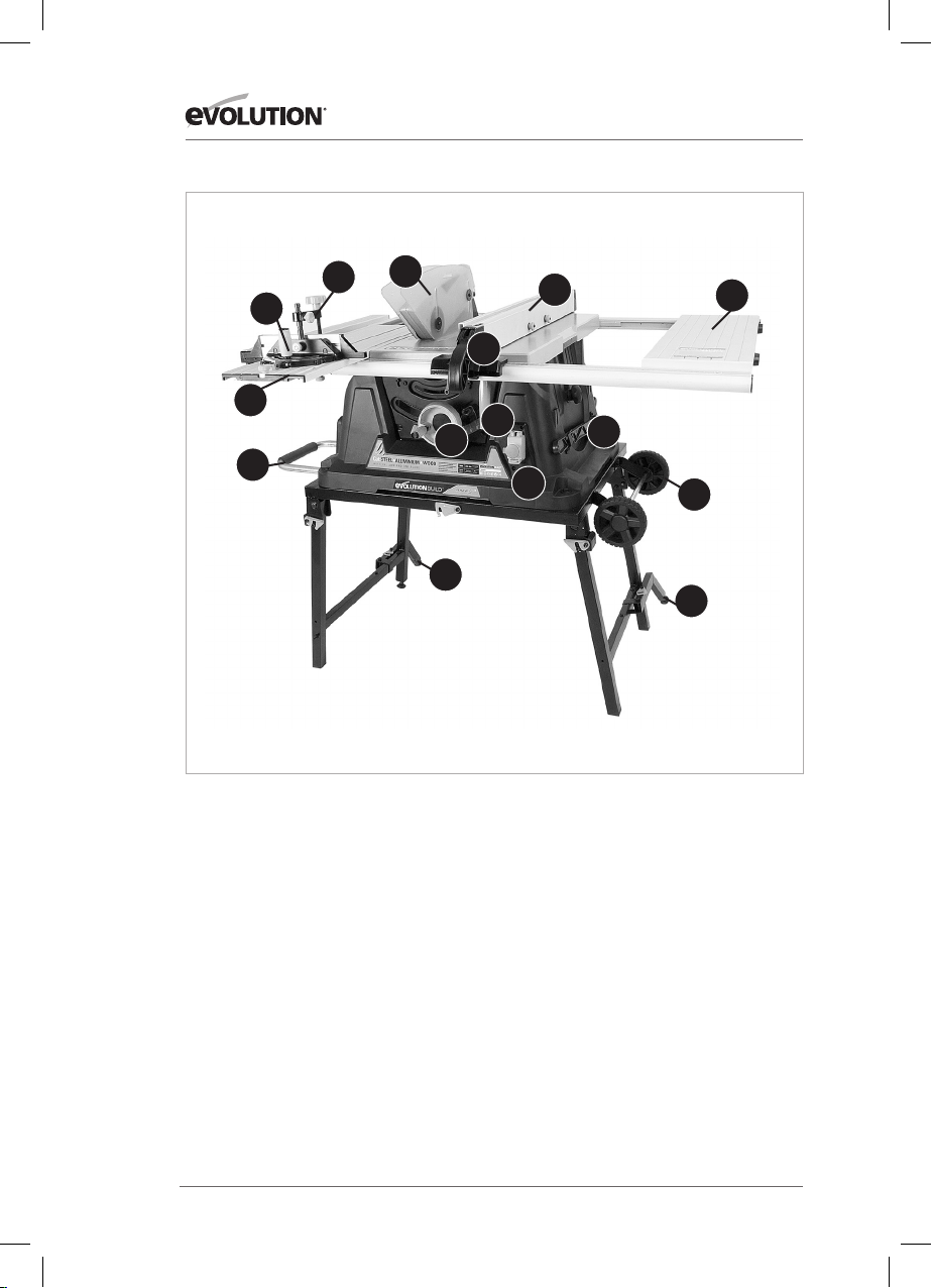
MACHINE OVERVIEW OF EVOLUTION 255mm (10˝) RAGE TABLE SAW
9
3
2
7
Know your parts
1. On/Off Switch
2. Sliding Carriage
3. Mitre Gauge
4. Blade Guard
5. Rip Fence
6. Rip Fence Locking Handle
7. Transportation Handle
8. Transportation Wheels
9. Hold Down Clamp
10. Dual Function Adjustment Handle
11. RH Table Extension
12. RH Table Locking Lever
13. Push Stick
14. Rear Cantilever Braces
4
14
10
5
6
12
1
13
11
8
14
10
Page 11
www.evolutionpowertools.com
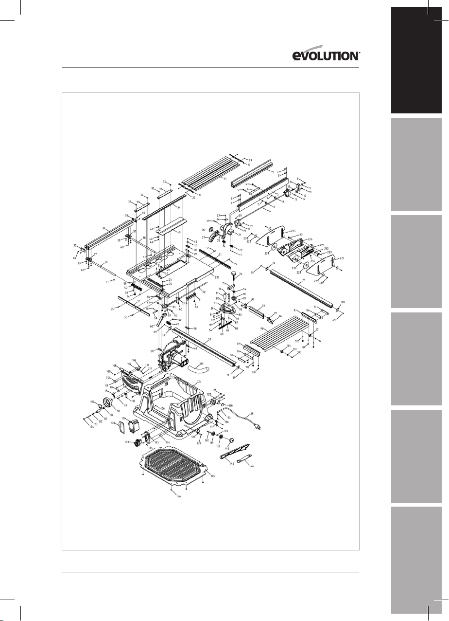
PARTS DIAGRAM Parts Diagrams can also be downloaded from www.evolutionpowertools.com
EN
DE
ES
11
FR
IT
NL
Page 12
www.evolutionpowertools.com
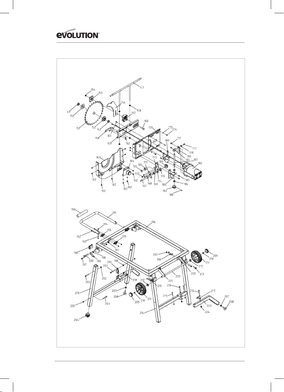
PARTS DIAGRAM Parts Diagrams can also be downloaded from www.evolutionpowertools.com
12
Page 13
www.evolutionpowertools.com
ASSEMBLY & OPERATION
Note: Some minor assembly is required to prepare this machine
for use. Please refer to the Service Parts Diagram.
Some of the following tasks can be carried out with the machine
still in its packaging if desired.
WARNING: Do not connect this machine to a power supply until
assembly has been completed, and a thorough safety check of the
machine and all of its systems has been carried out.
Check that all the contents (as listed in this Instruction Manual)
are present.
Follow these instructions if the leg set and plastic lower safety
guard are fastened to the machine.
• Read and understand these instructions.
• Visually check the inside of the machine body to locate any
polystyrene transit packing. This polystyrene is present to
provide protection for the machines internal components
during shipping. It is not required operationally and must be
removed before the machine can be used.
• Remove 6 of the 8 cross-head screws which fasten the lower
plastic safety guard to the body of the machine.
The 2 screws positioned underneath the sliding
transportation handle can be left in place.
• Carefully ease the guard upwards to gain access to the inside
of the machine.
• Reach inside and remove any transit packing present.
• Replace the lower plastic safety guard and replace the 6
cross-head screws.
• Remove the machine from the packaging.
EN
DE
ES
FR
WARNING: This machine is heavy. Enlist competent help
when removing this machine from its packaging.
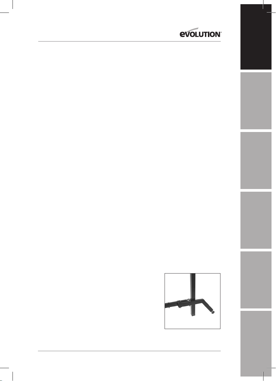
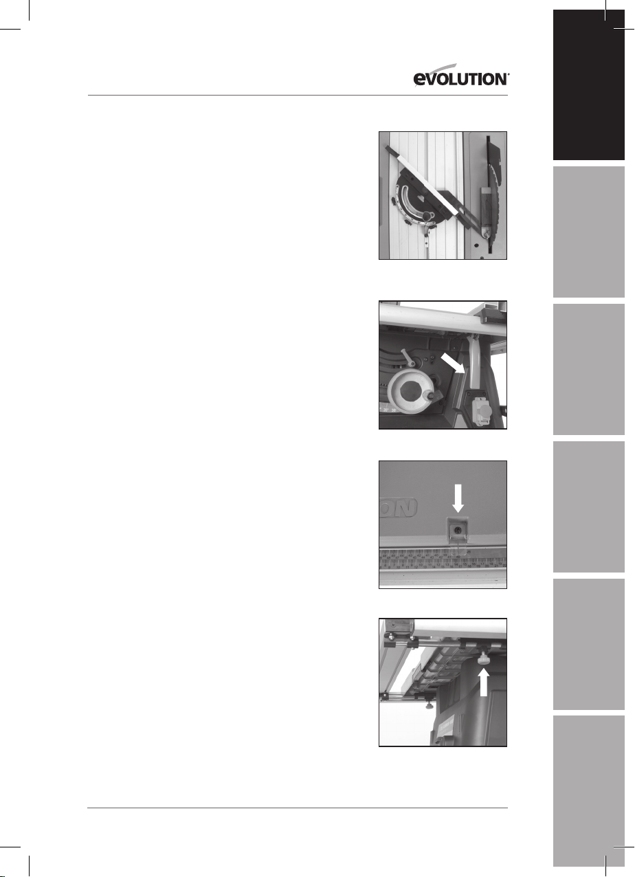
1. Deploying the Legs
The legs are stored underneath the machines main body.
• Release the retaining hook found to the front of the machine.
• Swing the legs outwards
• Secure the legs by hooking the safety hook over the
protruding metal screw.
• Unhook and deploy the 2 rear cantilever braces and
re-hook them into their operational position. (Fig. 1)
Note: The cantilever braces, and one of the main legs have
an adjustable foot which can be screwed in or out to obtain
maximum stability for the machine, particularly on uneven
surfaces.
13
FIG. 1
IT
NL
Page 14
ASSEMBLY & OPERATION
FIG. 2
FIG. 3
3-5mm
www.evolutionpowertools.com
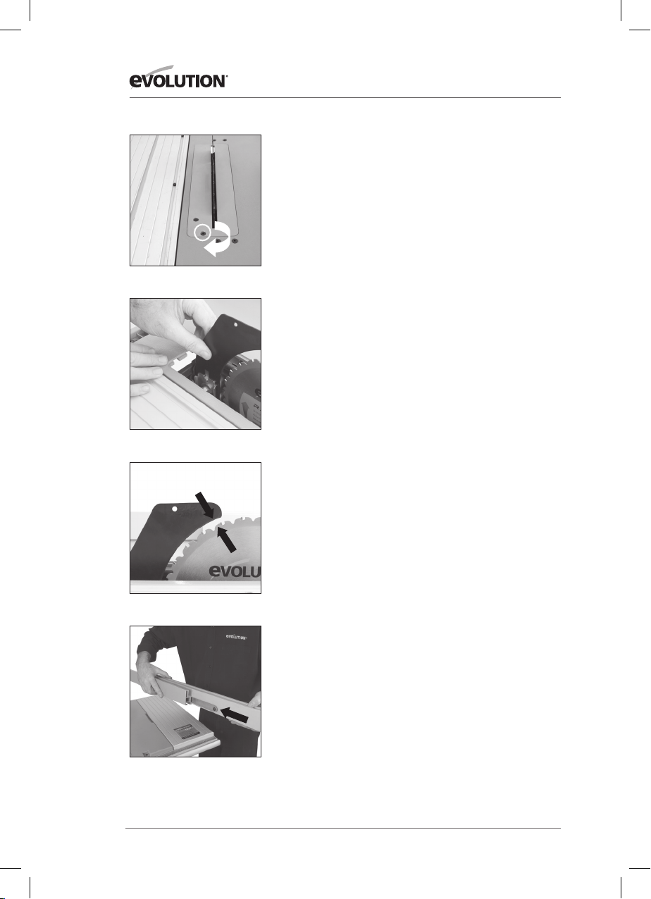
2. Fitting the Riving Knife
WARNING: Ensure that this procedure is only carried out with
the machine disconnected from the mains supply.
The Riving Knife is a very important component, and must be
fitted correctly. The Riving Knife has two functions:
• It prevents the workpiece from binding as it passes through
the blade.
• It provides a suitable connection point for the blade guard.
To fit the Riving Knife:
• Remove the table insert by rotating its fixing screw (Fig 2)
approx 1/4 turn.Lift & slide the table insert from the table.
• Raise the blade to its highest position. (see Operations 2)
• Loosen the Riving Knife fixing bolt by several turns.
• Slide the Riving Knife (it is slotted for convenience) between
the fixing plate and mounting block. (Fig. 3) Ensure that the
mounting blocks projecting lugs engage with the slot in the
Riving Knife.
• Adjust the Riving Knife so that it is between 3 - 5mm from the
saw blade. (Fig. 4)
• When correct alignment is achieved tighten the fixing bolt.
• Check the saw blade rotates freely and teeth are within
3- 5mm of the Riving Knife.
• Re-install the Table insert.
FIG. 4
FIG. 5
3. The Rip Fence
This machine has a two (2) piece Rip Fence.
The Rip Fence Face Plate must be attached to the Rip Fence.
• Loosen the two thumb nuts to the RH side of the Rip Fence.
• Slide the Rip Fence Face Plate onto the Rip Fence. (Fig. 5)
• Tighten the two thumb nuts.
14
Page 15
www.evolutionpowertools.com
ASSEMBLY & OPERATION
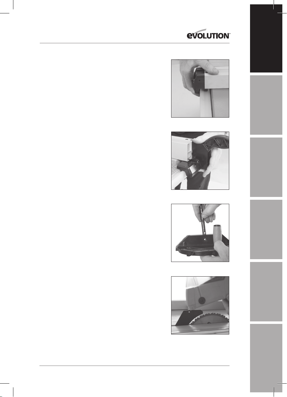
To attach the assembled Rip Fence to the machine:
• Hook the rear of the Rip Fence Guide over the rear Rip
Fence Rail. (Fig. 6A)
• With the handle in its upper position, locate the front of the
Rip Fence over the front Rip Fence Rail. (Fig. 6B) Push the
handle down to lock the Rip Fence in place.
EN
4. The Mitre Gauge
• The Mitre Gauge has an adjustable Face Plate.
• Insert the Hold Down Clamp Pillar into the socket in the Mitre
Gauges main body.
• Ensure that the hole in the Pillar lines up with the hole in the
vertical face of the Mitre Gauge. (Fig. 7)
• Attach the Face Plate to the Mitre Gauge by sliding its
attachment screw through the Mitre Gauges vertical face and
the hole in the Pillar.
• Attach the locking thumb nut to the attachment screw.
• The Mitre Gauge is used on the LH side of the table and runs
in an inverted T slot in the table top.
5. Blade Guard
A fully side shielded blade guard is provided with this machine.
This guard must be attached to the blade riving knife, and the
machine should never be used without this guard in position.
Note: The single hole near the top edge of the riving knife
serves as the attachment point for the Blade Guard.
WARNING: The machine must be disconnected from the
mains supply when installing the blade guard.
To attach the Blade Guard:
• Raise the blade to its full height (Refer to Operations 2) to
fully reveal the riving knife.
• Remove the locating bolt, washer and wing nut from the
Blade Guard assembly.
• Offer the Blade Guard up and onto the riving knife ensuring
that the hole through the Blade Guard assembly lines up with
the hole in the riving knife. (Fig. 8)
• The locating bolt should be inserted through the Blade Guard
assembly and the hole in the riving knife and the washer and
wing nut fitted to one side. The Blade Guard must be able
to move easily and smoothly on the riving knife, so do not
over-tighten this wing nut.
DE
FIG. 6A
ES
FIG. 6B
FR
FIG. 7
IT
15
FIG. 8
NL
Page 16
ASSEMBLY & OPERATION
FIG. 9
FIG. 10
www.evolutionpowertools.com
• Check the operation of the blade guard. Ensure that it is
working efficiently and covers the blade entirely at the sides
as well as the crown.
• Lower the blade a little and recheck that the blade
guard operation.
• When satisfied that the blade guard works throughout the
blades height adjustment range, check that the guard works
equally well with the blade set to a bevel angle. (Fig. 9)
• Check that when the blade is fully lowered, the blade guard
and side covers are in contact with the table top.
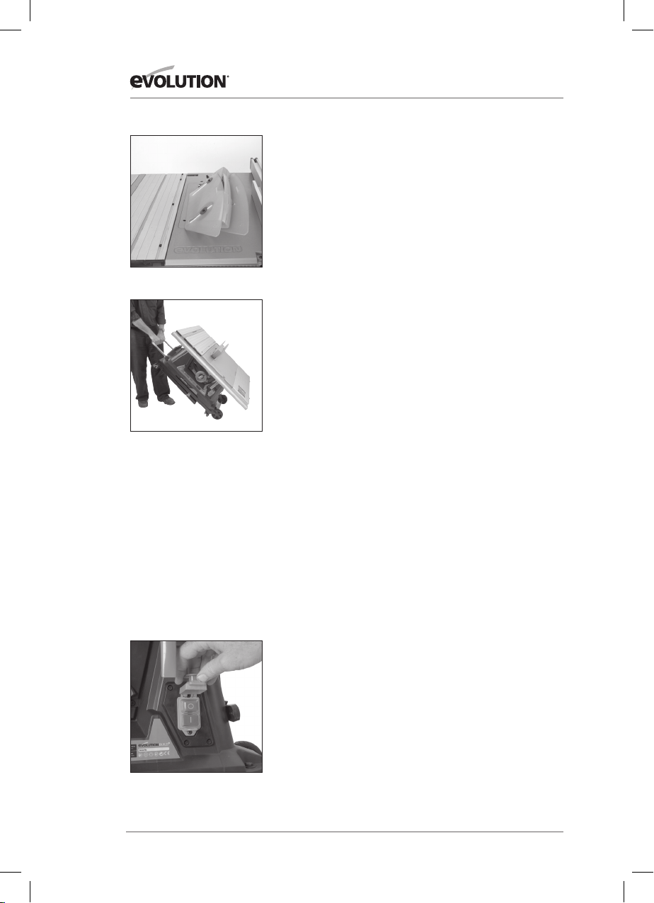
6. Transporting your Table Saw
WARNING: This machine is heavy. Enlist competent help
whenever you have to transport this machine.
1. Ensure that the machine is disconnected from the power
supply and that the power cord is securely stored on the machine.
2. Lower the blade completely into the machine so that the
bottom of the blade guard lies flat on the machine table.
1. Remove and store safely any accessories e.g. mitre gauge, push
stick, rip fence etc that are not secured to the machine.
2. Release the legs and fold them and the cantilever braces
up into the base, securing them with the locking hooks.
Competent help is useful when attempting this and when
lowering the saw to the ground.
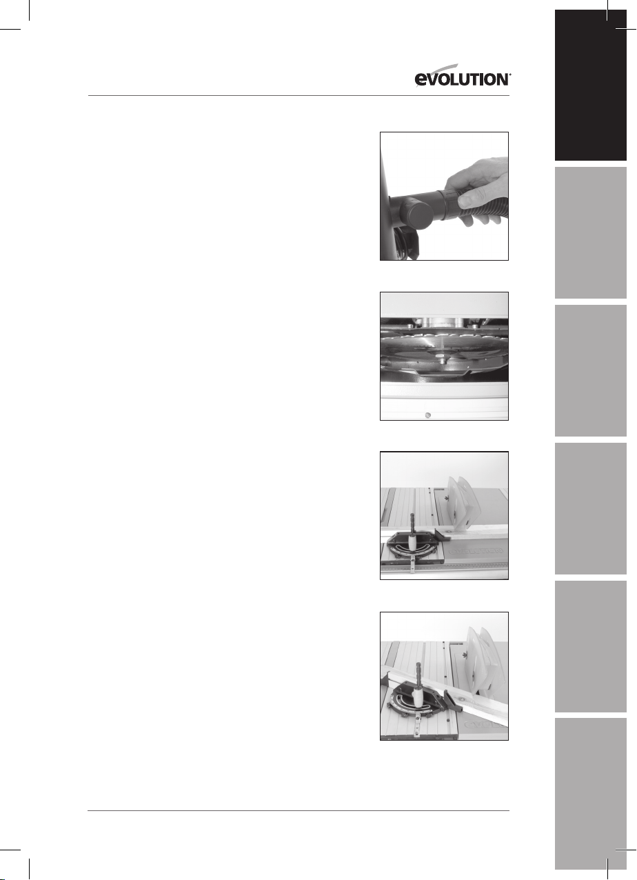
3. Pull out the transportation handle, located at the opposite
side of the saw to the transportation wheels.
4. Lift the handle and allow the machines integral
transportation wheels to touch the ground. (Fig.10)
5. Wheel the machine to its new location.
6. Re-commission the machine and reattach the accessories.
FIG. 11
OPERATIONS
CONTROLS
1. ON/OFF Safety Switch
WARNING: Before operating the ON/OFF switch make sure that
the blade guard is correctly installed and operating properly.
To start the machine, press the tab on LH side of the red safety
button and lift it and the switch cover plate upwards to reveal the
on and off buttons. Push the ‘ON’ button to start the machine and
the ‘OFF’ button to stop the machine. (Fig.11)
WARNING: Never start the machine until all safety checks
and procedures have been carried out.
16
Page 17
www.evolutionpowertools.com
ASSEMBLY & OPERATION
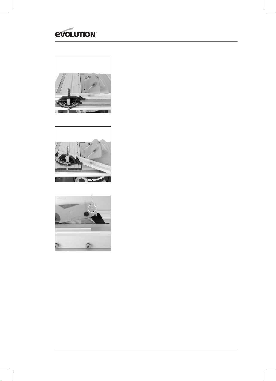
2. Raising/Lowering the blade
WARNING: Only make adjustments to the machine when the
machine is switched OFF and the blade is stationary.
Note: This machine is equipped with a dual function folding
handle hand-wheel. In its ‘normal’ (outer) position the handwheel is used to raise or lower the blade. When the hand-wheel
is pushed in against its bias spring it engages with the curved
toothed rack incorporated in the machines main body. This
allows the hand-wheel to be used to adjust the tilt/bevel angle
of the blade.
To raise or lower the blade:
• Ensure that the hand-wheel is in its ‘normal’ position.
• Turn clockwise to lower the blade. (Fig. 12)
• Turn counter clockwise to raise the blade.
3. Tilting the Blade
The blade can be tilted up to 450 to the left.
• Loosen the tilt locking screw (Fig. 13) by turning the tilt
locking lever.
• Push the hand-wheel in against its bias spring until it
engages the tilt rack.
• Use the hand-wheel to set the required angle. An angle
gauge to aid setting can be found behind the hand-wheel
• Tighten the tilt locking screw when the required angle is
achieved.
• Allow the hand-wheel to return to its ‘normal’ position.
EN
DE
FIG. 12
ES
FIG. 13
FR
Note: The tilt locking lever is sprung loaded and adjustable.
This enables the lever to be repositioned on the locking screw.
• Pull out the lever and move to the desired position.
• Release the lever and allow the spring to re-seat the lever.
Repositioning may be necessary to avoid fouling the machines
hand-wheel when the blade is tilted.
17
IT
NL
Page 18
ASSEMBLY & OPERATION
FIG. 14
FIG. 15
www.evolutionpowertools.com
4. Rip Fence Guide
This machine is fitted with a two piece Rip Fence. We recommend
that the Rip Fence is normally used in conjunction with its
adjustable Face piece.
The Rip Fence should be positioned to the RH side of the blade
and is locked in position by using the locking lever. Push down to
lock, and pull up to unlock.
When repositioning the Rip Fence use the mid-point of the fence
to push or pull the fence to the desired position.
(Fig. 14) Using the mid-point aids accuracy and speed of setting.
The clamping system is designed to correctly align the fence
when the locking lever is pushed down.
Check alignment by sighting either side of the fence with any of
the ‘ lines’ that run across the table.
If misalignment is suspected, the pressure being applied by the
Rip Fence locking lever could be at fault.
To adjust the locking lever pressure:
• Ensure that the locking lever is in the unlocked position.
• Turn the clamp pressure adjustment nut (Fig. 15) one flat
either clockwise or counter-clockwise.
• Recheck Rip Fence operation and alignment.
• Continue nut adjustment until the Rip Fence operation is
satisfactory and alignment and clamping is always achieved
wherever the fence is positioned.
FIG. 16
FIG. 17
Note: The Rip Fence guide incorporates a ‘transparent window’
with a datum line to aid reading the measurement scale found
on the fence rail. (Fig. 16)
Forwards and backwards adjustment of the Rip Fence Face is
possible. Loosen the two thumb nuts and slide the aluminium
Fence Face extrusion to the desired position. Tighten the thumb
nuts securely.
Note: We recommend that normally the Rip Fence Face be
adjusted so that the rear of the Fence Face is level with the rear
of the blade where it emerges from the table. This will provide
clearance for the workpiece as it passes the blade.
The Rip Fence Face has a ‘Hi’ and ‘Lo’ position. The ‘Lo’ position
can be very useful when cutting thin sheet material as it gives
the operator a better view of the workpiece as it passes through
the blade. (Fig.17)
18
Page 19
www.evolutionpowertools.com
ASSEMBLY & OPERATION
To reposition the Rip Fence Face:
• Loosen the two thumb nuts to the RH side of the Rip Fence.
• Slide out the Rip Fence Face extrusion.
• Re-attach the Rip Fence Face in the ‘Lo’ position.
• Adjust to suit and tighten the two thumb nuts.
• Return to the normal ‘Hi’ position when cutting has been
completed.
5. Mitre Gauge
The mitre gauge is used on the LH side of the table and runs in
an inverted T slot in the sliding carriage table top.
Turn the vertical handle counter-clockwise to unlock the mitre
gauge, and adjust to the required mitre angle. Turn the handle
clockwise to lock the mitre gauge at the chosen angle.
Note: We recommend that the Mitre Gauge Slide Locking screw
(Fig. 18) be removed and stored safely off the machine for future
use when the Mitre Gauge is being used with the sliding carriage
in the ‘locked’ position.
We further recommend that the Hold Down Clamp be removed
from the Mitre Gauge and stored safely when the machine is being
used with the sliding carriage in the ‘locked’ position.
Note: The extruded aluminium face plate of the mitre gauge
should be adjusted so that it is close to, but does not foul the
blade guard. Adjust by loosening the finger nut and sliding the
faceplate to the required position. Securely tighten the thumb
nut. (Fig. 19)
EN
DE
FIG. 18
ES
FIG. 19
FR
The Mitre Gauge can be set at any angle between 600 Left and
600 Right.
Fast index positions are incorporated into the design for 900,
450 L and 450R.
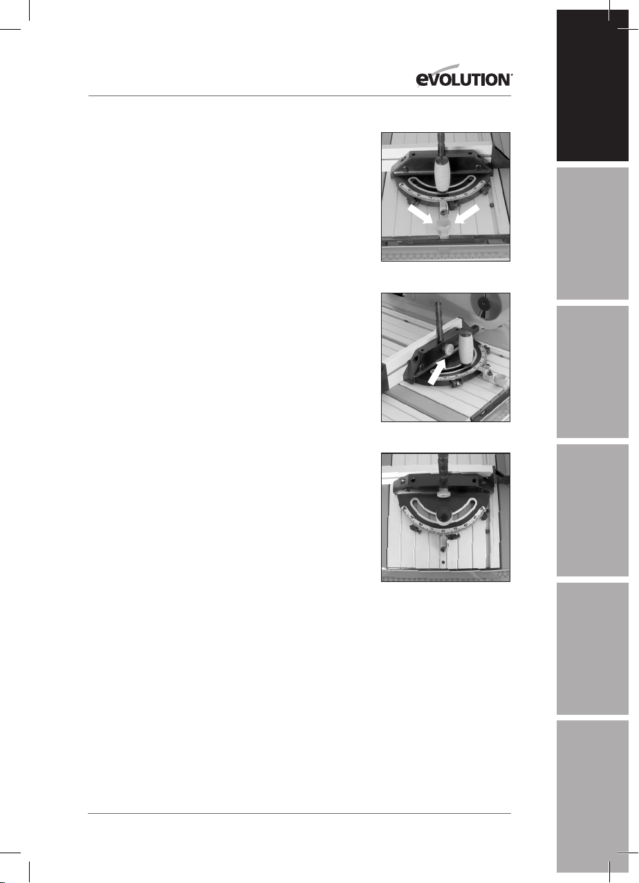
To use the Fast Index facility:
0
• 90
- Ensure that the ‘stop plate’ is in the down position and the
900 index screw is resting against its RH side. (Fig. 20)
0
• 45
L - Open the ‘stop plate’ by pivoting it upwards. Loosen the
vertical locking handle and rotate the Mitre Gauge so that the 450
L index screw just passes through the ‘stop plate’. Close the ‘stop
plate’ and bring the 450 L index screw to rest against the RH side of
the closed ‘stop plate’. Tighten the handle
0
• 45
R - Open the ‘stop plate’ by pivoting it upwards. Loosen the
vertical locking handle and rotate the Mitre Gauge so that the
900 index screw passes through the ‘stop plate’.
• Close the ‘stop plate’ and bring the 45
against the RH side of the ‘stop plate’.
0
R index screw to rest
19
FIG. 20
IT
NL
Page 20
ASSEMBLY & OPERATION
FIG. 21
FIG. 22
www.evolutionpowertools.com
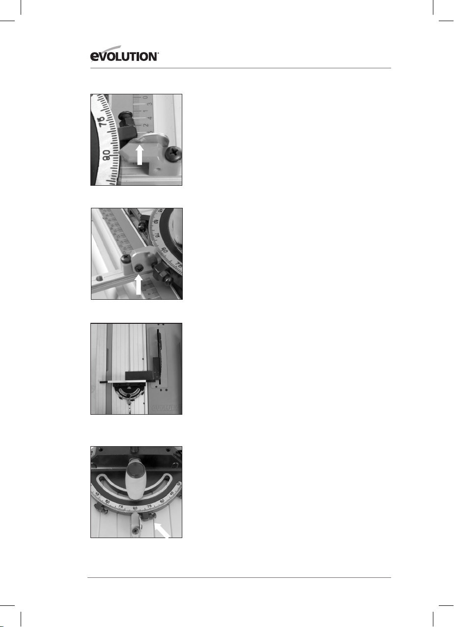
Note: Each of the fast index screws has been factory set for
angular accuracy. All the index screws can be adjusted if
necessary.
The ‘stop plate’ should rotate easily. It is important that the
punched swage on the plate (Fig. 21) which prevents it from
being over-rotated and potentially fouling the ‘T’ slot be
checked and adjusted.
To check and adjust the ‘stop plate’:
• Rotate the ‘stop plate’ forward.
• Visually check that the punched swage is resting upon the
plastic index pointer preventing over-rotation.
• If necessary adjust the ‘stop plate’ mounting screw so that
plate moves easily and the swage always rests upon but
cannot slide past the plastic index pointer. (Fig. 22)
Index Screw Checking and Adjustment
To check the accuracy of the angular settings the operator will
require an Engineers Square and a 450 Square. (Not supplied)
WARNING: Only carry out these procedures with the machine
disconnected from the mains supply.
To Check 900 Setting (Fig. 23)
• Raise the blade to its full height.
• Place the engineers square on the machine table with one
leg resting accurately against the saw blades body.
• Check that the Mitre Gauge is set at 90
0
.
• Slide the Mitre Gauge into its ‘T’ slot and slide it up to the
other leg of the engineers square.
• The Mitre Gauges Face Plate should index precisely with the
engineers square.
FIG. 23
(Blade guard removed for clarity)
FIG. 24
If adjustment is required:
• Loosen the index screws locking nut. (Fig. 24)
• Turn the index screw clockwise or counter-clockwise until
precise alignment with the engineers square is achieved.
• Re-tighten the locking nut.
20
Page 21
www.evolutionpowertools.com
ASSEMBLY & OPERATION
To Check 450 Settings
• Raise the blade to its full height.
• Place the 45
resting accurately against the saw blades body. (Fig. 25)
• Check that the Mitre Gauge is set at one of the 45
0
square on the machine table with one face
0
settings.
• Slide the Mitre Gauge into its ‘T’ slot and slide it up to the
edge of the 450 square.
• The Mitre Gauge Face Plate should index precisely with the
edge of the 450 square.
EN
DE
If adjustment is required follow the instructions as for the
setting of the 900 setting.
6. Multi-Function Table Top
This Table Saw is equipped with a versatile table top capable
of various adjustments which are designed to aid operator
efficiency and safety.
Table extensions
The table can be extended to the RH and to the LH side, to
provide extra workpiece support when necessary. Both sides of
the table can be extended at the same time, or just one side at a
time as required operationally.
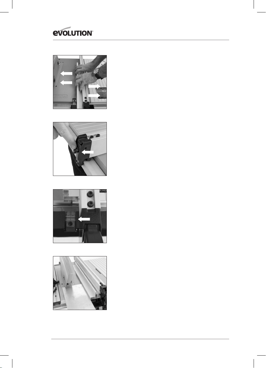
To extend the table to the RH side:
• Pull up the table extension locking lever found just above the
machines ON/OFF switch. (Fig. 26)
• Deploy the table extension to give the required workpiece
support.
• Push the locking lever down to lock the table in the required
position.
• Re-attach and/or adjust the Rip Fence as required.
• When cutting is completed return the table to its original
setting.
Note: The Fence Rail will ‘travel’ with the RH table extension
when it is deployed. A window with datum index line is built
into the front edge of the table to aid setting. (Fig. 27)
FIG. 25
(Blade guard removed for clarity)
ES
FIG. 26
FR
FIG. 27
IT
To extend the table to the LH side:
• Loosen the two locking knobs (one to the front and one
to the rear of the machine) underneath the LH side of the
machines table. (Fig. 28)
• Deploy the table extension.
• Tighten the locking knobs.
• When cutting is completed return the table to its original
setting.
21
FIG. 28
NL
Page 22

ASSEMBLY & OPERATION
FIG. 29
www.evolutionpowertools.com
Sliding Carriage System
This machine is fitted with a Sliding Carriage to the LH side of
the blade. This facility can be particularly useful when crosscutting small section material such as metal box-section or
extrusions etc.
The sliding carriage should always be used with the Mitre
Gauge locked to it in the desired position.
Material can be clamped to the Sliding Carriage by using
the Mitre Gauge with its Hold Down Clamp, thus enhancing
operator control and safety.
The sliding carriage system can also be very useful (when used
in conjunction with a locked on Mitre Gauge) for repetitive
cross-cutting.
To Release the Sliding Carriage
WARNING: The machine must be switched off, the blade
stationary, and the switch cover plate in the closed (safe)
position whenever adjustments etc are being made to the
machine or the workpiece.
The Sliding Carriage Locking Latch is located to the rear of the
machine table and slightly to the LH side of the blade. (Fig. 29)
• Slide the latch to the right to unlock the carriage and pull the
carriage forward.
• When operations are completed, return the carriage to its
original position and slide the locking latch to the left to lock
the carriage.
• Check that the carriage is locked in its ‘locked’ position.
22
Page 23
www.evolutionpowertools.com
ASSEMBLY & OPERATION
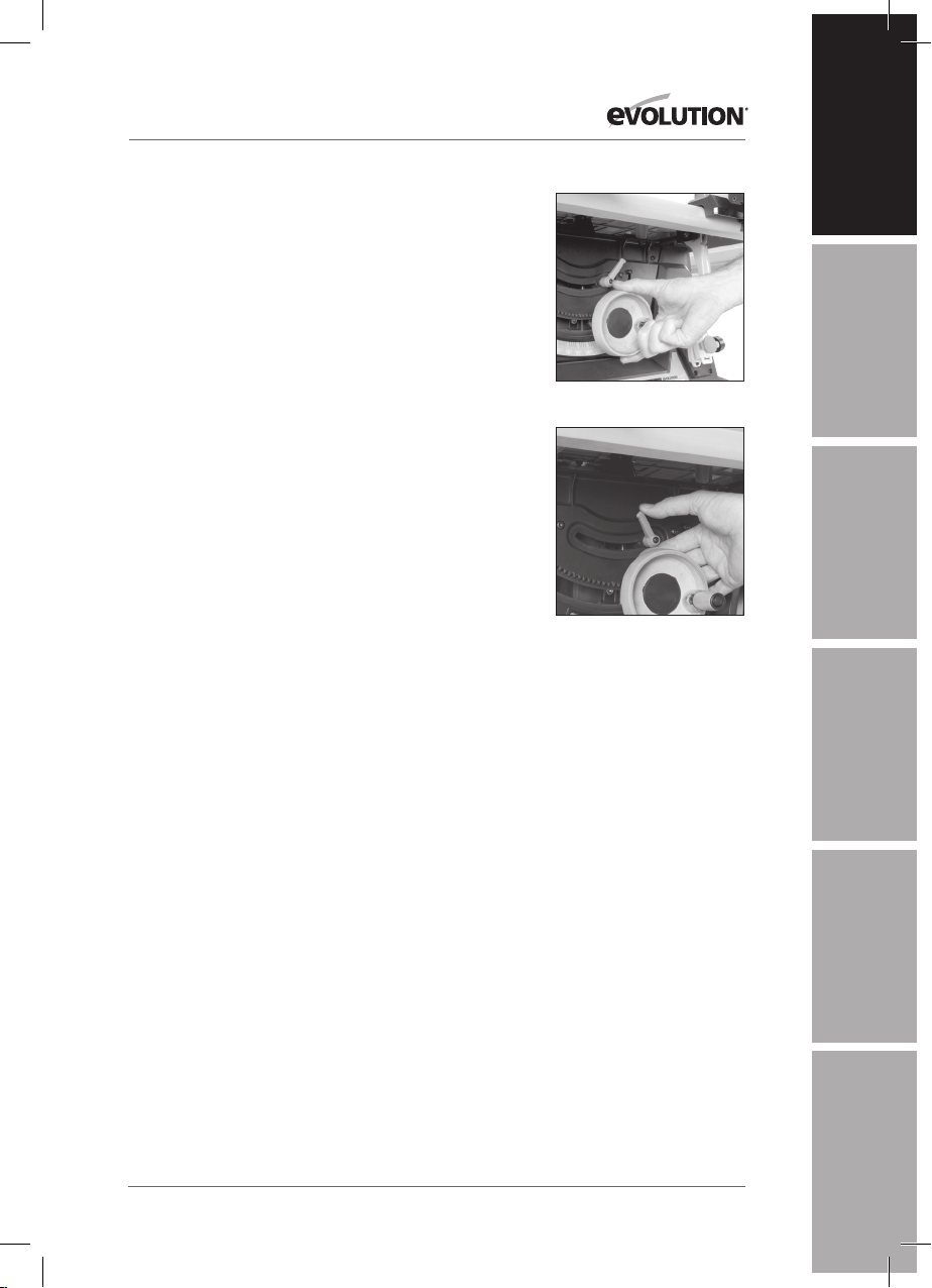
BASIC TABLE SAW OPERATIONS
Multi-purpose blade
The Rage 5 comes fitted with a multi-purpose TCT blade which
is capable of cutting many materials. We recommend that a
workshop dust extraction system is always attached to the
dust extraction port (Fig. 30) when cutting wood or wooden
products to prevent any possible build up of sawdust in the
lower blade guard.
When changing the blade (See Maintenance) the operator
should visually check for any dust build up in the lower blade
guard. With the blade removed any residual dust can be
sucked away using a suitable crevice nozzle vacuum extraction
machine. The blade can then be reinstalled.
Metallic materials should not be cut if it is suspected that
there could be residual sawdust in the lower blade guard. The
machine should be disconnected from its power supply and
the table insert removed (refer to ‘Assembly 2 & 4 Figs 2 & 8 )
so that a visual check can be made. (Fig. 31) If there is evidence
of sawdust build-up, remove this sawdust before commencing
metal cutting operations.
WARNING: Never attempt freehand cuts on this machine.
Always use the appropriate guide or fence to minimise the
possibility of the blade binding and kickback.
EN
DE
FIG. 30
ES
FIG. 31
We recommend that the saw blade protrudes through the
material to be cut by approximately 3mm. Adjust the height of
the blade as previously described. This machine is not suitable
for cutting rebates or stopped grooves.
A workshop dust extraction device should be connected to the
extraction port found at the rear of the machine. (Fig. 30)
1. Crosscutting
Set the mitre gauge to 900 and tighten using the vertical
handle. Position in the ‘T’ slot and adjust the mitre face plate as
previously described. Index the material to be cut against the
mitre gauge faceplate. Switch on the saw and allow to reach full
operating speed before sliding the mitre gauge and workpiece
towards the rear of the table making your cut. (Fig. 32)
2. Mitre crosscutting
Mitre crosscutting is cutting the material at an angle other
than 900. Set the mitre gauge to the desired angle, tighten and
proceed as cross-cutting above. (Fig. 33)
23
FR
FIG. 32
IT
FIG. 33
NL
Page 24
ASSEMBLY & OPERATION
FIG. 34
www.evolutionpowertools.com
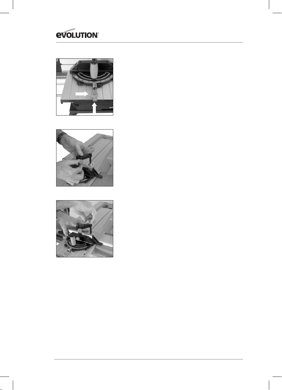
3. Bevel crosscutting
Bevel crosscutting is the same as crosscutting but with the
blade tilted at an angle. Tilt the blade to the desired angle as
previously described, and ensure that it is locked in place.
Set the mitre gauge to 900 and adjust the faceplate so that it
does not touch or foul the saw blade as it passes. Index the
material against the mitre gauge and make your cut. (Fig. 34)
4. Compound mitre cutting
Compound mitre cutting is a combination of mitre cutting and
bevel crosscutting.
Adjust the mitre gauge and the blade to the desired angles.
Lock both in place.
Check that the mitre gauge will pass the saw blade without
fouling. Adjust the mitre gauge faceplate if necessary.
Index the material against the mitre gauge and make your cut.
(Fig. 35)
5. Repetitive crosscutting
Repetitive cutting is cutting a number of pieces to the same
length without having to mark out each piece.
FIG. 35
FIG. 36
Note: Repetitive cross-cutting is carried out with the mitre
gauge positioned on the LH side of the machine, with the rip
fence on the RH side of the machine.
Caution: The Rip Fence can be used as a length stop only if it
is properly set and adjusted.
To use the Rip Fence as length stop align the back of the
adjustable Fence Face with the back of the saw blade and set at
the required distance from the blade. This will allow clearance
for the material as it passes through the saw blade. (Fig. 36)
• Check that the Rip Fence is set at the required distance and is
lying parallel to the saw blade.
• Index the material to be cut against the Mitre Gauge and the
Rip Fence Face.
• Hold the material and Mitre Gauge with your left hand.
• Gently push the workpiece through the saw. Use a push stick
in your right hand to guide the workpiece on the RH side of
the blade.
Note: If the Sliding Carriage system is deployed for repetitive crosscutting, the Mitre Gauge must be fastened to the carriage.
We recommend that the mitre gauge be fixed in its dedicated
position to the front of the carriage, where the locking screw will
engage in a hole in the sliding carriage body.
24
Page 25

www.evolutionpowertools.com
ASSEMBLY & OPERATION
6. Rip cutting
Rip cutting is cutting along the length of a piece of material
rather than across it. Rip cutting should always be done with the
Rip Fence Face set to the desired width and on the RH side of
the machines table.
The mitre gauge is not required for this operation, and should
be stored safely off the machine for future use.
Note: Check that the Rip Fence is locked in position and is
parallel to the saw blade.
Check that the riving knife is properly aligned with the saw blade.
When ripping small section material a push stick should be used
to feed/guide the final 300mm of the material past the blade. A
push stick should always be used when making cuts of less than
300mm.
When ripping long boards or large panels always use a remote
work support or enlist trained competent help.
Feed the workpiece through the saw keeping it indexed against
the rip fence. Use smooth, steady pressure and employ a push
stick if necessary. (Fig. 37)
When the ripping width is greater than 300mm, and with care,
both hands can be used to guide/feed the material through the
saw. The operators left hand will be to the LH side of the saw
blade. The operators right hand will be close to the rip fence on
the RH side of the sawblade. Hands should never be in line with
the blade.
EN
DE
FIG. 37
ES
FR
7. Bevel ripping
When bevel ripping material 150mm or narrower use the rip
fence on the RH side of the blade only.
8. Using the Sliding Carriage System
WARNING: All ‘setting up’ operations should be undertaken
with the machine switched off, the blade stationary, and the
switch cover plate in the closed (safe) position.
Release the carriage by sliding the table latch (located at the
rear of the table and just to the LH of the blade) to the
unlocked position.
• Set the Mitre Gauge to the required angle and lock in place
with the vertical locking handle.
• Slide the Mitre Gauge into the inverted ‘T’ slot and lock in the
required place by tightening the locking knob.
25
IT
NL
Page 26
ASSEMBLY & OPERATION
FIG. 38
FIG. 39
www.evolutionpowertools.com
Note: Although the Mitre Gauge can be locked in any desired
position along the ‘T’ slot it does have a dedicated position to
the front of the carriage, where the locking screw will engage in
a hole in the sliding carriage body. (Fig. 38)
• Install the Hold Down Clamp, if required, onto the pillar fitted
into the Mitre Gauges main body. (Fig. 39) Tighten in the
required position using the locking screw.
• Place the workpiece in the required position and against the
Mitre Gauge Face Plate.
• Clamp the workpiece to the Sliding Carriage by adjusting the
Hold Down Clamp for best position and tightening the vertical
locking screw using the large knob. (Fig. 40)
• The Mitre Gauge has its own locking screw to lock it to the
sliding carriage, but when used with the Hold Down Clamp,
additional security is obtained. Check the integrity of the
installation.
Note: We recommend that the above set up procedure is
completed with the Sliding Carriage pulled out from the
machine table to give the operator the clearance and space to
make any measurements, confirm cutting lines etc.
When satisfied that all adjustments and cutting line positionings
etc are correct, and all adjustment screws are securely
tightened, open the On/Off switch cover plate.
Start the machine and push the Sliding Carriage (by using the
Mitre Gauge) to the rear of the Table to make the cut.
FIG. 40
26
Page 27
www.evolutionpowertools.com
ASSEMBLY & OPERATION
WARNING: Ensure that the machine is disconnected from
the mains supply before any maintenance tasks or adjustments
are attempted.
CHANGING THE BLADE
EN
Note: We recommend that the operator considers wearing
protective gloves when handling or changing the machines blade.
1. Disconnect the machine from the power supply
2. Remove the blade guard. (Refer to Assembly 4)
3. Remove the table insert by rotating its fixing screw
4. Approximately 1/4 turn. Lift & slide the insert from the table
& safely store it for future use.
5. Raise the blade to its highest position.
6. Use the two blade changing tools provided. One to hold the
motor arbor, and the other to loosen the arbor nut. (Fig. 41)
7. Remove the nut, outer flange and blade.
8. Fit the new blade. Ensure that the teeth are facing to the
front of the saw, and that the arrow on the blade is in line
with the motor direction.
9. Replace the outer flange and nut and tighten securely with
the spanners provided. Check that both blade flanges are in
contact with the blade.
10. Replace the table insert and its fixing screw. Ensure that the
fixing screw is correctly seated.
11. Replace the blade guard and check all operational functions
of the blade and its guarding system.
12. Only connect the machine to its main supply after a
complete safety check of the machine has been carried out.
Cleaning
After each use the machine should be cleaned. Remove all
sawdust etc from the visible parts of the machine with a vacuum
cleaner. A vacuum cleaner can also be connected to the machine
dust extraction port at the rear of the machine. This should
remove debris from the inside of the machine. Never use solvents
to clean plastic parts, as solvents can damage them. Clean only
with a soft very slightly damp cloth.
DE
FIG. 41
ES
FR
IT
Riving Knife
The riving knife is a very important component and must be
fitted correctly aligned and adjusted. The riving knife prevents the
work from binding as it passes through the blade.
Inspect the riving knife at regular intervals and replace it if it is
worn or damaged.
27
NL
Page 28

MAINTENANCE
www.evolutionpowertools.com
Note: Use only a genuine Evolution Riving Knife, as this is a
dedicated component for this machine. Non genuine parts could
be dangerous. If in any doubt, please contact the Helpline.
Push Stick
A plastic push stick is provided with the machine and has its
own dedicated storage brackets to the RH side of the machines
main body. (Fig. 42) When not in use store the push stick on
the machine.
FIG. 42
FIG. 43
Note: If the push stick becomes damaged it should be replaced. If the
operator makes their own push stick, we recommend that it follows
the same pattern as that supplied. Replacement push sticks are
available from Evolution Power Tools.
Blade Storage
A blade storage facility is available at the RH side of the
machine. (Fig. 43) Undo the centre hand nut and place any
spare blades onto the ø25.4mm metal flange. Secure the blades
with the centre hand nut.
28
Page 29

www.evolutionpowertools.com
ENVIRONMENTAL PROTECTION
Waste electrical products should not be disposed of with
household waste. Please recycle where facilities exist. Check
with your Local Authority or retailer for recycling advice.
EN
TROUBLE SHOOTING GUIDE
CONDITION POSSIBLE CAUSE ACTION
Machine will not start. Plug removed from outlet
socket or outlet socket
not switched ‘on’.
Sliding Carriage will
not move.
Left Hand Table Extension
will not deploy.
Blade will not rise or fall. Dual Purpose Rise and
Sliding Carriage Locking
Latch still fully or
partially engaged.
One or both (usually
the rear) of the under-table
locking knobs not
l oosened.
Fall Handle partially engaged
with curved toothed rack.
Replace plug and/or switch
‘on’ the outlet socket.
Ensure that the Carriage
Locking Latch is completely
disengaged by sliding it
fully to the right.
Ensure that both locking
knobs are sufficiently
loosened. Deploy the table
extension and retighten both
under-table locking knobs.
Ensure that the Handle is
in its outer position. Pull the
Handle out from the machine
slightly to confirm it is deployed
in the outer position.
DE
ES
FR
Blade will not tilt. Tilt Locking Screw
not loosened.
Blade Guard does not
adjust automatically.
Over -tightened rear fixing
screw and wingnut.
29
Loosen the Tilt Locking Screw.
Tilt the blade to the desired
angle and then retighten the
locking screw
Loosen wingnut slightly until
Blade Guard operation is
smooth and satisfactory.
IT
NL
Page 30

www.evolutionpowertools.com
EC DECLARATION OF CONFORMITY
In accordance with EN ISO 17050-1:2004
The manufacturer of the product covered by this Declaration is:
Evolution Power Tools, Venture One, Longacre Close, Holbrook Industrial Estate, Sheeld, S20 3FR
The manufacturer hereby declares that the machine as detailed in this declaration fulls all the
relevant provisions of the Machinery Directive and other appropriate directives as detailed below.
The manufacture further declares that the machine as detailed in this declaration, where
applicable, fulls the relevant provisions of the Essential Health and Safety requirements.
The Directives covered by this Declaration are as detailed below:
2006/42/EC. Machinery Directive.
2006/95/EC. Low Voltage Equipment Directive.
2004/108/EC. Electromagnetic Compatibility Directive.
93/68/EC. The CE Marking Directive.
2011/65/EU. The Restriction of the Use of certain Hazardous
Substances in Electrical Equipment (RoHS) Directive
2002/96/EC The Waste Electrical and Electronic Equipment (WEEE) Directive.
as amended
by 2003/108/EC.
And is in conformity with the applicable requirements of the following documents:
EN55014-1:2006+A1 • EN55014-2:1997+A1+A2 • EN61000-3-2:2006+A1+A2
EN61000-3-3:2008 • EN61029-1:2009+A11 • EN61029-2-1:2010
Product Details
Description: 255mm 10” TCT MULTIPURPOSE TABLE SAW
Evolution Model No: RAGE52551, RAGE52552, RAGE52552EU
Brand Name: EVOLUTION
Voltage: 110V - 230-240V
Input: 50Hz
The technical documentation required to demonstrate that the product meets the requirements
of directive has been compiled and is available for inspection by the relevant enforcement
authorities, and veries that our technical le contains the documents listed above and that
they are the correct standards for the product as detailed above.
Name and address of technical documentation holder.
Signed: Print: Steven Bulloss: Operations Director
Signed: Print: Lettie Lui: Product Manager
Date: 18/04/2011
30
Page 31

www.evolutionpowertools.com
NOTES
EN
DE
ES
31
FR
IT
NL
Page 32

®
Page 33

DEUTSCH
Übersetzung Original Bedienungsanleitungen
EN
ES
FR
NL
IT
Page 34

www.evolutionpowertools.com
TABLE OF CONTENTS
English Page 02
Deutsch Seite 32
Español Página 68
Français Page 104
Italiano Pagina 140
Nederlands Pagina 176
Wichtiger Hinweis
Garantie
Technische Daten
Etiketten und Symbole
Allgemeine Sicherheitshinweise
Sicherheitshinweise für alle Sägen
Zusätzliche spezifische Sicherheitshinweise
Überblick über die Säge
Explosionszeichnung der Einzelteile
Zusammenbau
Betrieb
Wartung
Umweltschutz
EG-Konformitätserklärung
Probleme Zu Schießen Führung Page 67
Page 35
Page 35
Page 36
Page 37
Page 38
Page 39
Page 40
Page 42
Page 45
Page 47
Page 48
Page 65
Page 65
Page 66
34
Page 35

www.evolutionpowertools.com
EN
WICHTIG
Bitte lesen Sie diese Betriebsanleitung und die
Sicherheitshinweise sorgfältig und vollständig.
Zu Ihrer eigenen Sicherheit, wenn Sie unsicher
über irgendeinen Aspekt der Verwendung dieser
Ausrüstung sind, bitte auf das entsprechende
Technische Helpline, kann die Anzahl der dem
auf die Evolution Power Tools Website gefunden
werden. Wir betreiben mehrere Helplines in
unserer weltweiten Organisation, sondern
Technische Hilfe ist auch von Ihren Lieferanten.
WEB
www.evolutionpowertools.com / register
EMAIL
info@evolutionpowertools.com
Herzlichen Glückwunsch zum Kauf eines
Evolution Power Tools Machine. Bitte füllen
Sie Ihre Produktregistrierung ‘online’, wie in
der A4 Online Garantie Registrierung Faltblatt
mit dieser Maschine erklärt. Sie können
auch scannen den QR-Code auf der A4
Faltblatt mit einem Smart Phone gefunden.
Dies ermöglicht es Ihnen, Ihre Maschine
Garantiezeit über Evolutions Website durch
die Eingabe Ihrer Daten überprüfen und
sorgen so für schnellen Service, wenn es
notwendig. Wir danken Ihnen für die Auswahl
eines Produkts aus Evolution Power Tools.
EVOLUTION BEGRENZTE GARANTIE.
Evolution Power Tools behält sich das Recht
vor, Verbesserungen und Änderungen an
der Produktentwicklung ohne vorherige
Ankündigung vorzunehmen.
Bitte beachten Sie die GarantieRegistrierung Broschüre und / oder der
Verpackung Details zu den Bedingungen
und Konditionen der Garantie.
Evolution Power Tools wird, innerhalb der
Garantiezeit, und aus dem ursprünglichen
Kaufdatum, reparieren oder ersetzen Ware
mangelhaft befunden werden Material-oder
Herstellungsfehler. Diese Garantie ist ungültig,
wenn das Werkzeug zurückgegeben hat über
die Empfehlungen in der Bedienungsanleitung
oder wenn die Maschine durch einen Unfall,
Vernachlässigung oder unsachgemäße
Wartung beschädigt worden.
Diese Garantie gilt nicht für Maschinen und
/ oder Komponenten, die verändert wurden,
geändert oder in irgendeiner Weise verändert
oder ausgesetzt über die empfohlenen
Kapazitäten und Spezifikationen verwenden,
gelten. Elektrische Bauteile unterliegen
den jeweiligen Herstellergarantien. Alle
fehlerhaften Waren frachtfrei gilt für Evolution
Power Tools zurückgegeben werden. Evolution
Power Tools behält sich das Recht vor,
wahlweise reparieren oder ersetzen Sie es mit
dem gleichen oder gleichwertigen Artikel.
Es gibt keine Garantie - schriftlich oder
mündlich - für Verbrauchsmaterial Zubehör
wie (Liste ist nicht abschließend) Messer, Fräser,
Bohrer, Meißel oder Paddel etc. In keinem Fall
ist Evolution Power Tools Haftung für Verluste
oder Schäden, die direkt oder indirekt aus der
Verwendung unserer Ware oder aus einem
anderen Grund. Evolution Power Tools haftet
nicht für irgendwelche Kosten auf solche Waren
oder Folgeschäden verantwortlich. Kein leitender
Angestellter, Mitarbeiter oder Vertreter von
Evolution Power Tools ist berechtigt, mündliche
Erklärungen von Fitness zu machen oder einem
der vorhergehenden Verkaufs verzichten und
niemand wird verbindlich Evolution Power Tools.
Fragen im Zusammenhang mit dieser
beschränkten Garantiesollte das Unternehmen
den Kopf gerichtet werdenBüro , oder rufen Sie
die entsprechende Nummer Helpline.
DE
ES
FR
IT
NL
35
Page 36

www.evolutionpowertools.com
TECHNISCHE DATEN
MACHINE METRISCH IMPERIAL
Motor UK/EU: 230-240V ~ 50Hz (S6 40%) 1800W 8A
Motor UK:
110V
~ 50Hz 1600W 15A
Tabelle Abmessungen 656 x 1260mm 26 x 49-5/8”
Drehzahl (Leerlauf) 2500min
-1
2500rpm
EINSCHNITTSKAPAZITÄTEN
Mild Steel Plate - Max Dicke 6mm 1/4”
Wood - Maximale Schnitttiefe bei 90
Wood - Maximale Schnitttiefe bei 45
0
0
80mm 3-1/8˝
55mm 2-1/8˝
Gewicht 38kg 84lb
Spaltkeil Dicke 1.8mm .070˝
BLADE
Durchmesser 255mm 10˝
Bohrung 25.4mm 1˝
Kerf 2mm .078˝
Zähne 28 28
Max Geschwindigkeit 2750min
-1
2750rpm
NOISE & VIBRATION DATEN
Schalldruckpegel LPA 230-240V - 91.9dB(A)
110V - 90.2dB(A)
Schallleistungspegel LWA 230-240V - 104.5dB(A)
110V - 104.2dB(A)
Unsicherheit K 3dB(A)
36
Page 37

www.evolutionpowertools.com
ETIKETTEN UND SYMBOLE
Symbol Beschreibung
V Volt
A Ampere
Hz Hertz
-1
Min
~ Wechselstrom
n
o
Drehzahl
Leerlaufdrehzahl
Schutzbrille tragen
ETIKETTEN UND SYMBOLE
WARNUNG: Nehmen Sie die Säge nicht in
Betrieb, wenn irgendwelche der Warn- und/oder
Hinweisetiketten fehlen oder beschädigt sind.
Wenden Sie sich an Evolution Power Tools, um
Ersatzetiketten zu erhalten.
Verwenden Sie immer nur OriginalErsatzsägeblätter von Evolution. Nicht zugelassene
Sägeblätter können gefährlich sein! Achten Sie
auf eine sichere Befestigung der Sägeblätter.
Kontrollieren Sie vor jedem Anbringen eines
neuen Sägeblatts auf Vorhandensein von
Verschmutzungen und verwenden Sie keine
stumpfen oder beschädigten Sägeblätter. Prüfen
Sie die Sägeblätter regelmässig auf ihren Zustand
und auf Abnutzung. Beschädigte oder abgenutzte
Sägeblätter müssen sofort ausgewechselt werden.
Lose bzw. beschädigte Schutzvorrichtungen
müssen sofort ausgewechselt werden. Achten Sie
auf ausgeworfene Späne, sie könnten heiss sein.
Treffen Sie immer Vorkehrungen für eine sichere
Handhabung von überschüssigem Material.
EN
DE
ES
Gehörschutz tragen
Nicht berühren
Staubmaske tragen
Lesen Sie die Anweisungen
Warnung
EG-Zertifizierung
Entsorgung elektrischer und
elektronischer Geräte
VIBRATIONSWERT:
Der genannte Vibrationswert wurde in
Übereinstimmung mit einer genormten
Prüfmethode gemessen und eignet sich für
den Vergleich von Geräten miteinander. Der
genannte Vibrationswert kann auch für eine erste
Beurteilung der Exposition verwendet werden.
WARNUNG: Während des tatsächlichen
Betriebs des Elektrowerkzeugs kann der
Vibrationswert je nach der Art der Anwendung
vom angegebenen Wert abweichen. Die
geeigneten Sicherheitsmassnahmen zum Schutz
des Bedieners basieren auf einer Beurteilung der
Exposition unter realen Nutzungsbedingungen,
wobei zusätzlich zur Auslösezeit auch alle
Phasen des Betriebszyklus zu berücksichtigen
sind, wie z. B. die Zeiten, in denen das Werkzeug
ausgeschaltet ist bzw. sich im Leerlauf befindet).
Wenn Sie eine weitere Kopie der
Gebrauchsanweisung benötigen, wenden Sie
sich bitte an Evolution Power Tools unter:
UK: +44 (0)114 251 1022
USA: 1-866-EVO-TOOL
WEB: www.evolutionpowertools.com
37
FR
IT
NL
Page 38

www.evolutionpowertools.com
WICHTIGE SICHERHEITSANWEISUNGEN
Dieses Produkt ist mit einem für das jeweilige
Bestimmungsland zugelassenen Kabel sowie
Stecker ausgerüstet, um die Gefahr von
Stromschlägen zu reduzieren. Nehmen Sie
keinerlei Veränderungen am Kabel oder
Stecker vor.
ALLGEMEINE SICHERHEITSVORSCHRIFTEN
Lesen Sie diese Hinweise sorgfältig durch,
bevor Sie die Säge in Betrieb nehmen.
Bei Nichtbeachtung der nachfolgenden
Anweisungen besteht die Gefahr von
Stromschlag, Brand und/oder schweren
Verletzungen. Bewahren Sie diese Anleitung
zu Nachschlagezwecken auf.
WARNUNG: Bei der Verwendung elektrischer
Werkzeuge sind stets grundlegende
Sicherheitsvorkehrungen zu beachten, um
das Risiko von Bränden, Stromschlägen und
Verletzungen zu reduzieren.
Lesen Sie alle Anweisungen, bevor Sie versuchen,
dieses Produkt in Betrieb zu nehmen, und
bewahren Sie diese Anweisungen auf.
Der Begriff „Elektrowerkzeug“ in den
Warnhinweisen bezieht sich auf Ihr
netzbetriebenes (mit Kabel) oder Ihr
batteriebetriebenes (ohne Kabel)
Elektrowerkzeug.
ICHERHEITSHINWEISE FÜR ALLE SÄGEN
WARNUNG: Bitte lesen Sie alle
Sicherheitshinweise. Bei Nichtbeachtung der
nachfolgenden Hinweise besteht die Gefahr
von Stromschlag, Brand und/oder schweren
Verletzungen.
Bewahren Sie diese Gebrauchsanweisung auf
1. Sicherheit am Arbeitsplatz
a) Sorgen Sie für einen sauberen und gut
beleuchteten Arbeitsplatz. Unordentliche
oder dunkle Bereiche fordern Unfälle
geradezu heraus.
b) Verwenden Sie keine Elektrowerkzeuge
in explosionsgefährdeter Umgebung, in der
sich z. B. brennbare Flüssigkeiten, Gase oder
Stäube befinden. Elektrowerkzeuge erzeugen
Funken, die den Staub oder die Gase entzünden
können.
c) Halten Sie Kinder und Zuschauer während
der Arbeit mit einem Elektrowerkzeug fern.
Ablenkung kann dazu führen, dass Sie die
Kontrolle über das Werkzeug verlieren.
2. Elektrische Sicherheit
a) Der Anschlussstecker von
Elektrowerkzeugen muss in die
Netzsteckdose passen. Nehmen Sie keinerlei
Veränderungen am Stecker vor. Verwenden
Sie für Elektrowerkzeuge, die einen Stecker
mit Schutzkontakt (Erdung) haben, keine
Adapterstecker.
Unveränderte Stecker und passende Steckdosen
verringern das Risiko eines Stromschlags.
b) Vermeiden Sie jeden Körperkontakt
mit geerdeten Oberflächen wie Rohren,
Heizungen, Herden und Kühlschränken. Es
besteht ein erhöhtes Risiko für einen elektrischen
Schlag, wenn Ihr Körper geerdet ist.
c) Elektrowerkzeuge nicht dem Regen
aussetzen oder in feuchten Umgebungen
verwenden. Das Eindringen von Wasser in
ein Elektrowerkzeug erhöht das Risiko eines
Stromschlags.
d) Gehen Sie pfleglich mit dem Stromkabel
um. Das Kabel niemals zum Tragen oder
Aufhängen des Werkzeugs verwenden, und
den Netzstecker niemals am Kabel aus der
Netzsteckdose ziehen. Halten Sie das Kabel
fern von Hitze, Öl, scharfen Kanten oder sich
bewegenden Geräteteilen. Beschädigte oder
38
Page 39

www.evolutionpowertools.com
EN
verhedderte Elektrokabel erhöhen das Risiko
eines Stromschlags.
e. Arbeiten mit einem Elektrowerkzeug
im Freien nur mit Verlängerungskabel
durchführen, die für die Verwendung
im Freien geeignet sind. Die Verwendung
eines für den Aussenbereich geeigneten
Verlängerungskabels vermindert das Risiko eines
Stromschlags.
f. Verwenden Sie eine FehlerstromSchutzeinrichtung, wenn Arbeiten mit
einem Elektrowerkzeug in einer feuchten
Umgebung nicht vermieden werden
können. Die Verwendung einer Fehlerstrom-
Schutzeinrichtung vermindert das Risiko eines
Stromschlags.
3. Sicherheit von Personen
a) Arbeiten Sie aufmerksam, achten
Sie darauf, was Sie tun und gehen Sie
mit Vernunft bei der Arbeit mit einem
Elektrowerkzeug vor. Benutzen Sie kein
Elektrowerkzeug, wenn Sie müde sind oder
unter dem Einfluss von Drogen, Medikamenten
oder Alkohol stehen. Ein Augenblick der
Unaufmerksamkeit während der Arbeit mit
Elektrowerkzeugen kann zu ernsthaften
Verletzungen führen.
b) Verwenden Sie eine persönliche
Schutzausrüstung. Tragen Sie immer
einen Augenschutz. Eine persönliche
Schutzausrüstung wie z. B. eine Staubmaske,
rutschfeste Sicherheitsschuhe, Helm oder
ein Hörschutz, die entsprechend der
Arbeitsbedingungen verwendet werden, kann
die Verletzungsgefahr vermindern.
c) Vermeiden Sie unbeabsichtigtes
Einschalten des Werkzeugs. Vergewissern
Sie sich vor dem Anschliessen des Werkzeugs
an die Stromquelle, dass sich der Schalter
des Werkzeugs in der Position „OFF“ (Aus)
befindet. Das Tragen des Werkzeugs mit einem
Finger am Schalter oder das Anschliessen des
Werkzeugs im eingeschalteten Zustand an die
Stromversorgung kann zu einem Unfall führen.
d) Entfernen Sie vor dem Einschalten des
Elektrowerkzeugs alle Einstellwerkzeuge
oder Schlüssel. Ein Schrauben- oder
Spannfutterschlüssel, der sich noch an einem
beweglichen Teil des Elektrowerkzeugs befindet,
kann zu Verletzungen führen.
e) Nehmen Sie eine sichere Arbeitsposition
ein. Achten Sie jederzeit auf sicheren Stand und
halten Sie das Gleichgewicht. Dies hilft Ihnen
dabei, in unvorhergesehenen Situationen die
Kontrolle über das Werkzeug zu behalten.
f) Tragen Sie geeignete Kleidung. Tragen
Sie keine weite Kleidung oder Schmuck. Halten
Sie Haare, Kleidung und Handschuhe von sich
drehenden Teilen entfernt. Weite Kleidung,
Schmuck oder lange Haare können von sich
bewegenden Teilen erfasst werden.
g) Wenn Vorrichtungen vorhanden sind,
die zum Absaugen und Aufsammeln von
Staub angeschlossen werden können,
sollten Sie diese auch anschliessen und
ordnungsgemäss verwenden. Die Verwendung
von Staubsammelvorrichtungen kann Gefahren
in Verbindung mit Staub vermindern.
4. Gebrauch und Pflege von
Elektrowerkzeugen
a) Überlasten Sie das Elektrowerkzeug
nicht. Verwenden Sie das für den von
Ihnen vorgesehenen Einsatz geeignete
Elektrowerkzeug.
Mit dem richtigen Elektrowerkzeug kann die
Arbeit, für die es vorgesehen wurde, schneller
und sicherer erledigt werden.
b) Verwenden Sie das Elektrowerkzeug
nicht, wenn sich der Schalter nicht ein- bzw.
ausschalten lässt. Ein Elektrowerkzeug, das
nicht mehr ein- und ausgeschaltet werden kann,
ist gefährlich und muss repariert werden.
c) Ziehen Sie den Stecker aus der Steckdose,
bevor Sie Einstellungen vornehmen, Zubehör
auswechseln oder das Werkzeug wegräumen.
Diese vorbeugenden Massnahmen vermindern
die Gefahr des unbeabsichtigten Einschaltens des
Elektrowerkzeugs.
DE
ES
FR
IT
39
NL
Page 40

www.evolutionpowertools.com
d. Lagern Sie abgeschaltete
Elektrowerkzeuge ausser Reichweite
von Kindern und erlauben Sie keinen
Personen, die das Elektrowerkzeug oder die
vorliegenden Anweisungen nicht kennen,
mit dem Elektrowerkzeug zu arbeiten.
Elektrowerkzeuge sind gefährlich, wenn sie sich
in Händen ungeübter Anwender befinden.
e. Elektrowerkzeuge müssen gewartet
werden. Prüfen Sie, ob die Funktion
beweglicher Teile in Ordnung ist, ob keine
Teile gebrochen sind und ob keine sonstigen
Bedingungen vorhanden sind, die den
einwandfreien Betrieb des Werkzeugs
beeinträchtigen könnten. Ein beschädigtes
Elektrowerkzeug muss vor dem Gebrauch
repariert werden. Ursache für viele Unfälle sind
schlecht gewartete Elektrowerkzeuge.
f. Halten Sie Schneidwerkzeuge scharf und
sauber. Sorgfältig gewartete Schneidwerkzeuge
mit scharfen Klingen verklemmen nicht so leicht
und sind leichter zu führen.
g. Verwenden Sie das Elektrowerkzeug,
Zubehör, Werkzeugbits usw. nur
entsprechend diesen Anweisungen
und berücksichtigen Sie dabei die
Arbeitsbedingungen und die Art der
durchzuführenden Arbeit. Die Verwendung
des Elektrowerkzeugs für andere als die
vorgesehenen Zwecke kann zu einer
Gefahrensituation führen.
5. Service
Lassen Sie Ihr Elektrowerkzeug von einem
qualifizierten Fachmann und nur unter
Verwendung von Originalersatzteilen
warten.
Auf diese Weise ist die dauerhafte Sicherheit des
Elektrowerkzeugs gewährleistet.
GESUNDHEITSBEZOGENE EMPFEHLUNGEN
WARNUNG: Beim Bohren, Schmirgeln, Sägen
oder Schleifen entstehen Staubpartikel. Je nach
bearbeitetem Material kann dieser Staub in
einigen Fällen besonders gesundheitsschädlich
sein (z. B. Blei aus alter Lackfarbe). Bitte beachten
und reduzieren Sie die mit den bearbeiteten
Materialien verbundenen Risiken.
Sie sollten:
• das Gerät nur in gut belüfteter Umgebung
verwenden.
• zugelassene Sicherheitsausrüstungen wie
Staubmasken verwenden, die zur Filterung
mikroskopischer Partikel ausgelegt sind.
SICHERHEITSHINWEISE FÜR ALLE SÄGEN
a) Verwenden Sie keine Sägeblätter, die
beschädigt oder verformt sind.
b) Tauschen Sie die Tischeinlage bei
Abnutzung aus.
c) Verwenden Sie nur die in dieser
Gebrauchsanweisung empfohlenen
Sägeblätter, die der Norm EN 847-1
entsprechen. Stellen Sie beim Auswechseln
eines Sägeblatts sicher, dass die Breite der
vom Sägeblatt produzierten Schnittfuge etwas
breiter als der Spaltkeil ist. Die Stärke des
Sägeblattkörpers darf auch nicht grösser als die
Stärke des Spaltkeils sein.
d) Achten Sie darauf, dass das ausgewählte
Sägeblatt für das zu schneidende Material
geeignet ist.
e) Tragen Sie geeignete persönliche
Schutzkleidung, wenn dies erforderlich ist.
Dazu gehört z. B.:
Gehörschutz zur Reduzierung der Gefahr einer
durch Lärm erzeugten Schwerhörigkeit.
Atemschutz zur Reduzierung der Gefahr durch
Einatmen gesundheitsschädlicher Stäube.
Tragen Sie Handschuhe bei der Handhabung von
Sägeblättern oder rauem Material.
f) Es wird empfohlen, dass Sägeblätter in
einem Halter transportiert werden, soweit
dies möglich ist.
40
Page 41

www.evolutionpowertools.com
EN
g) Führen Sie keine Arbeiten freihändig
durch. Das bedeutet, zum Stützen oder
Führen des Werkstücks nur Ihre Hände
zu benutzen. Benutzen Sie immer entweder
den Parallel- oder Gehrungsanschlag zur
Positionierung und Führung des Werkstücks.
WARNUNG: Freihändiges Schneiden
ist einer der Hauptursachen für Unfälle.
h) Versuchen Sie niemals, ein verklemmtes
Sägeblatt zu lösen, ohne vorher die Säge
auszuschalten. Schalten Sie sofort den Strom
ab, um Motorschäden zu vermeiden.
i) Sorgen Sie für angemessene Stützen für
lange oder breite Werkstücke.
j) Vermeiden Sie ungünstige Bewegungen
und Handpositionen, bei denen Ihre Finger
oder eine Hand durch ein plötzliches
Abrutschen in das Sägeblatt geraten könnte.
k) Do not operate the appliance with a
damaged cord or plug. If the supply cord
is damaged, it must be replaced by the
manufacturer or its service agent or a
similarly qualied person in order to avoid
a hazard.
ZUSÄTZLICHE SPEZIFISCHE
SICHERHEITSVORSCHRIFTEN
FÜR ALLE SÄGEN
WARNUNG: Es ist wichtig, diese
Sicherheitsvorschriften vor der Verwendung
dieser Tischkreissäge zu lesen und zu verstehen.
Die Nichtbeachtung dieser Vorschriften kann zu
ernsthaften Verletzungen des Bedieners bzw. zur
Beschädigung der Tischkreissäge führen.
a) Verwenden Sie immer den Sägeblattschutz.
Der Sägeblattschutz muss immer bei allen
Arbeiten mit dieser Säge verwendet werden.
b) Halten Sie das Werkstück gut fest. Legen Sie
es am Gehrungs- oder Parallelanschlag an.
c) Verwenden Sie immer einen Schiebestock,
insbesondere, wenn es sich um das
Längsschneiden von schmalem Material handelt.
d) Achten Sie darauf, dass die
Schutzvorrichtungen am Platz und
einsatzfähig sind. Stellen Sie immer sicher,
dass der Spaltkeil befestigt und korrekt
eingestellt ist. Kontrollieren Sie den Spaltkeil
regelmässig und ersetzen Sie ihn, wenn er
abgenutzt ist. Verwenden Sie ausschliesslich den
Originalspaltkeil von Evolution, da es sich hier um
einen zu dieser Säge zugehörigen
Bestandteil handelt.
e) Entfernen Sie alle Einstellwerkzeuge oder
Schlüssel. Gewöhnen Sie sich an, vor dem
Einschalten des Werkzeugs immer zu prüfen, ob
Schlüssel oder Einstellwerkzeuge wirklich entfernt
sind.
f) Die Säge nicht in einer gefährlichen
Arbeitsumgebung verwenden.
Verwenden Sie keine Elektrowerkzeuge in
feuchter oder nasser Umgebung und setzen Sie
sie nicht dem Regen aus. Sorgen Sie immer für
eine gute Beleuchtung am Arbeitsplatz. Sorgen
Sie immer für einen gut belüfteten Arbeitsplatz.
g) Halten Sie Kinder fern. Kinder und Zuschauer
dürfen sich nur in sicherer Entfernung vom
Arbeitsbereich aufhalten.
h) Verwenden Sie keine Sägeblätter aus
Schnellarbeitsstahl (HSS). Vergewissern Sie
sich, dass Sie das richtige Sägeblatt für das zu
schneidende Material ausgewählt haben.
i) Der Schiebestock oder Schiebeblock muss
immer zusammen mit der Säge aufbewahrt
werden, wenn sie nicht in Gebrauch ist.
j) Schliessen Sie die Säge an eine
Staubauffangvorrichtung an, wenn Sie
Holz sägen. Die Bedienperson muss auf die
Faktoren hingewiesen werden, die Einfluss
auf die Belastung durch Staub haben, z. B. im
Hinblick auf den zu bearbeitenden Materialtyp
und die Bedeutung der lokalen Beseitigung (von
Ansammlung oder Ursprung) sowie die richtige
Einstellung von Absaughauben/Prallplatten/
Schächten.
DE
ES
FR
IT
41
NL
Page 42

www.evolutionpowertools.com
k) Verwenden Sie das geeignete
Verlängerungskabel. Vergewissern Sie sich,
dass sich alle verwendeten Verlängerungskabel
in gutem Zustand befinden. Bei Verwendung
eines Verlängerungskabels muss sichergestellt
sein, dass es für die Stromstärke Ihres
Werkzeugs ausreichend dimensioniert ist. Ein
zu schwach ausgelegtes Kabel verursacht einen
Spannungsabfall, der zu Leistungsverlust und
möglicher Überhitzung führt.
l) Verwenden Sie immer eine Schutzbrille.
Verwenden Sie bei Arbeiten, die Staub erzeugen,
auch immer einen Gesichtsschutz oder eine
Staubmaske. Normale Brillen haben nur
schlagfeste Linsen und sind keine Schutzbrille.
m) Halten Sie Elektrowerkzeuge sorgfältig
instand. Halten Sie Schneidwerkzeuge scharf
und sauber, um optimale Leistungen mit der
grössten Sicherheit zu erzielen. Befolgen Sie die
Anweisungen in Bezug auf das Schmieren und
Auswechseln von Zubehör.
n) Ziehen Sie den Netzstecker, wenn das
Werkzeug gewartet oder gereinigt werden
muss oder wenn Zubehör wie z. B. das
Sägeblatt ausgewechselt werden muss.
o) Verwenden Sie empfohlenes Zubehör.
Verwenden Sie immer nur Originalzubehör
von Evolution.
p) Kontrollieren Sie das Werkzeug
auf beschädigte Teile. Vor der weiteren
Verwendung des Werkzeugs müssen eine
beschädigte Schutzvorrichtung oder sonstige
beschädigte Teile sorgfältig geprüft werden,
ob sie ordnungsgemäss funktionieren und
ihre vorgesehene Funktion erfüllen können.
Prüfen Sie, ob die Funktion beweglicher Teile
in Ordnung ist, ob keine Teile gebrochen und
keine sonstigen Bedingungen vorhanden
sind, die den einwandfreien Betrieb des
Werkzeugs beeinträchtigen können. Eine
beschädigte Schutzvorrichtung oder ein anderes
beschädigtes Teil müssen in einem qualifizierten
Kundendienstzentrum korrekt repariert oder
ersetzt werden.
q) Achten Sie darauf, dass Ihre Hände niemals
in den Schnittweg des Sägeblatts gelangen.
r) Niemals um das Sägeblatt herumreichen.
s) Schalten Sie die Säge aus und warten Sie,
bis das Sägeblatt zum Stillstand gekommen
ist, bevor Sie irgendwelche Einstellungen am
Anschlag vornehmen.
t) Das Kabel niemals zum Ziehen oder
Tragen des Werkzeugs verwenden, und
den Netzstecker niemals am Kabel aus der
Steckdose ziehen. Wenn das Werkzeug am
Kabel getragen wird, kann dies zu Schäden an
der Isolierung oder den Adern führen und einen
Stromschlag oder Brand verursachen.
u) Verwenden Sie zum Transport der Säge
eine Transportvorrichtung. Verwenden Sie die
Schutzvorrichtungen niemals zum Transportieren
oder Handhaben der Säge.
v) Während des Transports muss der obere
Teil des Sägeblatts vollständig nach unten
gesenkt und vom Sägeblattschutz abgedeckt
werden.
w) Alle Bedienpersonen, die diese Säge
benutzen, müssen die Anweisungen lesen
und sich mit den Funktionen der Säge
vertraut machen.
x) Lassen Sie die Säge niemals
unbeaufsichtigt laufen. Verlassen Sie die
Säge nicht, bevor sie ausgeschaltet wurde
und das Sägeblatt zum vollständigen
Stillstand gekommen ist.
42
Page 43

www.evolutionpowertools.com
GELIEFERTE TEILE
Beschreibung Menge
EN
Werkzeuge zum
Auswechseln
des Sägeblatts:
Gehrungsanschlag:
Werkstückklemme:
Verstellbarer
Parallelanschlag:
Schiebestock:
Sägeblattschutz:
Gebrauchsanweisung:
TCT Mehrzwecksägeblatt
(montiert):
Spaltkeil:
3
DE
1
1
2
ES
1
1
1
1
1
FR
43
IT
NL
Page 44

ÜBERBLICK ÜBER DIE SÄGE
www.evolutionpowertools.com
9
3
2
7
Einzelteile der Tischkreissäge
1.
Ein-/Aus-Schalter
2.
Schlitten
3.
Gehrungsanschlag
4.
Sägeblattschutz
5.
Parallelanschlag
6.
Verriegelungsgriff Parallelanschlag
7.
Transportgriff
8.
Transportrollen
9.
Werkstückklemme
10.
Einstellgriff mit zwei Funktionen
11.
Tischerweiterung rechts
12.
Verriegelungshebel Tischerweiterung rechts
13.
Schiebestock
14.
Hintere Stützstreben
4
14
10
5
6
12
1
13
11
8
14
44
Page 45

www.evolutionpowertools.com
PARTS DIAGRAM Parts Diagrams can also be downloaded from www.evolutionpowertools.com
EN
DE
ES
45
FR
IT
NL
Page 46

www.evolutionpowertools.com
PARTS DIAGRAM Parts Diagrams can also be downloaded from www.evolutionpowertools.com
46
Page 47

www.evolutionpowertools.com
ZUSAMMENBAU
Hinweis: Für den Gebrauch dieser Säge sind einige Vorbereitungen
erforderlich. Bitte sehen Sie sich auch die Explosionszeichnung
der Einzelteile an. Einige der nachfolgend genannten Arbeiten
können auch durchgeführt werden, wenn sich die Säge noch in ihrer
Verpackung befindet.
WARNUNG: Schliessen Sie die Säge nicht an eine
Stromversorgung an, bevor der Zusammenbau fertiggestellt ist und
eine sorgfältige Sicherheitsprüfung sowie Kontrolle der Säge und
sämtlicher Systeme durchgeführt worden ist.
Kontrollieren Sie, ob alle Teile (gemäss Angaben in dieser
Gebrauchsanweisung) vollständig vorhanden sind. Befolgen
Sie diese Anweisungen, wenn die Gestellbeine und die untere
Kunststoffschutzvorrichtung an der Säge angebracht worden sind.
• Lesen und verstehen Sie alle Anweisungen.
• Führen Sie eine Sichtkontrolle im Innern des Maschinengehäuses
durch, um alle Styropor-Verpackungsteile zu finden. Dieses
Styropor dient lediglich zum Schutz der inneren Bauteile der Säge
während des Transports. Sie sind nicht für den Betrieb erforderlich
und müssen entfernt werden, bevor die Maschine in Gebrauch
genommen werden kann.
• Entfernen Sie 6 der 8 Kreuzschlitzschrauben, mit denen die untere
Kunststoffschutzvorrichtung am Sägekörper befestigt ist. Die
2 Schrauben, die sich unter dem ausziehbaren Transportgriff
befinden, können dort bleiben.
• Schieben Sie den Schutz vorsichtig nach oben, um Zugriff auf das
Innere der Säge zu erhalten.
• Greifen Sie hinein und entfernen Sie sämtliches vorhandenes
Verpackungsmaterial.
• Bringen Sie die untere Kunststoffschutzvorrichtung wieder an
ihren Platz zurück und drehen Sie die 6 Kreuzschlitzschrauben
wieder ein.
• Nehmen Sie die Säge aus der Verpackung.
WARNUNG: Die Säge ist schwer. Sorgen Sie für kompetente Hilfe,
um die Säge aus ihrer Verpackung zu nehmen.
EN
DE
ES
FR
1. Einsetzen der Gestellbeine
Die Gestellbeine befinden sich unter dem Maschinengehäuse.
• Lösen Sie den Sicherungshaken an der Vorderseite der Säge.
• Klappen Sie die Gestellbeine auseinander
• Sichern Sie die Beine durch Einhaken des Sicherungshakens an
der hervorstehenden Metallschraube.
• Entfernen Sie die Sicherungshaken von den hinteren Stützstreben.
Setzen Sie die Streben in ihre Betriebsposition und sichern Sie
diese wieder mit den Haken. (Abb. 1).
Hinweis: Die Stützstreben und eines der Hauptgestellbeine haben
einen verstellbaren Fuss, der ein- oder herausgeschraubt werden
kann, um der Säge maximale Stabilität, insbesondere auf unebenen
Standflächen, zu geben.
47
Abb. 1
IT
NL
Page 48

ZUSAMMENBAU
Abb. 2
Abb. 3
3-5mm
www.evolutionpowertools.com
2. Einsetzen des Spaltkeils.
WARNUNG: Stellen Sie sicher, dass diese Arbeiten nur dann
durchgeführt werden, wenn der Gerätestecker aus der Steckdose
gezogen ist.
Der Spaltkeil ist ein sehr wichtiger Bestandteil und muss korrekt
angebracht werden. Der Spaltkeil hat zwei Funktionen:
• Er verhindert das Verklemmen des Werkstücks, wenn es durch
die Säge läuft.
• Er bietet einen geeigneten Stützpunkt für den Sägeblattschutz.
Einsetzen des Spaltkeils:
• Die Tischeinlage durch Öffnen der Befestigungsschraube um ca.
1/4 Drehung abnehmen (Abb. 2) . Die Tischeinlage anheben
und vom Tisch wegziehen.
• Das Sägeblatt auf die höchstmögliche Position einstellen (s.
Betrieb, Punkt 2).
• Die Befestigungsschraube des Spaltkeils durch mehrere
Umdrehungen lösen.
• Schieben Sie den Spaltkeil (er ist aus praktischen Gründen
geschlitzt) zwischen die Befestigungsplatte und den
Montageblock. (Abb. 3) Stellen Sie sicher, dass die am
Montageblock hervorstehenden Nippel in den Schlitz im
Spaltkeil greifen.
• Stellen Sie den Spaltkeil so ein, dass er 3 bis 5 mm vom Sägeblatt
entfernt ist (Abb. 4).
• Die Befestigungsschraube wieder anziehen, wenn die korrekte
Ausrichtung eingestellt ist.
• Kontrollieren Sie, ob sich das Sägeblatt frei dreht und sich die
Zähne innerhalb 3 bis 5 mm vom Spaltkeil entfernt befinden.
• Setzen Sie die Tischeinlage wieder ein.
Abb. 4
Abb. 5
3. Der Parallelanschlag
Diese Säge hat einen zweiteiligen Parallelanschlag.
Die Führungsfläche des Parallelanschlags muss an den
Parallelanschlag befestigt werden.
• Lösen Sie die beiden Flügelmuttern an der rechten Seite des
Parallelanschlags.
• Schieben Sie die Führungsfläche auf den Parallelanschlag (Abb. 5).
• ie beiden Flügelmuttern wieder anziehen.
48
Page 49

www.evolutionpowertools.com
ZUSAMMENBAU
Befestigen des zusammengesetzten Parallelanschlags an
der Säge:
• Hängen Sie das hintere Ende der Parallelanschlagführung über
die hintere Parallelanschlagschiene ein (Abb. 6A).
• Setzen Sie das vordere Teil des Parallelanschlags über die
vordere Parallelanschlagschiene, mit dem Griff in seiner oberen
Position (Abb. 6B).
• Drücken Sie den Griff nach unten, um den Parallelanschlag
einzurasten.
EN
DE
4. Der Gehrungsanschlag
• Der Gehrungsanschlag hat eine einstellbare Führungsfläche.
• Setzen Sie den Stift der Werkstückklemme in die Fassung in der
Haupteinheit des Gehrungsanschlags.
• Stellen Sie sicher, dass die Öffnung im Stift und die Öffnung
in der vertikalen Fläche des Gehrungsanschlags aufeinander
ausgerichtet sind (Abb. 7).
• Befestigen Sie die Führungsfläche am Gehrungsanschlag, indem
Sie die Befestigungsschraube durch die Öffnung in der vertikalen
Fläche des Gehrungsanschlags und derjenigen im Stift schieben.
• Drehen Sie die Flügelschraubenmutter auf die Befestigungsschraube.
• Der Gehrungsanschlag wird auf der linken Werktischseite verwendet
und verläuft in einem umgekehrten T-Schlitz der Tischplatte.
5. Sägeblattschutz
Diese Säge wird mit einem vollständig mit Seitenschutz versehenen
Sägeblattschutz geliefert. Dieser Schutz muss an dem Spaltkeil des
Sägeblatts befestigt werden. Die Säge darf niemals ohne diesen
Schutz verwendet werden.
Hinweis: Die einzelnen Loch in der Nähe der oberen Kante der
Spaltkeil dient als Befestigungspunkt für den Blattschutz.
WARNUNG: Der Netzstecker der Säge muss gezogen sein,
wenn der Sägeblattschutz montiert wird.
Befestigung des Sägeblattschutzes:
• Stellen Sie das Sägeblatt ganz nach oben (s. Betrieb, Punkt 2),
um den Spaltkeil vollständig freizulegen.
• Entfernen Sie den Aufnahmebolzen, Unterlegscheibe und
Flügelmutter aus den Blattschutz Montage.
• Bieten Sie den Blattschutz und auf den Spaltkeil sicherzustellen,
dass das Loch durch den Blattschutz Montagelinien mit dem
Loch in der Spaltkeil. (Abb. 8)
• Der Aufnahmebolzen sollte durch den Blattschutz Montage
und das Loch in der Spaltkeil und der Unterlegscheibe und
Flügelmutter auf der einen Seite eingepasst werden. Der Blade
Wache muss sich leicht und gleichmäßig auf der Spaltkeil zu
bewegen, also nicht diese Flügelmutter fest anziehen.
Abb. 6A
ES
Abb. 6B
FR
Abb. 7
IT
Abb. 8
NL
49
Page 50

ZUSAMMENBAU
Abb. 9
Abb. 10
www.evolutionpowertools.com
• Kontrollieren Sie die Funktion Sägeblattschutzes. Stellen Sie
sicher, dass er richtig funktioniert und die Seiten des Sägeblatts
sowie den Zahnkranz vollständig abdeckt.
• Senken Sie das Sägeblatt etwas und kontrollieren Sie, ob der
Sägeblattschutz funktioniert.
• Wenn sichergestellt ist, dass der Sägeblattschutz über den
gesamten Höheneinstellbereich funktioniert, muss kontrolliert
werden, ob der Schutz genauso gut funktioniert, wenn sich das
Sägeblatt in einem Neigungswinkel befindet (Abb. 9).
• Stellen Sie sicher, dass der Sägeblattschutz und die
Seitenabdeckungen Kontakt mit der Tischfläche haben, wenn das
Sägeblatt vollständig gesenkt ist.
6. Transport der Tischkreissäge
WARNUNG: Die Säge ist schwer. Sorgen Sie immer für
kompetente Hilfe, wenn Sie diese Säge transportieren müssen.
1. Stellen Sie sicher, dass die Säge von der Stromversorgung
getrennt und das Netzkabel sicher auf der Säge aufbewahrt ist.
2. Senken Sie das Sägeblatt vollständig in das Gerät, sodass das
untere Ende des Sägeblattschutzes flach auf dem Sägetisch liegt.
3. Sämtliche Zubehörteile wie Gehrungsanschlag, Schiebestock,
Parallelanschlag usw., die nicht an der Maschine befestigt sind,
abnehmen und sicher verstauen.
4. Die Gestellbeine lösen, mit den Stützstreben zusammen in die
Grundplatte klappen und mit den Sicherungshaken befestigen.
Kompetente Unterstützung beim Zusammenlegen und
Abstellen der Säge auf den Boden ist hilfreich.
5. Den Transportgriff, der sich auf der gegenüberliegenden Seite
der Transportrollen befindet, herausziehen.
6. Den Griff so weit hochziehen, dass die eingebauten
Transportrollen der Säge den Boden vollständig berühren
(Abb. 10).
7. Rollen Sie die Säge an ihren neuen Standort.
8. Bauen Sie die Säge wieder auf und befestigen Sie die
Zubehörteile wieder.
50
Page 51

www.evolutionpowertools.com
ZUSAMMENBAU
BETRIEB
BEDIENELEMENTE
1. EIN/AUS-Schalter I/O
EN
WARNUNG: Vor der Bedienung des Schalters Ein/Aus
sicherstellen, dass der Sägeblattschutz richtig angebracht ist und
korrekt funktioniert.
Drücken Sie auf die Lasche auf der linken Seite der roten
Sicherheitstaste und ziehen Sie diese und die Schalterabdeckung
nach oben, um die Ein-/Aus-Tasten freizulegen. Drücken Sie die
Taste „Ein“ (I), um die Säge einzuschalten und die Taste „Aus“ (O),
um die Säge auszuschalten (Abb. 11).
WARNUNG: Nehmen Sie die Säge niemals in Betrieb, bevor
nicht alle Sicherheitskontrollen und -verfahren durchgeführt
worden sind.
2. Anheben/Senken des Sägeblatts
WARNUNG: Nehmen Sie Einstellungen an der Säge nur dann vor,
wenn sie ausgeschaltet ist und das Sägeblatt vollständig still steht.
Hinweis: Diese Säge ist mit einem Handrad mit Doppelfunktion
und klappbarer Kurbel ausgestattet. In seiner „normalen“
(herausgezogenen) Position kann das Handrad zum Anheben oder
Senken des Sägeblatts verwendet werden. Wenn das Handrad nach
innen gegen seine Vorspannfeder gedrückt wird, greift es in die im
Hauptkörper der Säge integrierte gekrümmte Zahnstange. Dadurch
kann das Handrad zur Einstellung des Neigungs-/Gehrungswinkels
des Sägeblatts verwendet werden.
DE
Abb. 11
ES
Abb. 12
FR
Anheben oder Senken des Sägeblatts:
• Stellen Sie sicher, dass sich das Handrad in seiner „normalen“
Position befindet.
• Zum Senken des Sägeblatts im Uhrzeigersinn drehen (Abb. 12).
• Zum Anheben des Sägeblatts gegen den Uhrzeigersinn drehen
51
IT
NL
Page 52

ZUSAMMENBAU
Abb. 13
www.evolutionpowertools.com
3. Neigen des Sägeblatts
Das Sägeblatt kann bis zu 45° nach links geneigt werden.
• DieFeststellschraubefürdenNeigungswinkel(Abb. 13) durch
Drehen des Feststellhebels für den Neigungswinkel lösen.
• DasHandradgegenseineFederdrücken,bisesindieZahnstange
greift.
• StellenSiedenbenötigtenWinkelmitdemHandradein.Hinter
dem Handrad befindet sich ein Winkelmesser als Einstellungshilfe.
• DieFeststellschraubefürdenNeigungswinkelfestdrehen,wenn
der benötigte Winkel erreicht ist.
• LassenSiedasHandradinseine„normale“Positionzurückkehren.
Hinweis: Der Feststeller für den Neigungswinkel ist federbelastet
und einstellbar. Dadurch lässt er sich auf die Feststellschraube
umstellen.
• Den Festeller herausziehen und auf die gewünschte Position
bringen.
• Den Feststeller lösen und der Feder ermöglichen, den Festeller
wieder neu einrasten zu lassen.
Eine Neupositionierung kann erforderlich sein, um ein Blockieren
des Handrads der Säge zu vermeiden, wenn das Sägeblatt geneigt
ist.
Abb. 14
4. Parallelanschlagführung
Diese Säge hat einen zweiteiligen Parallelanschlag. Wir empfehlen,
den Parallelanschlag im Normalfall in Verbindung mit seiner
einstellbaren Führungsfläche zu verwenden.
Der Parallelanschlag muss auf der rechten Seite des Sägeblatts
angebracht werden und wird mit dem Feststellhebel am Platz
gehalten. Zum Befestigen nach unten drücken, zum Lösen nach
oben ziehen.
Ziehen oder drücken Sie in der Mitte des Anschlags, um ihn bei
einer Neupositionierung in die gewünschte Position zu bringen
(Abb. 14).
Die Genauigkeit und Geschwindigkeit der Einstellung ist bei Fassen
der Mitte des Anschlags besser. Das Klemmsystem dient zum
korrekten Ausrichten des Anschlags, wenn der Feststellhebel nach
unten gedrückt ist.
Führen Sie eine Sichtprüfung der Ausrichtung durch, indem Sie jede
Seite des Anschlags mit einer beliebigen „Linie“, die über den Tisch
verläuft, prüfen.
52
Page 53

www.evolutionpowertools.com
ZUSAMMENBAU
Sollte eine falsche Ausrichtung vorliegen, ist möglicherweise der
Druck, der vom Feststellhebel des Parallelanschlags ausgeübt wird,
fehlerhaft.
Einstellen des Feststellhebeldrucks:
• Stellen Sie sicher, dass sich der Feststellhebel in gelöster Position
befindet.
• Drehen Sie die Einstellmutter für den Klemmdruck (Abb. 15)
um die Breite einer Seitenfläche der Mutter entweder mit oder
entgegen dem Uhrzeigersinn.
• Kontrollieren Sie die Funktion und Ausrichtung des
Parallelanschlags erneut.
• Setzen Sie die Einstellung der Mutter fort, bis die Funktion des
Parallelanschlags zufriedenstellend und die Ausrichtung sowie
das Einklemmen immer erfolgreich ist, ganz gleich, an welcher
Stelle sich der Anschlag befindet.
Hinweis: Die Parallelanschlagführung enthält ein „transparentes
Fenster“ mit einer Referenzmarke, um die auf der Anschlagschiene
befindliche Skala besser lesen zu können (Abb. 16).
Die Einstellung der Führungsfläche des Parallelanschlags ist
nach hinten und nach vorne möglich. Lösen Sie die beiden
Flügelmuttern und schieben Sie das extrudierte Aluminiumprofil
der Führungsfläche in die gewünschte Position. Die beiden
Flügelmuttern wieder fest anziehen.
EN
DE
Abb. 15
ES
Abb. 16
Hinweis: Wir empfehlen, die Führungsfläche des Parallelanschlags
im Normalfall so einzustellen, dass das hintere Ende der
Führungsfläche auf gleicher Höhe mit dem hinteren Ende des
Sägeblatts an der Stelle verläuft, an der es aus der Tischplatte tritt.
Dadurch entsteht Spielraum für das Werkstück, wenn es entlang des
Sägeblatts durchläuft.
Die Führungsfläche des Parallelanschlags hat zwei Positionen:
„oben“ und „unten“. Die Position „unten“ kann sehr hilfreich beim
Schneiden von dünnen Materialplatten sein, da es dem Bediener
eine bessere Sicht des Werkstücks bietet, wenn es das Sägeblatt
durchläuft (Abb.17).
53
FR
IT
Abb. 17
NL
Page 54

ZUSAMMENBAU
Abb. 18
www.evolutionpowertools.com
Neupositionierung der Führungsfläche des Parallelanschlags:
• Lösen Sie die beiden Flügelmuttern an der rechten Seite des
Parallelanschlags.
• Schieben Sie den extrudierten Teil der Führungsfläche heraus.
• Befestigen Sie die Führungsfläche in der Position „unten“.
• Die Führungsfläche wie benötigt einstellen und die beiden
Flügelmuttern anziehen.
• Wenn der Schneidevorgang beendet ist, die Führungsfläche
wieder in die Position „oben“ bringen.
5. Gehrungsanschlag
Der Gehrungsanschlag wird auf der linken Werktischseite verwendet
und verläuft in einem umgekehrten T-Schlitz im Schiebeschlitten.
Drehen Sie den senkrechten Griff gegen den Uhrzeigersinn, um
den Gehrungsanschlag zu lösen, und stellen Sie den erforderlichen
Gehrungswinkel ein. Drehen Sie den Griff im Uhrzeigersinn, um den
Gehrungsanschlag im gewählten Winkel zu befestigen.
Hinweis: Wir empfehlen, die Schlittenfeststellschraube des
Gehrungsanschlags (Abb. 18) zu entfernen und sicher ausserhalb
der Säge für eine spätere Verwendung des Gehrungsanschlags bei
„festgestelltem“ Schlitten aufzubewahren.
Wir empfehlen weiterhin, dass die Werkstückklemme vom
Gehrungsanschlag abgenommen und sicher aufbewahrt wird, wenn
die Säge mit „festgestelltem“ Schlitten verwendet wird.
Abb. 19
Hinweis: Die extrudierte Führungsfläche des Gehrungsanschlags
muss so eingestellt werden, dass sie sich nahe am Sägeblattschutz
befindet, ohne diesen jedoch zu behindern. Die Einstellung erfolgt
durch Lösen der Flügelmutter und Verschieben der Führungsfläche
in die erforderliche Position. Die Flügelmutter wieder fest anziehen
(Abb. 19).
Der Gehrungsanschlag kann auf jeden Winkel zwischen 60° links
und 60° rechts eingestellt werden.
Bei 90°, 45° links und 45° rechts sind Schnellindexpositionen in die
Konstruktion eingearbeitet.
54
Page 55

www.evolutionpowertools.com
ZUSAMMENBAU
Verwendung der Schnellindexeinrichtung:
• 90° - Vergewissern Sie sich, dass sich der „Anschlag“ in der
unteren Position befindet und die 90°-Indexschraube an seiner
rechten Seite liegt (Abb. 20).
• 45° L - Öffnen Sie den „Anschlag“ durch Drehen nach oben.
Lösen Sie den vertikalen Feststellgriff und drehen Sie den
Gehrungsanschlag so, dass die Indexschraube 45° L gerade
eben den „Anschlag“ passiert. Schliessen Sie den „Anschlag“
und bringen Sie die 45° L Indexschraube an die rechte Seite des
geschlossenen „Anschlags“. Den Griff wieder festdrehen.
• 45° R - Öffnen Sie den „Anschlag“ durch Drehen nach oben.
Lösen Sie den vertikalen Feststellgriff und drehen Sie den
Gehrungsanschlag so, dass die Indexschraube 45° R gerade
eben den „Anschlag“ passiert. Schliessen Sie den „Anschlag“
und bringen Sie die 45° R Indexschraube an die rechte Seite des
„Anschlags“.
EN
DE
Abb. 20
Hinweis: Alle Schnellindexschrauben wurden werkseitig auf
präzise Winkel eingestellt. Alle Indexschrauben können ggf.
angepasst werden.
Der „Anschlag“ muss sich leichtgängig drehen. Es ist wichtig, dass
das gestanzte Gesenk auf dem „Anschlag“ (Abb. 21), das ein
Überdrehen und mögliches Blockieren des T-Schlitzes verhindert,
kontrolliert und eingestellt wird.
Kontrollieren und Einstellen des „Anschlags“:
• Den „Anschlag“ nach vorne drehen.
• Führen Sie eine Sichtkontrolle durch, ob das gestanzte
Gesenk auf dem Kunststoffindexzeiger aufliegt und damit ein
Überdrehen verhindert.
• Ggf. die Befestigungsschraube des „Anschlags“ regulieren, damit
sich der Anschlag leicht bewegt und das Gesenk immer auf
dem Kunststoffindexzeiger liegt, ohne daran vorbei rutschen zu
können (Abb. 22).
ES
Abb. 21
FR
Abb. 22
IT
55
NL
Page 56

ZUSAMMENBAU
Abb. 23
(Zur besseren Sicht wurde der
Sägeblattschutz entfernt)
Abb. 24
www.evolutionpowertools.com
Kontrolle und Einstellen der Indexschraube
Zur Kontrolle der Präzision der Winkeleinstellungen benötigt der
Bediener der Säge einen Schlosserwinkel und einen 45°-Winkel
(nicht im Lieferumfang enthalten).
WARNUNG: Diese Arbeiten nur dann durchführen, wenn der
Netzstecker der Säge aus der Steckdose gezogen ist.
Kontrolle der 90°-Einstellung (Abb. 23).
• Das Sägeblatt auf die höchstmögliche Position einstellen.
• Den Schlosserwinkel auf den Sägetisch legen, wobei eine Seite
ganz genau an den Körper des Sägeblatts angelegt werden
muss.
• Kontrollieren Sie, ob sich der Gehrungsanschlag auf 90° befindet.
• Schieben Sie den Gehrungsanschlag in seinen T-Schlitz und bis
zum anderen Ende des Schlosserwinkels.
• Die Führungsfläche des Gehrungsanschlags und der
Schlosserwinkel müssen genau aneinander anliegen.
Für den Fall einer erforderlichen Anpassung:
• Lösen Sie die Feststellmutter der Indexschraube (Fig. 24).
• Drehen Sie die Indexschraube im oder gegen den Uhrzeigersinn,
bis eine präzise Ausrichtung entlang des Schlosserwinkels
erreicht ist.
• Die Feststellschraube wieder anziehen.
Abb. 25
(Zur besseren Sicht wurde der
Sägeblattschutz entfernt)
Kontrolle der 45°- Einstellung
• Das Sägeblatt auf die höchstmögliche Position einstellen.
• •Den45°-WinkelmesseraufdenSägetischlegen,wobeieine
Seite ganz genau an den Körper des Sägeblatts angelegt werden
muss (Abb. 25).
• Kontrollieren Sie, ob sich der Gehrungsanschlag auf einer der
45°- Einstellungen befindet.
• Schieben Sie den Gehrungsanschlag in seinen T-Schlitz und bis
zur Kante des 45°-Winkels.
• Die Führungsfläche des Gehrungsanschlags und die Kante des
45°- Winkels müssen genau aneinander anliegen.
Wenn eine Anpassung erforderlich ist, den Anweisungen wie bei
der Einstellung des 90°-Winkels folgen.
56
Page 57

www.evolutionpowertools.com
ZUSAMMENBAU
6. Multifunktions-Sägetisch
Diese Tischkreissäge ist mit einem vielseitigen Tisch für zahlreiche
Einstellungen ausgerüstet, die hilfreich sind für die Effizienz und
Sicherheit des Bedieners.
Tischverlängerungen
Der Tisch lässt sich sowohl auf der rechten wie auf der linken Seite
verlängern, um ggf. als zusätzliche Stütze für das Werkstück zu
dienen. Beide Seiten des Tischs können gleichzeitig verlängert
werden, oder auch nur eine, je nach Erfordernissen.
Tischverlängerung auf der rechten Seite:
• Den Feststellhebel für die Tischverlängerung, der sich direkt über
dem Ein-/Aus-Schalter befindet, nach oben ziehen (Abb. 26).
• Setzen Sie die Tischverlängerung ein, um die notwendige
Werkstückstütze herzustellen.
• Drücken Sie den Feststellhebel nach unten, um die
Tischverlängerung in der erforderlichen Position zu arretieren.
• Befestigen Sie den Parallelanschlag wieder und/oder stellen Sie
ihn nach Bedarf ein.
• Nach beendetem Sägevorgang den Tisch wieder in seine
normale Einstellungen bringen.
Hinweis: Die Schiene des Anschlags „folgt“ der rechten
Tischerweiterung, wenn diese eingesetzt wird. In der Vorderkante
des Tischs ist zur besseren Einstellung ein Fenster mit
Referenzmarke integriert (Abb. 27).
Tischverlängerung auf der linken Seite:
• Lösen Sie die beiden Feststellknöpfe (einer vorne und einer
auf der Rückseite der Säge) unterhalb der linken Seite des
Sägetischs (Abb. 28).
• Ziehen Sie die Tischverlängerung heraus.
• Drehen Sie die Feststellknöpfe fest.
• Nach beendetem Sägevorgang den Tisch wieder in seine
normale Einstellungen bringen.
EN
DE
Abb. 26
ES
Abb. 27
FR
Abb. 28
57
IT
NL
Page 58

ZUSAMMENBAU
Abb. 29
www.evolutionpowertools.com
Schlittensystem
Diese Säge ist auf der linken Seite des Sägeblatts mit einem
Schlitten ausgestattet. Diese Einrichtung kann besonders hilfreich
beim Ablängen von Material mit geringem Querschnitt wie z. B. bei
Metall-Kastenprofilen oder Extrusionen usw. sein.
Der Schlitten sollte immer mit dem in der gewünschen Position
daran befestigten Gehrungsanschlag verwendet werden.
Das Material kann mit Hilfe der Werkstückklemme des
Gehrungsanschlags an den Schlitten geklemmt werden. Dadurch
wird für den Bediener eine verbesserte Kontrolle und Sicherheit
ermöglicht.
Das Schlittensystem kann auch bei sich wiederholendem Ablängen
(bei Gebrauch in Verbindung mit einem daran befestigten
Gehrungsanschlag) hilfreich sein.
Lösen des Schlittens
WARNUNG: Immer wenn Einstellungen usw. an der Säge oder
am Werkstück durchzuführen sind, muss die Säge ausgeschaltet
und das Sägeblatt im Stillstand sein, und die Schalterabdeckung
muss sich in geschlossener (sicherer) Position befinden.
Der Feststellriegel befindet sich auf der Rückseite des Sägetischs und
leicht links vom Sägeblatt (Abb. 29).
• Den Riegel nach rechts schieben, um den Schlitten zu
entriegeln, und den Schlitten nach vorne ziehen.
• Wenn die Arbeiten beendet sind, den Schlitten wieder in seine
ursprüngliche Position bringen und den Feststellriegel nach
links schieben, um den Schlitten zu verriegeln.
• Vergewissern Sie sich, dass sich der Schlitten in „verriegelter“
Position befindet.
58
Page 59

www.evolutionpowertools.com
ZUSAMMENBAU
GRUNDLEGENDE TISCHKREISSÄGEARBEITEN
Mehrzweck-Sägeblatt.
Die Rage 5 Säge ist mit einem Mehrzweck-TCT-Sägeblatt
ausgestattet, das eine Vielzahl von Materialien schneiden kann.
Wir empfehlen, beim Schneiden von Holz oder Produkten
aus Holz stets ein Werkstatt-Staubabsaugsystem an den
Staubabsauganschluss (Abb. 30) anzuschliessen, um jegliche
Ansammlung von Sägemehl im unteren Sägeblattschutz zu
vermeiden.
Bei Auswechseln des Sägeblatts (s. Wartung) muss der untere
Säge blattschutz auf Vorhandensein von Sägemehl kontrolliert
werden. Nach Entfernen des Sägeblatts lässt sich das restliche
Sägemehl mit einer geeigneten Fugendüse eines Staubsaugers
entfernen. Anschliessend kann das Sägeblatt wieder eingesetzt
werden.
EN
DE
Abb. 30
Materialien aus Metall dürfen nicht geschnitten werden, wenn
vermutet wird, dass sich noch ein Sägemehlrest im unteren
Sägeblattschutz befindet. Den Netzstecker der Säge ziehen und die
Tischeinlage entfernen (s. „Zusammenbau“ 2 und 4, Abb. 2 und 8),
damit eine Sichtkontrolle möglich wird (Abb. 31). Sollte Sägemehl
vorhanden sein, muss es unbedingt vor dem Schneiden von Metall
entfernt werden.
WARNUNG: Versuchen Sie niemals, mit dieser Säge freihändig zu
schneiden. Verwenden Sie immer die geeignete Führung bzw. den
geeigneten Anschlag, um Blockieren und Rückschlag des Sägeblatts
zu vermeiden.
Wir empfehlen, das Sägeblatt ca. 3 mm über dem zu schneidenden
Material herausreichen zu lassen. Stellen Sie die Sägeblatthöhe
entsprechend der vorher beschriebenen Massnahmen ein. Diese
Säge ist nicht für das Schneiden von Falzen oder abgesetzten Nuten
geeignet.
An den Absaugstutzen auf der Rückseite der Säge sollte eine
Werkstattabsauganlage angeschlossen werden (Abb. 30).
1. Ablängen (Kappschnitt)
Den Gehrungsanschlag auf 90° einstellen und mit dem vertikalen
Griff feststellen. Im T-Schlitz positionieren und die Führungsfläche
des Anschlags wie zuvor beschrieben einstellen. Richten Sie das zu
schneidende Material an der Führungsfläche des Gehrungsanschlags
aus. Die Säge einschalten und ihre volle Betriebsgeschwindigkeit
erreichen lassen, bevor der Gehrungsanschlag und das Werkstück für
den Schnitt zum Tischende durchgeschoben werden (Abb. 32).
ES
Abb. 31
FR
IT
Abb. 32
NL
59
Page 60

ZUSAMMENBAU
Abb. 33
Abb. 34
www.evolutionpowertools.com
2. Gehrungsschnitt
Schneiden von Gehrungen (Kappsägen) bedeutet Schneiden des
Materials in einem anderen Winkel als 90°. Den Gehrungsanschlag
auf den gewünschten Winkel einstellen, befestigen und wie gemäss
oben beschriebenem Kappsägen (Ablängen) vorgehen (Abb. 33).
3. Kappsägen mit Fasenwinkel
Kappsägen mit Fasenwinkel erfolgt wie das Ablängen, jedoch ist
das Sägeblatt in einem Winkel geneigt. Neigen Sie das Sägeblatt im
gewünschten Winkel, wie oben beschrieben, und stellen Sie sicher,
dass es verriegelt ist.
Den Gehrungsanschlag auf 90 einstellen und die Führungsfläche
anpassen, damit sie das vorbeilaufende Sägeblatt nicht berührt oder
behindert. Das Material am Gehrungsanschlag ausrichten und den
Schnitt durchführen (Abb. 34).
4. Kombischnitt
Das Kombi-Sägen ist eine Kombination von Gehrungs- und
Kappschnitten mit Fasenwinkel.
Den Gehrungsanschlag und das Sägeblatt auf die gewünschten
Winkel einstellen. Beide verriegeln.
Kontrollieren, ob der Gehrungsanschlag das Sägeblatt nicht behindert.
Die Führungsfläche des Gehrungsanschlags ggf. neu einstellen.
Das Material am Gehrungsanschlag ausrichten und den Schnitt
durchführen (Abb. 35).
Abb. 35
5. Sich wiederholendes Kappsägen (Ablängen)
Unter sich wiederholendem Ablängen ist das Schneiden einer Anzahl
von Stücken mit gleicher Länge zu verstehen, ohne jedes einzelne
Stück markieren zu müssen.
Hinweis: Sich wiederholendes Ablängen wird mit dem Gehrungsanschlag auf der linken Seite der Säge und mit dem Parallelanschlag
auf der rechten Seite der Säge durchgeführt.
Vorsicht: Der Parallelanschlag kann nur als Längenanschlag
verwendet werden, wenn er richtig angebracht und eingestellt ist.
60
Page 61

www.evolutionpowertools.com
ZUSAMMENBAU
Zur Verwendung des Parallelanschlags als Längenanschlag das hintere
Ende der einstellbaren Anschlagsfläche mit dem hinteren Ende des
Sägeblatts ausrichten und im erforderlichen Abstand vom Sägeblatt
anbringen. Dadurch entsteht Spielraum für das Material, wenn es das
Sägeblatt durchläuft (Abb. 36).
• Kontrollieren Sie, ob der Parallelanschlag im erforderlichen Abstand
angebracht ist und parallel zum Sägeblatt verläuft.
• Richten Sie das zu schneidende Material an der Führungsfläche des
Gehrungsanschlags und der Führungsfläche des Parallelanschlags
aus.
• Das Material und den Gehrungsanschlag mit der linken Hand
halten.
• Schieben Sie das Werkstück langsam durch die Säge. Verwenden
Sie einen Schiebestock mit der rechten Hand, um das Werkstück auf
der rechten Seite des Sägeblatts zu führen.
EN
DE
Abb. 36
Hinweis: Wenn das Schlittensystem für wiederholtes Ablängen
eingesetzt wird, muss der Gehrungsanschlag am Schlitten befestigt
werden.
Es wird empfohlen, den Gehrungsanschlag an seiner bestimmten
Position an der Vorderseite des Schlittens zu befestigen, an der die
Feststellschraube in eine Öffnung im Schlittenkörper greift.
6. Längsschneiden
Unter Längsschneiden versteht man das Schneiden entlang
eines Materialstücks und nicht quer durch dieses hindurch.
Längsschneiden muss immer mit der auf die gewünschte
Breite und auf der rechten Seite des Sägetischs eingestellten
Führungsfläche des Parallelanschlags erfolgen.
Der Gehrungsanschlag ist für diese Arbeit nicht erforderlich und
sollte sicher entfernt von der Säge für den späteren Gebrauch
aufbewahrt werden.
Hinweis: Kontrollieren Sie, ob der Parallelanschlag in seiner
Position verriegelt ist und sich parallel zum Sägeblatt befindet.
Kontrollieren Sie, ob der Spaltkeil richtig auf das Sägeblatt
ausgerichtet ist.
ES
FR
IT
61
NL
Page 62

ZUSAMMENBAU
Abb. 37
www.evolutionpowertools.com
Beim Parallelschneiden von Material mit schmalem Durchmesser
muss ein Schiebestock verwendet werden, um die letzten 300 mm
des Materials entlang des Sägeblatts zu führen. Ein Schiebestock
muss immer dann verwendet werden, wenn kürzere Schnitte als
300mm durchgeführt werden sollen.
Verwenden Sie beim Parallelschneiden langer Bretter oder breiter
Platten immer eine im Abstand aufgestellte Werkstückstütze oder
lassen Sie sich von einer geschulten und kompetenten Person
helfen.
Schieben Sie das Werkstück angelegt an den Parallelanschlag
durch die Säge. Wenden Sie sanften, gleichmässigen Druck an und
verwenden Sie ggf. einen Schiebestock (Abb. 37).
Wenn die Längsschnittbreite mehr als 300 mm beträgt, können
beide Hände - aber mit besonderer Vorsicht - zum Schieben und
Führen des Materials durch das Sägeblatt verwendet werden. Die
linke Hand des Bedieners befindet sich auf der linken Seite des
Sägeblatts. Die rechte Hand des Bedieners befindet sich nahe am
Parallelanschlag auf der rechten Seite des Sägeblatts. Die Hände
dürfen niemals auf das Sägeblatt ausgerichtet sein.
7. Längsschneiden mit Neigungswinkel
Verwenden Sie nur den Parallelanschlag auf der rechten Seite
des Sägeblatts, wenn Material von 150 mm oder schmaler mit
Neigungswinkel längs geschnitten werden soll.
Abb. 38
8. Gebrauch des Schlittensystems
WARNUNG: Alle Einstellmassnahmen müssen im ausgeschalteten
Zustand der Säge durchgeführt werden, das Sägeblatt muss sich
im Stillstand und die Schalterabdeckung in geschlossener (sicherer)
Position befinden.
Den Schlitten durch Schieben des Riegels am Tisch (auf der
Rückseite des Sägetischs und genau links vom Sägeblatt) in die nicht
verriegelte Position freigeben.
• Den Gehrungsanschlag in den gewünschten Winkel einstellen
und mit dem vertikalen Feststellgriff verriegeln.
• Den Gehrungsanschlag in den umgekehrten T-Schlitz
schieben und an der gewünschten Stelle durch Festdrehen des
Verriegelungsknopfs befestigen.
Hinweis: Obwohl der Gehrungsanschlag in jeder gewünschten
Position entlang des T-Schlitzes befestigt werden kann, hat er an
der Vorderseite des Schlittens eine bestimmte Position, an der
die Feststellschraube in eine Öffnung im Schlittenkörper greift
(Abb. 38).
62
Page 63

www.evolutionpowertools.com
ZUSAMMENBAU
• Montieren Sie die Werkstückklemme ggf. auf den Pfosten in
der Haupteinheit des Gehrungsanschlags (Abb. 39). In der
gewünschten Position mit der Feststellschraube festdrehen.
• Das Werkstück in der gewünschten Position an die
Führungsfläche des Gehrungsanschlags legen.
• Klemmen Sie das Werkstück an den Schlitten durch Einstellen
der Werkstückklemme in die am besten geeignete Position, und
drehen Sie die vertikale Feststellschraube mit Hilfe des grossen
Knopfs fest (Abb. 40).
• Der Gehrungsanschlag hat seine eigene Feststellschraube, um
am Schlitten befestigt zu werden, wenn er aber zusammen
mit der Werkstückklemme verwendet wird, dient dies zur
zusätzlichen Sicherheit. Kontrollieren Sie den gesamten Aufbau.
Hinweis: Wir empfehlen, das oben beschriebene Verfahren
mit vom Sägetisch abgenommenen Schlitten fertigzustellen,
um dem Bediener den Spielraum und Platz zu ermöglichen, alle
notwendigen Messungen und Bestätigungen der Schnittlinien usw.
durchzuführen.
Wenn alle Einstellungen und Positionen der Schnittlinien usw.
zufriedenstellend eingerichtet und alle Einstellschrauben fest
angezogen sind, die Abdeckung des Ein-/Aus-Schalters der Säge
öffnen.
Die Säge einschalten und den Schlitten (mit Hilfe des
Gehrungsanschlags) zum Ende des Sägetischs schieben, um den
Schnitt durchzuführen.
WARNUNG: Vergewissern Sie sich, dass der Netzstecker der
Säge gezogen ist, bevor Wartungs- oder Einstellmassnahmen
durchgeführt werden.
EN
DE
Abb. 39
ES
Abb. 40
FR
63
IT
NL
Page 64

ZUSAMMENBAU
Abb. 41
www.evolutionpowertools.com
AUSWECHSELN DES SÄGEBLATTS
Hinweis: Wir empfehlen dem Bediener der Säge,
Schutzhandschuhe beim Handhaben oder Auswechseln des
Sägeblatts zu tragen.
1. Ziehen Sie den Netzstecker der Säge aus der Netzsteckdose.
2. Den Sägeblattschutz abnehmen. (Siehe Zusammenbau Teil 5)
3. Die Tischeinlage durch Öffnen der Feststellschraube
4. um ca. 1/4-Drehung abnehmen. Die Tischeinlage anheben,
aus dem Tisch ziehen und sicher für den späteren Gebrauch
aufbewahren.
5. Das Sägeblatt auf die höchstmögliche Position einstellen
6. Die mitgelieferten beiden Werkzeuge zum Auswechseln des
Sägeblatts verwenden. Eines davon dient zum Halten der
Motorwelle, das andere zum Lösen der Wellenmutter
(Abb. 41).
7. Die Mutter, den äusseren Flansch und das Sägeblatt entfernen.
8. Das neue Sägeblatt montieren. Vergewissern Sie sich, dass
die Zähne zur Vorderseite der Säge gerichtet sind und der
Pfeil auf dem Sägeblatt mit der Drehrichtung des Motors
übereinstimmt.
9. Den äusseren Flansch und die Mutter wieder aufsetzen und mit
den mitgelieferten Schlüsseln fest anziehen. Kontrollieren Sie,
ob beide Sägeblattflansche Kontakt mit dem Sägeblatt haben.
10. Die Tischeinlage und die ihre Feststellschraube wieder
anbringen. Vergewissern Sie sich, dass die Feststellschraube
richtig sitzt.
11. Den Sägeblattschutz wieder montieren und alle
Betriebsfunktionen des Sägeblatts sowie seines Schutzsystems
kontrollieren.
12. Schliessen Sie die Säge nur an die Stromversorgung an,
nachdem eine vollständige Sicherheitskontrolle der Säge
durchgeführt worden ist.
Reinigung
Nach jedem Gebrauch muss die Säge gereinigt werden. Entfernen
Sie sämtliches Sägemehl mit einem Staubsauger von den
sichtbaren Sägeteilen. Auf der Rückseite der Maschine kann auch
ein Staubsauger an den Staubabsauganschluss angeschlossen
werden. Damit können die Verunreinigungen innerhalb der
Maschine entfernt werden. Verwenden Sie niemals Lösungsmittel
zum Reinigen der Kunststoffteile, da diese dadurch beschädigt
werden können. Nur mit einem weichen und ganz leicht feuchten
Tuch reinigen.
64
Page 65

www.evolutionpowertools.com
ZUSAMMENBAU
Spaltkeil
Der Spaltkeil ist ein sehr wichter Bestandteil und muss korrekt
ausgerichtet und eingestellt angebracht werden. Der Spaltkeil
verhindert das Verklemmen des Werkstücks, wenn es durch die
Säge läuft.
Kontrollieren Sie den Spaltkeil in regelmässigen Abständen und
ersetzen Sie ihn, wenn er abgenutzt oder beschädigt ist.
Hinweis: Verwenden Sie ausschliesslich den Originalspaltkeil von
Evolution, da es sich hier um einen zu dieser Säge zugehörigen
Bestandteil handelt. Nicht-originale Teile können Gefahren
verursachen. Wenden Sie sich bei Zweifeln bitte an die Hotline.
Schiebestock
Die Säge wird mit einem Kunststoffschiebestock geliefert, für
den sich Aufbewahrungshalterungen an der rechten Seite der
Haupteinheit der Säge befinden (Abb. 42). Bewahren Sie den
Schiebestock dort auf, wenn er nicht gebraucht wird.
Hinweis: Wenn der Schiebestock beschädigt ist, muss er
ausgewechselt werden. Wenn der Bediener sich seinen eigenen
Schiebestock herstellt, empfehlen wir, diesen nach der Vorlage des
mitgelieferten Schiebestocks herzustellen. Ersatzschiebestöcke sind
bei Evolution Power Tools erhältlich.
EN
DE
Abb. 42
ES
Abb. 43
Aufbewahrung des Sägeblatts
Zur Aufbewahrung des Sägeblatts befindet sich an der rechten
Seite der Säge eine Verstaumöglichkeit (Abb. 43).
Die Rändelmutter in der Mitte lösen und alle Ersatzsägeblätter auf
den Metallflansch mit 25,4mm ø stecken. Die Sägeblätter mit der
Rändelmutter befestigen.
UMWELTSCHUTZ
Elektro- und Elektronikabfälle dürfen nicht in den Haushaltsmüll
entsorgt werden. Bitte geben Sie diese zum Recycling, sofern dies
möglich ist. Lassen Sie sich von Ihren örtlichen Behörden oder von
Ihrem Händler in Bezug auf die Recyclingmöglichkeit beraten.
65
FR
IT
NL
Page 66

www.evolutionpowertools.com
EG-KONFORMITÄTSERKLÄRUNG
In Übereinstimmung mit EN ISO 17050-1:2004.
Der Hersteller des von dieser Erklärung behandelten Produkts ist:
Evolution Power Tools, Venture One, Longacre Close, Holbrook Industrial Estate, Sheffield, S20 3FR.
Der Hersteller erklärt hiermit, dass die Maschine wie in dieser Erklärung angegeben alle
relevanten Bestimmungen der Maschinenrichtlinie und andere einschlägige Richtlinien wie
unten angegeben erfüllt. Der Hersteller erklärt weiter, dass die Maschine wie in dieser Erklärung
angegeben wenn zutreffend die relevanten Bestimmungen der grundlegenden
Gesundheits- und Sicherheitsanforderungen erfüllt.
Die von dieser Erklärung betroffenen Richtlinien sind wie unten ausgeführt:
2006/42/EC Maschinenrichtlinie.
2004/108/EC EMV-Richtlinie.
2006/95/EC LVD Directive.
2011/65/EU Die Richtlinie (RoHS) zur Beschränkung der Verwendung bestimmter
gefährlicher Stoffe in Elektro- und Elektronikgeräten Die WEEE-Richtlinie.
2002/96/EC Über Elektro- und Elektronik-Altgeräte.
Und entspricht den zutreffenden Anforderungen der folgenden Dokumente:
EN55014-1:2006+A1 • EN55014-2:1997+A1+A2 • EN61000-3-2:2006+A1+A2
EN61000-3-3:2008 • EN61029-1:2009+A11 • EN61029-2-1:2010
Produktangaben
Beschreibung: 255mm (10 “) TCT MULTIPURPOSE TISCHKREISSÄGE
Evolution-Modell-Nr: RAGE52551, RAGE52552, RAGE52552EU
Markenname: EVOLUTION
Netzspannung: 230V
Eingang: 50Hz
Die technischen Unterlagen, die erforderlich sind, um zu belegen, dass das Produkt die
Anforderungen der Richtlinie erfüllt, wurden zusammengestellt und stehen den entsprechenden
Verfolgungsbehörden zur Verfügung; sie belegen, dass unsere technische Dokumentation
oben angeführte Dokumente enthält.
Name und Adresse des Eigentümers der technischen Dokumentation.
Gezeichnet: Print: Steven Bulloss: Operations Director.
Gezeichnet: Print: Lettie Lui: Product Manager.
Datum: 18/04/2011
66
Page 67

www.evolutionpowertools.com
FEHLERSUCHE
ZUSAGEN MÖGLICHE URSACHE ACTION
EN
Gerät startet nicht. Stecker aus der Steckdose
entfernt Buchse oder Steckdose
nicht eingeschaltet ‘on’.
Schlitten werden
nicht bewegen.
Left Hand Table Extension
wird nicht bereitstellen.
Klinge nicht steigen
oder fallen.
Klinge nicht kippt. Tilt Locking Screw
Klingenschützer nicht
automatisch einstellen.
Schlitten Locking
Latch noch voll oder
teilweise eingerückt.
Eine oder beide
(normalerweise
hinten) der unter-Tabelle
Sperrnoppen nicht
l oosened.
Dual Purpose Aufstieg und
Herbst Griff teilweise mit
gekrümmten Zahnstange
engagiert. Schwenk
Feststellschraube
nicht gelöst.
not loosened.
Over-angezogen hintere
Befestigung Schraube und
Flügelmutter.
Ersetzen Stecker und / oder
Schalter ‘On’ der Steckdose.
Stellen Sie sicher, dass
der Wagen Locking Latch
vollständig, indem Sie sie
ausgerückt
ganz nach rechts.
Stellen Sie sicher, dass
sowohl Verriegelung
Knöpfe sind ausreichend
gelockert. Stellen Sie die
Tischverlängerung und
ziehen beide unter-Tabelle
Feststellknöpfe.
Stellen Sie sicher, dass der
Griff ist in seiner äußeren
Position. Ziehen Sie den Griff
aus der Maschine leicht zu
bestätigen, dass in der äußeren
Position eingesetzt wird.
Lösen Sie die Feststellschraube
Tilt. Kippen Sie die Klinge auf
den gewünschten Winkel
und dann ziehen Sie die
Befestigungsschraube.
Lösen WINGNUT leicht bis
Klingenschützer Betrieb ist
glatt und zufriedenstellend.
DE
ES
FR
IT
67
NL
Page 68

®
Page 69

ESPAÑOL
Traducción de manuales de instrucciones originales
EN
DE
FR
NL
IT
Page 70

www.evolutionpowertools.com
CONTENIDO
English Page 02
Deutsch Seite 32
Español Página 68
Français Page 104
Italiano Pagina 140
Nederlands Pagina 176
Información importante Page 71
Garantía Page 71
Especificaciones Page 72
Etiquetas y símbolos Page 73
Normas de seguridad generales Page 74
Precauciones de seguridad para Page 76
Normas de seguridad específicas Page 77
Resumen de la máquina Page 80
Diagramas de piezas de servicio Page 81
Montaje Page 83
Funcionamiento Page 84
Mantenimiento Page 101
Protección medioambiental Page 101
CE – Declaración de conformidad Page 102
Guía Para Resolver Problemas Page 103
70
Page 71

www.evolutionpowertools.com
EN
IMPORTANTE
Por favor, lea estas instrucciones de uso
y seguridad atentamente y por completo.
Por su propia seguridad, si no está seguro
de algún aspecto sobre el uso de este equipo
contacte con Asistencia Técnica. Puede
encontrar el número de teléfono en la página
web de Evolution Power Tools. Nuestra
organización dispone de varios teléfonos de
asistencia en todo el mundo. Su proveedor
también puede ofrecerle asistencia técnica.
WEB
www.evolutionpowertools.com/register
Enhorabuena por adquirir una máquina de
Evolution Power Tools. Por favor, complete
el registro de su producto en línea como se
explica en el formulario de registro de garantía
en línea A4 que acompaña a esta máquina.
También puede escanear el código QR impreso
en el formulario A4 con un Smart Phone. Esto
le permitirá validar el periodo de garantía
de su máquina a través de la página web de
Evolution al introducir sus datos y asi disponer
de un servicio rápido si fuera necesario.
Le estamos sinceramente agradecidos por
escoger uno de nuestros productos Evolution
Power Tools.
GARANTÍA LIMITADA DE EVOLUTION
Evolution Power Tools se reserva el derecho
a hacer mejoras y modificaciones al diseño
del producto sin previo aviso.
Por favor, consulte el formulario de
registro de garantía y/o el embalaje para
más detalles acerca de los términos
y condiciones de la garantía.
Evolution Power Tools reparará
o cambiará, dentro del periodo de garantía
y desde la fecha original de compra,
cualquier producto que sea defectuoso en
materiales o calidad. Esta garantía es nula si la
herramienta devuelta se ha usado sin seguir las
recomendaciones del manual de instrucciones
o si la máquina se ha dañado por accidente,
descuido o uso inapropiado.
Esta garantía no es aplicable a máquinas
y/o componentes que hayan sido alterados,
cambiados o modificados de alguna manera
o sometidos a un uso que no figure en las
capacidades y especificaciones recomendadas.
Los componentes eléctricos están sujetos
a las garantías de sus respectivos fabricantes.
Todos los objetos defectuosos devueltos se
devolverán tras haber pagado con antelación
el importe de su transporte a Evolution Power
Tools. Evolution Power Tools se reserva
el derecho a reparar o sustituir el producto
de manera opcional con el mismo producto
o uno equivalente.
No existe garantía, escrita o verbal, para
accesorios consumibles como (la siguiente
lista no es exhaustiva) hojas, cortadores,
taladros, cinceles o varillas, etc. Evolution
Power Tools no se hace responsable en ningún
caso de la pérdida o el daño causado directa
o indirectamente por el uso de nuestros
productos o por cualquier otra causa. Evolution
Power Tools no se hace responsable de ningún
coste de estos productos o los posibles daños.
Ningún funcionario, empleado o agente
de Evolution Power Tools está autorizado a
realizar representaciones orales de idoneidad
o a renunciar a cualquiera de los términos
anteriores de la venta, ni tendrán carácter
vinculante para Evolution Power Tools.
DE
ES
FR
IT
Las cuestiones relativas a esta garantía
limitada deben dirigirse a la oficina central
de la empresa o consultarse en el número
de asistencia adecuado.
71
NL
Page 72

www.evolutionpowertools.com
SPECIFICATIONS
MÁQUINA MÉTRICAS IMPERIAL
Motor UK/EU: 230-240V ~ 50Hz (S6 40%) 1800W 8A
Motor UK:
110V
~ 50Hz 1600W 15A
Dimensiones de la mesa 656 x 1260mm 26 x 49-5/8”
Speed (No Load) 2500min
-1
2500rpm
VELOCIDAD SIN CARGA
Acero dulce Plato - Espesor Max 6mm 1/4”
Madera - Profundidad máxima de corte a 90
Madera - Profundidad máxima de corte a 45
0
0
80mm 3-1/8˝
55mm 2-1/8˝
Peso 38kg 84lb
Separadora Espesor Knife 1.8mm .070˝
HOJA
Diámetro 255mm 10˝
Aburrir 25.4mm 1˝
Corte 2mm .078˝
Dientes 28 28
Velocidad Máxima 2750min
-1
2750rpm
RUIDO Y VIBRACIONES DE DATOS
Presión Sonora LPA 230-240V - 91.9dB(A)
110V - 90.2dB(A)
Nivel de potencia acústica LWA 230-240V - 104.5dB(A)
110V - 104.2dB(A)
Incertidumbre K 3dB(A)
72
Page 73

www.evolutionpowertools.com
ETIQUETAS Y SÍMBOLOS
Símbolo Descripción
V Voltios
A Amperios
Hz Hercios
-1
Min
~ Corriente alterna
n
o
Lleve protección contra polvo
Velocidad
Velocidad sin carga
Lleve gafas de seguridad
Lleve protectores auditivos
No tocar
Lea las instrucciones
Advertencia
Certificación CE
Eliminación de equipo
eléctrico y electrónico
ADVERTENCIA: No ponga en marcha la
sierra si falta o está dañada alguna etiqueta de
advertencia y/o instrucciones. Contacte con
Evolution Power Tools para solicitar etiquetas
de recambio.
Utilice solo hojas de repuesto originales
Evolution.
¡Las hojas no autorizadas pueden ser
peligrosas! Mantenga las hojas fijadas de forma
segura. Compruebe posibles restos antes de
instalar cualquier hoja nueva y no utilice hojas
desafiladas o rotas. Compruebe regularmente
el estado y el desgaste de las hojas. Las
hojas dañadas o gastadas deben cambiarse
inmediatamente.
Los accesorios sueltos o las protecciones
dañadas deben sustituirse inmediatamente.
Tenga cuidado con las virutas eyectadas ya
que pueden estar CALIENTES. Tome siempre
disposiciones para una manipulación segura
del material excedente.
DATOS DE RUIDO Y VIBRACIÓN
El valor total nivel de vibración declarado se
ha medido de conformidad con un método
de prueba estándar y puede utilizarse para
comparar una herramienta con otra.
El valor total de vibración declarado puede
utilizarse también en una evaluación de
exposición preliminar.
ADVERTENCIA: La emisión de vibración
durante la utilización real de la herramienta
eléctrica puede diferir del valor total declarado
dependiendo de las formas en la cual se utiliza la
herramienta. La necesidad de identificar medidas
de seguridad y proteger al operador se basa en
una estimación de exposición en las condiciones
reales de uso (teniendo en cuenta todas las
partes del ciclo de funcionamiento, como las
veces que se apaga la herramienta, cuando está
funcionando al ralentí, además del tiempo de
disparo).
Pata obtener una copia adicional de su manual,
póngase en contacto con Evolution Power
Tools en:
RU +44 (0)114 251 1022
EE.UU. 1-866-EVO-TOOL
WEB: www.evolutionpowertools.com
EN
DE
ES
FR
IT
NL
73
Page 74

www.evolutionpowertools.com
INSTRUCCIONES DE
SEGURIDAD IMPORTANTES
Para reducir el riesgo de descarga eléctrica,
esté equipo viene equipado con un cable y
un enchufe homologados para su país de uso
previsto. No modifique el enchufe ni el cable
de ninguna forma.
NORMAS DE SEGURIDAD GENERALES
Asegúrese de leer y comprender todas las
instrucciones antes de poner en marcha
este producto. Si no se siguen todas las
instrucciones listadas a continuación, puede
provocarse una descarga eléctrica, un incendio
o lesiones personales graves.
GUARDE ESTAS INSTRUCCIONES PARA
FUTURAS CONSULTAS
ADVERTENCIA: Cuando se utilicen
herramientas eléctricas, deben seguirse las
precauciones de seguridad básicas para
reducir el riesgo de incendio, descarga
eléctrica y lesiones personales incluyendo lo
siguiente:
Leer estas instrucciones antes de poner
en marcha este producto y guardar estas
instrucciones.
El término «herramientas eléctricas» en las
advertencias se refieren a su herramienta
eléctrica accionada gracias a la red (con cable)
o su herramienta eléctrica accionada con
batería (inalámbrica).
INSTRUCCIONES DE SEGURIDAD PARA
TODAS LAS SIERRAS
ADVERTENCIA: Lea todas las
instrucciones. Si no se siguen todas las
instrucciones listadas a continuación,
puede causarse una descarga eléctrica, un
incendio o lesiones graves.
GUARDE ESTAS INSTRUCCIONES
1) Seguridad en la zona de trabajo
a) Mantenga la zona de trabajo limpia y
bien iluminada. Las zonas abarrotadas y
oscuras favorecen los accidentes.
b) No ponga en marcha herramientas
eléctricas en atmósferas explosivas, como
en presencia de líquidos inflamables,
gases o polvo. Las herramientas eléctricas
producen chispas que pueden inflamar el
polvo o los humos.
c) Mantenga a los niños y al personal
alejados mientras esté en marcha una
herramienta eléctrica. Las distracciones
pueden hacer que pierda el control.
2) Seguridad eléctrica
a) Los enchufes de las herramientas
eléctricas deben corresponderse con la
toma. No modifique nunca el enchufe de
ninguna forma. No utilice ningún enchufe
adaptador con herramientas eléctricas a tierra
(puestas a tierra). Los enchufes no modificados
y las tomas coincidentes reducirán el riesgo de
descarga eléctrica.
b) Evite el contacto del cuerpo con
superficies puestas a tierra tales
como tuberías, radiadores, cocinas y
refrigeradores. Hay un aumento del riesgo de
descarga eléctrica si su cuerpo queda puesto
a tierra.
c) No exponga las herramientas eléctricas
a condiciones de lluvia o humedad. El agua
que penetre en una herramienta eléctrica
aumentará el riesgo de descarga eléctrica.
d) No abuse del cable. No utilice nunca
el cable para transportar, estirar o
desenchufar la herramienta eléctrica.
Mantenga el cable alejado del calor, del aceite,
de bordes afilados o de piezas en movimiento.
Los cables dañados o enredados aumentan el
riesgo de descarga eléctrica.
74
Page 75

www.evolutionpowertools.com
EN
e) Cuando opere una herramienta eléctrica
en el exterior, utilice un cable alargador
adecuado para uso en exteriores. El uso de
un cable adecuado para exteriores reduce el
riesgo de descarga eléctrica.
f) Si el uso de una herramienta eléctrica
en una ubicación húmeda es inevitable,
utilice un suministro protegido con un
dispositivo de corriente residual (RCD)
El uso de un dispositivo de corriente residual
reduce el riesgo de descarga eléctrica.
3) Seguridad personal
a) Permanezca alerta, esté atento a lo que
está haciendo y utilice el sentido común al
operar una herramienta eléctrica.
No utilice una herramienta eléctrica cuando
esté cansado o bajo la influencia de drogas,
alcohol o medicación. Un momento de falta
de atención mientras acciona herramientas
eléctricas puede provocar lesiones personales.
b) Utilice un equipo de seguridad. Lleve
siempre protección ocular. Los equipos de
seguridad como máscaras contra el polvo,
zapatos de seguridad antideslizantes, cascos
o protección acústica, utilizados en las
condiciones apropiadas reducirán las lesiones
personales.
c) Evite el arranque accidental. Asegúrese
de que el interruptor está en la posición de
desconexión antes de enchufar. Transportar
herramientas eléctricas con el dedo sobre el
interruptor o enchufar herramientas eléctricas
que tienen el interruptor conectado pueden
ser causa de accidentes.
d) Retire cualquier llave de ajuste o llave
inglesa antes de conectar la herramienta
eléctrica. Una llave inglesa o una llave que
se deje sujeta a una pieza giratoria de la
herramienta eléctrica puede causar lesiones
personales.
e) No intente nada por encima de sus
posibilidades. Mantenga una posición y un
equilibrio adecuado en todo momento. Esto
permite un mejor control de la herramienta
eléctrica en situaciones inesperadas.
f) Lleve ropa adecuada. No lleve ropa o
joyería suelta. Mantenga el pelo, la ropa y
los guantes alejados de piezas móviles. Las
ropas sueltas, la joyería o el pelo largo pueden
quedar atrapados en las piezas en movimiento.
g) Si se han suministrado dispositivos para
la conexión de equipos de extracción y
recogida de polvo, asegúrese de que están
conectados y se utilizan adecuadamente.
El uso de estos dispositivos puede reducir los
peligros relacionados con el polvo.
4) Uso y cuidado de la herramienta
eléctrica
a) No fuerce la herramienta eléctrica.
Utilice la herramienta eléctrica correcta
para su aplicación. La herramienta eléctrica
adecuada hará el trabajo mejor y de forma más
segura cuando se utilice a la velocidad para la
cual se ha diseñado.
b) No utilice la herramienta eléctrica si el
interruptor no la conecta y desconecta.
Cualquier herramienta eléctrica que no pueda
controlarse con el interruptor es peligrosa y
debe repararse.
c) Desconecte el enchufe de la fuente de
alimentación antes de realizar cualquier
ajuste, de cambiar accesorios, o de
almacenar herramientas eléctricas. Estas
medidas de seguridad preventivas reducen el
riesgo de poner en marcha accidentalmente la
herramienta eléctrica.
d) Almacene las herramientas eléctricas
inactivas lejos del alcance de los niños y no
permita que las personas no familiarizadas
con la herramienta eléctrica o con estas
instrucciones accionen la máquina.
Las herramientas eléctricas son peligrosas en
manos de usuarios inexpertos.
DE
ES
FR
IT
75
NL
Page 76

www.evolutionpowertools.com
e) Realice el mantenimiento de las
herramientas eléctricas. Compruebe si
las piezas móviles están desalineadas
o curvadas, si hay piezas rotas o si
cualquier otra condición puede afectar
al funcionamiento de la herramienta
eléctrica.
Si está dañada, haga reparar la herramienta
eléctrica antes del uso. Muchos accidentes son
debidos a herramientas que no han recibido
un mantenimiento adecuado.
f) Mantenga las herramientas de corte
afiladas y limpias. Las herramientas de
corte con bordes afilados mantenidas
adecuadamente son menos propensas a
agarrotarse y son más fáciles de controlar.
g) Utilice la herramienta eléctrica,
los accesorios y las brocas, etc, de
conformidad con estas instrucciones y en
la forma prevista para el tipo particular de
herramienta eléctrica, teniendo en cuenta
las condiciones de trabajo y el trabajo a
realizar. El uso de la herramienta eléctrica
para operaciones diferentes de las previstas
puede provocar una situación peligrosa.
5. Servicio
Su herramienta eléctrica debe ser revisada
solo por una persona cualificada en
reparaciones y que utilice únciamente
piezas de recambio originales.
Esto garantiza que se mantenga
adecuadamente la seguridad de la herramienta
eléctrica.
CONSEJO PARA SU SALUD
Advertencia: Al taladrar, lijar, aserrar o amolar,
se generan partículas de polvo. En algunos
casos, dependiendo de los materiales con
los cuales esté trabajando, el polvo puede
ser particularmente nocivo (p. ej. plomo
de pinturas brillantes viejas). Se aconseja
considerar los riesgos asociados con los
materiales con los cuales está trabajando y
reducir el riesgo de exposición.
Debería:
•Trabajar en una zona bien ventilada.
•Trabajar con un equipo de seguridad
homologado, como máscaras contra el
polvo que estén especialmente diseñadas
para filtrar partículas microscópicas.
PRECAUCIONES DE SEGURIDAD PARA
SIERRAS DE MESA
a) No utilice sierras de mesa que estén
dañadas o deformadas.
b) Sustituya la placa de inserción/acceso de
la mesa si está desgastada.
c) Utilice solo las hojas que se recomiendan
en este manual conformes con EN 847-1)
Cuando cambie una hoja de sierra asegúrese
de que la anchura de la ranura (muesca)
cortada por la hoja es ligeramente mayor que
el espesor de la cuña de separación.
Igualmente el espesor del cuerpo de la hoja no
debe ser mayor que el espesor de la cuña de
separación.
d) Procure que la selección de la hoja de
sierra sea adecuada para el material a
cortar.
e) Lleve el equipo de protección personal
adecuado cuando sea necesario.
Éste debe incluir:
•Protección acústica para reducir el riesgo de
pérdida auditiva inducida.
•Protección respiratoria para reducir el riesgo
de inhalación de polvo nocivo.
•Llevar guantes al manipular hojas de sierra o
materiales rugosos.
f) Las hojas de sierra deben transportarse
en un soporte siempre que sea practicable.
g) No realice ninguna operación a mano
alzada. Esto quiere decir utilizando solo
las manos para aguantar o guiar la pieza
de trabajo. Utilice siempre la guía o el calibre
de inglete para colocar y guiar la pieza de
trabajo.
76
Page 77

www.evolutionpowertools.com
EN
Advertencia: El corte a mano alzada
es la causa principal de accidentes.
h) No intente nunca liberar una
sierra atascada sin desconectarla
primero. Desconecte la alimentación
inmediatamente para evitar daños en
el motor.
i) Proporcione un apoyo adecuado
para piezas de trabajo largas o anchas.
j) Evite operaciones incómodas y
posiciones de la mano en las cuales
un resbalón pueda causar que la
mano llegue a la hoja.
k) No haga funcionar el aparato con
un cable o enchufe dañado. Si el cable
de alimentación está dañado, debe
ser reemplazado por el fabricante o
su agente de servicio o una persona
similarmente calicada
para evitar un peligro.
NORMAS DE SEGURIDAD ESPECÍFICAS
ADICIONALES PARA SIERRAS DE MESA
Advertencia: Antes de utilizar su sierra de
mesa, es importante que lea y entienda estas
normas de seguridad. El incumplimiento de
estas normas puede causar lesiones graves al
operador o dañar la sierra de mesa.
a) Utilice siempre la protección de la
hoja. La protección de la hoja debe utilizarse
siempre en cada operación.
b) Sujete la pieza de trabajo firmemente,
contra el calibre de inglete o la guía de corte.
c) Utilice siempre una vara empujadora,
especialmente cuando corte al hilo bloques
estrechos.
d) Mantenga las protecciones en su lugar y
en buen estado de funcionamiento.
Asegúrese siempre de que la cuña de
separación está montada y ajustada
correctamente. Inspeccione la cuña de
separación regularmente y sustitúyala si
está desgastada. Utilice solo una cuña de
separación Evolution original ya que se trata de
un componente especial para esta máquina.
c) Retire las llaves y las llaves de ajuste.
Tenga la costumbre de comprobar que las
llaves y llaves de ajuste se han retirado de la
máquina antes de conectarla.
f) No utilice la sierra en entornos
peligrosos. No utilice herramientas eléctricas
en ubicaciones húmedas ni las exponga a
la lluvia. Mantenga la zona de trabajo bien
iluminada. Mantenga la zona bien ventilada.
g) Mantenga a los niños alejados. Todos
los niños y visitantes deben mantenerse a una
distancia segura de la zona de trabajo.
h) No utilice hojas de Acero de Alta
Velocidad (HSS). Asegúrese de que se
selecciona la hoja correcta para el material a
cortar.
i) La vara empujadora o el bloque
empujador debe guardarse siempre con la
máquina cuando no se utilice.
j) Conecte la sierra a un dispositivo de
recogida de polvo cuando sierre madera.
El operador debe estar informado sobre los
factores que influyen en la exposición al
polvo, p. ej. el tipo de material a cortar y la
importancia de la extracción local (captura o
fuente) y el ajuste adecuado de caperuzas/
deflectores/rampas.
k) Utilice un cable alargador adecuado.
Asegúrese de que cualquier cable alargador
está en buen estado. Cuando utilice un cable
alargador, procure utilizar uno suficientemente
fuerte para soportar la corriente que emitirá
su máquina. Un cable de tamaño demasiado
pequeño provocará una caída en el voltaje
de la línea y a su vez causará una pérdida de
potencia y un posible sobrecalentamiento.
DE
ES
FR
IT
77
NL
Page 78

www.evolutionpowertools.com
l) Utilice siempre gafas de seguridad.
Utilice también una máscara o máscara contra
el polvo si la operación de corte es polvorienta.
Las gafas de uso diario solo tienen lentes
resistentes a impactos, NO son
gafas de seguridad.
m) Realice el mantenimiento de las
herramientas con cuidado. Mantenga
las herramientas afiladas y limpias para un
rendimiento mejor y más seguro. Siga las
instrucciones para lubricar y cambiar los
accesorios.
n) Desconecte la alimentación eléctrica
antes de realizar el servicio, la limpieza
o el cambio de accesorios, como las hojas.
o) Utilice los accesorios recomendados.
Utilice solo accesorios originales Evolution.
p) Compruebe las piezas dañadas. Antes
de seguir utilizando la herramienta, debe
comprobarse cuidadosamente cualquier
protección u otra pieza dañada para
determinar que funcionará adecuadamente
y realizará su función prevista - compruebe
la alineación de las piezas, el curvado de
las piezas móviles, si hay piezas rotas, su
montaje, y cualquier otra condición que pueda
afectar al funcionamiento. Una protección o
cualquier otra pieza dañada deben repararse
adecuadamente o sustituirse.
q) Mantenga las manos fuera del recorrido
de la hoja de la sierra.
r) No ponga nunca las manos alrededor de
la hoja de la sierra.
s) Desconecte la máquina y espere que la
hoja de la sierra se pare antes de realizar
cualquier ajuste de la guía.
f) No estire o transporte la herramienta
mediante el cable de alimentación.
Transportar la herramienta o tirar de ella por
el cable de alimentación puede causar daños
en el aislamiento o en las conexiones de los
hilos, provocando la posibilidad de descarga
eléctrica o de incendio.
u) Al transportar la máquina, utilice un
dispositivo de transporte. No utilice las
protecciones para manipular o transportar.
v) Durante el transporte, la parte superior
de la hoja de la sierra debe bajarse
totalmente y debe cubrirse
con la protección.
w) Todos los operadores que utilicen esta
máquina deben leer las instrucciones y
familiarizarse con las operaciones de la
máquina.
x) No deje nunca la sierra en
funcionamiento y desatendida. No deje la
sierra hasta que se haya desconectado y la
hoja se haya parado completamente.
78
Page 79

www.evolutionpowertools.com
ELEMENTOS SUMINISTRADOS
Descripción Cantidad
EN
Herramientas de
cambio de la hoja:
Conjunto de calibre
de inglete:
Conjunto de
abrazadera de
sujeción:
Guía de corte
ajustable:
Vara empujadora: 1
Protección de la hoja: 1
Manual de
instrucciones:
Hoja multiuso TCT
(montada):
3
1
1
2
1
1
DE
ES
FR
Cuña de
separación:
1
IT
NL
79
Page 80

RESUMEN DE LA MÁQUINA
www.evolutionpowertools.com
9
3
2
7
Conozca sus piezas
1.
Interruptor On/Off
2.
Carro Deslizante
3.
Calibre De Inglete
4.
Protección De La Hoja
5.
Guía De Corte
6.
Asa de Bloqueo De La Guía De Corte
7.
Asa De Transporte
8.
Ruedas De Transporte
9.
Abrazadera De Sujeción
10.
Asa De Ajuste De Doble Función
11.
Extensión De Masa Lado Derecho
12.
Palanca De Bloqueo De La Mesa Lado Derecho
13.
Vara Empujadora
14.
Tirantes De Voladizo Traseros
4
14
10
5
6
12
1
13
11
8
14
80
Page 81

www.evolutionpowertools.com
PARTS DIAGRAM Parts Diagrams can also be downloaded from www.evolutionpowertools.com
EN
DE
ES
81
FR
IT
NL
Page 82

www.evolutionpowertools.com
PARTS DIAGRAM Parts Diagrams can also be downloaded from www.evolutionpowertools.com
82
Page 83

www.evolutionpowertools.com
MONTAJE
Nota: Es necesario algún pequeño montaje previo para
preparar esta máquina para el uso. Consulte el Diagrama de
Piezas de Servicio. Algunas de las siguientes tareas pueden
realizarse con la máquina todavía embalada si se desea.
ADVERTENCIA: No conecte la máquina a la alimentación
eléctrica hasta que haya completado el montaje y realizado una
comprobación de seguridad completa de la máquina.
Compruebe todo el contenido y que no falta nada (tal y como se
lista en este Manual de Instrucciones). Siga estas instrucciones
si el juego de patas y la protección de seguridad inferior de
plástico están fijados a la máquina.
•Lea y entienda todas estas instrucciones.
• Compruebe visualmente el interior del cuerpo de la máquina
para localizar cualquier embalaje de transporte de poliestireno.
Este poliestireno está previsto para proporcionar protección a
los componentes internos de las máquinas durante el envío. No
es necesario desde el punto de vista operativo y debe retirarse
antes de utilizar la máquina.
•Retire 6 de los 8 tornillos de cabeza cruciforme que sujetan la
protección de seguridad de plástico inferior al cuerpo de la
máquina. Los 2 tornillos situados en la parte de debajo del asa
de transporte deslizante pueden dejarse colocados.
•Mueva cuidadosamente la protección hacia arriba para tener
acceso al interior de la máquina.
•Acceda al interior y retire cualquier embalaje de transporte
presente.
•Vuelva a colocar la protección de plástico y vuelva a colocar
los 6 tornillos de cabeza cruciforme.
•Saque la máquina del embalaje.
EN
DE
ES
FR
ADVERTENCIA: Esta máquina es pesada. Consiga ayuda
competente para retirar la máquina de su embalaje.
1. Despliegue de las patas
Las patas se almacenan en la parte de debajo del cuerpo
principal de la máquina.
•Suelte el gancho de sujeción que está en la parte delantera
de la máquina.
•Gire las patas hacia fuera.
•Sujete las patas enganchando el gancho de seguridad sobre
el tornillo de metal que sobresale.
• Desenganche y despliegue los 2 tirantes de voladizo traseros y
vuelva a engancharlos en su posición operativa. (Fig. 1)
Nota: Los tirantes de voladizo, y una de las patas principales
tienen un pie ajustable que puede atornillarse hacia dentro o
hacia fuera para conseguir la máxima estabilidad de la máquina,
particularmente en superficies desiguales
83
Fig. 1
IT
NL
Page 84

MONTAJE
Fig. 2
Fig. 3
3-5mm
www.evolutionpowertools.com
2. Montaje de la cuña de separación.
ADVERTENCIA: Asegúrese de que este procedimiento solo
se realiza con la máquina desconectada de la alimentación de
red. La cuña de separación es un componente muy importante,
y debe montarse correctamente. La cuña de separación tiene
dos funciones:
•Evita que la pieza de trabajo se curve cuando pasa a través
de la hoja.
• Proporciona un punto de conexión para la protección de la hoja.
Para montar la cuña de separación:
•Retire la inserción de mesa girando su tornillo de fijación
(Fig. 2) aprox. 1/4 de vuelta. Levante y deslice la inserción de
mesa fuera de la mesa.
•Levante la hoja hasta su posición más elevada. (Vea
Operaciones 2)
•Afloje el perno de fijación de la cuña de separación varias
vueltas.
•Deslice la cuña de separación (está ranurada a efectos de
comodidad) entre la placa de fijación y el bloque de montaje.
(Fig. 3) Asegúrese de que las orejetas sobresalientes de los
bloques de montaje se engranan
en la ranura de la cuña de separación.
Ajuste la cuña de separación de forma que esté entre 3 – 5 mm de
la hoja de la sierra. (Fig. 4)
Fig. 4
Fig. 5
•Cuando haya conseguido la alineación correcta, apriete el
perno de fijación.
•Compruebe que la hoja de la sierra gira libremente y que los
dientes están a 3-5 mm de la cuña de separación.
•Vuelva a instalar la inserción de mesa.
3. Guía de corte
Esta máquina tiene una guía de corte de dos (2) piezas. La placa
frontal de la guía de corte debe estar sujeta a la guía de corte.
•Afloje las dos tuercas de mariposa del lado derecho de la guía
de corte.
•Deslice la placa frontal de la guía de corte sobre la guía de
corte. (Fig. 5)
•Apriete las dos tuercas de mariposa.
84
Page 85

www.evolutionpowertools.com
MONTAJE
Para sujetar la guía de corte montada a la máquina:
•Enganche la parte trasera de la guía de corte sobre el raíl
trasero de la guía de corte. (Fig. 6A)
•Con el asa en su posición más elevada, coloque la parte
delantera de la guía de corte sobre el raíl delantero de la guía
de corte. (Fig. 6B)
•Empuje el asa hacia abajo para bloquear en posición la guía
de corte.
4. Calibre de inglete
•El calibre de inglete tiene una placa delantera ajustable.
•Inserte el pilar de la abrazadera de sujeción en el encastre del
cuerpo principal del calibre de inglete.
•Asegúrese de que el agujero del pilar se alinea con el agujero
en la cara vertical del calibre de inglete. (Fig. 7)
•Sujete la placa frontal al calibre de inglete deslizando su
tornillo de sujeción a través de la cara vertical del calibre de
inglete y del agujero del pilar.
•Fije la tuerca de mariposa de bloqueo al tornillo de sujeción.
•El calibre de inglete se utiliza en el lado izquierdo de la mesa
y se mueve en una ranura en T invertida en la parte superior
de la mesa.
5. Protección de la hoja
Esta máquina cuenta con una protección de la hoja blindada
en todos los lados. Esta protección debe sujetarse a la guía de
corte de la hoja, y la máquina no debe utilizarse nunca sin esta
protección colocada.
EN
DE
Fig. 6A
ES
Fig. 6B
FR
Nota: El único agujero cerca del borde superior de la lámina de
seguridad sirve como punto de unión para el protector de la hoja.
ADVERTENCIA: La máquina debe desconectarse de la
alimentación de la red al instalar la protección de la hoja.
Para sujetar la protección de la hoja:
•Levante la hoja hasta su altura total (consulte Operaciones 2)
para mostrar completamente la cuña de separación.
• Extraiga el perno de posicionamiento, la arandela y la tuerca de
mariposa del conjunto protector de la hoja.
• Ofrecer el protector de la hoja hacia arriba y sobre la lámina de
seguridad asegurando que el agujero a través de las líneas de
montaje de la Guardia de la hoja con el agujero en la lámina de
seguridad. (Fig. 8)
• El perno de la localización debe ser insertado a través del conjunto
protector de la hoja y el agujero en la lámina de seguridad y la tuerca
de la arandela y el ala montada en un lado. El protector de la hoja
debe ser capaz de moverse con facilidad y sin problemas en la lámina
de seguridad, así que no apriete demasiado el tornillo de mariposa.
85
Fig. 7
IT
Fig. 8
NL
Page 86

MONTAJE
Fig. 9
Fig. 10
www.evolutionpowertools.com
•Compruebe el funcionamiento de la protección de la hoja.
Asegúrese de que funciona eficazmente y cubre totalmente
la hoja en los laterales así como en la corona.
•Baje la hoja un poco y vuelva a comprobar el funcionamiento
de la protección de la hoja.
•Cuando esté satisfecho del funcionamiento de la protección
de la hoja en toda la gama de ajuste en altura de las hojas,
compruebe que la protección funciona igualmente bien con la
hoja ajustada en un ángulo en bisel. (Fig. 9)
•Compruebe que cuando la hoja está totalmente bajada,
la protección de la hoja y las cubiertas laterales estén en
contacto con la parte superior de la mesa.
6. Transporte de su sierra de mesa
ADVERTENCIA: Esta máquina es pesada. Consiga ayuda
competente siempre que tenga que transportar esta máquina.
1. Asegúrese de que la máquina está desconectada de la
alimentación eléctrica y que el cable de alimentación está
guardado en la máquina.
2. Baje la hoja completamente en la máquina de forma que la
parte inferior de la protección de la hoja repose plana en la
mesa de la máquina.
3. Retire y guarde con seguridad cualquier accesorio, p. ej.
calibre de inglete, vara empujadora, guía de corte, etc., que
no esté sujeto en la máquina.
4. Suelte las patas y pliéguelas, al igual que los tirantes de
voladizo, hacia arriba en la base, fijándolas con las tuercas de
bloqueo. Puede ser útil contar con ayuda competente para
esta tarea y al bajar la sierra hasta el suelo.
5. Saque el asa de transporte, situada en el lado opuesto de la
sierra respecto a las ruedas de transporte.
6. Levante el asa y deje que las ruedas de transporte integradas
de la máquina toquen el suelo. (Fig. 10)
7. Haga rodar la máquina hasta su nueva ubicación.
8. Vuelva a poner en servicio la máquina y vuelva a sujetar los
accesorios.
86
Page 87

www.evolutionpowertools.com
MONTAJE
OPERACIONES
CONTROLES
1. Interruptor de seguridad ON/OFF
EN
ADVERTENCIA: Antes de accionar el interruptor
ON/OFF asegúrese de que la protección de la hoja está
instalada correctamente y que funciona adecuadamente.
Para poner en marcha la máquina, presione la lengüeta del lado
izquierdo del botón de seguridad rojo y levántela hacia arriba
junto con la placa de cubierta del interruptor para mostrar los
botones de conexión y desconexión. Pulse el botón ‹ON› para
poner en marcha la máquina y en el botón ‹OFF‘ para parar la
máquina. (Fig. 11)
ADVERTENCIA: No ponga nunca en marcha la máquina
hasta que se hayan realizado todos los procedimientos y
comprobaciones de seguridad.
2. Subida/bajada de la hoja
ADVERTENCIA: Realice ajustes en la máquina solo cuando
la misma esté DESCONECTADA y la hoja esté parada.
Nota: Esta máquina está equipada con un volante de asa
plegable de doble función. En su posición ‹normal› (exterior),
el volante se utiliza para elevar o bajar la hoja. Cuando el
volante se empuja contra su resorte regulador, se engrana
con la cremallera curvada incorporada en el cuerpo principal
de la máquina. Esto permite utilizar el volante para ajustar la
inclinación/ángulo en bisel de la hoja.
Para elevar o bajar la hoja:
•Asegúrese de que el volante está en su posición ‹normal›.
•Gire en sentido horario para bajar la hoja. (Fig. 12)
•Gire en sentido antihorario para elevar la hoja.
DE
Fig. 11
ES
Fig. 12
FR
IT
87
NL
Page 88

MONTAJE
Fig. 13
www.evolutionpowertools.com
3. Inclinación de la hoja
•La hoja puede inclinarse hasta 45˚ a la izquierda.
•Afloje el tornillo de bloqueo de inclinación (Fig. 13) girando
la palanca de bloqueo de inclinación.
•Empuje el volante hacia dentro contra su resorte regulador
hasta que se engrane con la cremallera de inclinación.
•Utilice el volante para ajustar el ángulo requerido. Detrás
del volante puede encontrarse un indicador de ángulo para
ayudar al ajuste.
•Apriete el tornillo de bloqueo de inclinación cuando haya
conseguido el ángulo requerido.
•Deje que el volante vuelva a su posición ‹normal›.
Nota: La palanca de bloqueo de inclinación está accionada por
resorte y es ajustable.
Esto permite volver a colocar la palanca en el tornillo de bloqueo.
• Tire de la palanca hacia fuera y muévala a la posición deseada.
•Libere la palanca y deje que el muelle se reasiente en la
palanca.
La recolocación puede ser necesaria para evitar chocar con el
volante de la máquina cuando se inclina la hoja.
Fig. 14
4. Guía de corte
Esta máquina tiene montada una guía de corte de dos piezas.
Recomendamos que la guía de corte se utilice normalmente
junto con su pieza delantera ajustable.
La guía de corte debe colocarse en el lado derecho de la hoja y se
bloquea en posición utilizando la palanca de bloqueo. Empuje hacia
abajo para bloquear, tire hacia arriba para desbloquear.
Al recolocar la guía de corte, utilice el punto medio de la guía
para empujar o tirar de la guía hasta la posición deseada.
(Fig. 14) Utilizar el punto medio ayuda en la precisión y
velocidad del ajuste. El sistema de sujeción está diseñado para
alinear correctamente la guía cuando se empuja hacia abajo la
palanca de bloqueo. Compruebe la alineación mirando a cada
lado de la guía con cualquiera de las ‹líneas› que transcurren a
lo largo de la mesa. Si se sospecha que hay una mala alineación,
puede haber un fallo en la presión aplicada por la palanca de
bloqueo de la guía de corte.
88
Page 89

www.evolutionpowertools.com
MONTAJE
Para ajustar la presión de la palanca de bloqueo:
•Compruebe que la palanca de bloqueo está en la posición
desbloqueada.
•Gire la tuerca de ajuste de presión de la abrazadera (Fig. 15)
un plano tanto en sentido horario como antihorario.
•Vuelva a comprobar el funcionamiento y la alineación de la
guía de corte.
• Continúe el ajuste de la tuerca hasta que el funcionamiento de la
guía de corte sea satisfactorio y se consiga siempre la alineación
y sujeción cualquiera que sea la posición de la guía.
Nota: La guía de corte incorpora una ‹ventana transparente›
con una línea de referencia para ayudar a la lectura de la escala
de medición que hay en el raíl de la guía. (Fig. 16) Es posible
realizar ajustes hacia delante y hacia atrás en la guía de corte.
Afloje las dos tuercas de mariposa y deslice la extrusión de
aluminio del frontal de la guía hasta la posición deseada.
Apriete con seguridad las tuercas de mariposa.
Nota: Recomendamos que normalmente el frontal de la guía
de corte se ajuste de forma que la parte trasera del frontal de la
guía esté nivelada con la parte trasera de la hoja cuando emerge
de la mesa. Esto proporcionará holgura a la pieza de trabajo a
medida que atraviesa la hoja.
EN
DE
Fig. 15
ES
Fig. 16
El frontal de la guía de corte tiene una posición ‹Alta› y una ‹Baja›. La
posición ‹Baja› puede ser muy útil cuando se corte un material de
láminas finas ya que brinda al operador una mejor visión de la pieza
de trabajo a medida que la atraviesa la hoja. (Fig. 17)
89
FR
Fig. 17
IT
NL
Page 90

MONTAJE
Fig. 18
www.evolutionpowertools.com
Para recolocar el frontal de la guía de corte:
•Afloje las dos tuercas de mariposa del lado derecho de la guía
de corte.
• Deslice hacia fuera la extrusión del frontal de la guía de corte.
• Vuelva a fijar el frontal de la guía de corte en la posición ‹Baja›.
•Ajuste para adaptarla y apriete las dos tuercas de mariposa.
•Vuelva a la posición normal ‹Alta› cuando se haya
completado el corte.
5. Calibre de inglete
El calibre de inglete se utiliza en el lado izquierdo de la mesa y
se mueve en una ranura en T invertida en la parte superior de la
mesa del carro deslizante.
Gire el asa vertical en sentido antihorario para desbloquear el
calibre de inglete, y ajuste hasta el ángulo de inglete requerido.
Gire el asa en sentido horario para bloquear el calibre de inglete
en el ángulo escogido.
Nota: Recomendamos que el tornillo de bloqueo deslizante del
calibre de inglete (Fig. 18) se retire y guarde en lugar seguro
fuera de la máquina para un uso futuro cuando el calibre de
inglete se esté utilizando con el carro deslizante en la posición
‹bloqueada›. Recomendamos además retirar la abrazadera
de sujeción del calibre de inglete y guardarla en lugar seguro
cuando la máquina se está utilizando con el carro deslizante en
la posición ‹bloqueada›.
Nota: La placa frontal de aluminio extruido del calibre de
inglete debe ajustarse de forma que esté cerca pero sin chocar
con la protección de la hoja. Ajuste aflojando la tuerca con el
dedo y deslizando la placa frontal hasta la posición requerida.
Apriete con seguridad la tuerca de mariposa. (Fig. 19) El calibre
de inglete puede ajustarse en cualquier ángulo entre 60˚ a la
izquierda y 60˚ a la derecha.
Fig. 19
Hay posiciones de indexación rápida en el diseño para 90, 45˚
Iz. y 45˚ Der.
90
Page 91

www.evolutionpowertools.com
MONTAJE
Para utilizar el dispositivo de indexación rápida:
•90˚ – Asegúrese de que la ‹placa de tope› está en la
posición bajada y que el tornillo de indexación de 90˚ está
descansando contra su lado derecho. (Fig. 20)
•45˚ Iz. – Abra la ‹placa de tope› pivotándola hacia arriba.
Afloje el asa de bloqueo vertical y gire el calibre de inglete
de forma que el tornillo de indexación de 45˚ lz. atraviese la
‹placa de tope›. Cierre la ‹placa de tope› y mueva el tornillo de
indexación de 45˚ Iz. para que repose contra el lado derecho
de la ‹placa de tope› cerrada. Apriete el asa.
•45˚ Der. – Abra la ‹placa de tope› pivotándola hacia arriba.
Afloje el asa de bloqueo vertical y gire la de caja inglete
de forma que el tornillo de indexación de 90˚ atraviese la
‹placa de tope›. Cierre la ‹placa de tope› y mueva el tornillo
de indexación de 45˚ Der. para que repose contra el lado
derecho de la ‹placa de tope›.
EN
DE
Fig. 20
Nota: Cada uno de los tornillos de indexación viene ajustado
de fábrica respecto a la precisión angular. Todos los tornillos de
indexación pueden ajustarse si es necesario. La ‹placa de tope›
debe girar fácilmente. Es importante que el estampado perforado
de la placa (Fig. 21), que evita que gire en exceso y choque
potencialmente con la ranura en ‚T‘, se compruebe y ajuste.
Para comprobar y ajustar la ‚placa de tope‘:
•Gire hacia delante la ‚placa de tope‘.
•Compruebe visualmente que el estampado perforado está
reposando sobre el puntero de indexación de plástico para
evitar una sobrerotación.
•Si es necesario ajuste el tornillo de montaje de la ‹placa de
tope› de forma que la placa se mueva fácilmente y que el
estampado repose siempre encima pero sin poder deslizarse
más allá del puntero de indexación. (Fig. 22)
ES
Fig. 21
FR
Fig. 22
IT
91
NL
Page 92

MONTAJE
Fig. 23
(Protección de la hoja retirada para
más claridad)
Fig. 24
www.evolutionpowertools.com
Comprobación y ajuste del tornillo de indexación
Para comprobar la precisión de los ajustes angulares, el operario
necesitará una escuadra técnica y una escuadra de 45˚.
(No suministrado)
ADVERTENCIA: Realice estos procedimientos con la
máquina desconectada de la alimentación de la red.
Para comprobar el ajuste de 90º (Fig. 23)
•Levante la hoja hasta su altura máxima.
•Coloque la escuadra técnica en la mesa de la máquina con
una pata reposando cuidadosamente contra el cuerpo de las
hojas de la sierra.
•Compruebe que el calibre de inglete está ajustado en 90˚.
•Deslice el calibre de inglete en su ranura en ‹T› y deslícelo
hasta la otra pata de la escuadra técnica.
•La placa delantera del calibre de inglete debe indexarse con
precisión con la escuadra técnica.
Si es necesario un ajuste:
• Afloje la tuerca de bloqueo del tornillo de indexación. (Fig. 24)
•Gire el tornillo de indexación en sentido horario o antihorario
hasta conseguir la alineación precisa con la escuadra técnica.
•Vuelva apretar la tuerca de bloqueo.
Fig. 25
(Protección de la hoja retirada para
más claridad)
Para comprobar los ajustes a 45º
•Levante la hoja hasta su altura máxima.
•Coloque la escuadra a 45º en la mesa de la máquina con una
cara reposando cuidadosamente contra el cuerpo de la hoja
de la sierra. (Fig. 25)
•Compruebe que el calibre de inglete está ajustado en uno de
los ajustes de 45º.
•Deslice el calibre de inglete en su ranura en ‹T› y deslícelo
hasta el borde de la escuadra a 45º.
•La placa frontal del calibre de inglete debe indexarse con
precisión con el borde de la escuadra a 45º.
Si se necesita un ajuste siga las instrucciones como en el ajuste
de los 90
92
Page 93

www.evolutionpowertools.com
MONTAJE
6. Tablero de mesa multifunción
Esta sierra de mesa está equipada con un tablero de mesa
versátil que puede tener diversos ajustes que están diseñados
para ayudar al operador con eficacia y seguridad.
Extensiones de mesa
La mesa puede extenderse por el lado derecho y el lado
izquierdo, para proporcionar un apoyo extra a la pieza de
trabajo cuando es necesario. Ambos lados de la mesa pueden
extenderse al mismo tiempo, o solo un lado a la vez según lo
requiera la operación.
Para extender la mesa por el lado derecho:
• Tire hacia arriba de la palanca de bloqueo de la extensión de
mesa que se encuentra justo encima del interruptor ON/OFF de
la máquina. (Fig. 26)
•Despliegue la extensión de mesa para proporcionar el apoyo
requerido a la pieza de trabajo.
•Empuje hacia abajo la palanca de bloqueo para bloquear la
mesa en la posición requerida.
•Vuelva a sujetar y/o ajuste la guía de corte según sea
necesario.
•Cuando haya completado el corte devuelva la mesa a su
ajuste original.
EN
DE
Fig. 26
ES
Fig. 27
Nota: El raíl de la guía se ‹desplazará› con la extensión de mesa
del lado derecho cuando se despliegue. Una ventana con una
línea de indexación de referencia está integrada en el borde
delantero de la mesa para ayudar en el ajuste. (Fig. 27)
Para extender la mesa por el lado izquierdo:
• Afloje las dos perillas de bloqueo (una en la parte delantera y la
otra en la parte trasera de la máquina) que hay en la parte de
debajo del lado izquierdo de la mesa de la máquina. (Fig. 28)
•Despliegue la extensión de mesa.
•Apriete las perillas de bloqueo.
•Cuando haya completado el corte devuelva la mesa a su
ajuste original.
93
FR
Fig. 28
IT
NL
Page 94

MONTAJE
www.evolutionpowertools.com
Sistema de carro deslizante
Esta máquina tiene montado un carro deslizante en el lado
izquierdo de la hoja. Este dispositivo puede ser particularmente
útil en caso de corte transversal de un material de sección
pequeña tal como secciones de cajas de metal o extrusiones,
etc.
El carro deslizante debe utilizarse siempre con el calibre de
inglete bloqueado en la posición deseada. El material puede
sujetarse al carro deslizante utilizando el calibre de inglete
con su abrazadera de sujeción, mejorando así el control y la
seguridad del operador. El sistema de carro deslizante puede
ser también muy útil (cuando se utiliza junto con un calibre de
inglete bloqueado) para cortes transversales repetitivos.
Para liberar el carro deslizante
ADVERTENCIA: La máquina debe estar desconectada, la
hoja parada, y la placa de cubierta del interruptor en la posición
cerrada (segura) siempre que se vayan a hacer ajustes, etc., en la
máquina o en la pieza de trabajo.
El cierre de bloqueo del carro deslizante está situado en la
parte trasera de la mesa de la máquina y ligeramente en el lado
izquierdo de la hoja. (Fig. 29)
Fig. 29
•Deslice el cierre hacia la derecha para desbloquear el carro y
empuje el carro hacia delante.
•Cuando haya completado las operaciones, devuelva el carro
a su posición original y deslice el cierre de bloqueo hacia la
izquierda para bloquear el carro.
•Compruebe que el carro está bloqueado en la posición
‹bloqueada›.
94
Page 95

www.evolutionpowertools.com
MONTAJE
OPERACIONES BÁSICAS DE LA SIERRA DE MESA
Hoja multiuso
La Rage 5 viene equipada con una hoja TCT multiuso que es
capaz de cortar muchos materiales. Recomendamos que se
conecte siempre un sistema de extracción de polvo de taller
al puerto de extracción de polvo (Fig. 30) al cortar madera o
productos de madera para evitar cualquier posible acumulación
de serrín en la protección inferior de la hoja. Al cambiar la hoja
(vea Mantenimiento), el operador debe comprobar visualmente
cualquier acumulación de polvo en la protección inferior de
la hoja. Con la hoja retirada, debe aspirarse el polvo residual
utilizando una máquina de extracción por aspiración con
boquilla para juntas. Después puede volver a instalar la hoja.
Los materiales metálicos no deben cortarse si se sospecha que
puede haber serrín residual en la protección inferior de la hoja.
La máquina debe desconectarse de la alimentación eléctrica y
retirarse la inserción de mesa (consulte ‹Montaje 2 y 4› Fig. 2 y
8) para poder realizar una comprobación visual. (Fig. 31) Si hay
evidencia de acumulación de serrín, elimine este serrín antes de
comenzar las operaciones de corte de metal.
ADVERTENCIA: No intente nunca cortar a mano alzada
con esta máquina. Utilice siempre la guía o guía de corte
apropiada para minimizar la posibilidad de que la hoja se doble
y retroceda.
Recomendamos que la hoja de la sierra sobresalga a través del
material a cortar aproximadamente 3 mm. Ajuste la altura de
la hoja como se ha descrito anteriormente. Esta máquina no es
adecuada para cortar rebajes o ranuras obstruidas.
EN
DE
Fig. 30
ES
Fig. 31
FR
Debe conectarse un dispositivo de extracción de polvo de taller
al puerto de extracción que se encuentra en la parte trasera de
la máquina. (Fig. 30)
1. Corte transversal
Ajuste el calibre de inglete a 90º y apriete utilizando el asa
vertical. Colóquelo en la ranura en ‹T› y ajuste la placa delantera
del calibre de inglete como se ha descrito previamente. Indexe
el material a cortar contra la placa frontal del calibre de inglete.
Conecte la sierra y deje que alcance la máxima velocidad
operativa antes de deslizar el calibre de inglete y la pieza de
trabajo hacia la parte trasera de la mesa al realizar el corte.
(Fig. 32)
95
IT
Fig. 32
NL
Page 96

MONTAJE
Fig. 33
Fig. 34
www.evolutionpowertools.com
2. Corte transversal a inglete
El corte transversal a inglete es cortar el material en un ángulo
distinto de 90º. Ajuste el calibre de inglete en el ángulo deseado,
apriete y proceda como en el corte transversal anterior. (Fig. 33)
3. Corte transversal en bisel
El corte transversal en bisel es lo mismo que el corte transversal
pero con la hoja inclinada en ángulo. Incline la hoja con el
ángulo deseado como se ha descrito previamente, y asegúrese
de que está bloqueada en posición. Fije el calibre de inglete a
90º y ajuste la placa delantera de forma que no toque o choque
con la hoja de la sierra cuando pase. Indexe el material contra el
calibre de inglete y realice el corte. (Fig. 34)
4. Corte a inglete compuesto
El corte a inglete compuesto es una combinación de corte
a inglete y de corte transversal en bisel. Ajuste el calibre de
inglete y la hoja en los ángulos deseados. Bloquee ambos en
posición. Compruebe que el calibre de inglete pasará por la
hoja de la sierra sin chocar. Ajuste la placa delantera del calibre
de inglete si es necesario. Indexe el material contra el calibre de
inglete y realice el corte. (Fig. 35)
5. Corte transversal repetitivo
El corte repetitivo es cortar un número de piezas de la misma
longitud sin tener que marcar cada pieza.
Fig. 35
Nota: El corte repetitivo se realiza con el calibre de inglete
situado en el lado izquierdo de la máquina, con la guía de corte
en el lado derecho de la máquina.
Precaución: La guía de corte puede utilizarse como tope de
longitud solo si está adecuadamente fijada y ajustada.
96
Page 97

www.evolutionpowertools.com
MONTAJE
Para utilizar la guía de corte como tope de longitud, alinee la
parte trasera del frontal de la guía ajustable con la parte trasera
de la hoja de la sierra y ajuste a la distancia requerida desde la
hoja. Esto proporcionará holgura al material a medida que pasa
a través de la sierra. (Fig. 36)
•Compruebe que la guía de corte está ajustada a la distancia
requerida y reposa paralela a la hoja de la sierra.
•Indexe el material a cortar contra el calibre de inglete y la
cara delantera de la guía de corte.
• Sujete el material y el calibre de inglete con la mano izquierda.
•Empuje suavemente la pieza de trabajo a través de la sierra.
Utilice una vara empujadora con la mano derecha para guiar
la pieza de trabajo en el lado derecho de la hoja.
Nota: Si el sistema de carro deslizante está desplegado para el
corte transversal repetitivo, debe sujetarse el calibre de inglete
al carro.
Recomendamos que el calibre de inglete se fije en su posición
específica en la parte delantera del carro, donde el tornillo de
bloqueo se engranará en un agujero en el cuerpo del carro
deslizante.
6. Corte al hilo
El corte al hilo es cortar a lo largo de la longitud de una pieza
de material en vez de a través de la misma. El corte al hilo debe
hacerse siempre con la cara de la guía de corte ajustada en la
anchura deseada y en el lado derecho de la mesa de la máquina.
El calibre de inglete no es necesario para esta operación y debe
almacenarse en lugar seguro fuera de la máquina para un futuro
uso.
EN
DE
Fig. 36
ES
FR
Nota: Compruebe que la guía de corte está bloqueada en
posición y está paralela a la hoja de la sierra. Compruebe que la
cuña de separación está alineada adecuadamente con la hoja
de la sierra.
97
IT
NL
Page 98

MONTAJE
Fig. 37
www.evolutionpowertools.com
Cuando corte al hilo un material de sección pequeño, debe
utilizarse una vara empujadora para alimentar/guiar los 300 mm
finales del material más allá de la hoja. Utilizar siempre una vara
empujadora cuando se realicen cortes de menos de 300 mm.
Cuando corte al hilo tableros largos o paneles grandes, utilice
siempre un apoyo a distancia del trabajo o busque ayuda
competente. Alimente la pieza de trabajo a través de la sierra
manteniéndola indexada contra la guía de corte. Ejerza una
presión suave y uniforme y use una vara empujadora si es
necesario. (Fig. 37)
Cuando la anchura de corte al hilo es mayor de 300 mm, puede
utilizar, con cuidado, ambas manos para guiar/alimentar el
material a través de la sierra. La mano izquierda del operador
deberá estar en el lado izquierdo de la hoja de la sierra. La mano
derecha del operador deberá estar cerca de la guía de corte en
el lado derecho de la hoja de la sierra. Las manos no deben estar
nunca en línea con la hoja.
7. Corte al hilo en bisel
Cuando corte al hilo en bisel material de 150 mm o más estrecho,
utilice la guía de corte solo en el lado derecho de la hoja.
8. Utilización del sistema de carro deslizante
Fig. 38
ADVERTENCIA: Todas las operaciones de ‚configuración› deben
realizarse con la máquina desconectada, la hoja parada, y la placa de
cubierta del interruptor en la posición cerrada (segura).
Libere el carro deslizando el cierre de la mesa (situado en la
parte trasera de la mesa y justo junto al lado izquierdo de la
hoja) hasta la posición desbloqueada.
•Ajuste el calibre de inglete en el ángulo requerido y
bloquéelo en posición con el asa de bloqueo vertical.
•Deslice el calibre de inglete en la ranura en ‹T› invertida
y bloquéelo en la posición requerida apretando la perilla
de bloqueo.
Nota: Aunque el calibre de inglete puede bloquearse en
cualquier posición que se desee a lo largo de la ranura en ‹T›,
tiene una posición específica en la parte delantera del carro,
donde el tornillo de bloqueo se engranará en un agujero en el
cuerpo del carro deslizante. (Fig. 38)
98
Page 99

www.evolutionpowertools.com
MONTAJE
•Inserte la abrazadera de sujeción, si es necesario, en el pilar
montado en el cuerpo principal del calibre de inglete.
(Fig. 39) Apriete en la posición requerida utilizando el
tornillo de bloqueo.
•Coloque la pieza de trabajo en la posición requerida y contra
la placa delantera del calibre de inglete.
• Sujete la pieza de trabajo al carro deslizante ajustando la
abrazadera de sujeción a la mejor posición y apretando el tornillo
de bloqueo vertical mediante la perilla grande. (Fig. 40)
•El calibre de inglete tiene su propio tornillo de bloqueo para
bloquearlo en el carro deslizante, pero cuando se utiliza con
la abrazadera de sujeción, se obtiene aún más seguridad.
Compruebe la integridad de la instalación.
Nota: Recomendamos que el procedimiento de configuración
anterior se complete con el carro deslizante retirado de la mesa
de la máquina para proporcionar al operador holgura y espacio
para realizar cualquier medición, confirmar líneas de corte, etc.
Cuando considere que todos los ajustes y posicionamientos de
la línea de corte, etc., son correctos, y que todos los tornillos de
ajuste están apretados con seguridad, abra la placa de cubierta
del interruptor On/Off. Ponga en marcha la máquina y empuje
el carro deslizante (utilizando el calibre de inglete) hasta la parte
trasera de la mesa para realizar el corte.
EN
DE
Fig. 39
ES
Fig. 40
MANTENIMIENTO
ADVERTENCIA: Asegúrese de que la máquina está
desconectada de la alimentación de la red antes de iniciar
cualquier tarea o ajuste de mantenimiento.
99
FR
IT
NL
Page 100

MONTAJE
Fig. 41
www.evolutionpowertools.com
CAMBIO DE LA HOJA
Nota: Recomendamos que el operador considere llevar guantes
protectores cuando manipule o cambie la hoja de la máquina.
1. Desconecte la máquina de la alimentación eléctrica.
2. Retire la protección de la hoja. (Consulte el Conjunto 4)
3. Retire la inserción de la mesa girando su tornillo de fijación
aproximadamente 1/4 de vuelta. Levante y deslice la
inserción de la mesa y guárdela con seguridad para un uso
futuro.
4. Levante la hoja hasta su posición más elevada.
5. Utilice las dos herramientas de cambio de hoja
proporcionadas. Una para sujetar el eje del motor, y la otra
para aflojar la tuerca del eje. (Fig. 41)
6. Retire la tuerca, la brida exterior y la hoja.
7. Monte la hoja nueva. Asegúrese de que los dientes están
mirando el frontal de la sierra, y que la flecha en la hoja está
en línea con la dirección del motor.
8. Vuelva a colocar la brida exterior y la tuerca y apriete con
seguridad con las llaves suministradas. Compruebe que
ambas bridas de la hoja están en contacto con la hoja.
9. Vuelva a colocar la inserción de la mesa y su tornillo de
fijación. Asegúrese de que el tornillo de fijación está
correctamente asentado.
10. Vuelva a colocar la protección de la hoja y compruebe todas las
funciones operativas de la hoja y de su sistema de protección.
11. Conecte la máquina a su suministro de red solo después
de que se haya realizado una comprobación de seguridad
completa de la máquina.
Limpieza
Después de cada uso, debe limpiarse la máquina. Retire todo el
serrín y posibles restos de las partes visibles de la máquina con un
aspirador. También puede conectarse un aspirador al puerto de
extracción de la máquina en la parte trasera de la máquina. Esto
debería eliminar los restos del interior de la máquina.
No utilice nunca disolventes para limpiar piezas de plástico,
ya que los disolventes pueden dañarlas. Límpielas solo con un
trapo suave muy poco humedecido.
100
 Loading...