

Page 1

200 / 300
Installation and Instruction Manual
Evolution House
4-6 Kellet Close
Wigan, WN5 0LP
United Kingdom
Ph: +44 (0) 1942 216 554
Fax: +44 (0) 1942 216 562
Web: www.evolutionaqua.com
Email: info@evolutionaqua.com
Page 2

TABLE OF CONTENTS
Page
Introduction 1
Explanation 2
Installation 3
Gravity Fed Installation 4
Pump Fed Installation 6
Waste Pipe Installation 7
Getting Started 8
Cleaning 9
Kaldnes Biomedia 11
Appendix A 12
Dimensions 13
Page 3
INTRODUCTION
-1-
Thank you for purchasing your Nexus Eazy™ lter. We are sure you will be
delighted with its performance. The Nexus System is supplied gravity fed, though
is easily adapted to become a pump fed unit. For pump fed installations refer to
the relevant pages of this brochure and read thoroughly before installation.
The Nexus Eazy ltration unit has been designed on the principles of minimum
maintenance, high performance and a compact foot print. This design delivers
optimum water quality by using the Kaldnes Moving Bed™ process.
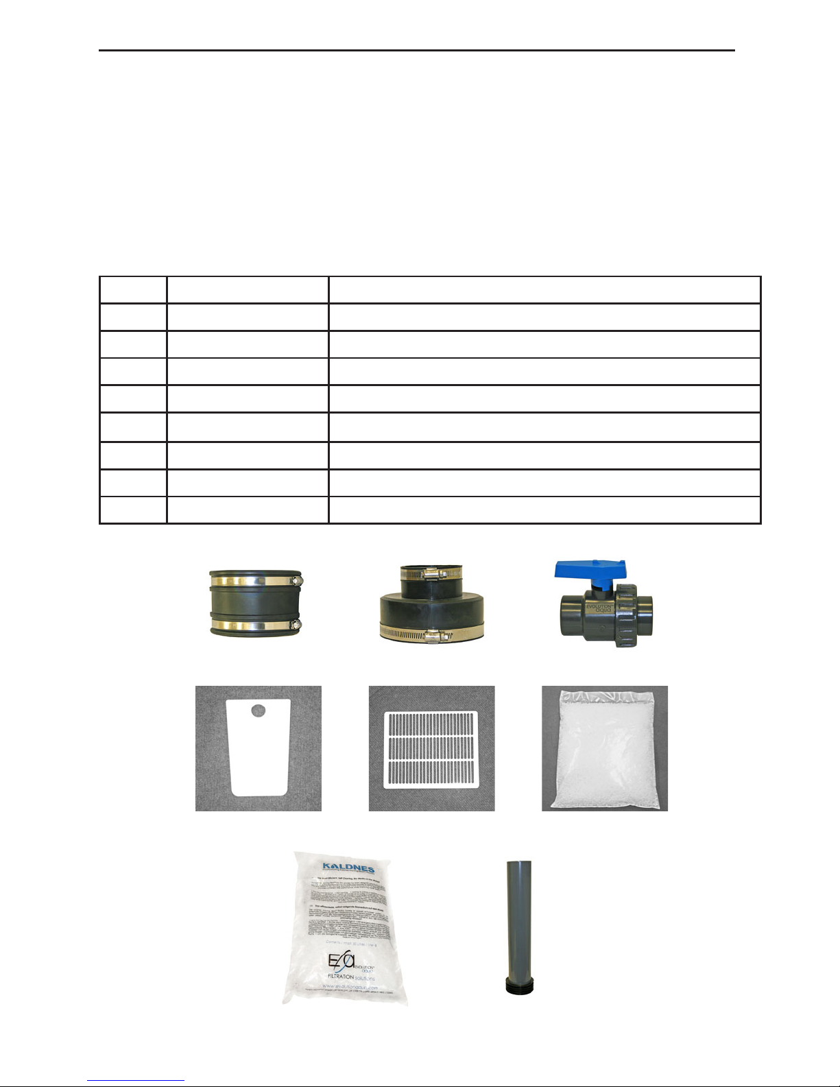
Your Nexus Pack should contain:
Figure Part No Description
1.1 NPC.125 4”-4” (110-125mm) rubber boot
1.2 NAC.1004 4”-2” (122-68mm) rubber boot
1.3 825-50-50 1.5”(50mm) single union ball valve
1.4 1200-400/100-400 inlet slide plate (200/300)
1.5 5000-707 safety outlet grill
1.6 MEDIA30L / 45L bag Kaldnes K1 for Eazy (30L - 200/ 45L - 300)
1.7 MEDIA50L 50L bag Kaldnes K1 (1x Nexus 200, 2x for Nexus 300)
1.8 5000-329 Eazy isolation pipe
Fig 1.4
Fig 1.3Fig 1.2.Fig 1.1
Fig 1.6
Fig 1.8
Fig 1.5
Fig 1.7
Page 4

EXPLANATION
-2-
Basic Operation Nexus:
The Nexus lter is simple yet innovative. Water enters the Nexus via inlet (A) Fig 2
into the inner chamber (B) which works as a basic vortex allowing larger solids to
settle out. The water then passes through the Eazy (C) where the ner particles
are removed and the rst step
in biological treatment takes
place. From the Eazy the water
passes into the outer chamber
(D) where the remainder
of the biological treatment
takes place using the Kaldnes
Moving Bed Process.
The water then passes
through the grill into the
Outlet Chamber (E), where
it is returned to the pond
through the outlet (F). All
waste is discharged through
the waste valves (G). The Eazy
is cleaned by diverting the air
from the Outside chamber to
the Eazy using the valve (H).
Basic Operation Eazy :
The Eazy™ is a stainless steel vessel containing a set volume of static K1 media
(30L for Nexus 200, 45L for Nexus 300) which is located within the centre chamber
of the Nexus. After water enters the Nexus it rotates around the Eazy in the
centre chamber with a downward motion allowing the larger solids to settle
to the bottom of the chamber before passing through the slots of the Eazy into
the static K1 media. After passing through these slots the water ows upwards
through the K1 media where mechanical ltration takes place as small particles
are caught within the K1 media. The water then ows over the slots in the centre
column and into the outer chamber.
Basic Operation Outer Chamber:
The outer chamber of the Nexus contains the Kaldnes Moving Bed Process this
is where the nal stage of biological treatment occurs. Biological breakdown
occurs through different strains of bacteria living on the K1 media. These bacteria
consume Ammonia and Nitrite transforming them into harmless Nitrate. The
amount of Ammonia and Nitrite produced in the pond is dependant on feed
rates and the type of food. For higher feed rates additional K1 media should be
added into the outer chamber (250g/day of average protein content food will
be broken down by 50L of K1).
Fig 2
Page 5

INSTALLATION
-3-
Nexus Setup
This section should be thoroughly read before proceeding with any installation.
Checks to do BEFORE Installation
Check the jubilee clips on the rubber boots are tightened to prevent leaks
Check that the collars on the waste valves are tight
(This is required as some loosening may have occured in transit)
Preparation
Important:
A solid and level base/ground is required. It should be a minimum of 1.2m x
1.0m, to allow easy access to valves and for maintenance purposes. The Nexus
lter needs to be equally supported, this is to prevent possible distortion when it
is full of water. The best option for this would be a level 100 mm thick concrete
plinth. Although decking, paving slabs or well packed gravel would be sufcient
as long as the Nexus sits level and is not allowed to deect under the weight of
the water.
The Airpump should always be situated well above water level to prevent water
siphoning back into the pump should a power failure occur.
Installation Equipment required
Pond Pump, with a maximum actual (taking into account the head loss) 1.
owrate no more than your Nexus model allows see Appendix A on page
12 for specs.
Air Pump to power the Kaldnes K1 Moving Bed, see Appendix A on page 12 2.
for specication of pump size.
Length of hose or braided pipe (10 mm inner diameter) to connect the air 3.
pump to the Nexus
A valve should be tted before and after the Nexus so that the Nexus can be 4.
isolated if required. On Gravity Fed systems this should be a 4 inch (110mm)
ball valve located on the inlet side of the Nexus close to your lter house
wall.
A reducer to connect the 2 inch Nexus rubber boot to your pump.5.
It is highly recommended that a suitably sized UV unit is installed with the 6.
Nexus for removal of single celled algae. UV systems are always installed
after the pump, so on Gravity fed Nexus the UV is after the Nexus and prior
to the Nexus on Pump fed installations.
It is also highly recommended that you t an overow pipe/drain to your 7.
pond.
The Nexus can be installed in either of two ways Gravity Fed or Pump Fed, the
Nexus is shipped complete to be set up in either format with all the necessary
components. The following sections explain how this is done.
Page 6

GRAVITY FED INSTALLATION
-4-
A gravity fed system is where the water level in the Nexus is at the same height as
the water level in the pond, therefore the top of the Nexus should approximately
be at the same height as the top of the pond as shown in Figure 3.
The water on a Gravity fed systems should be fed from a appropriately placed
bottom drain through at least a 4 inch (110mm) pipe with as short a length and
fewer bends as possible (For optimum ow swept bends should be used). At the
end of the bottom drain line before entering the Nexus a valve is required so
that the line can be shut and the Nexus isolated.
For long bottom drains it is recommended that a purge valve line is installed to
remove solids that may settle in your bottom drain line. This should discharge
straight to waste (if possible) or into a suitably sized sump.
It is very important that when laying the bottom drain line that there is no section
where the pipework rises then falls as airlocks can form in this area which will
block ow. Figure 4 below describes what should and shouldn’t be done.
Pipework should be level until reaching the lterhouse where it should ideally go
through a swept bend 90 into the Nexus inlet.
Fig 3
From Pond
To Nexus
From Pond
To Nexus
Fig 4
Page 7

GRAVITY FED INSTALLATION
-5-
* Useful Tip on Getting your water Level right
Getting the water level right in your Nexus is important as if this level is too low
it will affect the ow rate from
your bottom drain as well as the
efciency of your Eazy both in
cleaning and blocking rate. If
the level is too high, you may get
Kaldnes overowing between
chambers. The ideal level is located
just under the top lip of the Nexus
as shown in Figure 5.
The way to measure how high your
Nexus base should be is to measure
the height between your pond
water level and lter bay using a
spirit level or a laser level. And with
a tape measure calculate the appropriate base level.
Gravity Fed Installation Steps
Attach the 4”-4” Boot (Fig 1.1) to the Nexus Inlet (A) then to the 4” bottom 1.
drain pipe by tightening both jubilee clips
Attach the 4”-2” Rubber Boot (Fig 1.2) to the Nexus Outlet (F)2.
Connect the 1.5” Single Union Ball Valve (Fig 1.3) to the 4”-2” Rubber Boot 3.
(Fig 1.2) with the union side facing down towards the pump (depending
on your arrangement you may require an elbow between the boot and
valve)
Connect your water pump to the Single Union Ball Valve (Fig 1.3) on the 4.
union side
Place the 50L K1 media bag into the outside chamber (D) of the Nexus (300 5.
x 2)
Place the K1 bag marked either 30 or 45 into the Eazy basket (C)6.
Connect your air pump to the Nexus air inlet (H) located next to the water 7.
inlet using suitable hosing such as standard 12mm diameter garden hose
Connect your pump outlet to the remainder of your pipework including a 8.
UV steriliser.
Insert the safety exit gill (Fig 1.5) into the exit chamber (E)9.
Connect the waste valves (G) to your waste outlet (Described on Page7)10.
YOUR NEXUS IS NOW READY FOR USE
Pump fed installation is where the pump supplies water to the Nexus and water
returns by gravity through a 4” (110mm) pipe. Figure 6 shows an example of a
pump fed system.
Wa ter
Level
Page 8

PUMP FED INSTALLATION
-6-
It important that on the return line back to the pond there is no section of pipe
where the pipe rises then falls as airlocks will form in this section stopping ow an
example of this is shown in Figure 4.
When installing a pump fed Nexus
there is a maximum height difference
that the Nexus base can be below
the pond water level also shown in
the Fig 6. This height is dependant
on the distance between the Nexus
and the return point to the pond,
the table below shows the maximum
heights and distances when using 4” (110mm) pipe.
Important: Essential Action
For Pump fed units it is important that you get the height of the outlet standpipe
correct. The height of this standpipe is very important as it controls the height that
the outer biological chamber of
the Nexus runs at. For a standard
Nexus installation you need to
cut a length of your 4” (110mm)
return pipe: 21” (535mm) for a 200
and 23.2” (590mm) for a 300. This
needs to be inserted into the exit
chamber (E) through the outlet
(F) and then secured using the
4”-4” (110mm) (Fig 1.1) rubber
boot leaving 2” (50mm) below as
shown in Fig 7. 2” (50mm) of pipe
below the boot will allow you to
connect any tting onto your
Nexus such as a valve, elbow or
straight connector. To check that
you have the height of the outlet
pipe correct you can measure
from the top of the standpipe to
Fig 6
Max distance (H) below water
level of Nexus base
Nexus 200 Nexus 300
Next to Pond 350mm 14” 500mm 20”
Within 5m 100mm 4” 250mm 10”
Over 5m At or above water level
Fig 7
Fig 8
Page 9

PUMP FED INSTALLATION
-7-
the top of the Nexus plastic lip as shown in Fig 8. For the 200 the distance needs
to be 110mm and 120mm for the 300.
Pump Fed Installation Steps:
Insert the Exit pipe into the Nexus Outlet (F) and secure using the 4”-4” Boot 1.
(Fig 1.1) as described in previous section page 6.
Connect the 4”- 2” Boot (Fig 1.2) to the Nexus Inlet (A).2.
Connect the Single Union Ball (Fig. 1.3) to the 4”-2” Boot (Fig 1.2) with the 3.
union side towards the pump.
Connect the hose/pipework from your pump to the Single union ball valve 4.
(Fig 1.3) ( If using exi-hose you will require a hose tail).
Connect your 4” pipework from the Exit pipe back to the Pond.5.
Place the 50L K1 media bag into the outside chamber of the Nexus (x2 for 6.
300).
Place the K1 bag marked either 30 or 45 into the Eazy basket (C).7.
Connect your air pump to the Nexus air inlet (H) located next to the water 8.
inlet using suitable hosing such as standard 12 mm diameter garden hose.
Connect the waste valves (G) to your waste outlet (Described Below).9.
Waste Pipe Connection
The waste valves are where the waste from your Nexus is discharged when
cleaning and prior to draining. The 1.5” (50 mm) valve is for the Inner Chamber
(B) and is used for when cleaning the Eazy, while the ¾” (20 mm) valve is for
draining the outer chamber (D)(only when and if required).
Both of these valves can be connected using a waste pipe kit (optional extra) as
shown in Figs 9.1-3 or can just be discharged individually. If the Nexus is located
below your drain height the waste can be either discharged into a sump where
a submersible pump can be used to pump the waste away or an inline pump
can be connected to the wasteline where it can pump directly to waste.
Fig 9.1
As Installed
Fig 9.2
Exit to Left
Fig 9.3
Exit to Right
Page 10

Once your Nexus is installed and plumbed in as described above, you are ready
to ll the Nexus and begin treating your pond water.
To ll your Nexus rst you need to open all your valves before and after the
Nexus. With a pump fed unit you then need to switch on your pump making sure
that the owrate is not too fast (refer to the section below). A gravity fed system
will just ll until it reaches water level.
Once the Nexus is full, you will notice that
the Kaldnes K1 media is positively buoyant
and oating on the water surface. In a
pond containing sh the media can attain
neutral buoyancy in 2-3 hours while in a
newly lled and stocked pond it can take
up to a week for this to occur. For people
installing a Nexus on an existing pond, the
Kaldnes K1 media can be primed before
use, by soaking it in pond water prior to
installation.
When your Nexus is full it is time to turn on your airpump to circulate the media
making sure the valve to the outer chamber (bottom valve) is open and the
valve to the Eazy (top valve) is closed, as per gure 10. Once your media
has achieved neutral buoyancy it will move and circulate around the outer
chamber as shown in Fig 11.
Importance of Flowrate
The owrate through your Nexus affects
how your Nexus runs in two different
ways. You will visually notice straight
away that the levels in both the inner
and outer chamber will run at different
heights depending on the owrate.
Because of this the owrate also helps
determine the interval between when
the Eazy needs to be cleaned though
this is mainly dependant on the type of
food you are feeding and the amount
of algae in your pond.
The owrate of your pump can be adjusted by slightly opening or closing the
valve after your pump. For Gravity Fed systems if the level in the outside chamber
is dropping (when your eazy is clean) your owrate is too fast and needs to
be slowed down. While with Pump fed systems, if your inner chamber level is
rising quickly (when easy is clean) and overowing into the outer chamber your
owrate is too fast.
GETTING STARTED
-8-
Fig 10
Fig 11
Page 11

CLEANING
-9-
Gravity Fed
With a gravity setup, the level in the outer chamber (D) will lower as the Eazy
becomes dirty and the K1 in the Eazy will rise. By looking into the inner stainless
steel column on the Eazy you can see what height the water is passing through
the Eazy into the outer chamber. When the water level becomes low on the
steel slots and high turbulence is seen the Eazy should be cleaned.
Stop the circulation pump.1.
Wait a short period of time to allow the water levels within the Nexus to 2.
stabilise.
Close off the feed to the biological chamber by inserting the isolation pipe 3.
into the centre of the “Eazy”, ensuring that the rubber ange engages within
the Nexus centre spigot Fig 12.
Close the inlet to the Nexus by inserting inlet slide-plate (Fig1.4) supplied with 4.
your Nexus. Your Eazy is now isolated from the rest of the system.
Now clean the Eazy as in described in “Cleaning the Eazy” on page 10.5.
Remove the Nexus inlet slide-plate allowing the nexus to rell.6.
Remove the Isolation pipe.7.
Restart your pump.8.
Pump Fed
With a pump fed setup the level in the inner chamber (B) rises when the Eazy
becomes more blocked, the Eazy has to be cleaned before this level gets too
high and overows into the outer chamber (D).
Reduce ow to Nexus by closing single union ball valve most of the way, 1.
leaving valve partially open.
Close off the feed to the biological chamber by inserting the Isolation pipe 2.
into the centre of the “Eazy”, ensuring that the rubber ange engages within
the Nexus centre column Fig 12.
Watch the level in the inner chamber rise until the water level reaches the 3.
1” (25mm) below the top of the Eazy outer drum, then close the single union
ball valve. It is essential that this water level is maintained to allow efcient
cleaning.
Switch off the pond pump.4.
Now clean the Eazy as in described in “Cleaning the Eazy”5.
Open the single union ball valve and start pump.6.
Once the water level in inner chamber (B) reaches the level in the outer 7.
chamber (D) remove the isolation pipe.
Page 12

Once you have your Eazy ready to be cleaned as described in the previous
section you are ready to clean your Eazy as explained below.
Open the top air valve to the Eazy then close the bottom valve to the outer 1.
chamber as shown in Fig 13. The Kaldnes in the “Eazy” shall start to aerate
within a few minutes as shown in Fig 14.
After the “Eazy” has been aerating for a minimum of three minutes, open the 2.
1.5” (50mm) waste valve (G) to drain waste from the inner Nexus chamber.
Once the central chamber has drained it is recommended you give a quick 3.
clean to the inner chamber and outer stainless steel of the Eazy with a hose
then close the 1.5” waste valve.
Gravity Fed - Remove inlet slide-plate (Gravity Fed) until level stabilises then 4.
replace slide plate.
Pump Fed - Open single union ball valve and start pump allowing inner 5.
chamber to rell until the water cleaning level is reached as in Fig 14. Then
close valve and switch of pump.
The Eazy should now be aerating again. After the Eazy has boiled for another 6.
few minutes open the waste valve again.
Repeat steps 1-6 until the water after aerating is fairly clean7.
Close the airvalve to the Eazy and re-open the valve to the outer chamber8.
Go back to previous instruction for pump or gravity fed.9.
CLEANING THE EAZY
-10-
Figures 12-14
Starting Clockwise
from Above
Page 13

The Kaldnes Moving Bed™ process, has
been scientically tried and tested in sh
farming and waste treatment for over 10
years. Developed by Professor Halvard
Ødergard at Trondheim University of Science
and Technology the Kaldnes Moving Bed™ bio lm process has been designed
specically to create the most effective environment for the nitrication process
to take place. The media is engineered in a wheel shape and is slightly positively
buoyant, allowing a small amount of water ow created by adding air to the
process) to circulate the media throughout the vessel.
Oxygen and food (ammonia and nitrite) gives the bacteria the means to grow,
whilst the Kaldnes media provides maximum surface area for the bacteria to
colonise and produce bio lm. It is this process, which removes harmful ammonia
and nitrite from the water. As the Kaldnes media chaotically circulates within
the bio tank, it causes old dead bacteria/bio lm on the outside, to be removed
making space for new younger heavier feeding bacteria/bio lm to colonise.
Within the wheel, is a protected surface, which enables colonies of bacteria
to naturally follow their life cycle, maturing and dying, in turn fuelling the latter
stages of nitrication conversion process. It also assists in the breakdown of
any small particles passing through from the mechanical stage. Therefore, the
Kaldnes media maintains both a young biolm & a maturing bio lm providing a
more consistent lter performance, whilst improving water quality, encouraging
healthier Koi and aiding in reducing green water and blanket weed. Due
to chaotic movement of Kaldnes K1 media, the process is self-cleaning and
requires no maintenance. This allows the lter to reach optimum effectiveness
without the disturbance of periodic maintenance, avoiding unnecessary loss
of bacteria within the lter preventing high levels of ammonia and nitrite within
the water. The other major benet of Kaldnes K1 media is the huge ‘active’
surface area available for the bacteria to grow on compared to other types of
media. This feature allows for smaller lter design, e.g. the Nexus, whilst providing
increased biological efciency.
KALDNES K1 MEDIA
-11-
Mature media
at high feeding loads
Mature media
at low feeding loads
Virgin media
Page 14

Appendix A
-12-
Specication Nexus Eazy 200 Nexus Eazy 300
10,000 Litres/hr 13,000 Litres/hr
Max Flow Rate 2,200 UK Gallons/hr 2,859 UK Gallons/hr
2,640 US Gallons/hr 3.431 US Gallons/hr
Kaldnes Media 50 ltrs bio/ 30 ltrs Eazy 100 ltrs bio/ 45 ltrs Eazy
Max Capacity 150 ltrs bio / 30 ltrs Eazy 300 ltrs bio / 45 ltrs Eazy
18,000 Litres 34,000 Litres
Max Pondsize 4,000 UK Gallons 7,500 UK Gallons
4,800 US Gallons 9,000 US Gallons
Rec. Airpump Airpump 70 -75 Airpump 95+
Volume lter Nexus Eazy 200 Nexus Eazy 300
105 Litres 205 Litres
Chamber B 23 UK Gallons 45 UK Gallons
28 US Gallons 54 US Gallons
405 Litres 635 Litres
Chamber D 89 UK gallons 139 UK Gallons
107 US Gallons 168 US Gallons
510 Litres 840 Litres
Total volume 112 UK Gallons 185 UK Gallons
135 US Gallons 222 US Gallons
Total K1 Media in Chamber D Recommended Airpump
50 - 75 Litres Airpump 70 - 75
75 - 100 Litres Airpump 95
100 - 150 Litres Airpump 130
150 + Litres Airpump 150
Page 15

Appendix B
-13-
225
315
850
270
W a ter
Level
1025
480
380
425
480
950
1010
785
735
1110
D 960
W a ter
Level
370
1260
315
1320
D 1110
370
1430
320
Page 16

Page 17

Page 18

Page 19

Page 20

 Loading...