

Page 1

AIR SOURCE WATER HEAT PUMP
HIGH TEMPERATURE UNITS
Installation & Instruction Manual
Polaris MT 70 Manual
Page 2

1 Preface
2 Safety Precaution
2.1
2.2
2.3 Warning
2.4 Caution
3 Specification
3.1
3.2
4
5 Installation
5.1
5.2
5.3
5.4
5.6
5.7
5.8
6.Usage
6.1 Function of wire controller
6.2 Usage of wire controller
7.1 Malfunction table
8.Appendix
8.1 Connection of PCB illustration
8.3 Appendix
Marking Description
Icon Description
Performance Parameter List
Outline Dimensional Drawing
Unit Function Description
Installation Space
Installation Schematic Diagram
Model Selection
Selection of the Installation Position
5.5 Installation Mode
Water Pipe Connection
Electrical Wiring
Moving
5.9Trial Operation
7.Maintenance and inspection
8.2 Caution & Warning
CONTENT
1
2
2
2
3
4
5
5
6
7
8
8
8
9
9
10
11
11
13
13
15
15
16
15
27
28
28
30
31
1.Preface
Page 3

1
This manual includes all the necessary information about installation, debugging,
discharging and maintenance. Please read this manual carefully before you open or
maintain the unit.
Read these operating and installation instructions carefully and keep them safe. Should
the equipment change hands, pass these instructions to the subsequent owner. Pass them
to the trained contractors for servicing purposes. Positioning, installation and
commissioning must be carried out by trained personnel working in accordance with these
operating and installation instructions.
When the product is delivered to the users, please check whether there is any damage on
the unit during transportation; If any please talk with the forwarder or the contractor.
If the heat pump unit can just be installed a while latter, please keep it free from damage,
rust or abrasion by following methods.
1. all the access like the water connections must be sealed correctly;
2. the unit must be free from sunshine, and placed under 45℃;
3. the unit must be free from heavy dust to avoid dirty on the evaporator;
4. the unit must be placed free from chaos to avoid accident;
The pictures and drawings in this manual are for your information only. The manufacturer
has the right to chance or improve the product when it is needed, without prior notification
to the users of this device.
1.Preface
It is vital that the below instructions are adhered to at all times to keep the warranty.
—The unit can only be opened or repaired by qualified installer or an authorised dealer.
—Maintenance and operation must be carried out according to the recommended time and
frequency, as stated in this manual.
Page 4

2
2.Safety Precaution
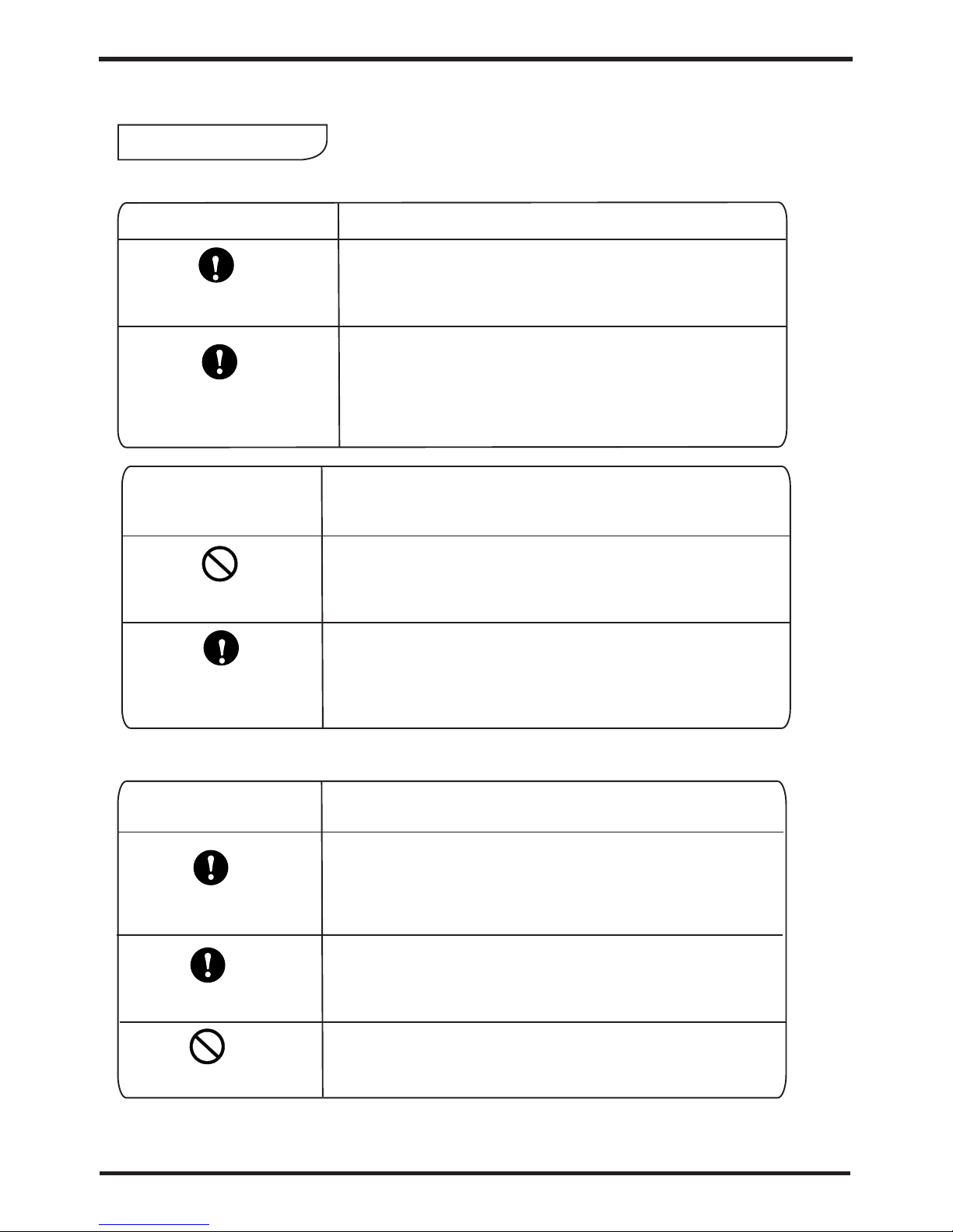
2.1 Marking Description
Marking
Description
Mis-operation (misuse) may cause death or serious injury.
Mis-operation (misuse) may cause personal harm or
material damage.
Warning
Caution
2.2 Icon Description
It indicates prohibition. Detailed prohibitions are represented
by graphics or words in or near the icon.
It indicates mandatory (execution).
Detailed mandatory items are represented by graphics or
words in or near the icon.
It indicates caution (including warning).
Detailed cautions are represented by graphics or words in or
near the icon.
To prevent the user himself or others from personal and property damage and ensure correct and
safe use of the unit, please read the important contents described in this Manual carefully. Read the text
with full understanding of the following contents (marking and icon), and follow the following precautions.
Marking
Description
1. The above-mentioned harm in the Description refers to the harm that does not
require hospitalization or long-term treatment, and refers to injuries, burns and electric
shock in general.
2. The above-mentioned material damage refers to losses of property and materials.
2.Safety Precaution
Moving and Repair
Entrust the professionals
for installan
Page 5
3
2.Safety Precaution
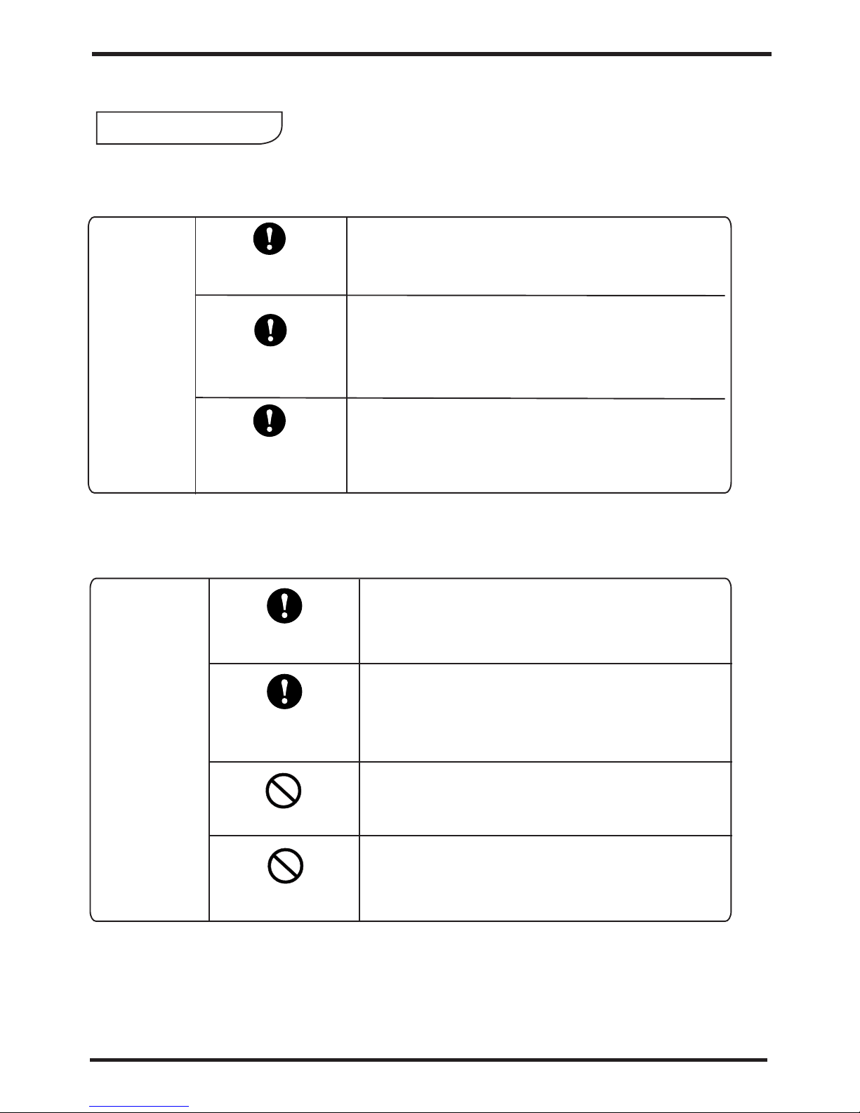
Please entrust the professionals for installation.
The installation by others may cause installation
imperfections, resulting in water leakage, electric
shock or fire.
Verify whether the grounding is proper.
Improper grounding may cause electric shock.
Installation Warning
Verify the ground wire
2.3 Warning
Description
Use Warning
Description
Prohibit
Cut off the
manual power
Do not put your fingers, sticks and other objects into
the air outlet or the air inlet.
Because the wind wheel operates at high speed inside,
it may cause injury.
When abnormal conditions (burning smell) occur,
immediately cut off the manual power switch to stop
running and contact the dealer.
Continuing abnormal conditions may cause electric
shock or fire.
Moving and Repair
Warning
Entrust
Prohibit
Entrust
If it is necessary to move and re-install the air
conditioning, entrust the dealer or professionals for
implementation.
Improper installation may cause electric shock, fire,
injury, water leakage and other accidents.
It is prohibited to repair the unit by the user himself, otherwise
electrical shock or fire may be occur.
For repair, entrust the dealer or professionals.
Improper repair may cause fire, electrical shock, injury,
water leakage and other accidents.
Entrust the professionals
for installan
Description
Page 6
4
2.Safety Precautions
Use
precautions
Check the
installation bench
Cut off the manual
power switch
Prohibit
Prohibit
For long-term use, check whether the installation
bench is firm and intact.
If installation bench is damaged or weak, the
outdoor unit may fall, causing casualties.
Stop the operation during cleaning, and cut off the
manual power switch.
If the machine does not stop operation, it may
cause injury due to the wind wheel running at a
high speed inside.
Use the appropriate fuse.
If copper or iron wires are used, it may cause
malfunction or fire.
Do not spray the combustible spray directly to
the outdoor unit; otherwise, this may easily
Installation
precaution
Do not install it in a place where flammable gas leak
easily occurs.
Once the flammable gas leaks and stays around the
outdoor unit, this may cause a fire.
Verify whether the leakage protection switch has
been installed.
If the leakage protection switch is not installed, this
may cause electric shock or fire.
Verify whether the installation base is solid.
If the base is not solid, the outdoor unit may fall and
then result in accidents.
2.4 Caution
Verify the
installation site
Verify the
fixing means
Verify the leakage
protection switch
3.Specification
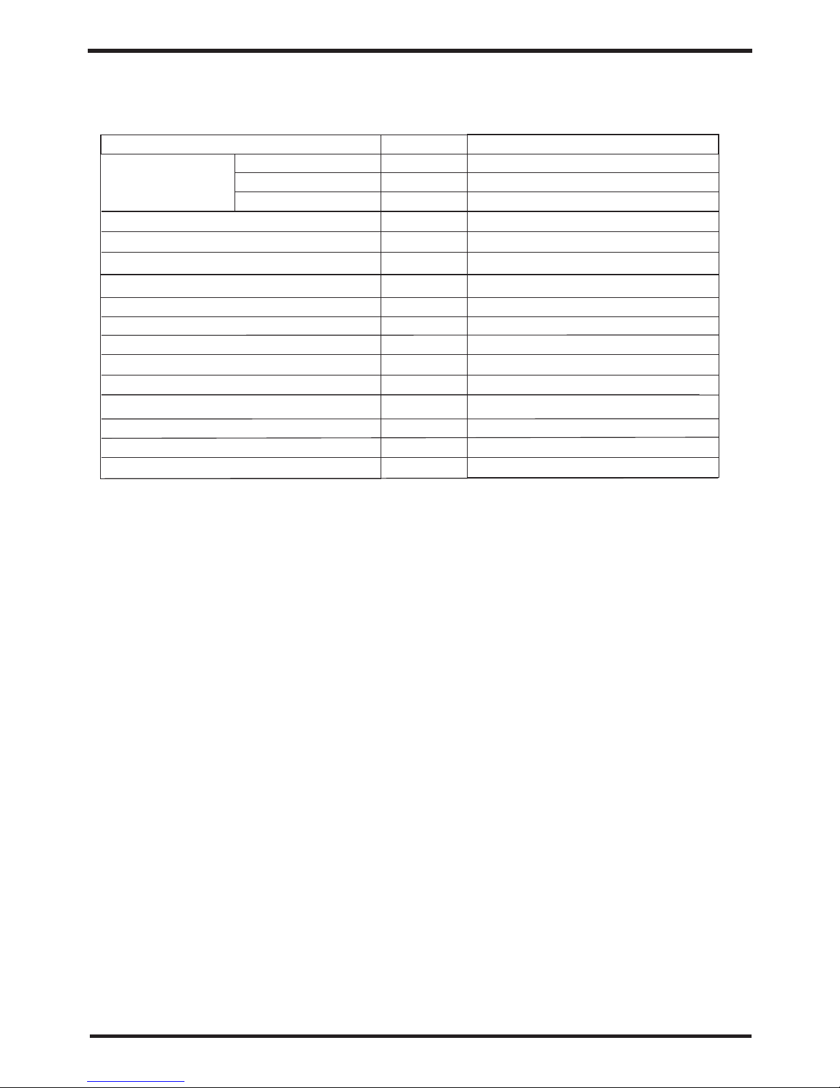
Testing condition: ambient temperature DB/WB 20 C/15 C;
outlet water 65 C, inlet water (return) 55 C;
Recyc led-heatin g
3.1Performance Parameter List
Page 7
5
3.Specification
o o
Testing condition: ambient temperature DB/WB 20 C/15 C;
o o
outlet water 65 C, inlet water (return) 55 C;
117.0
37.5
70.0
AL LH T11 70R13 4
kW
kW
A
Heati ng Output
Power I nput
Runni ng Current
Unit Mo del
Recyc led-heatin g
2
2000×2
920
75
380V/ 3N~/50Hz
(Subj ect to data on the p ackage)
Namep late
W
RPM
dB(A)
mm
mm
kg
kg
Power S upply
Scrol l
Compr essor Typ e
4
Compr essor Quanti ty
Fan Qua ntity
Fan pow er input
Fan spe ed
Noise
Water pipe connection
Unit di mension (L/W /H)
Packa ge size(L/W/ H)
Net Weight
Gross w eight
DN80
Refri gerant Type
R134a
Packa ge
(Subject to drawings o f the h eat p ump )
3.1Performance Parameter List
Page 8
6
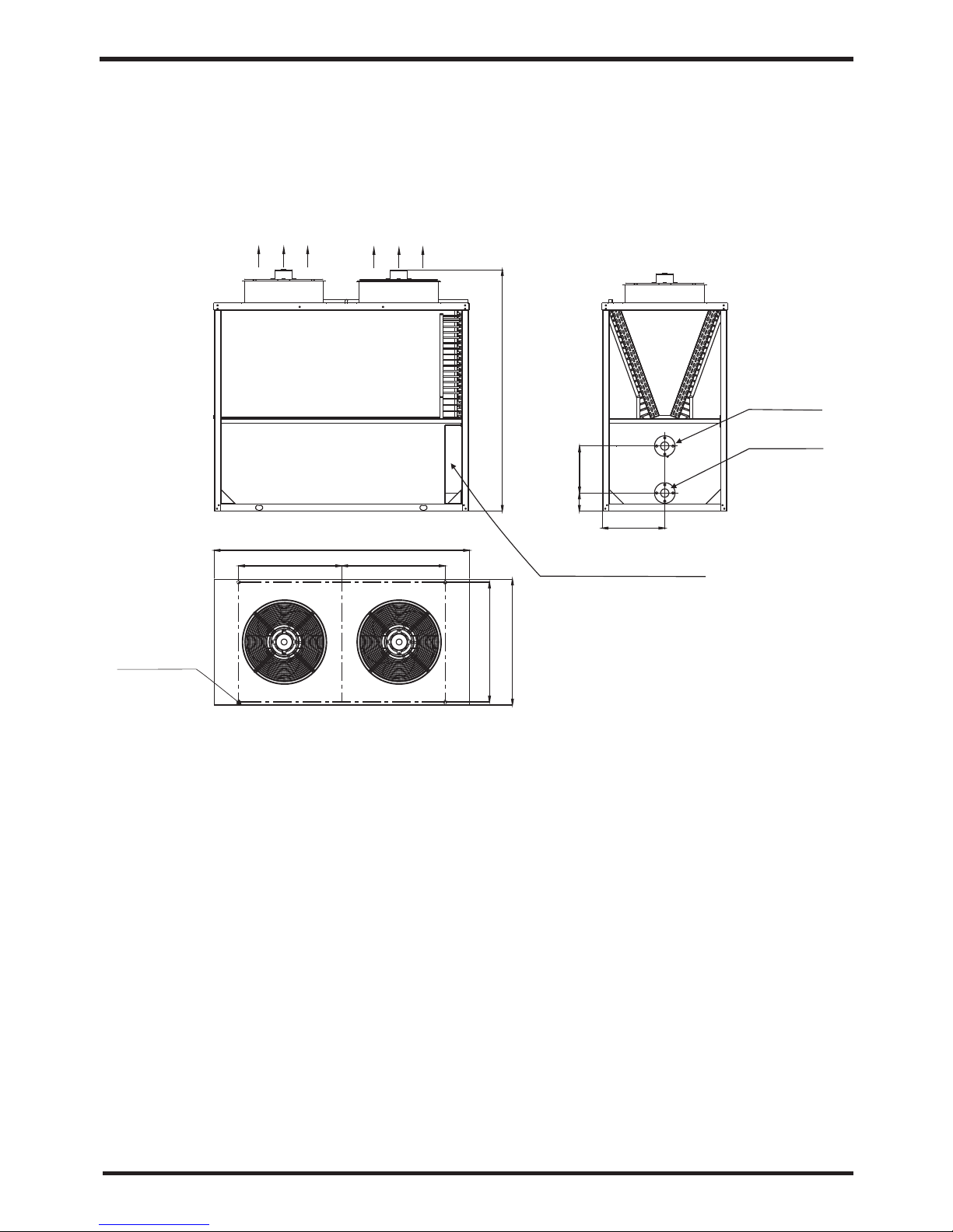
3.2
Outline Dimensional Drawing
3.Specification
Air-out di rec tio n
Installa tio n
Bottom Outlet
Water outlet
DN80 flang e
Electrical co ntr ol box
4-Φ16
2030
2180
900 900
1080
1020
400
175
530
Water inlet
DN80 flang e
Models: AL LHT 1170R13 4
4.Unit Function Description
The unit absorb energy from outside and release the heat according to the heat
exchanger, if the environment temperature is low, the heating capacity will be
attenuation.
Heating capacity
3 minutes protection
When the unit stop, if you restart the unit or turn on the manual switch, the unit will not run
in 3 minutes, it's the protection for the compressor.
If the environment temperature is too high, the unit will stop running to protect the
compressor.
Defrosting
Under the heating mode, the unit will defrost automatic to make sure the heating
efficiency (it will last 2-10 minutes).
Working condition
In order to use the unit correctly, please run the unit at environment temperature -7℃-43.
The unit includes sophisticated electronic devices, prohibited to use water from lake,
untreated river water and groundwater!
Power off
If the power supply is off, the unit will stop running. If the running unit is disturbed by
lightning, car radio, power grid fluctuations please cut off the manual power switch , and
then power on, press the on / off button.
leakage current protection
There is a leakage current action protection comes with the power supply wire.
Electric heating protection
When the water temperature reach 94℃, electric heating fuse will melt off (can not be
restored).
Hight pressure protection
Page 9

7
4.Unit Function Description
The unit absorb energy from outside and release the heat according to the heat
exchanger, if the environment temperature is low, the heating capacity will be
attenuation.
Heating capacity
3 minutes protection
When the unit stop, if you restart the unit or turn on the manual switch, the unit will not run
in 3 minutes, it's the protection for the compressor.
If the environment temperature is too high, the unit will stop running to protect the
compressor.
Defrosting
Under the heating mode, the unit will defrost automatic to make sure the heating
efficiency (it will last 2-10 minutes).
Working condition
In order to use the unit correctly, please run the unit at environment temperature -7℃-43.
The unit includes sophisticated electronic devices, prohibited to use water from lake,
untreated river water and groundwater!
Power off
If the power supply is off, the unit will stop running. If the running unit is disturbed by
lightning, car radio, power grid fluctuations please cut off the manual power switch , and
then power on, press the on / off button.
leakage current protection
There is a leakage current action protection comes with the power supply wire.
Electric heating protection
When the water temperature reach 94℃, electric heating fuse will melt off (can not be
restored).
Hight pressure protection
Page 10
8
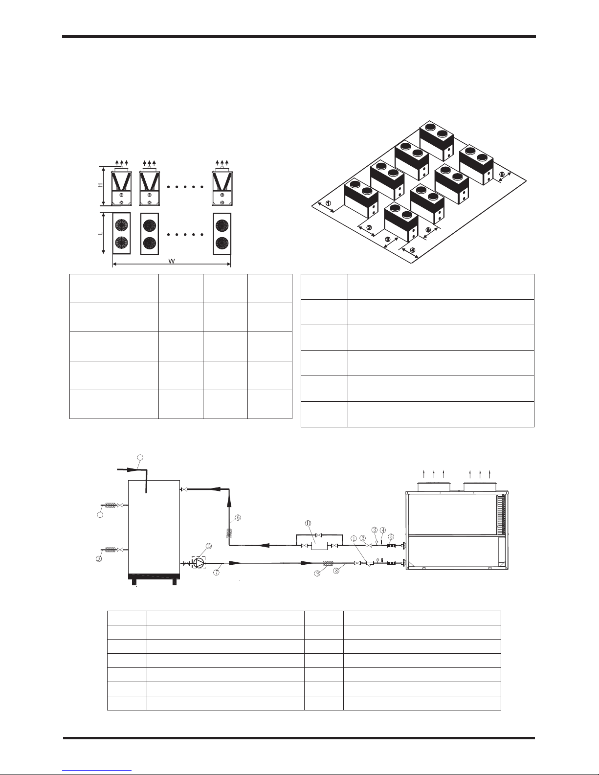
5.Installation
5.2 Installation Schematic Diagram
1
3
5
7
Y-type filter
Thermometer (0-100℃)
Connecting hose
Hot Water Circulating Pipe
2
4
6
8
Shut-off valve
Pressure gauge (0-1.0MPa)
Hot Water Circulating Pipe
Water supply pipes
Water Tank
Air-out di r
e
cti
on
1
3
8
Thermal insulation
Hot Water Supply Pipe
Electric auxiliary heater
Water pump
Hot Water Return Pipe
9
10
11
12
13
5.1Installation Space
2180
2180
2180
2180
3160
5240
7320
9400
2030
2030
2030
2030
Dimensions
Outline Dimensional
Drawing - Parallel Units
Schematic Diagram of Unit
Installation Position
Air-out direction
Parallel Mode
Double-
connected unit
Tripartite-
connected
Quadruple-
connected
Quintuplicate-
connected unit
L(mm)
L(mm) L(mm)
1
2
3
4
5
6
Maintenance space above 1800mm
Unit spacing above 1500mm
Maintenance space above 1500mm
Maintenance space above 1500mm
Maintenance space above 1800mm
Maintenance space above 1000mm
5.Installation
5.3 Model Selection
(1)Make comprehensive consideration of the required refrigerating (heating) capacity per unit
area according to climatic conditions, building use and heat preservation;
(2)Calculate the total load according to the unit load and the total area;
(3)Select the appropriate unit based on the total load and the application scope of the unit.
(4)Application occasions:
5.4Selection of the Installation Position
Page 11

9
5.Installation
5.3 Model Selection
(1)Make comprehensive consideration of the required refrigerating (heating) capacity per unit
area according to climatic conditions, building use and heat preservation;
(2)Calculate the total load according to the unit load and the total area;
(3)Select the appropriate unit based on the total load and the application scope of the unit.
(4)Application occasions:
5.4Selection of the Installation Position
The unit can be installed on balconies, roofs, floors, or any other places easy to install
and reliable for load-bearing;
Air circulated places;
Places without thermal radiation or other heat sources;
Install a snow shed in winter;
Places without obstruction near the suction inlet or the exhaust outlet;
Places where the exhaust outlet is free from heavy winds;
Drainage channels shall be equipped around the machine to drain the condensed
water;
Enough space should be remained around the machine.
Page 12

10
5.Installation
5.5 Installation Mode
The unit is directly secured to the cement base with the expansion bolts.
Use channel steel to make the installation base, place shockproof rubber pads on
the ground or the roof, and ensure that the unit is placed levelly.
Air-out direction
1500mm
Figure 1 Installation Schematic Diagram of Snow Shed
To ensure the proper functioning of the unit in cold
areas in winter, the snow shed must be installed
during the engineering installation.
Caution
5.6 Water Pipe Connection
5.7 Electrical Wiring
5.Installation
Page 13

5.6 Water Pipe Connection
Note the following items during connection of water inlet and outlet pipes:
`
Minimize the resistance of the water pipe outside the unit.
The entire piping system should be clean and free of dirt and rust to prevent pipe
clogging. Test for leakages after the pipes are installed to ensure that the entire
piping system is free of leakage, and then coat with the insulating layer.
The pipeline should be conducted with a pressure test separately, rather than
together with the air conditioning main engine.
An expansion water tank should be installed at the highest point of the water
distribution pipeline, where the highest point of the water level in the expansion water
tank is at least 0.5 meters higher than the water distribution pipe.
Flexible joints should be used between the unit interface and the field piping to
reduce the vibration spread to both buildings and equipment. Both the pipe and the
fittings must be independently supported, but should not be supported by the unit.
The thermometer and the pressure gauge should be installed at the water inlet and
outlet pipes of the unit to facilitate the inspection during operation.
Drainage interfaces should be installed at all low positions of the water system (the
unit has a drain port to facilitate drainage; interfaces will be added in other positions
on site) so that the water in the system will be completely drained if it is not used in
winter; automatic exhaust valves should be installed at all high positions so as to
facilitate to exhaust the air from the pipeline. No insulation is provided for both the
exhaust valves and the drain port for easy maintenance.
5.7 Electrical Wiring
Open the panel, and open the power line hole
Thread the power line through the hole and connect it to the power line terminal; and
the three-core control line of the remote controller shall be plugged with the three-core
signal line on the main board according to the wiring diagram.
For an external water pump, thread the power line of the water pump through the hole
and connect it to the water pump terminals.
If it is necessary to automatically control the auxiliary heat source, connect the control
output signal of the auxiliary heat source to the start switch of the auxiliary heat source.
If it is necessary to automatically control mode of the air conditioning terminal, connect
the mode control signal to the mode control switch on each indoor air conditioning
terminal.
5.Installation
11
Page 14

5.Installation
12
The master air switch
3
5
Wire controller
3
5 5
3
5
3
Wire controller
Wire controller
Wire controller
Power cablee
Model
(R,S,T,N, ground)
576S-V
Three-core signal line
2
3×0.5mm
Notes:
(1) The unit uses the three-phase power supply, and the cable specification in the
table above refers to the cable specification of each phase.
2
(1)Both the neutral line and the ground line use the 4mm cables, and both the
2
three-core signal line and the defrosting coordination line use the 0.5mm wires.
2 2
3×16 mm +2×2 5mm
5.8 Moving
5.Installation
5.9Trial Operation
5.9.1 Check prior to trial operation
Page 15

5.8 Moving
Warning
Do not touch the radiating fins behind the machine
by hand or with other objects!
Picture 2
When lifting is needed, use four sling wires
longer than 8m for lifting; during the lifting, use the
special lifting hole (hook) on the unit base. Pads
shall be provided at the contact between the
housing and the sling to prevent the damage to the
housing, as shown in Figure 2.
5.Installation
5.9Trial Operation
Check the piping system. Check whether the expansion water tank is filled with sufficient
water and whether the water supply for supplement is normal. Check whether the entire
piping system is full of water and whether the air is completely exhausted. Check
whether all valves in the system are opened. Check whether the pipelines are well
insulated.
Check the power distribution system. Check whether all power supplies have normal
voltage. Check whether screws of each power distribution part are locked, and whether
the power is distributed to the circuit according to the distribution wiring diagram. Check
whether the ground line is well connected.
Check the water chilling unit. Check whether all fastening screws and screws on the
mechanical parts of the unit are firm. Check whether there is any fault indication on the
operation lights on the outdoor control main board. Connect the pressure gauge to the
fluoridated inlet to detect the system pressure during operation.
5.9.1 Check prior to trial operation
13
Page 16

5.Installation
Turn on the machine with on the remote controller, and then immediately
check whether the water pump operates normally; if it is normal, observe the water
flow switch and the water pressure gauge of the water system: when the water flow
switch is in the ON state, the water pressure gauge shall show the water pressure of
about 0.2MPa.
After the water pump has operated for some time, the compressor will start. Judge
whether there is any abnormal sound in the unit during operation with the sense of
hearing; if there is any abnormal sound, immediately cut off the power and check the
unit; if there is no abnormal sound, continue the operation and then note whether
the pressure of the refrigerating system is normal.
Check whether the input power and the current of the unit are consistent with the
performance data list in the Manual; in case of incompliance, stop the unit for check.
Adjust the water supply valve in each room, so that the temperature of each room
meets the use requirements.
Observe whether the outlet water temperature is normal.
Parameters of the remote controller have been set in the factory, and the user shall
not adjust it without permission.
5.9.2 Trial Operation
14
6.Usage
6.1 Function of wire controller
Page 17

6.Usage
Welcome
V1.0
v1.0
Loading .. .. ..
Press the button to set the clock,
the timer on or timer off
Press this button to check button function
or system state.
Press this button to confirm current operation.
ON/OFF
Press this button to start up/shut off the unit,
cancel current operation or back to upper interface.
HELP
MODE
CLOCK
Button Name
Function
6.1 Function of wire controller
Press this key to select the upward option or increase
the parameter value.
Press this key to select the downward option or
decrease the parameter value.
Up
Down
15
Page 18

16
6.Usage
6.2.1 The way to use
You can use “ ”at any interface, it will show relevant button function of current interface.
You can press “ ”to exit the "help" interface.
For example:
Press “ ”at main interface, system will show all button function; Press “ ”at clock
interface, system will show“ ”、 “ ” 、“ ”and“ ”button function.
ON:Heating
Inle t temp .: 35.0℃
Outl et t emp.: 65. 0℃
1.
Pres si ng this key c ould turn
on/o ff the u nit, canc el t he
curr en t opera ti on or retur n
to the f or mer inter face.
Press“ ”
This s ym bol means
you ca n pa ge up
2.
Pres si ng this key c ould
sele ct t he upward o ption or
incr ea se the valu e of a
cert ai n paramet er.
3.
Pres si ng this key c ould
sele ct t he down wa rd option
or dec re ase the val ue of a
cert ai n paramet er.
4.
Pres si ng this key c ould
swit ch u nit mode, e nter
into t he n ext inter face or
save s et tings.
5.
Pres si ng this key c ould set
the sy st em time, or t ime for
regu la r shutd ow n or
rest ar t.
6.
Pres si ng this key c ould
chec k th e unit stat e or
show y ou t he key
func ti ons.
Mode
Both are OK when system show ON or OFF
ON:Eco.heating
Inle t te mp.: 25.0℃
Outl et t emp.: 25. 0℃
31/0 3/ 2011 09:10 THU.
Press“ ”
Press“ ”
Press“ ”
Press“ ”
Press“ ”
Press“ ”
6.2 Usage of wire controller
In the boot state
In the boot state
2016 /0 7/20 08:4 0 MON.
6.Usage
Press “ ”at clock interface, the screen shows as follow:
Both are OK when system shows ON or OFF
6.2.2 Starting up and shutting down
Page 19

17
6.Usage
Press “ ”at clock interface, the screen shows as follow:
Date: 20/07/2016
Time: 08:40
Week: Monday
Timer
Date format
Both are OK when system shows ON or OFF
Press“ ”
to enter
1. Up or down arrow
selects items
2. Clock key changes
status
3. On/off key exits
Press“ ”to show
relevant button function
Press“ ”
to exit
6.2.2 Starting up and shutting down
Press “ ”in the shutdown state for 1s to start up the system;
Press “ ”in the startup state for 1s to shut down the system.
For example:
Press“ ”
for 1s
Running state
MODE
(By actual state)
Month
Date
Time Week
ON:Heating
Inle t te mp.: 35.0℃
Outl et t emp.: 65. 0℃
OFF:Heating
Inle t te mp.: 25.0℃
Outl et t emp.: 25. 0℃
Year
ON:Heating
Inle t te mp.: 35.0℃
Outl et t emp.: 65. 0℃
In the shutdown state
In the startup state
2016 /0 7/20 08 :4 0 MON.
ON:Heating
Inle t te mp.: 35.0℃
Outl et t emp.: 65. 0℃
2016 /0 7/20 08:4 0 MON.
2016 /0 7/20 08 :4 0 MON.
2016 /0 7/20 08:4 0 MON.
Page 20

6.Usage
6.2.3 The operation of system state
At any interface, you can enter system working state by pressing“ ”twice, press“ ”
(pageup)or “ ” (p aged own)to s elec t the ne edin g para mete r, pres s“ ”to enter, and
press “ ”to exit.
For example:
Press“ ”
Temperature
Switch
Output
Press“ ”
T01 In le t water 55. 0℃
T02 Ou tl et water 65 .0℃
T03 Amb ie nt 30.5℃
T04 Co il 1 3 0.5℃
T05 Co il 2 4 5.5℃
T06 Su ct ion L1 65.5℃
T07 Su ct ion H1 25.5℃
T08 De ic e 1 65.5℃
Press“ ”
Press“ ”
Press“ ”
ON:Heating
In l et t e mp. : 25. 0℃
Outl et t emp.:25 .0℃
1.
Pres si ng this key c ould turn
on/o ff the u nit, canc el t he
curr en t opera ti on or retur n
to the f or mer inter face.
Temperature
Switch
Output
ON:Heating
Inle t te mp.: 35.0℃
Outl et t emp.: 65. 0℃
2016 /0 7/20 08:4 0 MON.
2015 /0 7/20 08:4 0 MON.
18 19
6.Usage
6.2.4 The operation of parameter
At main interface, press“ ”or“ ”to enter parameter setting interface, press
“ ”(increasing)or“ ”(decreasing)can change parameter value, press“ ”to save the
setting and exit . Press“ ”can not save the setting but exit.(You can refer to parameter table
to set relevant temperature.)
6.2.5 The operation of clock
At main interface, press“ ”to enter clock setting interface, select the needing parameter
and press“ ”,at this time, parameter value flashing, press“ ”(increasing)or“ ”
(Decreasing) can change parameter value, then press“ ”to save, press“ ”can cancel the
setting or back to the main interface.(“timer setting”refer to timer operation)
Page 21

6.Usage
6.2.4 The operation of parameter
At main interface, press“ ”or“ ”to enter parameter setting interface, press
“ ”(increasing)or“ ”(decreasing)can change parameter value, press“ ”to save the
setting and exit . Press“ ”can not save the setting but exit.(You can refer to parameter table
to set relevant temperature.)
Heating set point:
75.0℃
Press“ ”
or“ ”
Press“ ”
or“ ”
Press“ ”
to save the
setting
6.2.5 The operation of clock
At main interface, press“ ”to enter clock setting interface, select the needing parameter
and press“ ”,at this time, parameter value flashing, press“ ”(increasing)or“ ”
(Decreasing) can change parameter value, then press“ ”to save, press“ ”can cancel the
setting or back to the main interface.(“timer setting”refer to timer operation)
Press“ ”
to enter clock
interface
Press“ ” to select
the needing parameter
Date: 16/07/2016
Time: 05:55
Week: Thursday
Timer
Date format
ON:Heating
Inle t te mp.: 35.0℃
Outl et t emp.: 65. 0℃
ON:Heating
Inle t te mp.: 35.0℃
Outl et t emp.: 65. 0℃
ON:Heating
Inle t te mp.: 35.0℃
Outl et t emp.: 65. 0℃
2016 /0 7/20 08 :4 0 MON.
2016 /0 7/20 08 :4 0 MON.
Heating set point:
75.5℃
2016 /0 7/16 05:5 5 TH U.
Page 22

20
6.Usage
Press“ ”to select
needing parameter
Press“ ”
Hour bit flashing
Press“ ”
or“ ”
Press“ ”
to save the
hour value
Hour bit flashing
Minute bit flashing
Press“ ”
or“ ”
Press“ ”
to exit
The time has been changed
Tips:The setting of date and week is the same with clock;
If there is no operation in 10s, system will remember parameter setting automatic
and back to the main interface.,
As follow :
Date: 16/07/2016
Time: 05:55
Week: Thursday
Timer
Date format
Date: 16/07/2016
Time: 05:55
Week: Thursday
Timer
Date format
Date: 16/07/2016
Time: 06:55
Week: Thursday
Timer
Date format
Date: 16/07/2016
Time: 06:55
Week: Thursday
Timer
Date format
Date: 16/07/2016
Time: 06:41
Week: Thursday
Timer
Date format
Date: 16/07/2016
Time: 06:41
Week: Thursday
Timer
Date format
Minute bit flashing
Press“ ”
to save the
minute value
ON:Heating
Inle t te mp.: 35.0℃
Outl et t emp.: 65. 0℃
2015 /0 7/16 06 :4 1THU.
6.Usage
6.2.6 The operation of timer
You can set four timer on and timer off according to you needing.
At main interface, press “ ”to enter timer setting, press “ ”to select “Timer”, then
press“ ”to enter timer setting interface,(timer setting:you can set four timer on and timer
off, and the time you set can from Monday to Sunday.),the operation is the same with clock
setting.
For example:
A. Timer setting
Page 23

21
6.Usage
6.2.6 The operation of timer
You can set four timer on and timer off according to you needing.
At main interface, press “ ”to enter timer setting, press “ ”to select “Timer”, then
press“ ”to enter timer setting interface,(timer setting:you can set four timer on and timer
off, and the time you set can from Monday to Sunday.),the operation is the same with clock
setting.
For example:
Hour bit flashing
No operation
in 10s
It has been changed
Press“ ”
to enter clock
interface
Press“ ”to
select "Timer"
Timer zone
Daily timer
Press“ ”
to enter Timer
interface
A. Timer setting
Press“ ”
to enter Timer
setting interface
Date: 16/07/2016
Time: 06:55
Week: Thursday
Timer
Date format
Date: 16/07/2016
Time: 05:55
Week: Thursday
Timer
Date format
Date: 16/07/2016
Time: 05:55
Week: Thursday
Timer
Date format
ON:Heating
Inle t te mp.: 35.0℃
Outl et t emp.: 65. 0℃
2015 /0 7/20 06 :5 5 MON.
ON:Heating
Inle t te mp.: 35.0℃
Outl et t emp.: 65. 0℃
2015 /0 7/20 05 :5 5 MON.
Page 24

22
6.Usage
Press“ ”
to enter Timer
setting interface
Timer1:00:00-00:00
Timer2:00:00-00:00
Timer3:00:00-00:00
Timer4:00:00-00:00
Press“ ”
Hour bit flashing
Hour bit flashing
Press“ ”
or“ ”
Press“ ”
Minute bit flashing
Timer1:07:30-00:00
Timer2:00:00-00:00
Timer3:00:00-00:00
Timer4:00:00-00:00
Press“ ”
or“ ”
Press“ ”
Press“ ”
Press“ ”
Timer1:00:00-00:00
Timer2:00:00-00:00
Timer3:00:00-00:00
Timer4:00:00-00:00
Timer1:07:00-00:00
Timer2:00:00-00:00
Timer3:00:00-00:00
Timer4:00:00-00:00
Timer1:07:00-00:00
Timer2:00:00-00:00
Timer3:00:00-00:00
Timer4:00:00-00:00
Timer1:07:30-00:00
Timer2:00:00-00:00
Timer3:00:00-00:00
Timer4:00:00-00:00
Timer1:07:30-22:00
Timer2:00:00-00:00
Timer3:00:00-00:00
Timer4:00:00-00:00
Timer1:07:30-22:00
Timer2:00:00-00:00
Timer3:00:00-00:00
Timer4:00:00-00:00
Minute bit flashing
Hour bit flashing
Hour bit flashing
Minute bit flashing
Press“ ”
or“ ”
6.Usage
Tips:1) The operation of Tim er2 , Time r3, Ti mer4 is the same with Timer1;
2) Timer1 :07:30-22:0 0 mea ns sy stem starts up at 7:30, and shut down a t 22: 00 au tomaticly;
3) If there is no operation in 10s, system will memory parameter setting automaticl y.
B. The operation of daily timer
Page 25

23
6.Usage
Press“ ”
Press“ ”
to back to upper
interface
Press“ ”
to back to
upper interface
Tips:1) The operation of Tim er2 , Time r3, Ti mer4 is the same with Timer1;
2) Timer1 :07:30-22:0 0 mea ns sy stem starts up at 7:30, and shut down a t 22: 00 au tomaticly;
3) If there is no operation in 10s, system will memory parameter setting automaticly.
Press“ ”
to enter clock
interface
Press“ ”to
select "Timer"
Press“ ”
to enter timer
interface
B. The operation of daily timer
Press“ ”
Timer1:07:30-22:00
Timer2:00:00-00:00
Timer3:00:00-00:00
Timer4:00:00-00:00
Timer zone
Daily timer
Date: 16/07/2016
Time: 05:55
Week: Thursday
Timer
Date format
Date: 20/07/2016
Time: 05:55
Week: Monday
Timer
Date format
Timer zone
Daily timer
Press“ ”
to back to
upper interface
ON:Heating
Inle t te mp.: 35.0℃
Outl et t emp.: 65. 0℃
2015 /0 7/20 05 :5 5 MON.
ON:Heating
Inle t te mp.: 35.0℃
Outl et t emp.: 65. 0℃
2015 /0 7/20 05:5 5 MON.
Date: 20/07/2016
Time: 05:55
Week: Monday
Timer
Date format
Page 26

24
6.Usage
Press“ ”
Mon. :Timer1
Tue .: Timer1+ Tim er3
Wed.: ON
Thu. : Timer3+ Time r1
Fri. : Timer4
Sat. : Timer2+ Time r4
Sun. : OFF
Press“ ”
to enter
“Daily timer ”
Press“ ”
Press“ ”
Flashing
Press“ ”
or“ ”
Press“ ”
Flashing
Press“ ”
or“ ”
Press“ ”
Press“ ”
to back to
upper interface
Timer zone
Daily timer
Mon. :Timer1
Tue .: Timer1+ Tim er3
Wed.: ON
Thu. : Timer3+ Time r1
Fri. : Timer4
Sat. : Timer2+ Time r4
Sun. : OFF
Mon. :Timer1
Tue .: Timer1+ Tim er3
Wed.:O N
Thu. : Timer3+ Time r1
Fri. : Timer4
Sat. : Timer2+ Time r4
Sun. : OFF
Mon. :Timer1
Tue .: Timer1+ Tim er3
Wed.:O N
Thu. : Timer3+ Time r1
Fri. : Timer2
Sat. : Timer2+ Time r4
Sun. : OFF
Mon. :Timer1
Tue .: Timer1+ Tim er3
Wed.:O N
Thu. : Timer3+ Time r1
Fri. : Timer2+Timer4
Sat. : Timer2+ Time r4
Sun. : OFF
Mon. :Timer1
Tue .: Timer1+ Tim er3
Wed.:O N
Thu. : Timer3+ Time r1
Fri. : Timer2+Timer3
Sat. : Timer2+ Time r4
Sun. : OFF
Mon. :Timer1
Tue .: Timer1+ Tim er3
Wed.:O N
Thu. : Timer3+ Time r1
Fri. : Timer2+Timer3
Sat. : Timer2+ Time r4
Sun. : OFF
6.Usage
Tips:The Timer operations of Monday, Tuesday, Wednesday, Thursday, Saturday, Sunday is
the same with Friday.
Monday:OFF : means Monday Timer hasn't been set, and the running state is the same with
Sunday at 24:00, for example, if system is running at 24:00 on Sunday, then
it will be running the whole day on Monday, and vice versa;
Wednesday:ON : means system will be running the whole day on Wednesday
Thursday:OFF : means system will be off the whole day on Thursday;
Saturday:Timer1+Timer2 : means the time to start up and to shut down is according to Timer1
and Timer2.
If there is no operation in 10s, system will memory the parameter setting automaticly and back
to main interface.
Page 27

25
6.Usage
Press“ ”
to back to upper
interface
Press“ ”
to back to
upper
interface
If " " has been shown, it means
timer on/off has been set
Tips:The Timer operations of Monday, Tuesday, Wednesday, Thursday, Saturday, Sunday is
the same with Friday.
Monday:OFF : means Monday Timer hasn't been set, and the running state is the same with
Sunday at 24:00, for example, if system is running at 24:00 on Sunday, then
it will be running the whole day on Monday, and vice versa;
Wednesday:ON : means system will be running the whole day on Wednesday
Thursday:OFF : means system will be off the whole day on Thursday;
Saturday:Timer1+Timer2 : means the time to start up and to shut down is according to Timer1
and Timer2.
If there is no operation in 10s, system will memory the parameter setting automaticly and back
to main interface.
Timer zone
Daily timer
Date: 20/07/2016
Time: 05:55
Week: Monday
Timer
Date format
Press“ ”
to back to upper
interface
ON:Heating
Inle t te mp.: 35.0℃
Outl et t emp.: 65. 0℃
2015 /0 7/20 05 :5 5 MON.
Page 28

26
6.Usage
6.2.7 Keyboard lock
To avoid mis-operations, please lock the controller after parameter setting.
At the main interface, pressing “ ”for 5 seconds,the keyboard will be locked.
When the keyboard is locked, pressing“ ”for 5 seconds, the keyboard will be unlocked.
NOTES:
When the unit is in alarming state, the key lock can be removed automaticly.
Press“ ”
Locked
6.2.8 Malfunction display
There will be malfunction code showing on the controller screen when relative malfunction
occurs.
You can refer to the malfunction table to find out the failure cause and solution.
For example:
P01
Inlet water temp.
Failure
Failure number:1
Malfunction code
Malfunction
Failure number
press“ ”
or“ ”can check
next malfunction
Parameter table
Meaning
Set-point of heating target temp.
Default
Remarks
Ajustable
70℃
ON:Heating
Inle t te mp.: 35.0℃
Outl et t emp.: 65. 0℃
2015 /0 7/20 05 :5 5 MON.
ON:Heating
Inle t te mp.: 35.0℃
Outl et t emp.: 65. 0℃
2015 /0 7/20 05 :5 5 MON.
7.1 Malfunction table
You can refer to the malfunction table to find out the failure cause and solution.
7.Maintenance and inspection
Page 29

7.1 Malfunction table
Power on
P01
P02
P15(sys te m1 ), P2 5(syste m2 )
P35(sys te m3 ), P4 5(syste m4 )
P04
Malf un ction
Disp la y
Reas on
Reso lu tion
Normal wo rk in g
Outlet te mp . Se ns or f ailure
Inlet tem p. S en so r fa ilure
You can refer to the malfunction table to find out the failure cause and solution.
Wat er f low is not en ou gh
and low dif fe re ntial pre ss ur e
Communi ca ti on f ai lure betw ee n
wire cont ro ll er a nd m ain board
The prote ct io n sy st em is failu re
Wat er f low is not en ou gh
The ambie nt t em p. I s lo w
No water/ li tt le w at er in water
system
The high- pr ee su re s witch is br ok en
Electri ca l- he at i s over heat
The temp. S en so r is b ro ken or
short cir cu it
Check or ch an ge t he t em p. Sensor
Check or ch an ge t he t em p. Sensor
Check or ch an ge t he t em p. Sensor
Check or ch an ge t he t em p. Sensor
Check or ch an ge t he t em p. Sensor
Check or ch an ge t he t em p. Sensor
Check or ch an ge t he t em p. Sensor
Check or ch an ge t he t em p. Sensor
The low-p re es ur e sw itch is bro ke n
Wat er f low is not en ou gh
The ambie nt t em p. I s lo w
Check the p re ss ur e sw itch and co ld c ir cu it
Check the p re ss ur e sw itch and co ld c ir cu it
Check the p ip e wa te r fl ow and wate r pu mp
Check or ch an ge e le ct rical-h ea t
Check the p ip e wa te r fl ow and whet he r
water sys te m is j am me d or not
Check the p ip e wa te r fl ow and whet he r
water sys te m is j am me d or not
Check the p ip e wa te r fl ow and whet he r
water sys te m is j am me d or not
Check eac h pr ot ec ti on point of t he s ys te m
Check the w ir e co nn ec tion betw ee n
remote wi re c on tr ol ler and mai n bo ar d
/
/
The temp. S en so r is b ro ken or
short cir cu it
The temp. S en so r is b ro ken or
short cir cu it
The temp. S en so r is b ro ken or
short cir cu it
The temp. S en so r is b ro ken or
short cir cu it
The temp. S en so r is b ro ken or
short cir cu it
The temp. S en so r is b ro ken or
short cir cu it
The temp. S en so r is b ro ken or
short cir cu it
Ambient t em p. F ai lu re
System 1/ 2/ 3/ 4
Coil temp . Fa il ur e
System 1/ 2/ 3/ 4 ab so rb
Temp. Failu re
System 1/ 2/ 3/ 4 an ti -freeze
Temp. Failu re
Using sid e sy st em 1 / 2/ 3/4
Anti-fr ee ze t em p. F ailure
System 1/ 2/ 3/ 4 co il i nlet
Temp. Failu re
System 1/ 2/ 3/ 4 hi gh
Pressur e pr ot ec ti on
System 1/ 2/ 3/ 4 lo w
Pressur e pr ot ec ti on
Wat er f low failu re
Electri c- he at er
Overhea t pr ot ec ti on
Wat er i nlet and ou tl et
Temp. Too big
System 1/ 2/ 3/ 4 an ti -freeze
Protect io n
System 1/ 2/ 3/ 4 so ur ce side
Anti-fr ee ze p ro te ction
System 1/ 2/ 3/ 4 us in g side
Anti-fr ee ze p ro te ction
Anti-fr ee ze p ro te ct level 1
Anti-fr ee ze p ro te ct level 2
System pr ot ec ti on
Communi ca ti on f ai lure
P17(sys te m1 ), P2 7(syste m2 )
P37(sys te m3 ), P4 7(syste m4 )
P19(sys te m1 ), P2 9(syste m2 )
P39(sys te m3 ), P4 9(syste m4 )
P191(sy st em 1) ,P 291(sys te m2 )
P391(sy st em 3) ,P 491(sys te m4 )
P151(sy st em 1) ,P 251(sys te m2 )
P351(sy st em 3) ,P 451(sys te m4 )
E11( sy st em 1) ,E21(sy st em 2)
E31(sys te m3 ), E4 1(syste m4 )
E12(sys te m1 ), E2 2(syste m2 )
E32(sys te m3 ), E4 2(syste m4 )
E03
E04
E06
E06
E17(sys te m1 ), E2 7(syste m2 )
E37(sys te m3 ), E4 7(syste m4 )
E171(sy st em 1) ,E 271(sys te m2 )
E371(sy st em 3) ,E 471(sys te m4 )
E19
E29
E05
E08
Wat er f low is not en ou gh
and low dif fe re ntial pre ss ur e
Check the p ip e wa te r fl ow and whet he r
water sys te m is j am me d or not
7.Maintenance and inspection
27
Page 30

28
8.1 Connection of PCB illustration
Connections explanation:
Meaning
Live line
Null line
Compressor 1 output(220VAC)
Compressor 2 output(220VAC)
Compressor 3 output(220VAC)
Compressor 4 output(220VAC)
High speed /souce pump output(220VAC)
Low speed output (220VAC)
Water pump output(220VAC)
4-way valve output(220VAC)
Electric heater output(250VAC)
Spray valve output(220VAC)
Alarm system output(220VAC)
Emergency switch output
Mode indicator output
Emergency switch input
System 1 high pressure protection input
System 2 high pressure protection input
System 3 high pressure protection input
System 4 high pressure protection input
System 1 low pressure protection input
System 2 low pressure protection input
System 3 low pressure protection input
System 4 low pressure protection input
Water flow switch protection input
Electric heater overload protection input
Symbol
L
N
RO 01
RO 02
RO 03
RO 04
RO 05
RO 06
RO 07
RO 08
RO 09
RO 10
RO 11
DI/DO 1
DI/DO 2
DI/DO 3
DI 01
DI 02
DI 03
DI 04
DI 05
DI 06
DI 07
DI 08
DI 09
DI 10
RO 01
L
L
L
N
N
PC8001
RO 02
RO 03
RO 04
RO 05
RO 06
RO 07
RO 08
RO 09
RO 10
RO 11
GND
NET
12V
5V
0-10V
GND
GND
AI 01
AC12V
AC12V
RS485B
RS485A
AI 02
AI 03
AI 04
AI 05
AI 06
AI 07
AI 08
AI 09
AI 10
AI 11
AI 12
AI 13
AI 14
AI 15
AI 16
DI 01
DI 02
DI 03
DI 04
DI 05
DI 06
DI 07
DI 08
DI 09
DI 10
DI/ DO01
DI/ DO02
DI/ DO03
DI 11
CN 3
CN2
NO.
1
2
3
4
5
6
7
8
9
10
11
12
13
14
15
16
17
18
19
20
21
22
23
24
25
26
Meaning
System protection signal
Water input temperature input
Water output temperature output
System 1 fan coil temperature input
System 2 fan coil temperature input
System 3 fan coil temperature input
System 4 fan coil temperature input
Ambient temperature input
System 1 antifreeze temperature input
System 2 antifreeze temperature input
System 3 antifreeze temperature input
System 4 antifreeze temperature input
System 1 suction temperature input
System 2 suction temperature input
System 3 suction temperature input
System 4 suction temperature input
No use
Connecting to the remote controller
System 1 electric expansion valve output
System 2 electric expansion valve output
Symbol
DI11
AI 01
AI 02
AI 03
AI 04
AI 05
AI 06
AI 07
AI 08
AI 09
AI 10
AI 11
AI 12
AI 13
AI 14
AI 15
AI 16
GND
NET
12V
RS485A
RS485B
AC12V
AC12V
CN2
CN3
NO.
27
28
29
30
31
32
33
34
35
36
37
38
39
40
41
42
43
44
45
46
47
48
49
50
51
52
485 connection
12V power input
8.Appendix
. Connection of PCB illustration
Connections explanation:
8.Appendix
Page 31

29
. Connection of PCB illustration
Connections explanation:
1
2
3
4
No.
Symbol
Meaning
System1 mangtic valve outlet(220-230VAC)
System 2 economizer outlet temp.failure(input)
7
8
9
10
11
12
13
14
15
5
6
Ambient temp.(input)
RO02
RO04
RO03
RO01
AI03 GND
AI04 GND
AI05 GND
AI06 GND
AI07 GND
AI08 GND
AI09 GND
System 2 exhaust temp.(input)
System 1 exhaust temp.(input)
System 2 economizer inlet temp.failure(input)
System 1 economizer inlet temp.failure(input)
System 1 economizer outlet temp.failure(input)
Wire controller
System 2 economizer outlet temp.failure(input)
16
17
18
19
Ambient temp.(input)
NET GN D 12V
DI01 GND
AI01 GND
AI02 GND
AI03 GND
AI04 GND
AI05 GND
AI06 GND
AI07 GND
AI08 GND
AI09 GND
System 2 exhaust temp.(input)
System 1 exhaust temp.(input)
System 2 economizer inlet temp.failure(input)
System 1 economizer inlet temp.failure(input)
System 1 economizer outlet temp.failure(input)
System 2 anti-freeze temp.(input)
System 1 anti-freeze temp.(input)
Mode/conmunication
System2 mangtic valve outlet(220-230VAC)
System1 alert outlet(220-230VAC)
System2 alert outlet(220-230VAC)
CC01
CC02
CC03
CC04
System1 mangtic valve inlet(220-230VAC)
System2 mangtic valve inlet(220-230VAC)
System1 alert inlet(220-230VAC)
System2 alert inlet(220-230VAC)
9
10
11
12
13
14
15
CN2
BHB10
CN3
RLY1RLY2RLY3RLY4
CN5
CN6
12V
NET
GND
DI01
AI01
AI02
AI03
AI04
AI05
AI06
AI07
AI08
CT1 CT2
CN4
GND
GND
GND
GND
GND
GND
GND
GND
GND
CC01
AI09
GND
CC02 RO01 RO02RO03RO04 CC0 3 CC 04
8.Appendix
Page 32

30
8.Appendix
1. The unit can only be repaired by qualified installer centre personnel or an authorised
dealer.(for Europe market)
2. This appliance is not intended for use by persons (including children) with reduced physical
sensory or mental capabilities, or lack of experience and knowledge, unless they have been
given supervision or instruction concerning use of the appliance by a person responsible for
their safety. (for Europe market)
Children should be supervised to ensure that they do not play with the appliance.
3. Please make sure that the unit and power connection have good earthing, otherwise may
cause electrical shock.
4. If the supply cord is damaged, it must be replaced by the manufacturer or our service agent
or similarly qualified person in order to avoid a hazard.
5. Directive 2002/96/EC (WEEE):
The symbol depicting a crossed-out waste bin that is underneath the appliance indicates
that this product, at the end of its useful life, must be handled separately from domestic
waste, must be taken to a recycling centre for electric and electronic devices or handed
back to the dealer when purchasing an equivalent appliance.
6. Directive 2002/95/EC (RoHs): This product is compliant with directive 2002/95/EC (RoHs)
concerning restrictions for the use of harmful substances in electric and electronic devices.
7. The unit CANNOT be installed near the flammable gas. Once there is any leakage of the gas
, fire can be occur.
8. Make sure that there is circuit breaker for the unit, lack of circuit breaker can lead to
electrical shock or fire.
9. The heat pump located inside the unit is equipped with an over-load protection system. It
does not allow for the unit to start for at least 3 minutes from a previous stoppage.
10. The unit can only be repaired by the qualified personnel of an installer center or an
authorized dealer. (for North America market)
11. Installation must be performed in accordance with the NEC/CEC by authorized person only.
(for North America market)
12. USE SUPPLY WIRES SUITABLE FOR 75℃.
13. Caution: Single wall heat exchanger, not suitable for potable water connection.
8.2 Caution & Warning
1. The unit can only be repaired by qualified installer centre personnel or an authorised
dealer.(for Europe market)
2. This appliance is not intended for use by persons (including children) with reduced physical
sensory or mental capabilities, or lack of experience and knowledge, unless they have been
given supervision or instruction concerning use of the appliance by a person responsible for
their safety. (for Europe market)
Children should be supervised to ensure that they do not play with the appliance.
3. Please make sure that the unit and power connection have good earthing, otherwise may
cause electrical shock.
4. If the supply cord is damaged, it must be replaced by the manufacturer or our service agent
or similarly qualified person in order to avoid a hazard.
5. Directive 2002/96/EC (WEEE):
The symbol depicting a crossed-out waste bin that is underneath the appliance indicates
that this product, at the end of its useful life, must be handled separately from domestic
waste, must be taken to a recycling centre for electric and electronic devices or handed
back to the dealer when purchasing an equivalent appliance.
6. Directive 2002/95/EC (RoHs): This product is compliant with directive 2002/95/EC (RoHs)
concerning restrictions for the use of harmful substances in electric and electronic devices.
7. The unit CANNOT be installed near the flammable gas. Once there is any leakage of the gas
, fire can be occur.
8. Make sure that there is circuit breaker for the unit, lack of circuit breaker can lead to
electrical shock or fire.
9. The heat pump located inside the unit is equipped with an over-load protection system. It
does not allow for the unit to start for at least 3 minutes from a previous stoppage.
10. The unit can only be repaired by the qualified personnel of an installer center or an
authorized dealer. (for North America market)
11. Installation must be performed in accordance with the NEC/CEC by authorized person only.
(for North America market)
12. USE SUPPLY WIRES SUITABLE FOR 75℃.
13. Caution: Single wall heat exchanger, not suitable for potable water connection.
8.3Appendix 9
(1) Caution & Warning
8.Appendix
Page 33

31
1. The unit can only be repaired by qualified installer centre personnel or an authorised
dealer.(for Europe market)
2. This appliance is not intended for use by persons (including children) with reduced physical
sensory or mental capabilities, or lack of experience and knowledge, unless they have been
given supervision or instruction concerning use of the appliance by a person responsible for
their safety. (for Europe market)
Children should be supervised to ensure that they do not play with the appliance.
3. Please make sure that the unit and power connection have good earthing, otherwise may
cause electrical shock.
4. If the supply cord is damaged, it must be replaced by the manufacturer or our service agent
or similarly qualified person in order to avoid a hazard.
5. Directive 2002/96/EC (WEEE):
The symbol depicting a crossed-out waste bin that is underneath the appliance indicates
that this product, at the end of its useful life, must be handled separately from domestic
waste, must be taken to a recycling centre for electric and electronic devices or handed
back to the dealer when purchasing an equivalent appliance.
6. Directive 2002/95/EC (RoHs): This product is compliant with directive 2002/95/EC (RoHs)
concerning restrictions for the use of harmful substances in electric and electronic devices.
7. The unit CANNOT be installed near the flammable gas. Once there is any leakage of the gas
, fire can be occur.
8. Make sure that there is circuit breaker for the unit, lack of circuit breaker can lead to
electrical shock or fire.
9. The heat pump located inside the unit is equipped with an over-load protection system. It
does not allow for the unit to start for at least 3 minutes from a previous stoppage.
10. The unit can only be repaired by the qualified personnel of an installer center or an
authorized dealer. (for North America market)
11. Installation must be performed in accordance with the NEC/CEC by authorized person only.
(for North America market)
12. USE SUPPLY WIRES SUITABLE FOR 75℃.
13. Caution: Single wall heat exchanger, not suitable for potable water connection.
8.3Appendix 9
(1) Caution & Warning
8.Appendix
Page 34

32
(2) Cable specification
When the unit will be installed at outdoor, please use the cable which can against UV.
8.Appendix
1. Single phase unit
10~16A
16
~25A
25
~32A
32
~40A
40
~63A
63~75A
75~101A
101~123A
123~148A
148~186A
186~224A
Phase line
MCB
Creepage protector
Signal line
2
×
n 0.5mm
Nameplate
maximum
current
Earth line
No more
than 10A
2
2×1.5mm
2
2×2.5mm
2
2×4mm
2
2×6mm
2
2×10mm
2
2×16mm
2
2×25mm
2
2×25mm
2
2×35mm
2
2×50mm
2
2×70mm
2
2×95mm
20A
32A
40A
40A
63A
80A
100A
125A
160A
225A
250A
280A
2
1.5mm
2
2.5mm
2
4mm
2
6mm
2
10mm
2
16mm
2
mm
25
2
mm
25
2
35mm
2
50mm
2
70mm
2
95mm
30mA less than 0.1 sec
10~16A
16
~25A
25
~32A
32
~40A
40
~63A
63~75A
75~101A
101~123A
123~148A
148~186A
186~224A
Phase line
MCB
Creepage protector
Signal line
2
×
n 0.5mm
Nameplate
maximum
current
Earth line
No more
than 10A
20A
32A
40A
40A
63A
80A
100A
125A
160A
225A
250A
280A
2
1.5mm
2
2.5mm
2
4mm
2
6mm
2
10mm
2
16mm
2
mm
25
2
mm
25
2
35mm
2
50mm
2
70mm
2
95mm
2. Three phase unit
2
3×1.5mm
2
3×2.5mm
2
3×4mm
2
3×6mm
2
3×10mm
2
×
16mm
3
2
×
25mm
3
2
3×25mm
2
3×35mm
2
3×50mm
2
3×70mm
2
3×95mm
30mA less than 0.1 sec
30mA less than 0.1 sec
30mA less than 0.1 sec
30mA less than 0.1 sec
30mA less than 0.1 sec
30mA less than 0.1 sec
30mA less than 0.1 sec
30mA less than 0.1 sec
30mA less than 0.1 sec
30mA less than 0.1 sec
30mA less than 0.1 sec
30mA less than 0.1 sec
30mA less than 0.1 sec
30mA less than 0.1 sec
30mA less than 0.1 sec
30mA less than 0.1 sec
30mA less than 0.1 sec
30mA less than 0.1 sec
30mA less than 0.1 sec
30mA less than 0.1 sec
30mA less than 0.1 sec
30mA less than 0.1 sec
30mA less than 0.1 sec
Note:
Page 35

Note:
Page 36

Code : 20 17080 3- 0003
 Loading...