

evoheat 270, PASHW015-270LD Operation & Installation Manual

Operation & Installation Manual
HOT WATER HEAT PUMP
270

Preface
Due to continuous produvct improvement, this manual is be subject to change without prior
notice.
When installing the hot water cylinder, please follow the Instructions as documented in this
manual.
A maintenance programme must be carried out as recommended in this manual to ensure
ongoing reliability.
Failure to comply with these recommendations could void the warranty and cause injury or
death.
It is important that the installation and operational instructions laid out in this manual are
strictly adhered to.
Evo Industries Australia Pty Ltd will not be held responsible for any damages or injuries
caused by the incorrect Installation of this hot water system.
This manual includes all the necessary information regarding the Installation, operation
and maintenance of this product. Please take the time to read it through before installing or
operating the heat pump.
Once the Installation is complete, check that all connections are secure before the power is turned
on.
The installer is to explain to the end user how to operate and maintain the unit in accordance with
this Instruction manual.
Contents
1. Safety Precautions
2. Specifications
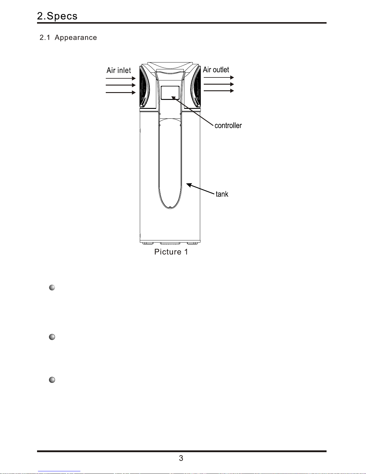
2.1) Appearance
2.2) Characteristics
2.3) Operational Principle
2.4) Dimensions
2.5) Technical Data
3. System Features
4. Installation
4.1) Pipeline connection sketch
4.2) Handling and transportation
4.3) Installation clearances
4.4) Cable connection
4.5) Trial running
5. Operation
5.1) Function of wire controller
5.2) Controller Operation
6. Maintenance and repair
7.1) Unit parameters
7. Appendix
6.2) Troubleshooting guide
6.1) Maintenance
7.2) PCB Description
7.3) Detailed parts overview
7.4) Caution
7.5) Earthing methodology
7.6) Use of the P&T valve
Warranty

Contents
Contents
1. Safety Precautions
1
2. Specifications
3
2.1) Appearance
3
2.2) Characteristics
3
2.3) Operational Principle
4
2.4) Dimensions
5
2.5) Technical Data
6
3. System Features
7
4. Installation
8
4.1) Pipeline connection sketch
8
4.2) Handling and transportation
9
4.3) Installation clearances
10
4.4) Cable connection
13
4.5) Trial running
13
5. Operation
14
5.1) Function of wire controller
14
5.2) Controller Operation
16
6. Maintenance and repair
27
7.1) Unit parameters
28
7. Appendix
28
6.2) Troubleshooting guide
27
6.1) Maintenance
27
7.2) PCB Description
28
7.3) Detailed parts overview
29
7.4) Caution
31
7.5) Earthing methodology
32
32
7.6) Use of the P&T valve
33
7.7) Use of the overheating protector
Warranty
34
33
7.8) Draining the water tank
1
1.Safety Precautions
!
To prevent personal injury and avoid causing damage to the unit, please take the time to
read the information documented in this manual.
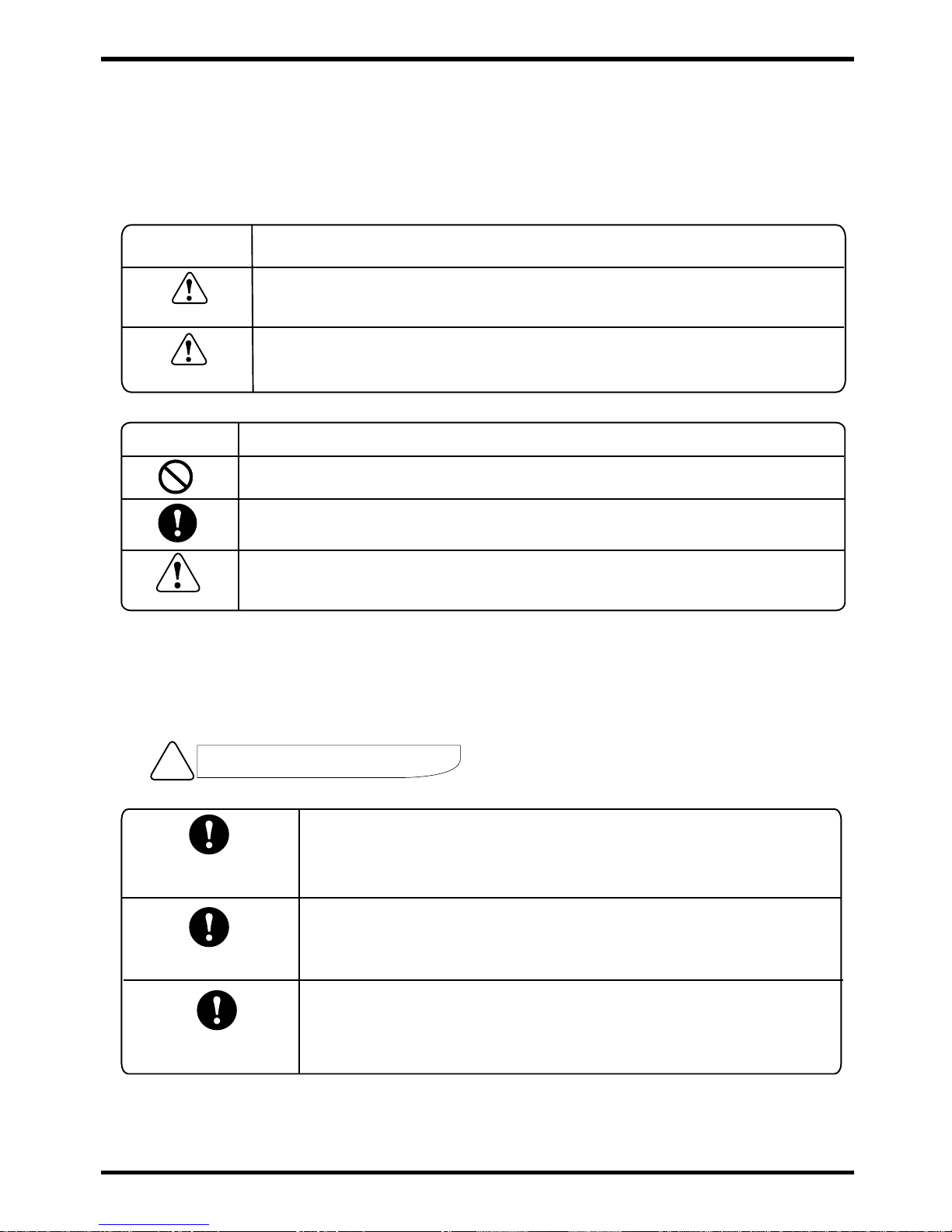
Icon
Meaning
Failure to pay attention to this may lead to serious injury or death.
Failure to pay attention to this may lead to injury or loss of material.
WARNING
INSTALLATION WARNING
Icon
Meaning
Compulsory - The listed action must be implemented.
Please pay attention to what is indicated.
Prohibited (Next to this icon)
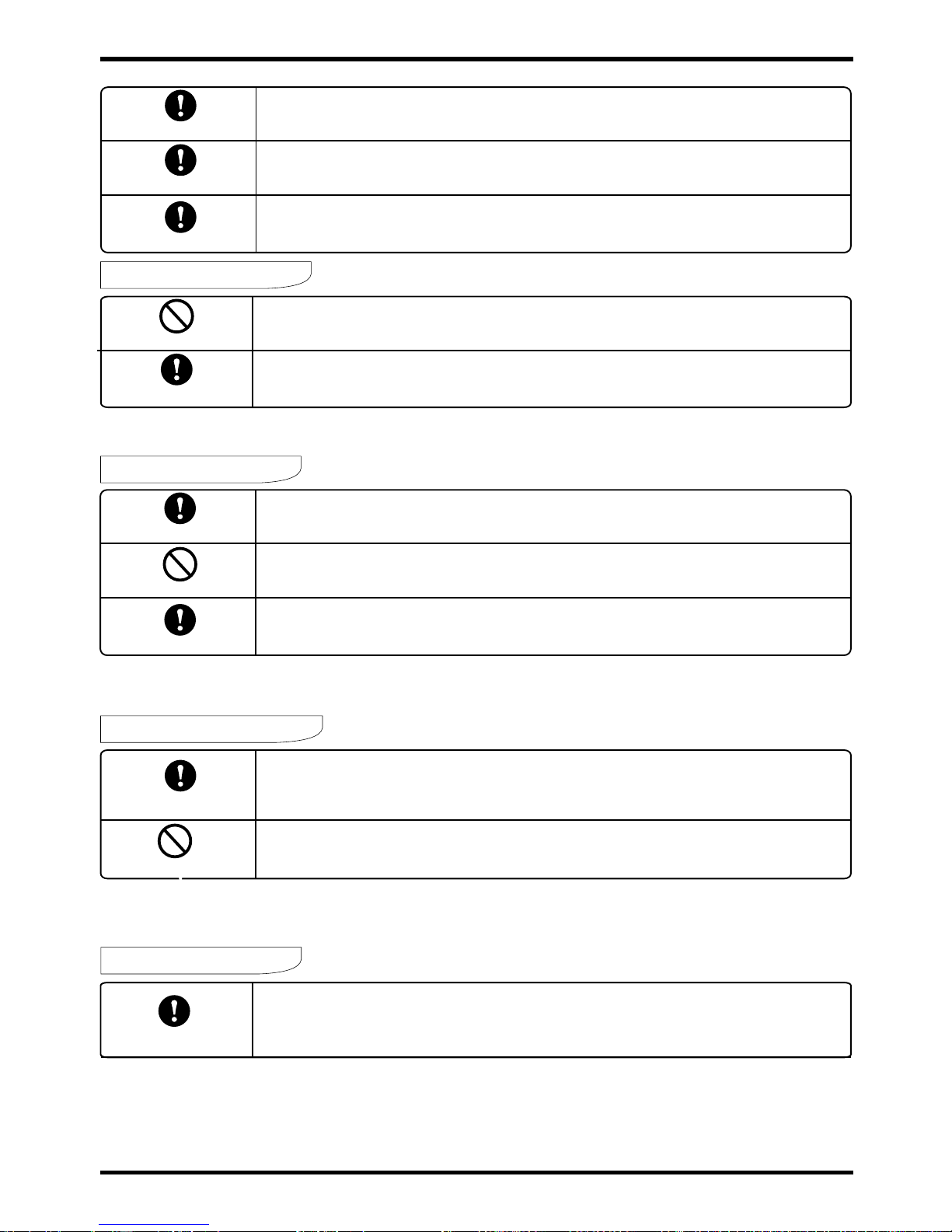
The heat pump must be installed by qualified persons. Improper
installation could result in electrical shock /water leakage or fire.
Please ensure that the unit and power connections have a good
earth. Failure to do this may cause electrical shock.
Professional installer
required
Earthing is required
ATTENTION
Check drainage fittings
Before installation, make sure there are no leaks on the plumbing
and drainage fittings.
1.Safety Precautions
Installation position
Circuit breaker required
OPERATION WARNING
Shut off the power
MOVE AND REPAIR
OPERATION ATTENTION
Shut off the power
USAGE WARNING
Usage warning
1.Safety Precautions
2
Installation position
Fixing the unit
Circuit breaker required
The unit MUST NOT be installed near flammable gas.
Ensure that the base you are installing on is level and stable.
This unit requires a circuit breaker. failure to do so could result in an
electrical shock or fire.
OPERATION WARNING
Prohibited
Shut off the power
Do not put fingers or any other objects into the fan. Children should be
kept clear of this appliance.
In the event of a unit malfunction please shut the power off and contact your service
engineer.
MOVE AND REPAIR
Important
If the heat pump needs to be relocated or installed again, only use an authorised
dealer or qualified persons.
It is prohibited for the end user to repair the unit . Failure to use a qualified
technician may lead to serious injury and/or damage to the unit.
Should the heat pump need to be repaired, only use an authorised dealer or
qualified technician.
Prohibited
Important
OPERATION ATTENTION
Shut off the power
Turn the power off before cleaning the unit.
Prohibited
Do not spay flammable aerosols onto the unit, as this could result in a fire.
USAGE WARNING
Usage warning
Danger - High temperature water and hot fittings. Do not touch.
Setting the water temperature too high can cause burns and scalds.
Do not attempt to repair yourself - contact Evoheat for advice.
Smart and efficient unit
The operational costs can be up to 75% less than that of an electric water heater, and can
be installed in locations which are unsuitable for solar hot water heating.
2.2 Characteristics
Easy to operate
Featuring an easy to use timer for both start and stop operations, with a controller to set the
desired water temperature.
Safe and environmentally friendly
Produces no harmful gases along with no open flame, making the unit safe to work with
when installing.
2. Specs
2.3 Operational Principle
Heat Pump System Theory:
(1) Using a small power input to drive the compressor, the power used is Q1.
(2) While the unit is running, the power that comes ambient air is Q2 (from the refrigerant
transformation).
(3) The energy that the water gets from the unit is Q3.
(4) According to the law of conservation of energy:
﹛ Sum of input power = sum of output power Q1+Q2 = Q3
﹛ In standard working conditions, the power that heat pump gets from the environment is about
3.2 times the power input, Q2 = 3.2 x Q1
so: Q3 = Q1+Q2 = Q1+3.2Q1= 4.2Q1
Which means you can get 4.2Q1 from heat pump if you spend Q1 energy. Which means the
energy that you can get from heat pump after using 1 kW of electricity is equal to the energy that
you get from electrical element heater after using 4.2 kW of electricity. This makes the hot water
heat pump is one of the most energy efficient heating equipment available on the market today..
4
2. Specs
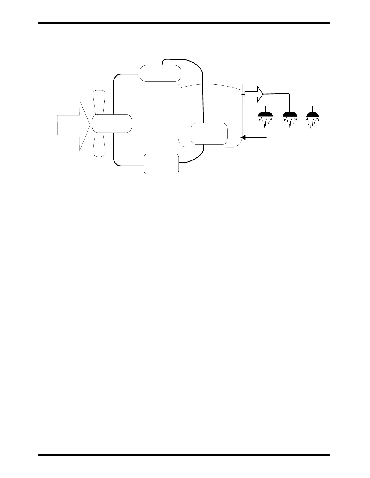
2.3 Operational Principle
4
Air from
outside
Hot water
Low temp.
Compressor
Compressor
Thermal
expansion
valve
Water supply
Tank
Picture 2
Air
exchanger
Water
exchanger
Heat Pump System Theory:
(1) Using a small power input to drive the compressor, the power used is Q1.
(2) While the unit is running, the power that comes ambient air is Q2 (from the refrigerant
transformation).
(3) The energy that the water gets from the unit is Q3.
(4) According to the law of conservation of energy:
﹛ Sum of input power = sum of output power Q1+Q2 = Q3
﹛ In standard working conditions, the power that heat pump gets from the environment is about
3.2 times the power input, Q2 = 3.2 x Q1
so: Q3 = Q1+Q2 = Q1+3.2Q1= 4.2Q1
Which means you can get 4.2Q1 from heat pump if you spend Q1 energy. Which means the
energy that you can get from heat pump after using 1 kW of electricity is equal to the energy that
you get from electrical element heater after using 4.2 kW of electricity. This makes the hot water
heat pump is one of the most energy efficient heating equipment available on the market today..
2. Specifications
5
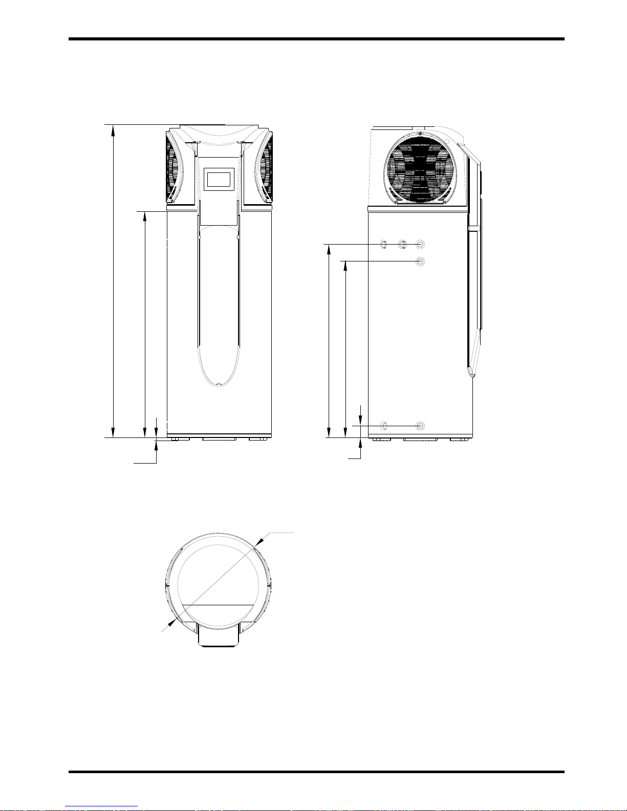
2.4 dimensions
unit-mm
MODEL: EVOHEAT 270
2. Specifications
2.5 performance parameters
Working Temp Range
(1).Ambient temperature is -7deg to 43deg(Heat Pump)
(2).The max temperature of water tank is 70
Measurement conditions:
Instant heating: Ambient temperature15DB/13WB,Water inlet 15 Water outlet 45
Operating parameters
The range of the operating water pressures: 0.15~0.7MPa
Picture 3
¦640
16
99
1435
1955
1194
1094

2. Specifications
2.5 performance parameters
6
Working Temp Range
(1).Ambient temperature is -7deg to 43deg(Heat Pump)
(2).The max temperature of water tank is 70
Measurement conditions:
Instant heating: Ambient temperature15DB/13WB,Water inlet 15 Water outlet 45
Operating parameters
The range of the operating water pressures: 0.15~0.7MPa
Model
Heating capacity
Water tank capacity
Power input
Running current
Power supply
Compressor Number
Compressor
Rated outlet water Temp.
Air volume
Nosie
Water inlet/outlet size
*Hydroboost Power heat
Net dimensions
Shipping dimensions
Net weight
Shipping weight
kW
kW
A
Deg C
3
m /h
dB(A)
inch
kW
mm
mm
kg
kg
EVOHEAT270 (PASHW015-270LD)
3.4 Heat Pump
270
0.94 Heat Pump
3.92 Heat Pump + 6.5 Hydroboost
240V~/50Hz
1
rotary
55
450
49
3/4
1.5
See the drawing
135
175
720x760x2040

3.Operation
3 min safety protect
If the unit stops and you re start the unit or turn it on manually, the unit will not start to run
again for approx 3 minutes. This is a protection feature to safe guard the compressor.
In low ambient conditions the heating output decreases. See page __ for further
information.
Heating capacity
In order to use the unit correctly, please run the unit at environment temperature -7→-43→.
The unit includes sophisticated electronic devices, prohibited to use water from lake, untreated
river water and groundwater!
Working conditions
Defrosting
In heating mode the unit will defrost automatically, maximizing the heating efficiency (Lasting 2 10 minutes).
The fan motor will stop running whilst the unit is defrosting.
Overheating protection
When the water temperature reaches 75deg C, the power of the unit will be cut and must be
manually reset. See page __ for more information.
Water pressure protectiontemperature or
A P&T valve MUST be installed in the tank. When the tank pressure reaches 0.85MPa or
when the tank temperature reaches 93deg C, the P&T valve will open automatically so as
to reduce the pressure or temperature decrease.
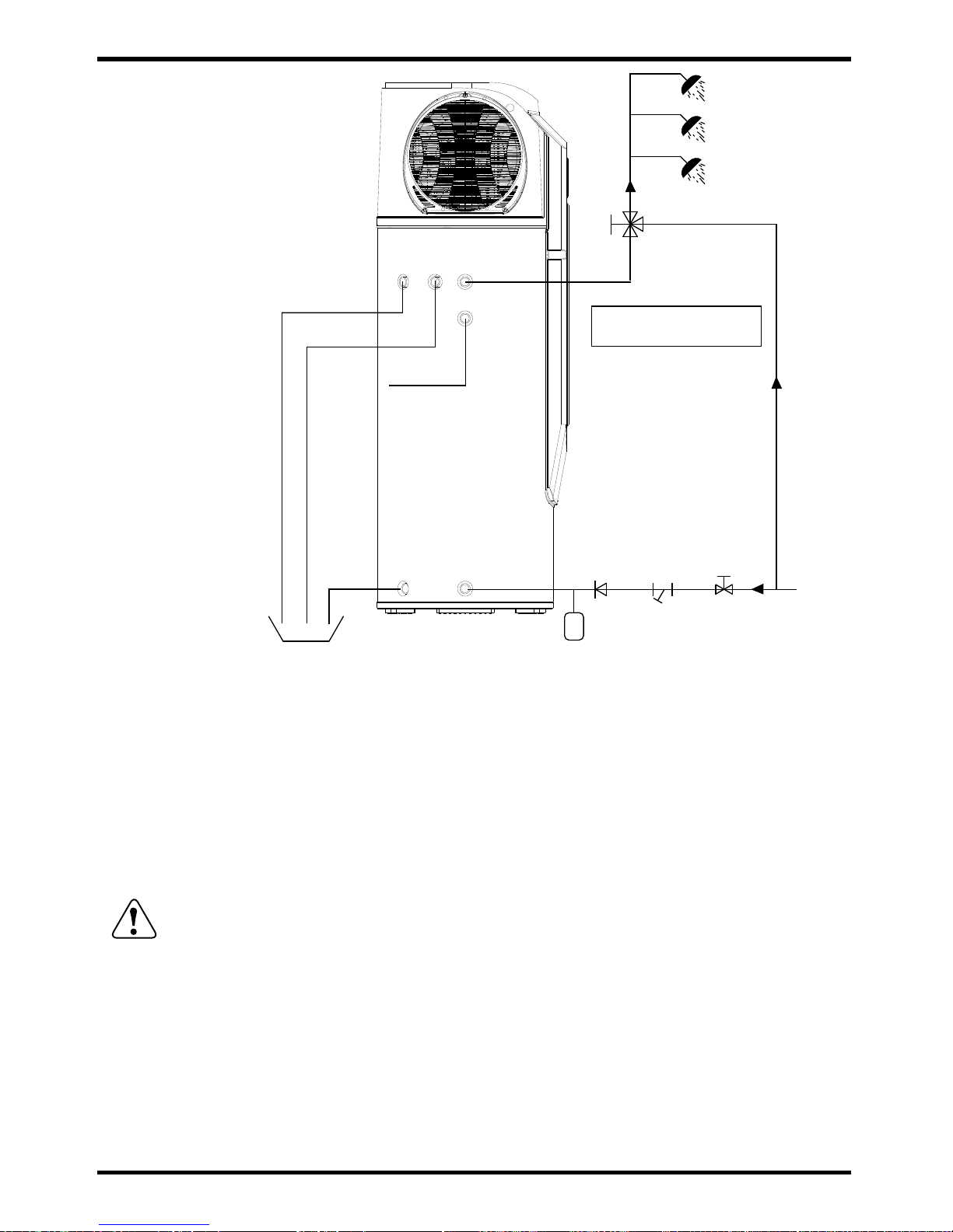
4.1 Pipeline connection sketch
4. Installation
7
Sanitech high temp sanitization
The Evoheat 270 is fitted with Sanitech. the Sanitech system will heat the tank water to 70
degrees for one 30min period every week at midnight. Please be aware of very high
temperature water outlet at this time.
8
4.1 Pipeline connection sketch
4. Installation
Picture 4
ATTENTION
Pipeline connection explanation
Installation of the water inlet or outlet pipes: The specification of the water inlet and
outlet thread is BSP3/4”(internal thread).Pipes must be heat-resistant and durable.
Installation of the pipe for P&T valve: The spec of the valve connecting thread is
BSP3/4”(internal thread).After installation, please confirm that the plumbing outlet is
exposed to the air. When flexible plumbing is connected to the pressure relief
outlet of this valve, please confirm that the plumbing is vertical and exposed to the
air.
Water Inlet
Y-shaped Filter
Tap Water
Thermal expansion tank
(if required)
Barrel-drain
Drainpipe
Condensate Outlet
P&T Valve
Water Outlet
Notice:
Tempering valve required
Magnesium
Anode
ATTENTION: The P&T valve attached to the unit MUST be installed, or it will cause
damage to the unit and pose a serious risk to passersby.
Installation MUST comply with AS/NZS3500.4 and all other relevant Australian
Standards and Industry Codes.
Do not use stainless steel fittings to connect directly with other metals to prevent
galvanic corrosion.
If installed outdoors all fittings and insulation must be weather resistant
.

9
4. Installation
4.2 Freight and Transportation
As a rule, the unit should be stored and/or transported in its shipping container in an upright
position and without water charge. For transport over short distances, and provided due care
is exercised, an inclination angle of up to 30 degrees is permitted. During transport and
storage, ambient temperatures of - 10 to +60deg C are permissible.
4.2.1 Transport using a forklift
When transported by a fork lift, the unit must remain mounted on the pallet. The lifting speed
should be kept to a minimum. Due to its top-heaviness, the unit must be secured against
tipping over. To prevent any damage or injury, the unit must be placed on a level surface.
4.2.2 Manual transport
For the manual transport, the wooden pallet can be used for bottom part.
Using ropes or carrying straps, a second or third handling configuration is possible. With this
type of handling, care must be taken that the maximum permissible inclination angle of 60
degrees is not exceeded. If transport in an inclined position cannot be avoided, the unit should
be left to rest at least one hour after it has been moved into final position before operation.
CAUTION! High center of gravity, Place on a level surface!
Picture 5
4. Installation
Before installation, please ensure that you leave space as shown below for maintenance
The unit must be installed on the ground on a solid level surface capable of holding the full weight of
the unit.
4.2A Recommended household size
The below recommendations are based on heat pump only mode.
Higher occupancy levels are able to be achieved with the
Hydroboost heater activated
Notice: High usage of hot water and other factors could affect this
recommendation.Please consult your dealer if you have special requirements.
Household Size
Up to 6 people
model
Evoheat 270
 Loading...