

Page 1

Installation and Instruction Manual
Inverter Air Source Water Heat Pump
Floor heating and Air-con Unit
Hero Series Manual
Page 2

CONTENT
1 Preface
1
3 Specification
5
(3
) Specification data
6
(4) Unit Dimension
7
8
4 Installation
9
12
5 Usage
7 Appendix
22
25
2 Safety Precaution
2
(1) Mark notes
2
(2) Icon Notes
2
(3) Warning
3
(1) Nomenclature of the heat pump
(2) Appearance and Structure of the heat pump
5
5
8
9
9
10
10
1
1
11
12
14
24
24
26
27
10
(1) Application of heat pump
(2) Choose a right heat pump unit
(
3) Installation place
(4) Installation method
(
5) Water loop connection
(
6) Power supply connection
(
7) Location of the unit
(8) Transit
(9) Trial Running
(1) Interface
(3) Usage Of Wire Controller
6 Maintenance
(1) Appendix 1
(2) Appendix 2
(
3
) Appendix 3
(
4) Appendix 4
(
5) Appendix 5
(
6) Appendix 6
(
7) Appendix 7
(4) Attention
4
(1) Fault code
(2) Failure and Solution
(5) Electronic Control Error Table
(4) Error Interface
18
20
22
23
26
28
29
4 Quiet running
High quality and efficient compressor, fan and water pump is used to ensure the lo w
noise level with insulation.
5 Good heat exchange rate
Failure to comply with these recommendations will invalidate the warranty.
2 Nice appearance
pump included which is very easy for installation.
3 Flexible installation
1 Advanced controlling
running parameters of the heat pump. Centralized co ntrolling system can control several
units by PC.
It is vital that the below instructions are adhered to at all times to k eep the warranty.
6 Large working range
as -15 degrees for heating.
Preface
12
(2) Function and Display Icon
(6) Controller interfaces and definitions
21
Page 3

The manufacture of this product will not be held responsible if someone is injured or
the unit is damaged, as a result of improper installati on, debugging, unnecessary
maintenance which is not in line with this man ual.
This manual includes all the necessary inf ormation about installation, debugging,
discharging and maintenance. Please re ad this manual carefully before you open or
maintain the unit.
4 Quiet running
High quality and efficient compressor, fan and water pump is used to ensure the lo w
noise level with insulation.
5 Good heat exchange rate
The heat pump unit use special designed heat exchanger to enhance whole efficiency.
The unit must be installed by qualified pers onnel.
—The unit can only be opened or repaired by qualified installer or an authorised dealer.
—Use genuine standard spare parts only.
—Maintenance and operation must be carrie d out according to the recommended time and
frequency, as stated in this manual.
Failure to comply with these recommendations will invalidate the warranty.
2 Nice appearance
The heat pump is designed with beautiful looking. The monobloc one has the water
pump included which is very easy for installation.
3 Flexible installation
The unit has smart structure with compact body, just simple outdoor installation is needed.
This series of heat pump unit owns following features:
1 Advanced controlling
The PC microcomputer based controller is available for the users to review or s et the
running parameters of the heat pump. Centralized co ntrolling system can control several
units by PC.
It is vital that the below instructions are adhered to at a ll times to keep the warranty.
Inverter ir ource ater eat umpa s w h p is a kind of high efficiency, energy saving and
environment friendly equipment, whic h is mainly used for house warming. It can work with
any kind of indoor unit such fan coil, radiato r, or floor heating pipe, by provide warm or hot
water. One unit of monobloc heat pump can also wo rk with several indoor units.
The air source water heat pump unit is designe d to have heat recovery by using super
heater which can provide hot water for sanit ary purpose.
6 Large working range
This series of heat pump is designed to work under different working conditions as low
as -15 degrees for heating.
In order to provide the customers with high quality, strong reliability and good versatility
product, this heat pump is produced by strict design an d manufacture standards.
Preface
1
Page 4
Safety Precaution
Mark
Icon
Meaning
Meaning
A wrong operation may lead to death or heavy injury on people.
A wrong operation may lead to harm on people or loss of material.
Prohibition. What is prohibited will be nearby this icon
Compulsory implement. The listed action need to be taken.
ATTENTION (include WARNING)
Please pay attention to what is indicated.
Mark Notes
Icon notes
WARNING
ATTENTION
To prevent the users and others from the harm of this unit, and avoid damage
on the unit or other property, and use the heat pump properly, please read this
manual carefully and understand the following information correctly.
Safety Precaution
2
Page 5
安装前注意事项
The heat pump must be installed by qualified personals,
to avoid improper installation which can lead to water
leakage, electrical shock or fire.
Please make sure that the unit and power connection
have good earthing, otherwise may cause electrical shock.
Installation
Professional installer
is required.
Earthing is required
Warning
Safety Precaution
Meaning
Operation
Meaning
PROHIBITION
Shut off the power
DO NOT put fingers or others into the fans and evaporator
of the unit, otherwise harm may be occurred.
When there is something wrong or strange smell, the power
supply need to be shut off to stop the unit. Continue to run
may cause electrical short or fire.
Move and repair
Entrust
Prohibit
Entrust
When the heat pump need to be moved or installed again,
please entrust dealer or qualified person to carry it out.
Improper installation will lead to water leakage, electrical
shock, injury or fire.
It is prohibited to repair the unit by the user himself, otherwise
electrical shock or fire may be occur.
When the heat pump need to be repaired, please entrust
dealer or qualified person to carry it out. Improper movement
or repair on the unit will lead to water leakage, electrical
shock, injury or fire.
Meaning
3
Page 6
Switch off
the power
Prohibition
Please switch off the power for clean or maintenance.
It is prohibited to use copper or iron as fuse. The right fuse
must be fixed by electrician for the heat pump.
It is prohibited to spray the flammable gas to the heat pump,
as it may cause fire.
Installation
Operation
Prohibition
安装前注意事项
ATTENTION
Check the
installation basement
Please check the installation basement in a period (one month),
to avoid any decline or damage on the basement, which may
hurt people or damage the unit
Safety Precaution
Meaning
Fix the unit
Installation Place
Need
circuit breaker
The unit CANNOT be installed near the flammable gas.
Once there is any leakage of the gas, fire can be occur.
Make sure that the basement of the heat pump is strong
enough, to avoid any decline or fall down of the unit
Make sure that there is circuit breaker for the unit, lack of
circuit breaker can lead to electrical shock or fire.
Meaning
4
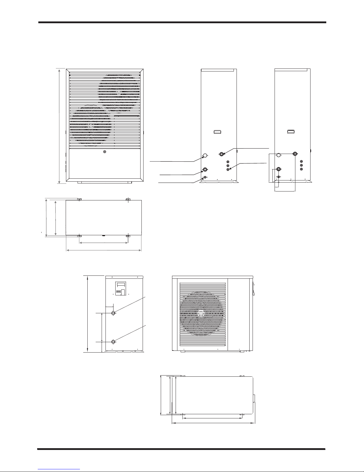
Specification
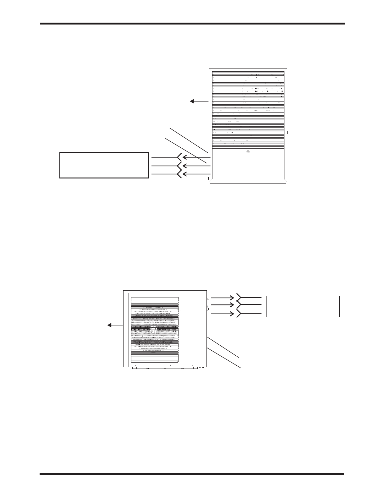
1. Appearance and Structure of the heat pump
The longest distance of installing the
remote controller is 200 meters.
Air outlet in horizontal
direction
Page 7
Specification
1. Appearance and Structure of the heat pump
The longest distance of installing the
remote controller is 200 meters.
Air outlet in horizontal
direction
Water intlet tube
Remote Controller
(Manually)
Water outlet tube
5
Air outlet in horizontal
direction
Water outlet tube
Water intlet tube
The longest distance of installing the
remote controller is 200 meters.
Remote Controller
(Manually)
H15A
H8A
Page 8

2. The data of unit
Specification
Cooling working condition:(DB/WB)3 5℃/24℃, (Outlet/Inlet) 7℃/12℃.
Heating working condition: (DB/WB) 7℃/6℃. (Outlet/Inlet) 35℃/3 0℃.
BS EN 14511-1-2013 Air conditioner, whole liquid cooling machine, e lectric compressor.
Part2: Test condition Part3:Test method Part4:related requirements.
6
Model
Cooling Capacity
Heating Capacity
Electric Heating Power
Cooling Power Input
Heating Power Input
Operation Electric Current(cooling /heating)
Cooling Capacity Range
Heating Capacity Range
Cooling Power Input Range
Heating Power Input Range
Power Supply
Compressor Quantity
Compressor Model
Fan Quantity
Fan Power Input
Fan Rotate Speed
Noise
Water Pump Input
Max water head
Water Connection
Water Flow Volume
External Pressure
Unit Net Dimensions (L/W/H)
Unit Shipping Dimensions (L/W/H)
Net Weight
Shipping Weight
kW
BTU/h
kW
BTU/h
kW
kW
kW
A
kW
kW
kW
kW
W
RPM
dB(A)
kW
m
inch
3
m /h
m
mm
mm
kg
kg
H15A
10
34000
15
51000
3.0
3.1
3.1
14.1/14.1
6.0~15.0
6.0~18.0
1.6~6.0
1.6~7.0
230V~/50Hz
1
Scrolll
2
110×2
850
58
0.18
12.5
1 1/4
2.5
10
1000*465*1475
1050*510*1500
See nameplate
See packa ge label
H8A
7
23800
9
30600
3.0
2.6
2.6
11.8/11.8
2.0~10
2.5~11.5
1.0~3.4
0.8~3.4
230V~/50Hz
1
Rotary
1
110
850
54
0.18
12.5
1
1.6
10
980*465*900
1010*490*920
See nameplate
See packa ge label
Specification
505
Page 9
7
3 Unit dimension
Specification
Mode ls: H15 A
1000
505
465
647
1475
Wat er inl et 1 1/4' '
Con densa te outl et 1 1/4' '
Wat er outl et 3/4' '
Wat er outl et 1 1/4' '
Wat er pump w ire
369 .5
170
266 .5
51.5
7
Mode ls:H8A
Wat er outl et 1''
Wat er inl et 1''
980
700
465 440
900
338
121
90
Page 10
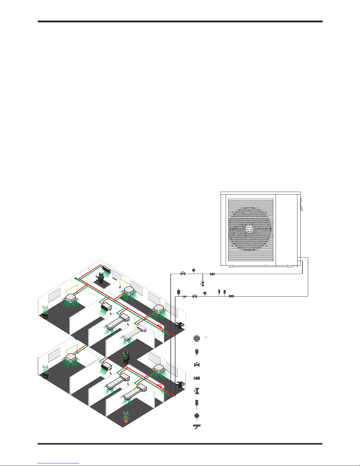
4 Installation method
2 Choose a right heat pump unit
2.1 Based on the local climate condition, co nstruction features and insulation level,
calculate the required cooling(heati ng) capacity per square meter.
2.2 Conclude the total capacity which will b e needed by the construction.
2.3 According to the total capacity needed, c hoose the right model by consulting the heat.
pump features as below:
Heat pump features
Cooling only unit: chilled water outlet tem p. at 5-15 , maximum ambient temp. at 43 .
Heating and Cooling unit:for cooling chilled water outlet temp. at 5-15 ,maximum
ambient temp. at 43 . For heating, warm water inlet temp . at 40-50 , minimum ambient
temp. at -10 .
Unit application
a s w h p is used for house, office, hotel, and so forth, which
need heating or cooling separately, with each area need to be control led.
The unit can be installed on any place outdoor which can carry heavy mac hine such
as terrace, housetop, ground and so on.
3 Installation place
Installation
Installation
1 Application of heat pump
1.1 Only for air-con
WATER COUPLING
AUTOMATIC AIR VENT
CHECK-VALVE FOR WATER
FLEXIBLE CONNECTION FOR WATER
DIRTY DRAI N
WATER THERMOMETER
WATER PRESSURE METER
WATER FILTER
8
1. Plate heat exchanger
Use the SWEP efficient heat exchanger with small size a nd high efficiency.
2.Environmentally friendly refrigerant
Use the new generation of environmentall y friendly refrigerant R410, which is harmless to
the ozone sphere.
3. Heating in frigid environment.
Optimized designed unit can achieve the he ating function normally even when the ambient
temperature is -15℃.
4. Spraying condensation
The water-cooling system will be opened automatically to guarantee the normal operation
of cooling when the ambient temperature is higher than 30℃.
Unit features
Page 11
4 Installation method
The heat pump can be installed onto the concrete basement by expansi on screws, or
onto a steel frame with rubber feet which can be p laced on the ground or housetop.
Make sure that the unit is placed horizontal ly.
2 Choose a right heat pump unit
2.1 Based on the local climate condition, co nstruction features and insulation level,
calculate the required cooling(heati ng) capacity per square meter.
2.2 Conclude the total capacity which will b e needed by the construction.
2.3 According to the total capacity needed, c hoose the right model by consulting the heat.
pump features as below:
Heat pump features
Cooling only unit: chilled water outlet tem p. at 5-15 , maximum ambient temp. at 43 .
Heating and Cooling unit:for cooling chilled water outlet temp. at 5-15 ,maximum
ambient temp. at 43 . For heating, warm water inlet temp . at 40-50 , minimum ambient
temp. at -10 .
℃ ℃
℃
℃ ℃
℃
Unit application
a s w h p is used for house, office, hotel, and so forth, which
need heating or cooling separately, with each area need to be control led.
Inve rter ir ource a ter eat ump
There must be enough space around the unit for maintenance.
The place is free from heat radiation and othe r fire flame.
There must be not obstacles near the air inlet a nd outlet of the heat pump.
A place which is free from strong air blowing.
There must be water channel around the heat pu mp to drain the condensing water .
The location must have good ventilation.
The unit can be installed on any place outdoor which can carry heavy mac hine such
as terrace, housetop, ground and so on.
A pall is needed in winter to protect the heat pump from snow.
3 Installation place
Installation
9
Page 12

Installation
9 Trial Running
8 Transit
When the unit need to be hung up during installa tion, a 8
meters cable is needed, and there must be soft material
between the cable and the unit to prevent dama ge to
the heat pump cabinet. (See picture 1)
DO NOT touch the heat exchanger of the heat pump with fingers or other objects!
5 Water loop connection
Please pay attention to below matters when the water pipe is connected:
Try to reduce the resistance to the water from the piping.
The piping must be clear and free from dirty and b locks. Water leakage test must be
carried out to ensure there is no water leakin g. And then the insulation can be made.
Attention that the pipe must be tested by pressure separately. DO NOT test it together
with the heat pump.
The flow switch is installed inside of the hea t pump, check to ensure that the wiring and
action of the switch is normal and controlle d by the controller.
Try to avoid air stayed inside of the water pipe, and there must be air vent on the top
point of the water loop.
There must be thermometer and pressure met er at the water inlet and outlet, for easy
inspection during running.
There must be expansion tank on the top point of t he water loop, and the water level in
the tank must be at least 0.5 meter higher than the top point of the water loop.
6 Power supply connection
Open the front panel, and open the power supply access.
If the outside water pump is needed, please insert the power supply wire into the wire
access also and connect to the water pump term inals.
The power supply must go through the wire acce ss and be connected to the power
supply terminals in the controlling box. Then connect the 3-sign al wire plugs of the
wire controller and main controller.
If an additional auxiliary heater is need to be controlled by the heat pump controller,
the relay (or power) of the aux-heater must be c onnected to the relevant output of
the controller.
7 Location of the unit
Installation
。
The minimum ventilation distance in diag ram 1.
A
B
Barrier
Barrier
Air Inlet
Air Outlet
C
D
Barrier
Maintenance
Space
Barrier
The picture shows the location of horizontal air outlet unit.
Requirements
A>500mm; B>1500mm;
C>1000mm;D>500mm
!
Attention
10
Page 13

Installation
Inspection before trial running
Check the indoor unit, and make sure that the pipe connection is right and the relevant
valves are open .
Check the heat pump unit including all of the sc rews and parts of the heat pump to see if
they are in good order. When power on, review the i ndicator on the controller to see if
there is any failure indication. The gas gauge can be connected to the check valve to
see the high pressure(or low pressure) of th e system during trial running.
Check the water loop, to ensure that the water inside of th e expansion tank is enough, the
water supply is good, the water loop is full of wa ter and without any air. Also make sure
there is good insulation for the water pipe.
Check the electrical wiring. Make sure tha t the power voltage is normal, the screws are
fastened, the wiring is made in line with the di agram, and the earthing is connected.
Trial running
Start the heat pump by press " " key on the controller. Check whether the w ater pump is
running, if it runs normally there will be 0.2 M Pa on the water pressure meter.
When the water pump runs for 1 minutes, the compressor wi ll start. Hear whether there is
strange sound from the compressor. If abnormal sound occurs please stop the unit and
check the compressor. If the compressor runs well please look for the pressure meter
of the refrigerant.
9 Trial Running
Then check whether the power input and runni ng current is in line with the manual. If not
please stop and check.
Review whether the outlet water temperat ure is stable.
The parameters of the controller are set by the factory, it is not allowed to change then
by user himself.
Adjust the valves on the water loop, to make sure that the ho t(cool) water supply to each
door is good and meet the requirement of heati ng(or cooling).
8 Transit
When the unit need to be hung up during installa tion, a 8
meters cable is needed, and there must be soft material
between the cable and the unit to prevent dama ge to
the heat pump cabinet. (See picture 1)
WARNING
DO NOT touch the heat exchanger of the heat pump with fingers or other objects!
Picture 1
11
Page 14

Usage
1.Interface
2.Function and Display Icon
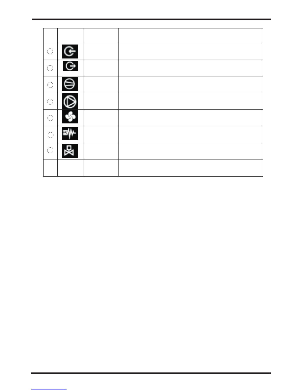
NO.
Icon
Key name
Key functions
1
2
3
4
On/Off
Mode
Up
Down
Long press "Mode", to switch between cooling
and heating
In the state of defrosting, the icon Def is on
In the state of cooling, the icon Cool is on
In the state of heating, the icon Hot is on
5
Fan Speed
Short press "Fan Speed", to enter the Query interface
6
7
8
In OFF state, long pr ess "ON/OFF", to en te r the Startup inter fa ce
In ON state, long pre ss " ON/OFF", to ent er t he Shutdown inter fa ce
Short press "UP", to modify the temperature or clock
Short press "DOWN", to modify the temperature or clock
12
Cooling
Heating
Def
Usage
Page 15
Usage
13
NO.
Icon
Key name
Key functions
9
10
Outlet
Electric
Heating
4-way valve
Outlet icon
When the Electric Heating starts up, in the main
display area, the Electric Heating status icon i s on , an d
when the Electric Heating shuts down, the icon is off.
When the 4-way valve starts up, in the main display ar ea ,
the 4-way valve status icon is on, and when the 4-way
valve shuts down, the icon is off.
Inlet
Inlet icon
Compressor
When the compressor starts up, in the main display
area, thecompressor status icon is on, and when
the compressor shuts down, the icon is off.
Pump
When the Pump starts up, in the main display area, the
Pump status icon is on, and when the Pump shuts down,
the icon is off.
Fan
When the Fan starts up, in the main display area, the
Fan status icon is on, and when the Fan shuts down,
the icon is off.
11
12
13
14
15
Page 16

14
Usage
3.Usage Of Wire Controller
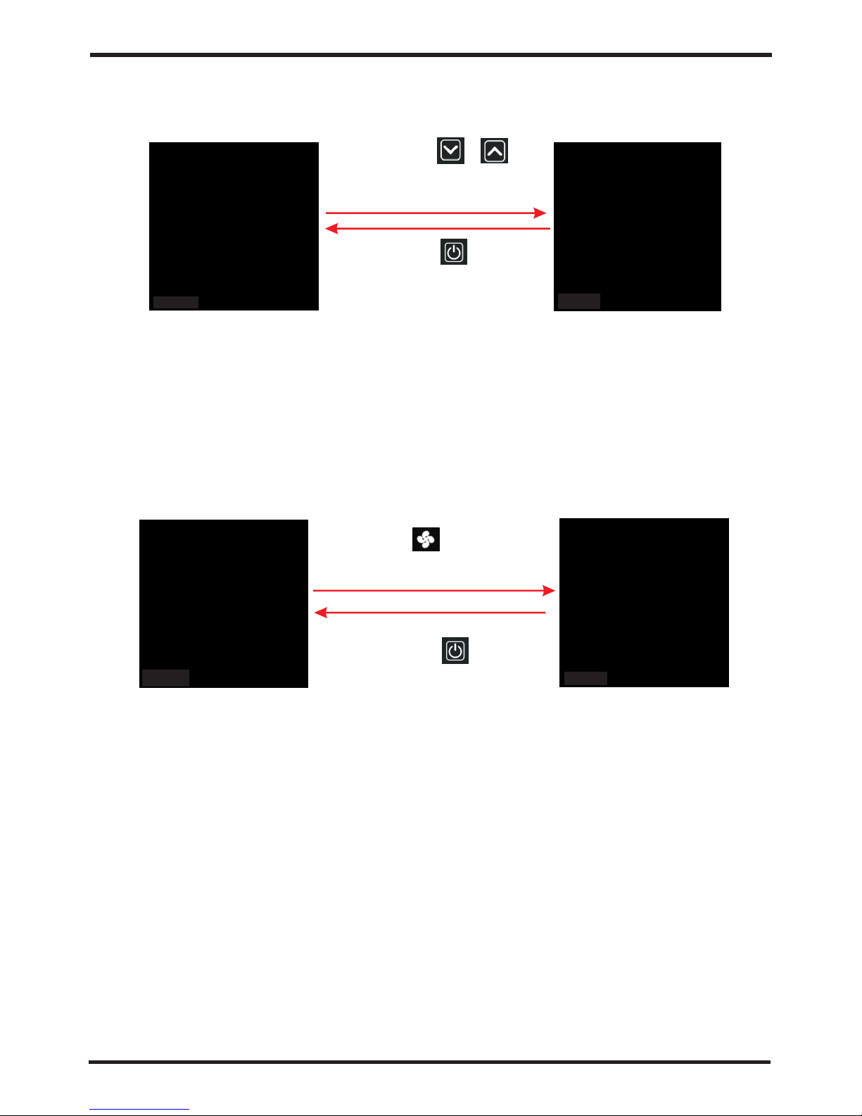
3.1 Startup & Shutdown
Note: the Startup & Shutdown operation can only be performed in the main interface.
1
enter the S tartup
interfa ce
Long pres s for
second to
For 1 minut e without
operati on, scree n out
Short pre ss any key,
back to the S tartup
interfa ce
3.2 Mode
In the main interface, long press for " "1 second, to switch between t he cooling
and heating modes.
Cooling Interface
Heating Interface
Note: 1) Without Thermostat, wired controller can be used for Startup & Shutdown;
2) With Thermostat, wired controller can only be used for Shutdown, and cannot
be used for Startup;
3) When using the remote control, wired controller is shown as below:
Startup Interface
Shutdown Interface
Def Interface
(heating mode only)
1
enter the S hutdown
interfa ce
Long pres s for
second to
Usage
Note: In the temperature setting interface, for 20 seconds without operation, the system
will automatically record the setting, and back to the main inte rface.
Page 17
15
Usage
Set tempe rature fl ashing
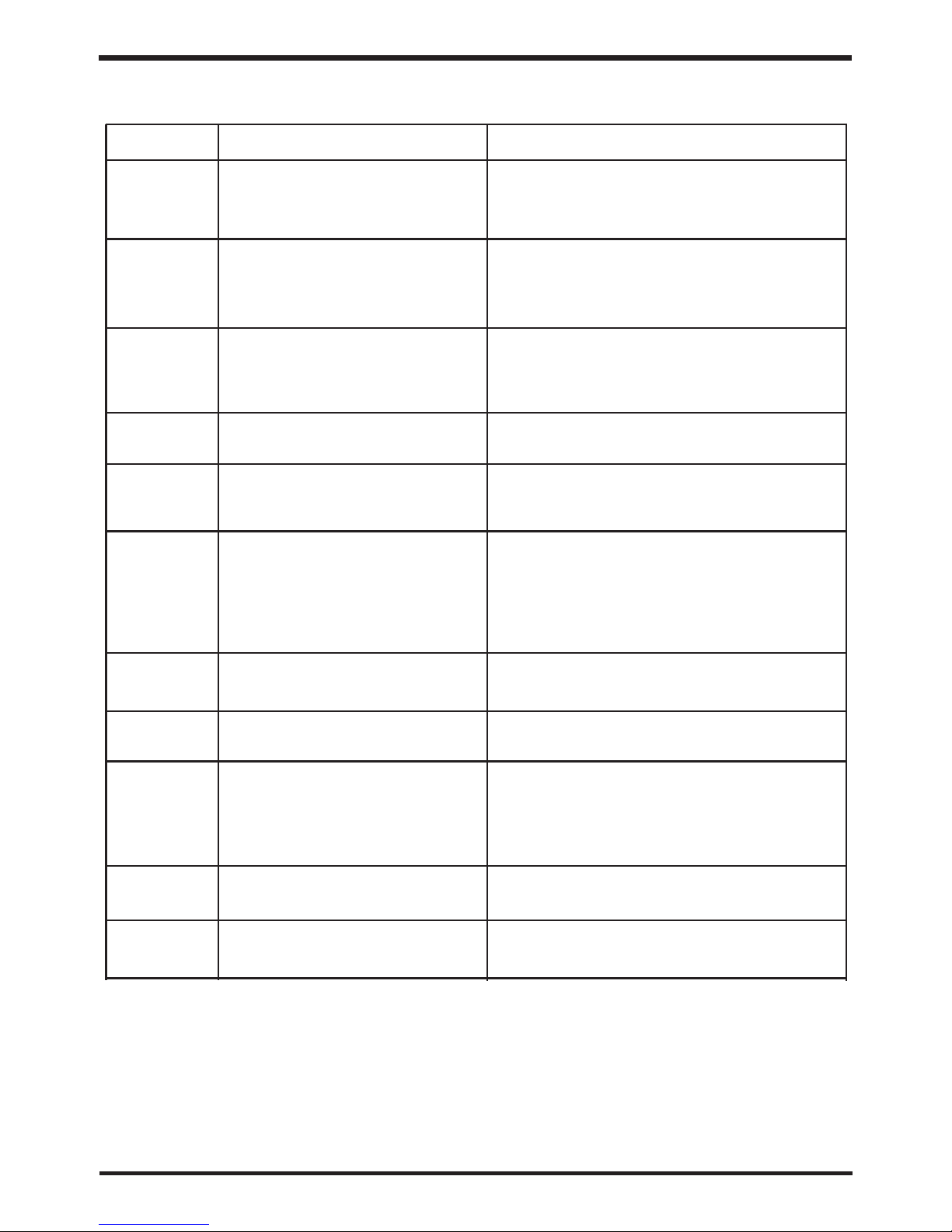
Note: In the temperature setting interface, for 20 seconds without operation, the system
will automatically record the setting, and back to the main inte rface.
Note: In the query parameter interface, it cannot automatically back to the main interface.
3.3 Temperature
Short press or to
enter thetemperature
setting interface
Short press , back
and save
3.4 State parameter query
Short press ,
to enter the Query interface;
Short press
Page 18

16
3.5 State query list:
Usage
State No
U01
U02
U03
U04
U05
U06
U07
U08
U09
U10
U11
U12
U13
U14
State Name
Inlet Temperature
Outlet Temperature
Suction Temperature
Discharge Temperature
Ambient Temperature
Coil Temperature
Low Pressure
High Pressure
Electronic Expansion Valve Steps
Compressor Actual Frequency
Compressor Setting Frequency
Suction gas Superheating/10
Discharge gas Superheating
Fan 1 Set Speed
U15
Fan 2 Set Speed
Usage
Note: In the clock setting interface, for 20 seconds without operation, the system
will automatically record the setting, and back to the main inte rface.
3.6 Clock Setting
3.6.1 Time Setting
3.6.2 Set and cancel the timing
(if connected to the thermostat, the timing function is not available)
Page 19

17
Usage
Note: In the clock setting interface, for 20 seconds without operation, the system
will automatically record the setting, and back to the main inte rface.
3.6 Clock Setting
3.6.1 Time Setting
Long press +
at the same time for
two seconds
Short press
for flashing by
the hour
Short press or
to change flashing
by the hour
Short press
for flashing by
the minute
Short press or
to change flashing
by the minute
Short press
back to the main interface
3.6.2 Set and cancel the timing
(if connected to the thermostat, the timing function is not available)
Long press
to enter "ON1" time
setting interface "ON1"
time setting interface
Short press
to enter " OFF1"
time setting
interface
Short press
for flashing by the hour
to enter "ON1" hour setting
Short press
or to set hour
For flashing by the hour
or the minute
short press
to cancel "ON1" timing
Short press again
Page 20

18
4 Error Interface
Usage
Error Code
Note:
On the Error Interface, short press "ON/OFF", back to the main interface, a nd short press
"UP" or "DOWN" to display multiple errors.
On the main interface, short press "ON/OFF" to back to the Error Interface. For 10
seconds without operation, automatically back to the Error Interface.
1).
2).
4.1 Interface
Error No.
Error Quantiy
Usage
5 Electronic Control Error Table
Page 21

19
Usage
We can use Error Code to find the cause and the solution.
Protection/Error
Error Code
Standby
Normal Startup
Inlet Temperature Error
Outlet Temperature Error
Ambient Temperature
Suction Temperature Error
Discharge Temperature Error
Low Pressure Sensor Erro
High Pressure Sensor Erro
High Pressure Protection
Low Pressure Protection
Flow Switch Protection
Winter Def Protection I
Winter Def Protection II
Def Protection
Dischange High Temperature Protection
Pump Working Environment Protection
AC Input low voltage protection
AC Input over-current protection shutdown
AC Input over-current protection alarm
None
P01
P02
P04
P07
P08
PP1
PP2
E01
E02
E03
E19
E20
E07
P81
E44
E21
E22
E23(blank)
5 Electronic Control Error Table
None
DC bus over-voltage protection
DC bus low-voltage protection
IPM over-current protection
IPM overheating protection
Radiator temperature sensor error
Power component overheating protection shutdown
Power component overheating protection alarm
IPM current sampling
Compressor over-current protection shutdown
Compressor over-current protection alarm
Input voltage phase
Compressor start-up error
Communication error between DSP and communication board
Communication error between DSP with PFC
Input voltage sampling
EEPROM Error
Compressor weak magnetic protection
PFC Error
Communication error between drive and ma in board
Communication error between main board a nd wired controller
E08
EE 8
E45
E41
E40
E39
E38
E37
E36
E35
E34(blank)
E33
E32
E31(blank)
E30
E29
E28
E27
E25
E24
Page 22

PC8002
GND
GND
GND
GND
GND
GND
GND
GND
GND
GND
GND
GND
GND
GND
GND
GND
GND
GND
GND
GND
GND
GND
GND
GND
GND
GND
GND
GND
GND
N
L
RO 01
RO 02
RO 03
RO 04
RO 05
RO 06
RO 07
RO 08
RO 09
RO 10
RO 11
RO 12
RO 13
RO 14
RO 15
GND
GND
GND
GND
GND
GND
GND
GND
GND
GND
GND
GND
GND
GND
GND
5V
12V
GND
485_B
485_A
CAN_L
GND
12V
CAN_H
12V
GND
485_B
485_A
CN
1
CN
2
CN7
CN3
CN
4
CN
9
DI5 _PWM
DO5 _PWM
DI4 _PWM
DO4 _PWM
DI3 _PWM
DO3 _PWM
DI2 _PWM
A02
DO2 _PWM
DI1 _PWM
A01
DO1 _PWM
DI1 0
DI0 9
DI0 8
DI0 7
DI0 6
DI0 5
DI0 4
DI0 3
DI0 2
DI0 1
AI2 2
AI2 1
AI2 0
AI1 9
AI1 8
AI1 7
AI1 6
AI1 5
AI1 4
AI1 3
AI1 2
AI1 1
AI1 0
AI0 9
AI0 8
AI0 7
AI0 6
AI0 5
20
6 Controller interfaces and definition s
Usage
6.1 Main bo ard interface s
Usage
NO.
1
2
3
4
5
6
7
8
9
10
11
12
13
14
15
16
17
18
19
20
21
22
Page 23

AI0 8
AI0 7
AI0 6
AI0 5
AI0 4
AI0 3
AI0 2
AI0 1
Usage
21
D01-D 02_ PWM
DI0-D I2_ PWM
NO.
Main board Instruction
NO.
Main board Instruction
1
2
3
4
5
6
7
8
9
10
11
12
13
14
15
16
17
18
19
20
21
22
23
24
25
26
27
28
29
30
31
32
33
34
35
36
37
38
39
40
41
N
L
RO 01
RO 02
RO 03
RO 04
RO 05
RO 06
RO 07
RO 08
RO 09
RO 10-RO 18
AI 01
AI 02
AI 03
AI 04
AI 05
AI 06
AI 07
AI 08-AI 20
AI 21
AI 22
DI 01
DI 02
DI 03
DI 04
DI 05
DI 06
DI 07
DI 08-DI 10
A 01-A 02
12V
485-B
485-A
GND
CAN-L
CAN-H
CN1
CN2-CN4
Power Null Wire
Power Live Wire
Not Used
Pump
4-way valve
Fan
Not Used
Def Heating
Crankshaft Heating
Spray Valve
Auxiliary Electric Heating
Not Used
Inlet Temperature Sensor
Outlet Temperature Sensor
Discharge Temperature Sensor
Not Used
Suction Temperature Sensor
Coil Temperature Sensor
Environment Temperature Sens or
Not Used
Suction pressure input
Discharge pressure input
High voltage switch input
Low voltage switch input
Flow switch input
Emergency switch input
Mode Switch
Master and slave switch
Electri c heating o verload
protect ion switc h
Not Used
Not Used
Not Used
Not Used
Wired Controller 12V
Wired Controller 485-B
Wired Controller 485-A
Wired Controller GND
Not Used
Not Used
Electronic Expansion Valve A
Not Used
Page 24

22
A. Form of Troubleshooting
Check whe ther ther e is fault on
pressur e switch or r efriger ant loop
Check whe ther syst em compre ssor
is in norma l operati on
Protect ion/fau lt
Standby
Normal bo oting
Wat er inlet te mp. senso r error
Ambient tem p. sensor e rr or
Antifre ezing pro tection
Wat er flow pro tection
Cause
Wat er inlet te mp sensor i s in open
circuit o r short cir cuit
Check and rep lace temp . se nsor
Wat er outlet t emp senso r is in
open circ uit or shor t circuit
Ambient t emp senso r is in open
circuit o r short cir cuit
Check and rep lace temp . se nsor
Check and rep lace temp . se nsor
Way o f troublesh ooting
Abnormal co mmunica ti on betwee n
remote cont roller an d ma inboard
Flow is inade quate
Check wat er flow , and w hether
water sys tem is dama ged
Ambient tem peratur e is t oo low
Ambient tem peratur e is t oo low
There is no or li ttle wate r in w ater syst em
Check wat er flow , and w hether
water sys tem is dama ged
Fault
display
NO
NO
P01
P02
P04
P07
P08
High-pr essure pr otectio n
Low-pre ssure pro tection
E01
E03
E02
Suction t emp. sens or is in open
circuit o r short cir cuit
Check and rep lace temp . se nsor
Exhaust t emp. Sens or is in open
circuit o r short cir cuit
Check and rep lace temp . se nsor
High-pres sure swit ch i s disconn ec ted
Low-press ure switc h is d isconne ct ed
E07
E19
E29
Compresso r load is too l ar ge
Suction p ressure s ensor is in o pen
circuit o r short cir cuit
Exhaust p ressure s ensor is in o pen
circuit o r short cir cuit
Winter Le vel I antif reezing
protect ion
PP2
Input volta ge is too low, r es ulting in
too high inpu t current
Input curre nt is too hig h, e xceedin g
effec ti ve value fo r pr otectio n current hal t
DC bus voltag e>DC bus over vo ltage
halt pro tection val ue
DC bus voltag e<DC bus over vo ltage
halt pr otection va lue
IPM current i s too large
Temperature o f IPM modul e is t oo high
Sensor is in sh ort circu it o r open circ ui t
Temperature o f power com po nent is
too high
Fault of curr ent sampl in g
Compresso r current i s to o high
Input volta ge is in defa ul t phase
Default pha se, step ou t or h ardware
damage on act uator
Fault of DSP and commu ni cation bo ard
Fault of DSP and PFC
Fault of curr ent sampl in g
Chip error
Inadequat e magneti c fo rce of comp re ssor
Check and r eplace ex haust pre ssure
sensor
Check and r eplace su ction pre ssure
sensor
Check and m easure in put volta ge
Check and m easure in put curre nt
Check and m easure bu s voltage
Check and m easure bu s voltage
Check and m easure cu rrent as we ll
as adjus t
Check and m easure cu rrent as we ll
as adjus t
Check and r eplace se nsor
Reduce te mperatu re and chec k
c ompon ent
Check and m easure cu rrent as we ll
as adjust
Check and m easure vo ltage as we ll
as adjust
Check and m easure vo ltage and
check fre quency bo ard hardw are
Check com municat ion conne ction
Check com municat ion conne ction
Check com municat ion conne ction
Check and m easure cu rrent as we ll
as adjust
P181
E21
E22
E24
E25
E27
E28
E29
E30
E32
E33
E35
E36
Wat er inlet te mp.sens or error
Suction t emp. sens or error
Exhaust t emp. sens or error
Suction p ressure s ensor err or
Exhaust pre ssure sen so r error
Winter Le vel II anti freezin g
protect ion
AC input unde rvoltag e
protectio n
Exhaust ove r heat
protectio n
AC input over current
protectio n halt
DC bus over voltage
protect ion
DC bus unde rvoltag e
protect ion
IPM overc urrent pr otectio n
IPM modul e overhea t
protect ion
Radiato r tempera ture
sensor er ror
Power com ponent ov erheat
protect ion halt
IPM current s ampling
Compres sor overc urrent
protect ion hault
Input vol tage defa ult phase
Failure o f compres sor
booting
Fault of comm unicati on
between DSP and PFC
Fault of co mmunica tion
between D SP and
communi cation bo ard
Input volta ge sampli ng
Fault of EEPR OM
Compresso r flux weak en ing
protectio n alarm
Fault o f com mun ication be twe en
actua tor a nd Pc 8002
Check whe ther ther e is fault on
pressur e switch or r efriger ant loop
Check whe ther chip i s damaged a nd
replace c hip
PP1
E37
E38
E39
E40
E41
EE8
Form of Troubleshooting
Form of Troubleshooting
B. Or make judgment and troubleshooting by reference to the following form
Heat pump
cannot
be starte d
Wat er pump is
running w ith
high nois e or
without w ater
Heat pump
capacit y is low,
compres sor
do not stop
High comp ressor
exhaust
Low press ure
problem
of the syst em
Compres sor do
not run
High nois e of
compres sor
Fan do not ru n
The compr essor
runs but he at
pump has no t
heating o r
cooling c apacity
Low outle t water
tempera ture
Low water f low
protect ion
Page 25
Form of Troubleshooting
B. Or make judgment and troubleshooting by reference to the following form
Failure
Possible causes for the failure
Solutions
Heat pump
cannot
be starte d
1 Wrong p ower supp ly
2 power sup ply cable l oose
3 circuit b reaker op en
1 shut off the power a nd check po wer suppl y;
2 check pow er cable an d make righ t connect io n
3 check for t he cause an d replace t he fuse or
circuit b reaker
Wat er pump is
running w ith
high nois e or
without w ater
1 lack of wat er in the pip ing
2 much air in t he water lo op
3 water vav les close d
4 dirt and bl ock on the wa ter filte r
1 check the w ater supp ly and char ge water
to the pipi ng;
2 dischar ge the air in t he water lo op;
3 open the va lves in wat er loop;
4 clean the w ater filt er.
Heat pump
capacit y is low,
compres sor
do not stop
1 lack of ref rigeran t;
2 bad insul ation on wa ter pipe;
3 low heat ex change ra te on air sid e
exchang er;
4 lack of wat er flow
1 check for t he gas leak age and rec harge the
refrige rant;
2 make good i nsulati on on water p ipe;
3 clean the a ir side hea t exchang er;
4 clean the w ater filt er
High comp ressor
exhaust
1 too much re frigera nt
2 low heat ex change ra te on air sid e
exchang er
1 dischar ge the redu ndant gas
2 clean the a ir side hea t exchang er
Low press ure
problem
of the syst em
1 lack of gas
2 block on fi lter or cap illary
3 lack of wat er flow
1 check the g as leakag e and recha rge freon ;
2 replace f ilter or ca pillary ;
3 clean the w ater filt er and disc harge the a ir in
water loo p.
Compres sor do
not run
1 power sup ply failu re
2 compres sor conta ctor brok en
3 power cab le loose
4 protect ion on comp ressor
5 wrong set ting on ret urn water t emp.
6 lack of wat er flow
1 check off the powe r supply;
2 replace c ompress or contac tor;
3 tighten t he power ca ble;
4 check the c ompress or exhaus t temp.;
5 reset the r eturn wat er temp.;
6 clean the w ater filt er and disc harge the a ir i n
water loo p.
High nois e of
compres sor
1 liquid re frigera nt goes int o compres so r
2 compres sor failu re
1 bad evapo ration, c heck the ca use for bad
evapora tion and ge t rid of this ;
2 use new com pressor ;
Fan do not ru n
1 failure o n fan relay
2 fan motor b roken
1 replace t he fan rela y;
2 replace f an motor.
The compr essor
runs but he at
pump has no t
heating o r
cooling c apacity
1 no gas in the h eat pump;
2 heat exch anger bro ken;
3 compres sor failu re.
1 check sys tem leaka ge and rech arge refr ig erant ;
2 find out th e cause and r eplace th e heat
exchang er;
3 replace c ompress or.
Low outle t water
tempera ture
1 low water f low rate;
2 low setti ng for the de sired wat er temp.;
1 clean the w ater filt er and disc harge the a ir in
water loo p.
2 reset the d esired wa ter tempe rature.
Low water f low
protect ion
1 lack of wat er in the sys tem;
2 failure o n flow swit ch
1 clean the w ater filt er and disc harge the a ir in
water loo p.
2 replace t he flow swi tch.
23
Page 26
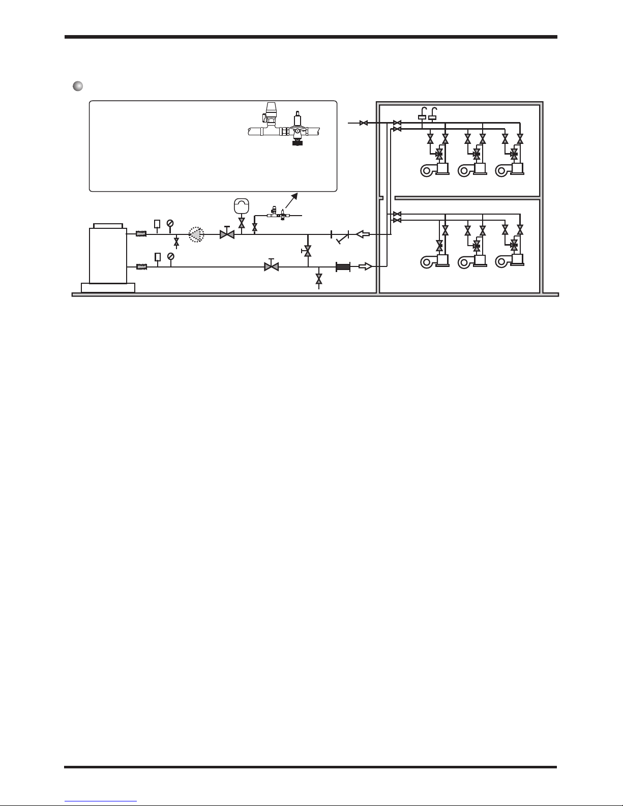
Especial installation( expandable water tank)
Appendix 1 Install sketch map
Appendix
Remark
1 main unit
2 fan coil
3 rubber flexible connection
4 thermometer
5 manometer
6 Y type filter
8 ball valve
10 bypass valve
1/2'
Technical request:
1.Each connection must be connected tightly and have no leakage.
2.the arrowhead orientation of automatic filled- water
must accord with water supply.
3.The pressure of automatic filled-water has been
set,and please do not remove screw.
autom ati c
fill- wat er
valve
Press ure
leaka ge
valve
2
14
15
13
17
Installation request:
1 The factory only offers main unit (1)in the legend, and the other modules
which are indispensable fittings, are provided by users or installation company.
2 The unit which of code contains the letter "B" ,has water pump inside and need
not install water pump outside (16)
3 Automatic ventilation(15)is installed on the top point of the water system。
4 The quantity proportion of two-way valve(13)and three-way valve(14)is
referred to the technical regulation, and there is three-way valve installed on the
farthest place of water system.
5 The ball valve (17) is used when it is swashed, filled water in the water system
and so on.
1
3
4
5
10
12
18
16
20
6
11
19
Conne ct supp ly pi pe
1/2'
inlet
outlet
8
11 drain valve
12 filter
13 two-way valve
14 three-way valve
15 automatic ventilation
16 water pump
17 ball valve
18 ball valve
19 expandable water tank
20 automatically filled-water
24
Appendix 2:
The installation explanation of automatic filled-water
Appendix
Page 27
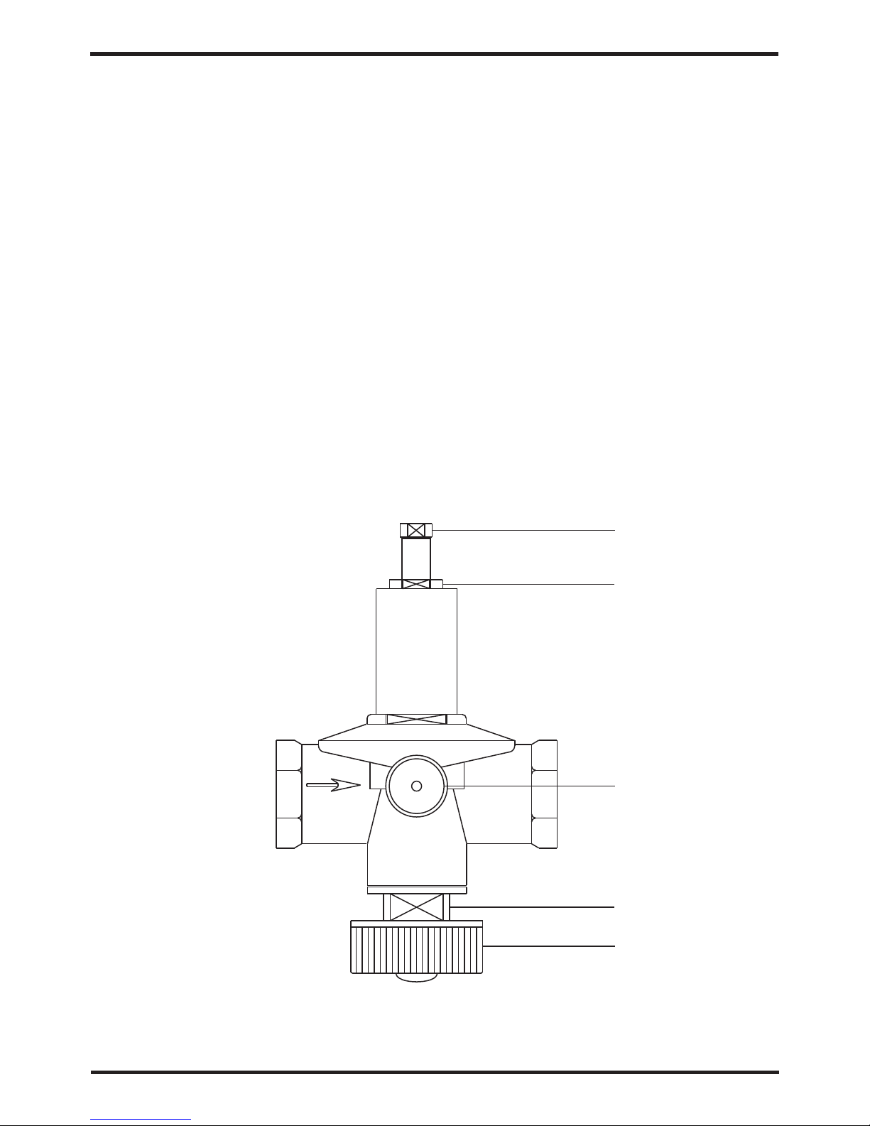
Appendix 2:
The installation explanation of automatic filled-water
1 When automatic filled-water valve is installed,the arrowhead orientation of inlet water must
accord with the orientation of valve ;
2 Automatic filled-water has been adjusted in advance to 1.5bar;
3 If readjust the pressure of inlet water,please operate as follows:
* open the screw cap(C);
* If reduce the pressure of water supply,pease unscrew the pressure to adjust the screw(B);
* If increese the pressure of waer supply,please screw down the pressure to adjust the screw (B)
4 When the system need fill water at first,wrest the handle(A) of filled-water.Then the handle(A)
can return(close) when the system is full of water.
5 Automatic filled-water Valve need clean in a periodic time and then you must close the tap,
unscrew the plug(D),remove the inside filter net.Please assemble them again after cleaning.
NOTICE:There are two connections for water pressure meter in the central section of
automatic filled-water,where the water pressure meter can be connected directly
and display the set pressure.The screw cap(C) must be tweaked after adjusting
the filled-water pressure.
B
C
1/4'
D
A
1/2'
Appendix
25
Page 28

Appendix 3:
The installation explanation of the leakage pressure valve.
1 The action pressure of leakage pressure valve 'is more than 3bar(valve is open),
but the pressure can not be adjusted.
2 The valve will open automatically to make sure that the water loop of air-con system
is safe when the water pressure in the backwater side is higher than t he set pressure.
Appendix
Appendix 4:
The way of assistant heat source connection
Unit provides the connection of assistant heat source which ca n not be only for gas-fired
boiler,but also for electronic boiler or wa rm-net pipe for city accordingly.
The way to the connection is as follows:
2)water chiller and heat pump+assistant el ectronic boiler
electro nic boile r
inlet
cable
water chiller and heat pump
gas-fir ed boiler
inlet
outlet
1)water chiller and heat pump+assistant gas-fired b oiler
Three -wa y val ve
control w ire
outle t
water chiller and heat pump
inlet
cable
outle t
inlet
outlet
outlet
inlet
26
Appendix
Appendix 5、
Note:
Connect frequency water pump
(PWM control) to reserved interface
as required and controller will be able
to automatically control water pump.
Page 29

Appendix
27
Appendix 5、
Ways of connection to remote controller
The following ways of connection to control system ar e optional based on user demand:
A. Simultaneously connect remote controller and n etworking interface:
PC8002
+12
NET
GND
Remote
controller
WiFi module
Note:
1、In the mode of unit operation, it is necessary to complet e value setting by remote controller.
2、It is advised to control equipment by mobile terminal a fter connection to WiFi module.
B. Connect with external water pump:
Note:
Connect frequency water pump
(PWM control) to reserved interface
as required and controller will be able
to automatically control water pump.
GND
Y 3
Frequency
water pump
Main controller
L
N
C. Connect to room temperature controller:
Note:
1、The way is applicable to special requireme nts of users;
2、Connect 485 signal wire to reserved termin al after determining the use of room
temperature controller.
R S4 8 5+
R S4 8 5-
PC8002
Room
temperature
controller
Page 30

Appendix 6、
Caution & Warning
1. The unit can only be repaired by qualified installer centre personnel or an au thorised
dealer.(for Europe market)
2. This appliance is not intended for use by persons (including children) with reduced physical
sensory or mental capabilities, or lack of experien ce and knowledge, unless they have been
given supervision or instruction concerning use of the appliance by a person responsible for
their safety. (for Europe market)
Children should be supervised to ensure that they do no t play with the appliance.
3. Please make sure that the unit and power connection have good earthing, otherwise may
cause electrical shock.
4. If the supply cord is damaged, it must be replaced by the manufactu rer or our service agent
or similarly qualified person in order to avoid a hazard.
5. Directive 2002/96/EC (WEEE):
The symbol depicting a crossed-out waste bin that is underneath the appliance indicates
that this product, at the end of its useful life, must be handled sepa rately from domestic
waste, must be taken to a recycling centre for electric and electr onic devices or handed
back to the dealer when purchasing an equivalent appliance.
6. Directive 2002/95/EC (RoHs): This product is compliant with directive 2002/95 /EC (RoHs)
concerning restrictions for the use of harmful substances in e lectric and electronic devices.
7. The unit CANNOT be installed near the flammable gas. Once there is any leakage of the gas
, fire can be occur.
8. Make sure that there is circuit breaker for the unit, lack of circu it breaker can lead to
electrical shock or fire.
9. The heat pump located inside the unit is equipped with an over-load protecti on system. It
does not allow for the unit to start for at least 3 minutes from a previous stoppage.
10. The unit can only be repaired by the qualified personnel of an installer cent er or an
authorized dealer. (for North America market)
11. Installation must be performed in accordance with the NEC/CEC by authorized perso n only.
(for North America market)
12. USE SUPPLY WIRES SUI TABLE FOR 75℃.
13. Caution: Single wall heat exchanger, no t suitable for potable water connection.
Appendix
28
When the unit will be installed at outdoor, ple ase use the cable which can against UV.
Appendix
1. Single phase unit
2. Three phase unit
Page 31
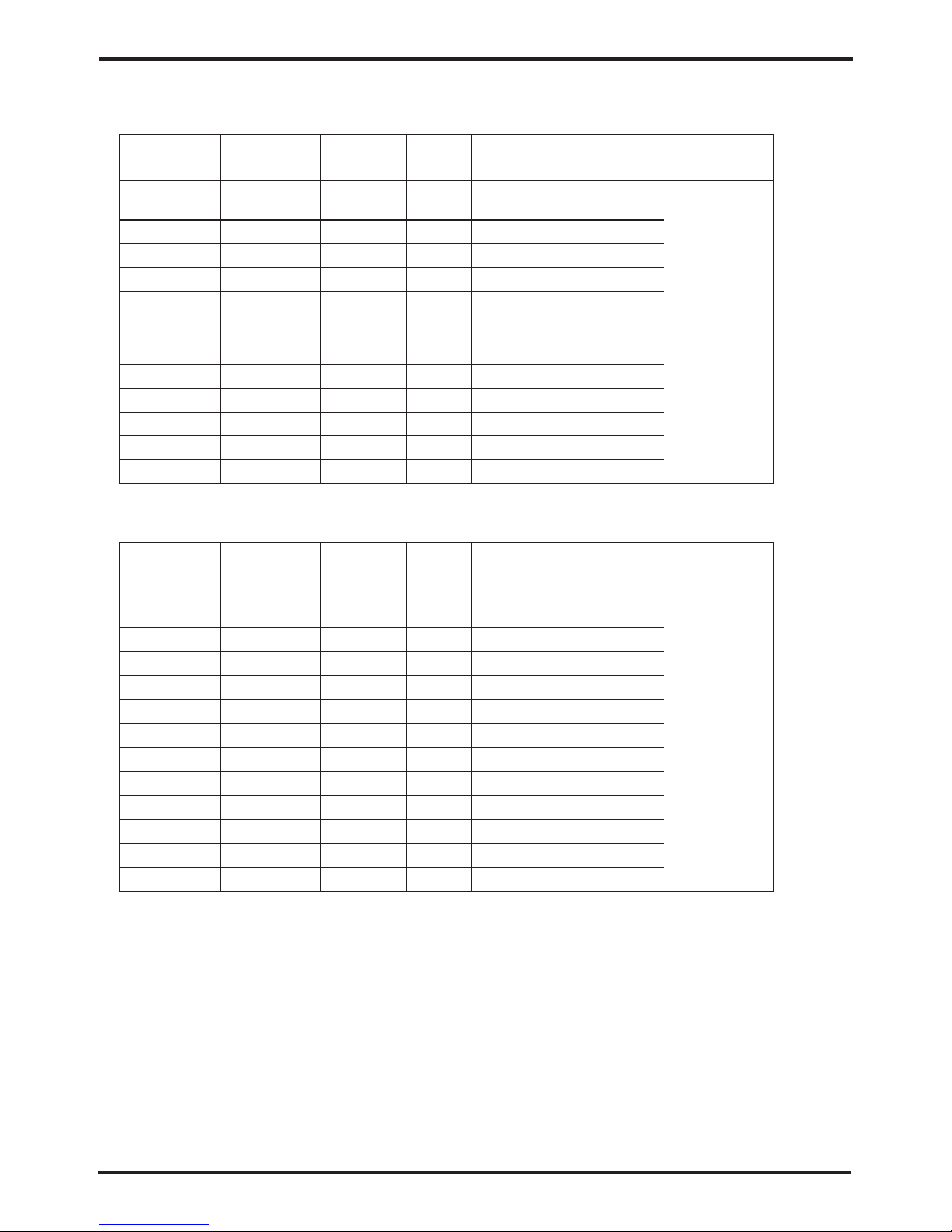
Appendix 7、Cable specification
When the unit will be installed at outdoor, ple ase use the cable which can against UV.
Appendix
29
1. Single phase unit
10~16A
16
~25A
25
~32A
32
~40A
40
~63A
63~75A
75~101A
101~123A
123~148A
148~186A
186~224A
Phase line
MCB
Creepage protector
Signal line
2
×
n 0 . 5 m m
Nameplate
maximum
current
Earth line
No more
than 10A
2
2×1.5mm
2
2×2.5mm
2
2×4mm
2
2×6mm
2
2×10mm
2
2×16mm
2
2×25mm
2
2×25mm
2
2×35mm
2
2×50mm
2
2×70mm
2
2×95mm
20A
32A
40A
40A
63A
80A
100A
125A
160A
225A
250A
280A
2
1.5mm
2
2.5mm
2
4mm
2
6mm
2
10mm
2
16mm
2
mm
25
2
mm
25
2
35mm
2
50mm
2
70mm
2
95mm
30mA less than 0.1 sec
10~16A
16
~25A
25
~32A
32
~40A
40
~63A
63~75A
75~101A
101~123A
123~148A
148~186A
186~224A
Phase line
MCB
Creepage protector
Signal line
2
×
n 0 . 5 m m
Nameplate
maximum
current
Earth line
No more
than 10A
20A
32A
40A
40A
63A
80A
100A
125A
160A
225A
250A
280A
2
1.5mm
2
2.5mm
2
4mm
2
6mm
2
10mm
2
16mm
2
mm
25
2
mm
25
2
35mm
2
50mm
2
70mm
2
95mm
2. Three phase unit
2
3×1.5mm
2
3×2.5mm
2
3×4mm
2
3×6mm
2
3×10mm
2
×
16mm
3
2
×
25mm
3
2
3×25mm
2
3×35mm
2
3×50mm
2
3×70mm
2
3×95mm
30mA less than 0.1 sec
30mA less than 0.1 sec
30mA less than 0.1 sec
30mA less than 0.1 sec
30mA less than 0.1 sec
30mA less than 0.1 sec
30mA less than 0.1 sec
30mA less than 0.1 sec
30mA less than 0.1 sec
30mA less than 0.1 sec
30mA less than 0.1 sec
30mA less than 0.1 sec
30mA less than 0.1 sec
30mA less than 0.1 sec
30mA less than 0.1 sec
30mA less than 0.1 sec
30mA less than 0.1 sec
30mA less than 0.1 sec
30mA less than 0.1 sec
30mA less than 0.1 sec
30mA less than 0.1 sec
30mA less than 0.1 sec
30mA less than 0.1 sec
Page 32

Code:20 160612- 0003
 Loading...