

evoheat Force 26-3, Force 26 Installation & Operation Manual


CONTENTS
1. Preface
2. Specifications
3. Installation and Connection
3.1 Installation of System
3.2 Swimming Pool Heat Pumps Location
3 .3 Location & minimum clearances
3.4 Swimming Pool Heat Pumps Plumbing
3.5 Swimming Pool Heat Pumps Electrical Wiring
3.6 Initial Start-up of the Unit
4. Usage and Operation
4.1 Function of the controller
4.2 Usage of the controller
4.3 Parameter table
5. Maintenance and Inspection
1
2
5
5
6
6
7
8
8
9
9
11
18
19
5.1 Maintenance
5.2 Trouble Shooting Guide
6. Appendix
7. warranty
8. warranty registration.................................................................................... 25
19
20
21
24

1. PREFACE
In order to provide our customers with quality, reliability and versatility, t his p rod uct h as
been made to str ict p rod uct ion s tan dar ds. T his m anu al in clu des a ll th e nec ess ary
info rmatio n abo ut in sta lla tio n, de bug gin g, di sch arg ing a nd ma int ena nce . Ple ase r ead t his
manual carefully before you open or maintain the u nit. The m anu fac tur e of th is pr odu ct wi ll
not be h eld responsible if someone is injured or the unit is damaged, as a result of
improper installation, debugging, or unnecessary maintenance. It i s vit al th at th e
instructio ns wi thi n thi s man ual a re ad her ed to a t all t ime s. Th e uni t mus t be installed by
qualified personnel.
The un it ca n onl y be re paired by qualified installer centr e , per son nel o r an au tho ris ed
dealer.
Maintenance and operation must be carried out according to th e recommended time and
freq uency, as s tat ed in this manual.
Use genuine standard spare parts only.
Fail ure to com ply w ith t hes e rec omm end ati ons w ill invalidate the wa rra nty.
Swimming Pool Heat Pump Unit heats th e swi mmi ng po ol water a nd ke eps the te mpe rat ure
constant. Fo r spl it ty pe un it, T he in doo r uni t can b e Dis cre tel y hid den o r sem i-h idd en to
suit a luxury house.
Our he at pu mp ha s fol low ing c haracteri sti cs:
1 Durable
The he at ex cha nge r is ma de of P VC & Tit ani um tu be wh ich c an wi ths tan d pro lon ged
exposure to swimming pool water.
2 Inst all ati on fl exi bil ity
The un it ca n be in sta lle d out doo rs or i ndo ors .
3 Quie t ope rat ion
The un it co mpr ise s an effi cie nt ro tar y/ sc rol l com pre sso r and a l ow- noi se fa n mot or,
which guarantees its q uie t ope rat ion .
4 Advanced controlling
The un it in clu des m icr o-c omp ute r con tro lli ng, a llo win g all o per ati on pa ram ete rs to b e
set. O per ati on st atu s can b e dis pla yed o n the L CD wi re co ntr oll er. Re mot e con tro lle r can b e
chosen as futu re op tio n.
1

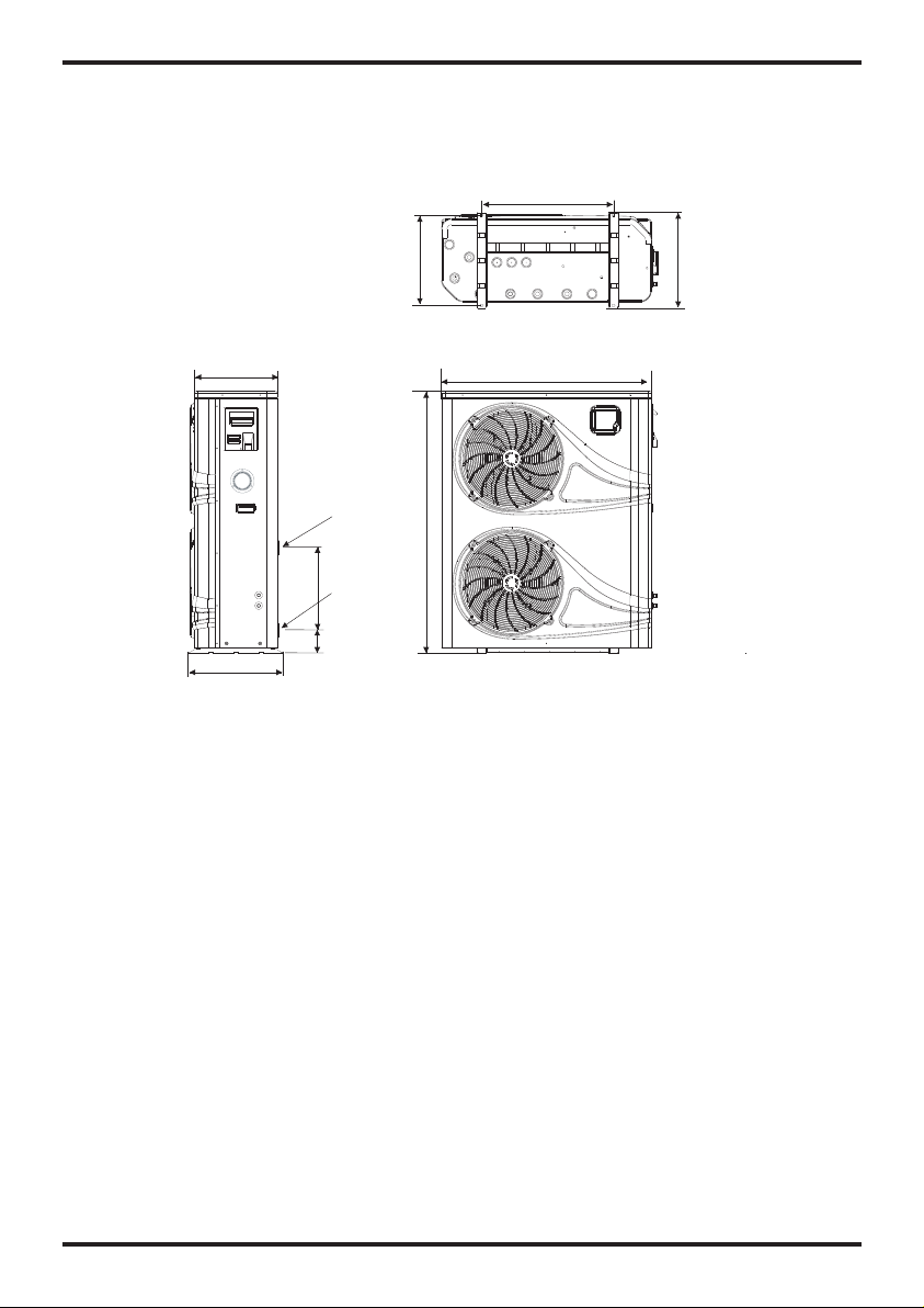
2.SPECIFICATION
2.2 Th e dime nsio ns for S wimm ing Po ol Hea t Pump U nit
Mode l:F orc e 26
630
unit:mm
395
455
Wat er O ut le t
Φ48.3
Wat er I nl et
440
Φ48.3
103
430
1003
1248
455
3
2.SPECIFICATION
Mode l:F orc e 26- 3
395
455
Wat er O ut le t
Φ48.3
Wat er I nl et
440
Φ48.3
103
unit:mm
630
430
1003
1248
455
4
3.INSTALLATION AND CONNECTION
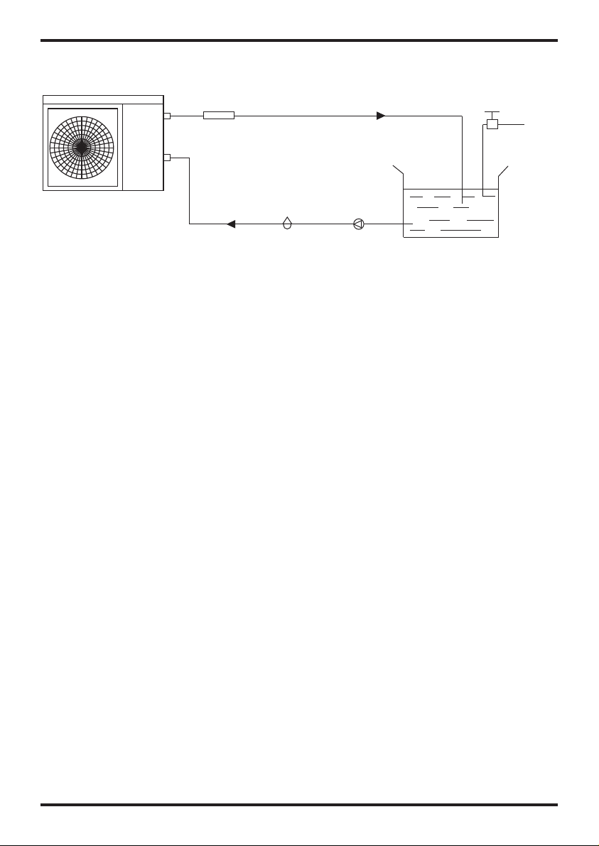
3.1 In sta lla tio n ill ust rat ion
Chlo rin ato r cel l
Wat er in let
Sand f ilt er
(or ot her t ype f ilt er)
Wat er ou tle t
Pool
Wat er pu mp
Valve
Wat er su ppl y
Insta llat ion it ems:
The fa cto ry on ly pr ovi des t he ma in un it an d the w ate r uni t; the other items in the illustration
are necessary spare parts for th e wat er sy ste m ,th at pr ovi ded b y use rs or t he in sta lle r.
Atten tion :
Please follow the se steps w hen using for t he fi rst t ime
1.Op en va lve a nd ch arge water.
2.Ma ke sure th at th e pum p and t he wa ter -in p ipe h ave b een fill ed wi th wa ter.
3.Cl ose the va lve a nd start t he un it.
ATTN: I t is ne ces sar y tha t the water-in pipe is hi ghe r tha n the pool surface.
The sc hemati c dia gram is fo r ref ere nce o nly. P lea se ch eck t he wa ter i nle t/outlet label on the
heat pump while plumbing installation.
5
3.INSTALLATION AND CONNECTION
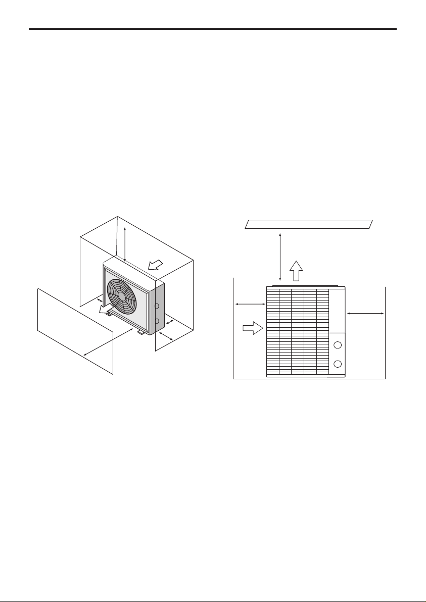
3.2 Swimming Pool Heat Pumps Location
Before installation it is very important to ensure 4 variables are carefully checked to allow
the unit to operate correctly:
• Adequate Air Flow
• Correct water flow volume
• Correct electrical connection & supply
• Heater condition
*For indoor pools please consult the supplier.
DO N
OT place the unit in an enclosed area, where the units discharge air can be
re-ci
rculated. In an enclosed area take measures to evacuate the cold waste air out
of the room. Conversely make sure there is adequate air entering the room to supply
the heat pump.
Air in let
500mm
700m m
Air ou tle t
2000mm
800mm
300mm
Air ou tle t
1000mm
0mm
250
3.3 Location & minimum clearances
Evo rec
ommend the heat pump should ONLY be installed in a location with appropriate ventilation. See
above for minimum airflow clearances.
The Evo pool heat pump should be installed with a minimum clearance of at least 3.5m to the water’s
edge. Furthermore, EvoHeat recommend installing the heat pump no greater than 7.5 meters away from
the water’s edge due to heat loss from the piping. If you do not have a location with these suggested
clearances, please contact our EvoHeat Tech Support Specialist on 1300 859 933 to discuss
appropriate installation locations.
The heat pump should be installed a maximum of 5m below the water level of the pool/spa.
Make sure the heat pump is not located where large amounts of water may run-off from a roof into the
unit. Sharp sloping roofs without gutters will allow excessive amounts of rain water mixed with debris
from the roof to be forced through the unit. A water deflector may be needed to protect the heat pump.
If installing the heater on an existing pump/filtration system the heater must be installed AFTER the
filter and BEFORE the chlorinator/sanitizer.
The heat pump should be installed on a flat level surface.In the event that a suitable location is
unavailable contact Evo Industries for specialist technical advice.
700m m
Air in let
3.INSTALLATION AND CONNECTION
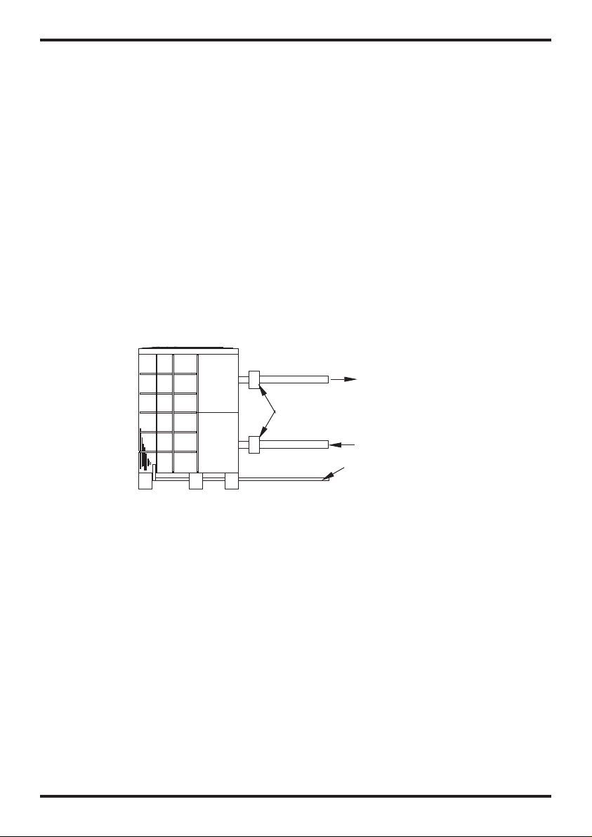
3.4 Swi mmin g Pool H eat Pu mps Pl umbi ng
The Sw imming Pool H eat Pump s exclusive rated flo w tit ani um he at ex cha nge r req uir es no
special plumbing arrangements except bypass(please set the flow rate according to the
nameplate). The w ate r pre ssu re dr op is l ess t han 1 0kP a at ma x. Fl ow ra te. S inc e the re is n o
residual heat or fl ame Temper atu res , Th e uni t doe s not n eed c opp er he at si nk pi pin g. PV C
pipe can be run straight into t he un it.
Location: Co nne ct th e uni t in th e poo l pum p dis cha rge (return ) line downstream of al l fil ter
and pool pumps, and upstream of any chl ori nators , ozo nat ors o r che mic al pu mps .
Stan dard model have slip glue fitti ngs w hich accept 32mm or 50 mm PVC pipe fo r
connection to the p ool o r spa f ilt rat ion p ipi ng. B y usi ng a 50 N B to 40 NB yo u can p lum b 40N B
Give s erious cons ideration to add ing a q uick cou pler fit tin g at th e uni t inl et an d out let t o all ow
easy draining of unit for winterizing and to provide easier access should servicing be
required.
To pool
PVC COUPL ER
RECOMME NDE D(P rov ide d)
From p ump
COND ENS ATION
DRAIN
BARB FTG
Condensation: Since the H eat pump c ool s down the a ir about 4 -5℃, wat er ma y con den se on
the fi ns of t he ho rse sho e sha ped evaporator. If the r ela tiv e hum idi ty is v ery h igh , thi s cou ld
be as mu ch as seve ral l itr es an h our. The wa ter w ill r un do wn th e fin s int o the b ase pan a nd
drain out through the barbed plastic con densation drain fit tin g on th e sid e of th e bas epa n.
This f itt ing i s des ign ed to a cce pt 20 mm cl ear v iny l tub ing w hic h can b e pus hed o n by ha nd
and run to a suita ble d rain. It i s eas y to mi sta ke th e con den sat ion f or a wa ter l eak i nsi de th e
unit.
NB: A quick way to verify that the wa ter i s con den sat ion i s to sh ut of f the unit and keep the
pool pump running. If the water st ops r unn ing o ut of t he ba sep an, i t is co nde nsa tio n. AN
EVEN QUIC KER WAY IS to TEST THE D RAI N WATER FOR CHLORINE - if the is no chlorine
present, the n it' s con den sat ion .
7
 Loading...