

Page 1

Page 2

CONTENTS
1. Preface
2. Specifications
3. Installation and Connection
3.1 Installation of System
3.2 Swimming Pool Heat Pumps Location
3 .3 Location & minimum clearances
3.4 Swimming Pool Heat Pumps Plumbing
3.5 Swimming Pool Heat Pumps Electrical Wiring
3.6 Initial Start-up of the Unit
4. Usage and Operation
4.1 Function of the controller
4.2 Usage of the controller
4.3 Parameter table
5. Maintenance and Inspection
1
2
5
5
6
6
7
8
8
9
9
11
18
19
5.1 Maintenance
5.2 Trouble Shooting Guide
6. Appendix
7. warranty
8. warranty registration.................................................................................... 25
19
20
21
24
Page 3

1. PREFACE
In order to provide our customers with quality, reliability and versatility, t his p rod uct h as
been made to str ict p rod uct ion s tan dar ds. T his m anu al in clu des a ll th e nec ess ary
info rmatio n abo ut in sta lla tio n, de bug gin g, di sch arg ing a nd ma int ena nce . Ple ase r ead t his
manual carefully before you open or maintain the u nit. The m anu fac tur e of th is pr odu ct wi ll
not be h eld responsible if someone is injured or the unit is damaged, as a result of
improper installation, debugging, or unnecessary maintenance. It i s vit al th at th e
instructio ns wi thi n thi s man ual a re ad her ed to a t all t ime s. Th e uni t mus t be installed by
qualified personnel.
The un it ca n onl y be re paired by qualified installer centr e , per son nel o r an au tho ris ed
dealer.
Maintenance and operation must be carried out according to th e recommended time and
freq uency, as s tat ed in this manual.
Use genuine standard spare parts only.
Fail ure to com ply w ith t hes e rec omm end ati ons w ill invalidate the wa rra nty.
Swimming Pool Heat Pump Unit heats th e swi mmi ng po ol water a nd ke eps the te mpe rat ure
constant. Fo r spl it ty pe un it, T he in doo r uni t can b e Dis cre tel y hid den o r sem i-h idd en to
suit a luxury house.
Our he at pu mp ha s fol low ing c haracteri sti cs:
1 Durable
The he at ex cha nge r is ma de of P VC & Tit ani um tu be wh ich c an wi ths tan d pro lon ged
exposure to swimming pool water.
2 Inst all ati on fl exi bil ity
The un it ca n be in sta lle d out doo rs or i ndo ors .
3 Quie t ope rat ion
The un it co mpr ise s an effi cie nt ro tar y/ sc rol l com pre sso r and a l ow- noi se fa n mot or,
which guarantees its q uie t ope rat ion .
4 Advanced controlling
The un it in clu des m icr o-c omp ute r con tro lli ng, a llo win g all o per ati on pa ram ete rs to b e
set. O per ati on st atu s can b e dis pla yed o n the L CD wi re co ntr oll er. Re mot e con tro lle r can b e
chosen as futu re op tio n.
1
Page 4

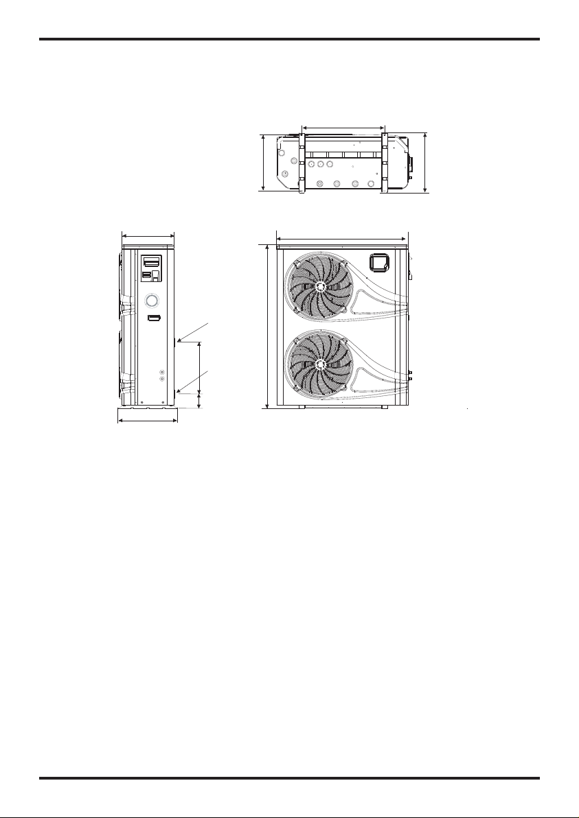
2.SPECIFICATION
2.2 Th e dime nsio ns for S wimm ing Po ol Hea t Pump U nit
Mode l:F orc e 26
630
unit:mm
395
455
Wat er O ut le t
Φ48.3
Wat er I nl et
440
Φ48.3
103
430
1003
1248
455
3
Page 5
2.SPECIFICATION
Mode l:F orc e 26- 3
395
455
Wat er O ut le t
Φ48.3
Wat er I nl et
440
Φ48.3
103
unit:mm
630
430
1003
1248
455
4
Page 6
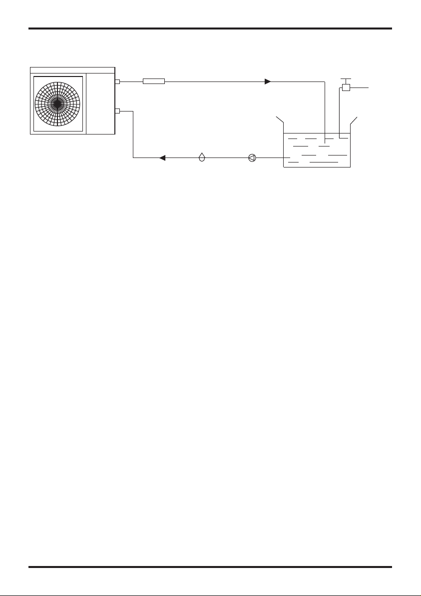
3.INSTALLATION AND CONNECTION
3.1 In sta lla tio n ill ust rat ion
Chlo rin ato r cel l
Wat er in let
Sand f ilt er
(or ot her t ype f ilt er)
Wat er ou tle t
Pool
Wat er pu mp
Valve
Wat er su ppl y
Insta llat ion it ems:
The fa cto ry on ly pr ovi des t he ma in un it an d the w ate r uni t; the other items in the illustration
are necessary spare parts for th e wat er sy ste m ,th at pr ovi ded b y use rs or t he in sta lle r.
Atten tion :
Please follow the se steps w hen using for t he fi rst t ime
1.Op en va lve a nd ch arge water.
2.Ma ke sure th at th e pum p and t he wa ter -in p ipe h ave b een fill ed wi th wa ter.
3.Cl ose the va lve a nd start t he un it.
ATTN: I t is ne ces sar y tha t the water-in pipe is hi ghe r tha n the pool surface.
The sc hemati c dia gram is fo r ref ere nce o nly. P lea se ch eck t he wa ter i nle t/outlet label on the
heat pump while plumbing installation.
5
Page 7
3.INSTALLATION AND CONNECTION
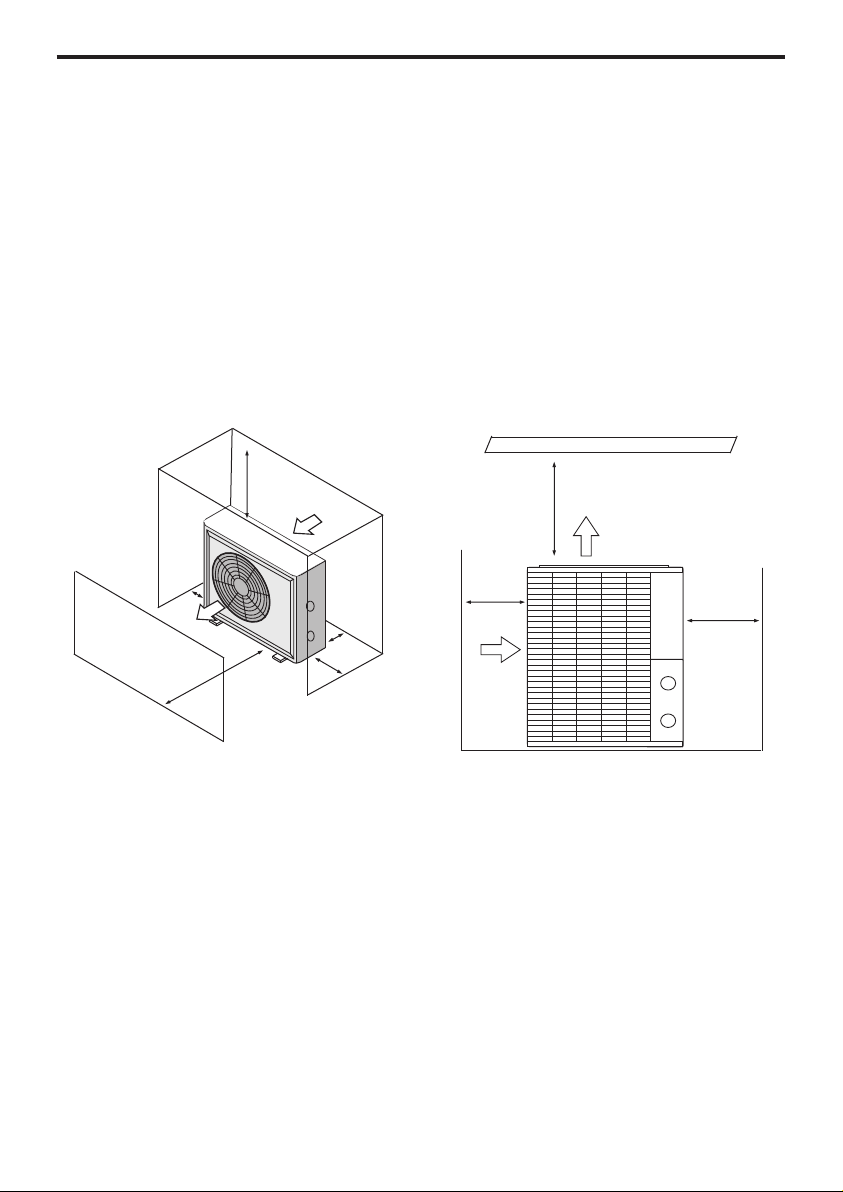
3.2 Swimming Pool Heat Pumps Location
Before installation it is very important to ensure 4 variables are carefully checked to allow
the unit to operate correctly:
• Adequate Air Flow
• Correct water flow volume
• Correct electrical connection & supply
• Heater condition
*For indoor pools please consult the supplier.
DO N
OT place the unit in an enclosed area, where the units discharge air can be
re-ci
rculated. In an enclosed area take measures to evacuate the cold waste air out
of the room. Conversely make sure there is adequate air entering the room to supply
the heat pump.
Air in let
500mm
700m m
Air ou tle t
2000mm
800mm
300mm
Air ou tle t
1000mm
0mm
250
3.3 Location & minimum clearances
Evo rec
ommend the heat pump should ONLY be installed in a location with appropriate ventilation. See
above for minimum airflow clearances.
The Evo pool heat pump should be installed with a minimum clearance of at least 3.5m to the water’s
edge. Furthermore, EvoHeat recommend installing the heat pump no greater than 7.5 meters away from
the water’s edge due to heat loss from the piping. If you do not have a location with these suggested
clearances, please contact our EvoHeat Tech Support Specialist on 1300 859 933 to discuss
appropriate installation locations.
The heat pump should be installed a maximum of 5m below the water level of the pool/spa.
Make sure the heat pump is not located where large amounts of water may run-off from a roof into the
unit. Sharp sloping roofs without gutters will allow excessive amounts of rain water mixed with debris
from the roof to be forced through the unit. A water deflector may be needed to protect the heat pump.
If installing the heater on an existing pump/filtration system the heater must be installed AFTER the
filter and BEFORE the chlorinator/sanitizer.
The heat pump should be installed on a flat level surface.In the event that a suitable location is
unavailable contact Evo Industries for specialist technical advice.
700m m
Air in let
Page 8
3.INSTALLATION AND CONNECTION
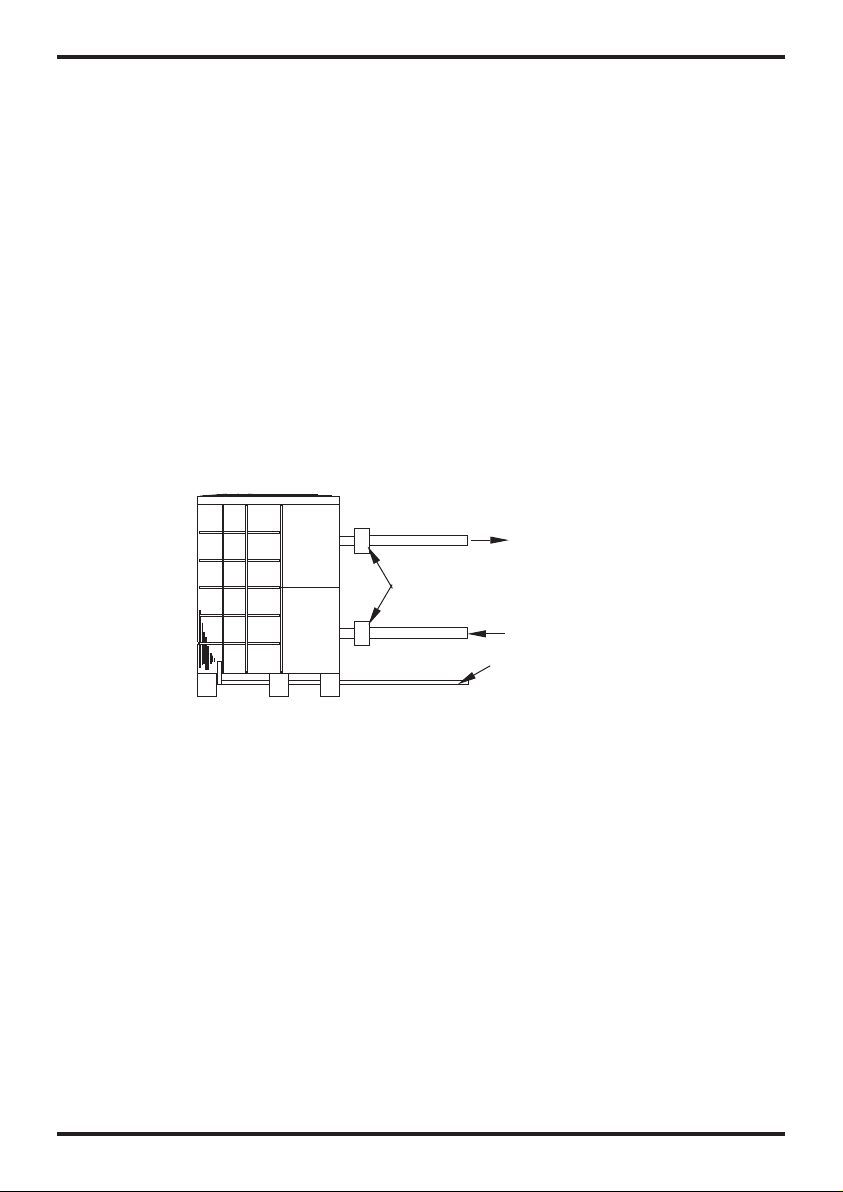
3.4 Swi mmin g Pool H eat Pu mps Pl umbi ng
The Sw imming Pool H eat Pump s exclusive rated flo w tit ani um he at ex cha nge r req uir es no
special plumbing arrangements except bypass(please set the flow rate according to the
nameplate). The w ate r pre ssu re dr op is l ess t han 1 0kP a at ma x. Fl ow ra te. S inc e the re is n o
residual heat or fl ame Temper atu res , Th e uni t doe s not n eed c opp er he at si nk pi pin g. PV C
pipe can be run straight into t he un it.
Location: Co nne ct th e uni t in th e poo l pum p dis cha rge (return ) line downstream of al l fil ter
and pool pumps, and upstream of any chl ori nators , ozo nat ors o r che mic al pu mps .
Stan dard model have slip glue fitti ngs w hich accept 32mm or 50 mm PVC pipe fo r
connection to the p ool o r spa f ilt rat ion p ipi ng. B y usi ng a 50 N B to 40 NB yo u can p lum b 40N B
Give s erious cons ideration to add ing a q uick cou pler fit tin g at th e uni t inl et an d out let t o all ow
easy draining of unit for winterizing and to provide easier access should servicing be
required.
To pool
PVC COUPL ER
RECOMME NDE D(P rov ide d)
From p ump
COND ENS ATION
DRAIN
BARB FTG
Condensation: Since the H eat pump c ool s down the a ir about 4 -5℃, wat er ma y con den se on
the fi ns of t he ho rse sho e sha ped evaporator. If the r ela tiv e hum idi ty is v ery h igh , thi s cou ld
be as mu ch as seve ral l itr es an h our. The wa ter w ill r un do wn th e fin s int o the b ase pan a nd
drain out through the barbed plastic con densation drain fit tin g on th e sid e of th e bas epa n.
This f itt ing i s des ign ed to a cce pt 20 mm cl ear v iny l tub ing w hic h can b e pus hed o n by ha nd
and run to a suita ble d rain. It i s eas y to mi sta ke th e con den sat ion f or a wa ter l eak i nsi de th e
unit.
NB: A quick way to verify that the wa ter i s con den sat ion i s to sh ut of f the unit and keep the
pool pump running. If the water st ops r unn ing o ut of t he ba sep an, i t is co nde nsa tio n. AN
EVEN QUIC KER WAY IS to TEST THE D RAI N WATER FOR CHLORINE - if the is no chlorine
present, the n it' s con den sat ion .
7
Page 9

3.INSTALLATION AND CONNECTION
3.5 Swi mming Pool Heat Pumps El ectr ical W irin g
NOTE : Alth oug h the u nit h eat e xch ang er is e lec tri cal ly is ola ted f rom t he re st of t he un it, i t
simply prevents the fl ow of e lec tri cit y to or f rom t he po ol wa ter. G rou ndi ng th e uni t is st ill
required to prote ct yo u aga inst sho rt ci rcu its i nsi de th e uni t. Bo ndi ng is a lso r equ ire d.
The un it ha s a sep ara te mo lde d-i n jun cti on bo x wit h a sta nda rd el ect ric al co ndu it ni ppl e
already in place. Just remove the screws and the fro nt pa nel , fee d you r sup ply l ine s in
thro ugh the co ndu it ni ppl e and wire-nut the electric sup ply w ires to th e thr ee co nne cti ons
already in the junction box (fou r con nec tio ns if t hre e pha se) . To comp let e ele ctr ica l hoo kup ,
connect Heat Pump b y electr ical conduit, UF c abl e or ot her s uit abl e mea ns as s pec ifi ed (a s
permitted by l oca l electr ical author iti es) t o a ded ica ted AC p ower sup ply b ranch circuit
equipped with the p roper ci rcuit br eak er, disconnect or time d elay fus e pro tec tio n.
Disconnect - A disconnect means (circuit breaker , fu sed or un-fused switc h) sh oul d be
located with in si ght of and r ead ily a cce ssible from the un it, T his i s com mon p rac tic e on
commercial and residential air conditioners and heat pumps. It prevents rem ote ly- ene rgi zing
unatten ded e qui pment an d permits tur nin g off p owe r at th e uni t whi le th e uni t is be ing
serviced.
3.6 Ini tial s tart up of th e Unit
NOTE - In or der f or th e uni t to he at th e poo l or sp a, th e fil ter p ump m ust b e run nin g to
circulate water t hro ugh t he he at ex cha nge r.
Star t up Pr oce dur e - Afte r ins tal lat ion i s com ple ted , you s hou ld fo llo w the se st eps :
1. Turn on your filter p ump. Che ck fo r wat er le aks a nd ve rify flo w to an d fro m the p ool .
2. Turn on the electri cal power supply to the u nit , the n pre ss th e key O N/O FF of w ire
controller, It sho uld s tar t in se ver al se con ds.
3. Afte r run nin g a few m inu tes m ake s ure t he ai r lea vin g the t op( sid e) of t he un it is
cooler(Between 5-10 ℃)
4. Wit h the u nit o per ati ng tu rn th e fil ter p ump o ff. The u nit s hou ld al so tu rn off au tom ati cal ly,
5. Allow the unit and po ol pump to r un 24 hours per day until desired pool water emperature is
reached. When the w ate r-i n tem per atu re re ach s ett ing , The u nit j ust s huts off. The un it wi ll
now automati cal ly re sta rt (a s lon g as yo ur po ol pu mp is r unn ing )wh en th e poo l tem per atu re
drops more tha n 2℃bel ow set tem peratu re.
Tim e Del ay- The unit is equipped with a 3 mi nut e bui lt- in so lid s tat e res tar t del ay in clu ded t o
protect cont rol c irc uit c omp one nts a nd to e lim ina te re sta rt cy cli ng an d con tac tor c hat ter.
This t ime d ela y wil l automa tic all y res tar t the u nit a ppr oxi mat ely 3 m inu tes a fte r eac h con tro l
circuit inte rru pti on. E ven a b rie f pow er in ter rup tio n wil l act iva te th e sol id st ate 3 m inu te
restart dela y and p revent the unit fr om st art ing u nti l the 5 m inu te co unt dow n is co mpl ete d.
Power interruptions during the delay period will have no effe ct on t he 3 mi nut e cou ntd own .
8
Page 10

4. USAGE AND OPERATION
9
Page 11

4. USAGE AND OPERATION
Page 12

4. USAGE AND OPERATION
11
Page 13

4. USAGE AND OPERATION
12
Page 14

4. USAGE AND OPERATION
13
Page 15

4. USAGE AND OPERATION
14
Page 16

4. USAGE AND OPERATION
15
Page 17

4. USAGE AND OPERATION
16
Page 18

4. USAGE AND OPERATION
17
Page 19

4. USAGE AND OPERATION
3. Para mete r tabl e
Meaning
Heating inlet tar get temp .
Cooling inlet target temp.
Auto i nlet tar get t emp .
Remark:
The wi re co ntr oll er ca n dis pla y the t emp era tur e uni t as "℉" or "℃" a cco rdi ng to t he un it
Mode l you bought.
27℃
27℃
27℃
Remar k Defau lt
Adjustable
Adjustable
Adjustable
18
Page 20

5. MAINTENANCE AND INSPECTION 5
5.1 Ma intena nce
Check the wate r sup ply d evi ce and the r ele ase ofte n. You should avoid the condition of no
wate r or air enteri ng into sy ste m, as t his w ill i nfl uen ce un it' s per for man ce an d rel iab ili ty.
You sh oul d cle ar th e poo l/s pa fi lte r reg ula rly t o avo id da mag e to th e uni t as a re sul t of th e
dirty of cl ogg ed fi lte r.
The ar ea around the u nit shou ld be dry, cl ean a nd we ll ve nti lat ed. C lea n the s ide h eat ing
exchanger regularly to maintain good heat exchange as conserve energy .
The op eratio n pre ssure of the refri ger ant syst em sh oul d onl y be se rvi ced b y a cer tif ied
tech nician .
Check the power sup ply and cable connection ofte n,. Sho uld t he un it be gin t o ope rat e
abnormally, swit ch it o ff a nd co nta ct th e qua lif ied t ech nic ian .
Discharge all water in the water pump and water syst em ,s o tha t fre ezi ng of t he wa ter i n the
pump or water sy ste m doe s not o ccu r. You should discharge the water at the botto m of
wate r pump if th e uni t wil l not b e use d for a n ext end ed pe rio d of ti me. You should check the
unit thoroughly and fi ll th e sys tem w ith w ate r ful ly be for e usi ng it f or th e fir st ti me af ter a
19
Page 21

5. MAINTENANCE AND INSPECTION
5.2 Trouble S hoo tin g Gui de
The co mmon fai lur e cause and solution.
20
Page 22

6.APPENDIX
1.Con nection of P CB ill ustr atio n
OUT1 OUT2
3
FUSE
4
T5AL 250 V
OUT 3
OUT 4
OUT 5
AC- N
CN1
CN2
PC1001
GND
12V
NET
Connections explanation:
Symbol
No.
1
2
3
4
5
6
7
8
9
10
11
12
13
14
15
16
17
18
19
20
21
22
23
24
OUT1
OUT2
OUT3
OUT4
OUT5
AC-N
NET GND 12 V
DI01 G ND
DI02 G ND
DI03 G ND
DI04 G ND
DI05 G ND
DI06 G ND
AI01 G ND
AI02 G ND
AI03 G ND
AI04 G ND
AI05 G ND
AI06 G ND
CN1
CN2
CN6
CN19
5V CN1 6 GN D
CN19
CN6
3
4
GND
DI0 1
GND
GND
DI0 2
DI0 3
GND
GND
DI0 4
DI0 5
CN4
GND
AI0 6
GND
AI0 5
GND
AI0 4
GND
AI0 3
GND
AI0 2
GND
AI0 1
+5V
CN1 6
GND
DI0 6
GND
CN3
Meaning
Compressor of sys tem 1(220 -23 0VAC)
Wat er pu mp(22 0-2 30VAC)
4way valve (220-230VAC)
High speed of fan motor(220-230VAC)
Low speed of fan moto r(220-230VAC)
Neutral wire
Wire c ontrol ler
On/O ff Sw itch(i npu t)(no us e)
Flow s witch (i npu t)( n orm al cl ose )
Low pressure protect
High pressure protect
No use
No use
Suction temp .(i npu t)
Wat er in t emp .(i npu t)
Wat er ou t tem p.( inp ut)
Temp. Of coil ( input)
Ambient temp.(i npu t)
Adjustable fan sp eed/Ex haust te mpe rature
Primary transfo rmer
Secondary transformer
With out u se
Electronic expansion valve
Flow m ete r
21
Page 23

6.APPENDIX
Cauti on & Warni ng
1. The u nit c an on ly be r epa ire d by qu ali fie d ins tal ler c ent re pe rso nne l or an a uth ori sed
deal er.(fo r Eur ope m ark et)
2. Thi s app lia nce i s not i nte nde d for u se by p ers ons ( inc lud ing c hil dre n) wi th re duc ed ph ysi cal
sens ory or men tal c apa bil iti es, o r lac k of ex per ien ce an d kno wledge, unl ess they h ave been
give n supervision or instruction concerning use of the appliance by a person responsible for
thei r saf ety. (for Europe market)
Chil dren should be supervised to ensure that they do not play with the a ppl ian ce.
3. Ple ase make sure that the un it an d pow er co nne cti on ha ve go od ea rth ing , oth erw ise m ay
caus e electr ica l shock.
4. If th e sup ply c ord i s dam age d, it m ust b e rep lac ed by t he ma nuf act ure r or ou r ser vic e age nt
or sim ila rly q ual ifi ed pe rson in order to avoid a hazard.
5. Dir ective 2 002 /96 /EC ( WEE E):
The sy mbol depicting a cros sed-out was te bi n tha t is un der nea th th e app lia nce i ndi cat es
that t his p rod uct , at th e end o f its u sef ul li fe, m ust b e han dle d sep ara tel y fro m dom est ic
wast e, mu st be t ake n to a re cyc lin g cen tre f or el ect ric a nd el ect ron ic de vic es or h and ed
back t o the d eal er wh en pu rch asing an equivalent appliance.
6. Dir ective 2 002 /95 /EC ( RoH s): T his p rod uct i s com pli ant w ith d ire cti ve 20 02/ 95/ EC (R oHs )
conc erning restrictio ns fo r the u se of h arm ful s ubs tan ces i n ele ctr ic an d ele ctr oni c dev ice s.
7. The u nit C ANN OT be ins tal led n ear t he fl amm abl e gas . Onc e the re is a ny le aka ge of t he ga s
, fire c an be o ccu r.
8. Mak e sure tha t the re is c irc uit b rea ker f or th e uni t, la ck of c irc uit b rea ker c an le ad to
elec tri cal s hoc k or fi re.
9. The h eat p ump l oca ted i nsi de th e uni t is eq uip ped w ith a n ove r-l oad p rot ect ion s yst em. I t
does n ot al low f or th e uni t to st art f or at l eas t 3 min ute s fro m a pre vio us st opp age .
10. Th e uni t can o nly b e rep air ed by t he qu ali fie d per son nel o f an in sta lle r cen ter o r an
auth ori zed d eal er. (fo r Nor th America market)
11. Ins tal lat ion m ust b e per for med i n acc ord anc e wit h the N EC/ CEC b y aut hor ize d per son o nly.
(for No rth America market)
12. US E SUP PLY WIRE S SUI TAB LE FO R 75℃.
13. Ca uti on: S ing le wa ll he at ex cha nge r, not suit abl e for p ota ble w ate r con nec tio n.
22
Page 24

6.APPENDIX
(2) Cable s peci fica tion
1. Single phase unit
Nameplate
maximum
current
No more
than 1 0A
10~16A
16
~25A
25
~32A
32
~40A
40
~63A
63~75A
75~101A
101~123A
123~148A
148~186A
186~224A
2. Three pha se unit
Nameplate
maximum
current
No more
than 1 0A
10~16A
16
~25A
25
~32A
32
~40A
40
~63A
63~75A
75~101A
101~123A
123~148A
148~186A
186~224A
Phase line
2×1.5m m
2×2.5m m
2×4mm
2×6mm
2×10mm
2×16mm
2×25mm
2×25mm
2×35mm
2×50mm
2×70mm
2×95mm
Phase line
3×1.5m m
3×2.5m m
3×4mm
3×6mm
3×10mm
×
16mm
3
×
25mm
3
3×25mm
3×35mm
3×50mm
3×70mm
3×95mm
2
2
2
2
2
2
2
2
2
2
2
2
2
2
2
2
2
2
2
2
2
2
2
2
Earth line
1.5m m
2.5m m
4mm
6mm
10mm
16mm
mm
25
mm
25
35mm
50mm
70mm
95mm
Earth line
1.5m m
2.5m m
2
4mm
2
6mm
10mm
16mm
mm
25
mm
25
35mm
50mm
70mm
95mm
Creepage protector
MCB
2
2
2
2
2
2
2
2
2
2
2
2
2
2
2
2
2
2
2
2
2
2
30mA less than 0.1 sec
20A
32A
30mA less than 0.1 sec
40A
30mA less than 0.1 sec
40A
30mA less than 0.1 sec
63A
30mA less than 0.1 sec
80A
30mA less than 0.1 sec
100A
30mA less than 0.1 sec
125A
30mA less than 0.1 sec
160A
30mA less than 0.1 sec
30mA less than 0.1 sec
225A
30mA less than 0.1 sec
250A
30mA less than 0.1 sec
280A
Creepage protector
MCB
30mA less than 0.1 sec
20A
30mA less than 0.1 sec
32A
30mA less than 0.1 sec
40A
30mA less than 0.1 sec
40A
30mA less than 0.1 sec
63A
80A
30mA less than 0.1 sec
100A
30mA less than 0.1 sec
30mA less than 0.1 sec
125A
30mA less than 0.1 sec
160A
225A
30mA less than 0.1 sec
30mA less than 0.1 sec
250A
30mA less than 0.1 sec
280A
Signal line
×
n 0.5mm
Signal line
×
n 0.5mm
2
2
When th e unit w ill be i nsta lled a t outd oor, pl ease u se the c able w hich c an aga inst UV.
23
Page 25

EVOHEAT Pump Warranty
1. The titanium heat exchanger tubing is guaranteed against corrosion for a period of twenty five
(25) years from the date of purchase when used with chlorine, salt, bromine or sea water. (*25 year
warranty on the titanium heat exchanger is valid for Evo heat pumps purchased post 15.05.2018. If
purchased prior please refer to your original operating manual for warranty details).
2. The compressor is guaranteed for five (5) years from the date of purchase.
3. All other parts are guaranteed for two (2) years from the date of purchase.
4. This warranty covers all labour for twelve (12) months from the date of purchase.
5. This warranty excludes any defect or injury caused by or resulting from misuse, abuse, neglect,
accidental damage, improper voltage, vermin infestation, incompetent installation, any fault not
attributable to faulty manufacture or parts, any modifications which affect the reliability or
performance of the unit.
6. This warranty does not cover the following:
a. Natural Disasters (hail, lightening, flood, fire etc.)
b. Rust or damage to paintwork caused by a corrosive atmosphere
c. When serviced by an unauthorized person without the permission of Evo Industries
d. When a unit is installed by an unqualified person
e. Where a unit is incorrectly installed
f. When failure occurs due to improper or faulty installation
g. Failure due to improper maintenance (refer Operating Instructions)
h. ‘No Fault Found’ service calls where the perceived problem is explained within the
Operation Instructions
i. Costs associated with delivery, handling, freighting, or damage to the product in transit.
7. If warranty service is required you should:
a. contact Evo Industries Australia on 1300 85 99 33 or via our Contact page on our web
site
b. provide a copy of your receipt as proof of purchase
c. have completed the online warranty registration or provide a completed warranty card.
8. Home service is available within the normal operating area of your Evo Industries authorized
Service Centre. Service outside this area will incur a traveling fee. Unless otherwise specified to the
purchaser, the benefits conferred by this express warranty and additional to all other conditions,
warranties, rights and remedies expressed or implied by the Trade Practices Act 1974 and similar
consumer protection provisions contained in legislation of the States and Territories and all other
obligations and liabilities on the part of the manufacturer or supplier and nothing contained herein
shall restrict or modify such rights, remedies, obligations or liabilities
24
Page 26

Warranty Registration
To register your Warranty, please enter the following details or go online at https://evoheat.com.au/warrantyregistration/ to register directly at our website.
Fields with a star (*) must be filled in. For information about what Evo Industries Australia will do with your
personal details, please refer to our Privacy Disclaimer on our website.
Family Name: * ___________________________________________________________________
Given Name: * ___________________________________________________________________
Preferred Title: *___________________________________________________________________
Age Group: * 18-24 25-34 35-44 45-54 55-64 64+
Street Address: * ___________________________________________________________________
Suburb: * ________________________________________________________________________
Postcode: * _______________________________________________________________________
State: * _________________________________________________________________________
Email: * _________________________________________________________________________
Please tell us about which EvoHeat product you bought, who you bought it from and what you will be using it
for.
Product & Model: *_________________________________________________________________
Serial Number:* ____________________________________________________________________
Authorised Installer:* _______________________________________________________________
Date Purchased: *__________________________________________________________________
Date Installed:* ____________________________________________________________________
Receipt Number: *_________________________________________________________________
Company you bought it from: *_______________________________________________________
Did you purchase the item when you purchased your pool?: ________________________________
If you purchased it after the pool, how many years did you wait?: ____________________________
What size is your pool or spa?: ________________________________________________________
Why did you choose an EVOHEAT product? ____________________________________________
Code:20151021-0003
 Loading...