

Page 1

Inverter Air Source Water Heat Pump
Installation and Instruction Manual
Page 2

CONTENT
1 Preface
2 Safety Precaution
(1) Mark not es
(2) Icon Not es
(3) Warning
(4) Attenti on
3 Specification
(1) Appeara nce a nd structure of the heat pump
(2) Th e data of unit
(3
) Unit dimen sio n
4 Installation
(1) Applica tio n of heat pump
) Choose a rig ht he at pump unit
(2
(3
) Installa tio n place
(4) Instal lat ion method
(5
) Water loop connectio n
) Power supp ly co nnection
(6
(7
) Location o f the u nit
(8) Transit
(9) Trial Run nin g
5 Use and Operation Instruction of Wire Controller
(1)Main in ter fac e display and function
(2) On and off
(3) Mode switc h
(4) Setting of t arg et te mperature
(5) Temp erature setting
(6) Fast heating
(7) Timer set tin g
(8) Setup in ter fac e
(9) Th e operation of time setting
6 Form of Troubleshooting
(1) Make jud gme nt and troubleshooting
7 Appendix
(1) Appendi x 1
) Appendix 2
(2
(3
) Appendix 3
(4
) Appendix 4
) Appendix 5
(5
) Appendix 6
(6
1
2
2
2
3
4
5
5
6
7
9
9
10
10
10
11
11
11
12
12
13
13
15
15
16
17
18
18
19
20
27
27
28
28
29
30
30
31
32
Page 3

Preface
In order to provide our customers with high quality, strong, reliable and versatile products, this
heat pump is produced by strict design and manufacture standards.
This m anual inc ludes all t he necess ary inf or matio n ab out ins ta llati on , debug gi ng,
disc harging a nd mainte nance. Pl ease re ad t his man ua l caref ul ly befo re y ou open o r
maintain the unit.
The manufacturer of this product will not be held responsible if someone is injured or
the unit is damaged as a result of improper installation, debugging, unnecessary maintenance
which is not in line with this manual.
The un it must be in stalled b y qualifi ed pers on nel.
It is vi ta l that th e below ins tructio ns are adhe red to at a ll t imes to k ee p the war ra nty.
—
The un it can only b e opened or r epaired b y quali fi ed inst al ler or an a ut horis ed d ealer.
—Main tenance a nd operat ion must be c arrie d ou t accor di ng to the r ec ommen de d time an d
freq uency, as stat ed i n this ma nu al.
—Use ge nuine sta ndard spa re parts on ly.
Failure to comply with these recommendations will invalidate the warranty.
The Evo Flex is a high efficiency, energy saving and environmentally friendly equipment, which is
mainly used for house warming. It can work with any kind of indoor unit such fan coil, radiator, or
floor heating pipe, by providing warm or hot water. One unit of monobloc heat pump can also work
with several indoor units.
The Evo Flex is designed to have heat recovery by using a super heater which can provide hot
water for sanitary purposes.
This series of heat pump unit has the following features:
1 Advan ced contr olling
The PC microcomputer based controller is available for the users to review or set the running
parameters of the heat pump. Centralized controlling systems can control several units by PC.
2
Neat Appearance
The heat pump is designed to look neat and subtle. The monobloc one has the water
pump i ncluded w hich is ver y easy for in stallat ion.
3 Flexible installation
The unit has a smart structure with compact body, just a simple outdoor installation is needed.
4 Quiet running
High quality and efficient compressor, fan and water pump is used to ensure low noise level with
insulation.
5 Good heat exchange rate
The heat pump unit uses a specially designed heat exchanger to enhance whole efficiency.
6 Larg e working r ange
This ser ie s of heat p um p is desi gn ed to wor k under diffe re nt work in g condi tions as lo w
as -15 d egrees fo r heating .
1
Page 4
Safety Precaution
To prevent the users and others from the harm of this unit, and avoid
damage on the unit or other property by using the heat pump properly.
Please read this manual carefully and understand the following information
correctly.
Mark Notes
Mark
WARNING
ATTENTION
Icon notes
Icon
Meaning
A wrong o peratio n may lead to d eath or hea vy inju ry o n
peop le.
A wrong o peratio n may lead to h arm on peop le or los s of
mate rial.
Meaning
Proh ibition . What is pro hibited w ill be ne ar by this i co n
Comp ulsory im plement . Th e listed ac tion need t o be taken.
ATTEN TI ON ( inclu de WA R NI NG )
Plea se pay atte ntion to wh at is indic ated.
2
Page 5
Safety Precaution
安装前注意事项
Warning
Installation
Prof essiona l install er
is req uired.
Eart hing is req uired
Operation
PROHIBITION
Shut off the power
Meaning
The he at pump mus t be instal led by qual ified p er sonal s,
to avo id improp er instal lation wh ich can l ea d to wate r
leak age, elec trical sh ock or fire .
Please make sure that the unit and power connection have
good earthing, otherwise it may cause electrical shock.
Meaning
DO NOT put fingers and hands into the fans and evaporator of
the unit, otherwise it may cause injury.
When there is something wrong or a strange smell, the power
supply needs to be shut off to stop the unit. Continuing to run
may cause electrical shortage or fire.
Move and repair
Entrust
Entrust
Prohibit
Meaning
When the heat pump needs to be moved or installed again,
plea se entrus t dealer or q ualifie d perso n to c arry it o ut .
Impr oper inst allatio n will lead t o water lea kage, e le ctric al
shoc k, injury o r fire.
It is prohibited to repair the unit by the user himself,
otherwise electrical shock or fire may occur.
When the heat pump needs to be repaired, please entrust
dealer or qualified person to carry it out. Improper movement or
repair on the unit will lead to water leakage, electrical shock,
injury or fire.
3
Page 6
Safety Precaution
安装前注意事项
ATTENTION
Installation
Inst allatio n Place
Fix th e unit
Need
circ uit break er
Operation
Chec k the
inst allatio n basemen t
Meaning
The unit CANNOT be installed near flammable gas. Once
there is any leakage of the gas, fire can be occur.
Make sure that the basement of the heat pump is strong
enough to avoid the unit moving or falling.
Make sure that there is circuit breaker for the unit, lack of
circuit breaker can lead to electrical shock or fire.
Meaning
Please check the installation basement in a timely period
(
monthly), to avoid any decline or damage on the base which
may hurt people or damage the unit
Swit ch off
the po wer
Proh ibition
Proh ibition
Please switch off the power for cleaning or maintenance.
It is prohibited to use copper or iron as a fuse. The right fuse
must be fixed by
It is pr ohibite d to spray th e flammab le gas to the h eat pum p,
as it ma y cause fir e.
an electrician for the heat pump.
4
Page 7
Specification
1. Appearance and Structure of the heat pump
Evo Flex 10
Air ou tlet in h orizo ntal
dire ction
Evo Flex 17 & 25
The lo ngest d istan ce of ins talli ng the
remo te cont rolle r is 200 me ters.
Wat er outl et tube
Wat er intl et tube
Remo te Cont rolle r
(Man ually )
Remo te Contro ller
(Man ually)
Air ou tlet in hor izontal
dire ction
The lo ngest dis tance of in stallin g the
remo te contro ller is 200 m eters.
Wat er outlet t ube
Wat er intlet t ube
5
Page 8
Specification
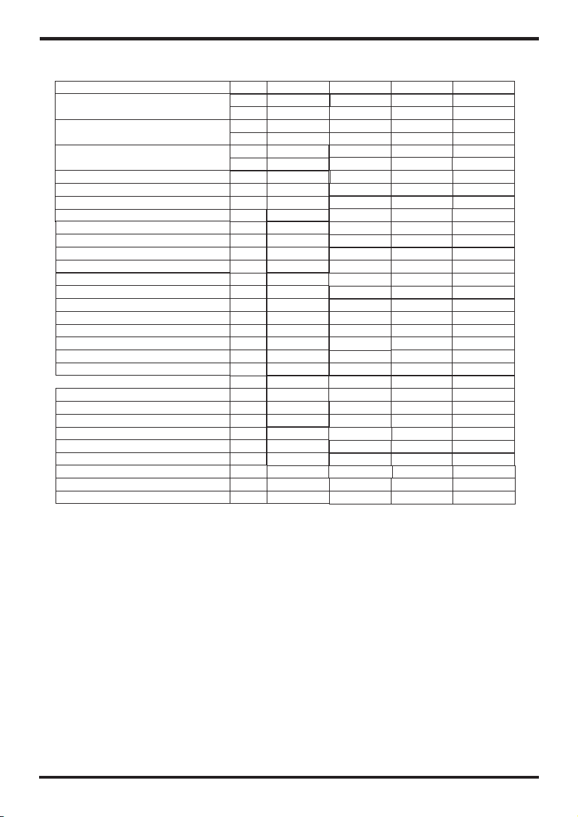
2. The data of unit
Model
Cooli ng C ap ac it y
Heati ng C ap ac it y
Hot Wat er C ap ac it y
Cooli ng P ow er I np ut
Heati ng P ow er I np ut
Hot Wat er P ow er I np ut
Opera ti on E le ct ric Cur re nt (m ax)
Cooli ng C ap ac it y Range
Heati ng C ap ac it y Range
Hot Wat er C ap ac it y Range
Cooli ng P ow er I np ut Rang e
Heati ng P ow er I np ut Rang e
Hot Wat er P ow er I np ut Rang e
Power S up pl y
Compr es so r Qu an tity
Compr es so r Mo de
Fan Qua nt it y
Fan Pow er I np ut
Fan Rot at e Sp ee d
Noise
Water P um p In pu t
water h ea d
Water C on ne ct io n
Water F lo w Vo lu me
Water P re ss ur e Dr op(ma x)
Unit Ne t Di me ns io ns (L/W /H )
Unit Sh ip pi ng D im ensio ns ( L/ W/ H)
Net Wei gh
Shipp in g We ig ht
l
t
Evo Flex
kW
BTU/h
kW
BTU/h
kW
BTU/h
kW
kW
kW
A
kW
kW
kW
kW
kW
kW
W
RPM
dB(A)
kW
m
inch
3
m /h
kpa
mm
mm
kg
kg
10
10
34121
11.5
39240
13.2
45040
3.4
3.4
3.6
15.7
2.0~10
2.5~11.5
4.2~13.2
1.0~3.4
0.8~3.4
1.0~3.6
230V~/50Hz
1
Rotary
1
75
850
54
0.18
12.5
1
1.6
24
953*445*910
1040*490*920
See nameplate
See p ackag e label
17
14.5
49489
16.5
56315
21.6
73702
5.6
5.1
6.2
27
5.0~14.5
5.0~16.5
7.4~21.6
1.6~5.6
1.2~5.1
1.5~6.2
230V~/50Hz
1
Rotary
2
75×2
850
58
0.5
21
1 1/4
2.8
105
996*395*1320
1070*435*1340
See nameplate
See p ackag e label
25
20
68260
25
85325
30
102364
9.0
9.0
8.2
14.0
7.0~20.0
8.0~25.0
11.0 ~3 0. 0
2.5~9.0
2.5~9.0
2.1~8.2
380V/3N~/50Hz
1
Rotary
2
150×2
900
62
0.65
22.5
1 1/4
4.2
71
1175 *4 00*1592
1225*430*1600
See nameplate
See p ackag e label
Cool ing worki ng condit ion:(DB /WB)3 5℃/2 4℃, (Outl et /Inle t) 7℃/ 12℃.
Heat ing worki ng condit ion: (DB/ WB) 7℃/6℃. (Out let/Inl et) 35℃/3 0℃.
Hot Water work ing con di tion: ( DB /WB) 20℃/ 15℃. ( Outle t/ Inlet ) 40℃/ 45℃.
BS EN 14 511-1 -2013 Ai r co nditi oner, whol e liquid co oling mac hine, e le ctric c om press or.
Part 2: Tes t co nditi on P art3: Test m ethod P ar t4:re lated req uiremen ts.
6
Page 9
Specification
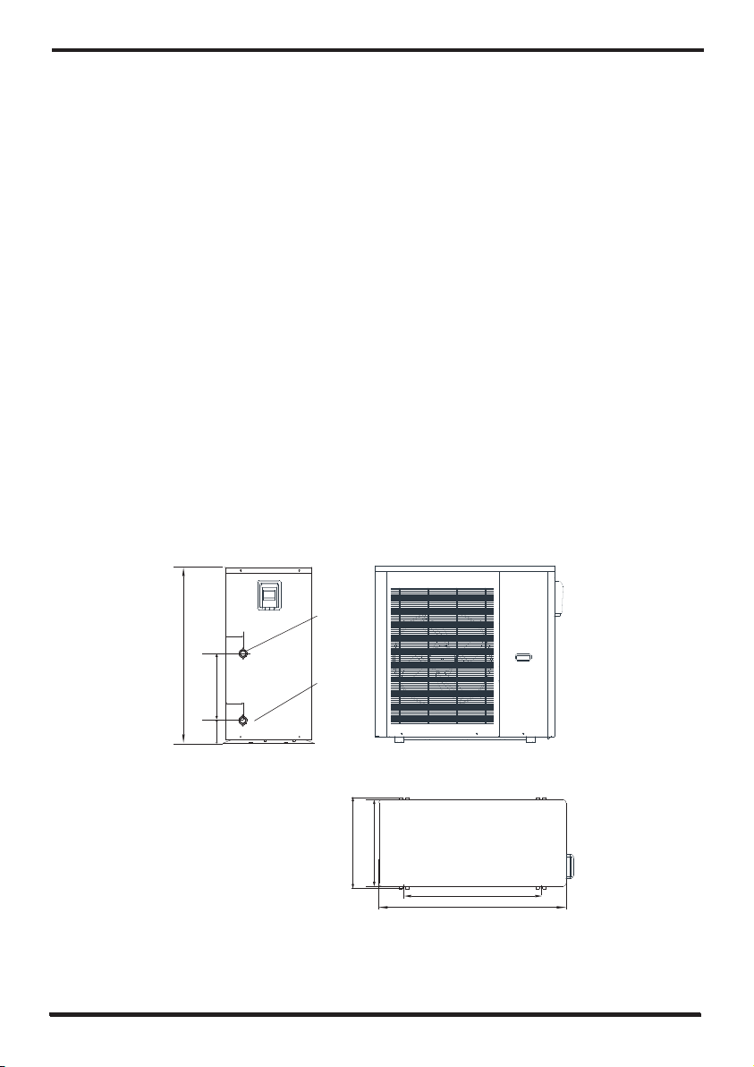
3. Unit dimension
Evo Flex 10
910
338
132
80
80
Wate r outle t 1
Wate r inlet 1
465
445
700
953
7
Page 10
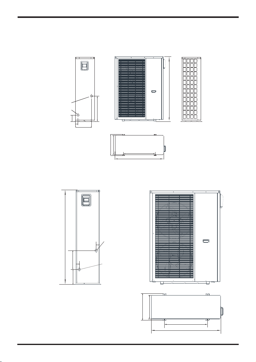
Specification
Evo Flex 17
Wat er outl et 1 1/4' '
Wat er inlet 1 1 /4''
Evo Flex 25
133
1320
525
55
330
395
437
650
996
159 2
320
254
Wate r outle t 1 1/4''
55
55
Wate r inlet 1 1 /4''
450
400
725
117 5
8
Page 11

Installation
Unit fe atures
1. Plate heat exchanger
Use the SWEP efficient heat exchanger with small size and high efficiency.
2. Environmentally friendly refrigerant
Using the new generation of environmentally friendly refrigerant R410, which is harmless to the
ozone sphere.
3. Heating in frigid environment.
Optimized designed unit can achieve the heating function normally even when the ambient
temperature is -15℃.
4. Spraying condensation
The water-cooling system will be opened automatically to guarantee the normal operation of
cooling when the ambient temperature is higher than 30℃.
1 Application of heat pump
1.1 Only for air-con
CONNECTING HOSE
GENE RAL VALVE
WATER PUMP
NON-RETURN VALVE
TEMPERATURE METER
THREE-WAY VALVE
EXPANSION TANK
PRESSURE DIFFERENTIAL
BYPASS VALVE
AUTOMATIC REFILL VALVE
out let
inl et
Y-TY PE FILTER
PRES SURE METE R
VENT VALVE
SAFE TY VALVE
1/2'
9
Page 12

Installation
2 Choosing the right unit
2.1 Based on the local climate condition, construction features and insulation level,
calculate the required cooling(heating) capacity per square meter.
2.2 Co nclude th e total cap acity whi ch will b e ne eded by t he c onstr uc tion.
2.3 Acc ording to t he total ca pacity ne eded, c ho ose the r ig ht mode l by c onsul ti ng the he at.
pump f ea tures a s below:
Heat p um p featu res
Cool ing only un it: chille d water out let tem p. a t 5-15 , m ax imum am bi ent tem p. a t 43 .
Heat in g and Coo ling unit: f or coolin g chill ed w ater ou tl et temp . at 5 -15 ,max imum
ambi ent temp. a t 43 . For hea ting, war m water inl et temp . at 4 0-50 , m in imum am bi ent
temp . at - 10 .
Unit a pplicat ion
Evo Flex is used for house, office, hotel,s and so forth which need heating or
cooling separately, with each individual area needing to be controlled.
℃
℃ ℃
3 Installation place
The unit c an b e insta ll ed on any p lace outd oor which c an carry he avy mac hi ne such
as ter ra ce, hou setop, gr ound and so o n.
The location must have good ventilation.
The place is free from heat radiation and other fire flame.
A Some sort of cover is needed in winter to protect the heat pump from snow.
Ther e must be not o bstacle s near the ai r inlet a nd o utlet o f th e heat pu mp .
A place w hich is fre e from stro ng air blow ing.
Ther e must be wat er channe l around th e heat pu mp t o drain t he c onden si ng wate r .
Ther e must be eno ugh space a round the u nit for m ai ntena nc e.
℃ ℃
℃
4 Installation method
The heat p um p can be in st alled o nto the con crete bas ement by ex pansi on s crews , or
onto a s teel fram e with rubb er feet whi ch can be p la ced on th e gr ound or h ou setop .
Make s ure that th e unit is pla ced horiz ontal ly.
10
Page 13

Installation
5 Water loop connection
Plea se pay atte ntion to be low matte rs when t he w ater pi pe i s conne ct ed:
Try to reduce the resistance to the water from the piping.
The piping must be clear and free from dirt and blockage. Water leakage test must be carried
out to ensure there is no water leaking. And then the insulation can be made. Attention that the
pipe must be tested by pressure separately. DO NOT test it together with the heat pump.
There must be an expansion tank on the top point of the water loop, and the water level in the
tank must be at least 0.5 meter higher than the top point of the water loop.
The flow switch is installed inside of the heat pump, check to ensure that the wiring and action
of the switch is normal and controlled by the controller.
Try to avoid air staying inside of the water pipe, and there must be air vent on the top point of
the water loop.
There must be thermometer and pressure meter at the water inlet and outlet, for easy
inspection during running.
6 Power supply connection
Open t he front pa nel, and op en the powe r suppl y ac cess.
The po wer suppl y must go thr ough the wi re acce ss a nd be con ne cted to t he p ower
supp ly termin als in the co ntrolli ng box. Then co nnect the 3 -sign al w ire plu gs o f the
wire c ontroll er and main c ontroll er.
If the o utside wa ter pump is n eeded, pl ease in se rt the po we r suppl y wi re into t he w ire
acce ss also and c onnect to t he water pu mp term in als.
If an ad ditiona l auxilia ry heater i s need to b e co ntrol le d by the he at p ump con tr oller,
the re lay (or pow er) of the au x-heate r must be c on necte d to t he rele va nt outp ut o f
the co ntrolle r.
7 Location of the unit
。
A
Barrier
Air In let
The picture shows the location of horizont al air outl et unit.
B
!
Requ irement s
A>500mm; B>1500mm;
C>1000mm;D>500mm
The mi nimum ven tilatio n distanc e in diag ra m 1.
Barrier
Air Outle t
Attention
11
Main tenance
Spac e
C
Barrier
D
Barrier
Page 14

Installation
8 Transit
When the unit needs to be hung up during installation, an 8
meters cable is needed, and there must be soft material
betw een the cab le and the un it to preve nt dama ge t o
the he at pump cab inet. (Se e picture 1 )
Pict ure 1
WARNING
DO NOT touch the heat exc han ger of the heat pum p wit h fin gers or other obj ect s!
9 Trial Running
Insp ection be fore tria l running
Chec k the indoo r unit, and m ake sure th at the pipe c onnec ti on is rig ht a nd the re le vant
valves are open .
Check the water loop, to ensure that the water inside of the expansion tank is full enough, the
water supply is working wel, the water loop is full of water and without any air. Also make sure
there is good insulation for the water pipe.
Chec k the elect rical wir ing. Make s ure tha t th e power v ol tage is n or mal, th e sc rews ar e
fast ened, the w iring is ma de in line wi th the di ag ram, an d th e earth in g is conn ec ted.
Chec k the heat pu mp unit inc luding al l of the sc re ws and pa rt s of the he at p ump to se e if
they a re in good or der. When po wer on, rev iew the i nd icato r on t he cont ro ller to s ee i f
ther e is any fail ure indic ation. The ga s gauge can b e connect ed to the che ck valv e to
see th e high pres sure(or l ow pressu re) of the sy stem du ri ng tria l ru nning .
Trial run ning
Star t th e heat pu mp by press " " k ey on the con troller. C heck whet her the w at er pump i s
runn ing, if it ru ns normal ly there wi ll be 0.2 MPa o n the wat er p ressu re m eter.
When t he water pu mp runs for 1 m inutes, t he compre ssor wi ll s tart. H ea r wheth er t here is
stra nge sound f rom the com pressor. I f abnorma l sound o cc urs ple as e stop th e un it and
chec k the compr essor. If th e compres sor runs we ll plea se l ook for t he p ressu re m eter
of the r efriger ant.
Then c heck whet her the pow er input an d runni ng c urren t is i n line wi th t he manu al . If not
plea se stop and c heck.
Adju st the valv es on the wat er loop, to m ake sure th at the ho t( cool) w at er supp ly t o each
door i s good and me et the requ irement o f heating (or coo li ng).
Revi ew whethe r the outle t water tem peratur e is stab le .
The pa rameter s of the cont roller ar e set by the fa ctory, it is not a llowed to c hange the n
by use r himself .
12
Page 15

Use and Operation Instruction of Wire Controller
1.Main interface display and function
(1) Po wer on inte rface
1.0
1.0
(2) St arting up i nterfac e
⑨ ⑩
①
Rema rk: the wir e control ler can dis play the te mpera tu re unit a s "℉" or "℃" a ccord in g to
the un it model yo u bought.
② ③ ④
13
⑤
⑧
⑦
⑥
Page 16

Use and Operation Instruction of Wire Controller
Key function
Key nu mber
①
②
③
④
⑤
⑥
⑦
Note :
is def rosting i con, the ma chine is in d efrosti ng mode w he n this ic on i s shown ;
⑧
is hot w ater mode i con, this m achine is i n hot water m ode whe n th is icon i s sh own;
⑨
is hea ting mode i con, this m achine is i n heati ng m ode whe n th is icon i s sh own.
⑩
Key na me
On and o ff
Mode k ey
Temper ature
sett ing
Fast h eating
Tim er settin g
Setu p key
Faul t icon
Key fu nction
Clic k this key to s witch ON or O FF
Red re present s ON, while g rey repre sents OFF
Hot wa ter mode, h eating mo de, cooli ng mode ,
hot wa ter+hea ting mode o r hot water +cool in g mode
can be s elected b y pressin g this key.
Clic k this key to s et the targ et temper ature
Clic k th is key to s ta rt the rap id hea ting
This k ey will be di splayed d uring hea ting
Clic k this key to s et the time r
enab led, whil e green rep resents e nable d
Clic k this key to c heck the un it status , time,fa ctory
para meter, tem peratur e curve, ti mer setti ng and
Mute s etting
This I con will fl ash when th ere is an err or shown up ,
then t he displa y will ente r Failure r ecord i nt erfac e
afte r tapping t his icon.
Whit e represe nts not
14
Page 17

Use and Operation Instruction of Wire Controller
1.2 On and off
As the m ain inter face show s
(1).
In shu tting dow n interfa ce (on/off ke y is in gray st atus),
pres s on/off key ca n st art up th e ma chine .
(2)Note : In starti ng up inter face (on/ off key is in red s tatus),
pres s on/off key ca n sh ut down t he m achin e.
1.3 Mode switch
模式切 换
15
①
②
③
④
⑤
Page 18

Use and Operation Instruction of Wire Controller
In the m ain inter face, the re are five m odes can be s elect ed a fter ta pp ing the m od e key.
(1) ta pping hot w ater mode i con , then t he displa y will chan ge to this mo de inte rf ace;①
(2) ta pping hea ting mode i con , then t he d ispla y wi ll ente r th is mode i nt erfac e;②
(3) ta pping coo ling mode i con ,the n th e displ ay w ill swi tc h to this m od e inter fa ce;③
(4) ta pping hot w ater+he ating mod e icon , the n the dis pl ay will g o in to
hot wa te r+hea ting mode i nterfac e;
(5) ta pping hot w ater+co oling mod e icon , t he n the dis pl ay will c om e to
hot wa te r+coo ling mode i nterfac e;
Note : If what you h ave purch ased is a hea ting-on ly mode l (w ithou t co oling f un ction ),
the "c oo ling" w ill not be sh own on the in terface .
1.4 Setting of target temperatu re
①
④
⑤
②
Take hot w ater + cool ing mode fo r examp le :
Tappin g , the wire c on troll er b ack to ma in i nterf ace;
Tappin g , the targ et t emp of ho t wa ter can b e se t by pop- up k eyboa rd;
Tappin g , the targ et t emp of co ol ing mod e ca n be set by p op-up key board.
①
②
③
16
③
Page 19

Use and Operation Instruction of Wire Controller
1.5 When the target temp is being set, pop-up ke yboard is s hown as
follo wing:
①
②
③
④
Key nu mber
②
③
④
Note : means the ne w target te mp unde r cu rrent s et ting①
Key na me
Retu rn key
Dele te key
Ente r key
Key fu nction
Tappin g this key ca n back to
the ma in interf ace.
Tappin g this key to u ndo
the la st action .
Tappin g this key ca n save you
acti on and back t o the main
inte rface.
17
Page 20

Use and Operation Instruction of Wire Controller
1.6 Fast heating
②
③
①
Unde r the heati ng mode, cl ick the f as t heati ng k ey the a bo ve inte rface wil l appear.
② ③
Clic k to start the f ast hea ti ng and cl ic k to close i t.
1.7 Timer setting
Clic k the timer s etting ke y to enter th e timer set ting and
the in terface d isplay is a s follows :
①
④
①
⑤
②
③
18
⑥
⑦
Page 21

Use and Operation Instruction of Wire Controller
Key nu mber
①
②
③
④
⑤
⑥
⑦
Such a s the above f igure: Un der the sta te of unman ned ope ra tion, i t wi ll star t th e timed
star t-up at 17: 10 and will b e timed shu tdown whe n runni ng t o 20:10 .
Key na me
Retu rn key
Enab le the
time r on
Enab le the
time r off
Hour o f timer on
Minu te of
time r on
Hour o f timer off
Minu te of
time r off
Key co lor
Enab le: Green O N
Disa ble: Gray O FF
Enab le: Red ON
Disa ble: Gray O FF
Key fu nction
Click this key to return to the main
interface.
Clic k this key to s tart or tur n off th e
time d start-u p functio n
Clic k this key to s tart or tur n off th e
time d shutdow n functio n
Hour o f Timer on is sh own
Minu te of Timer on i s shown
Hour o f Timer off is sho wn
Minu te of Timer off is s ho wn
1.8 Setup interface
Clic k th e setup k ey on the mai n interfa ce and the in terface d ispla y is a s follo ws :
①
②
④
⑤
③
19
Page 22

Use and Operation Instruction of Wire Controller
Key nu mber
①
②
③
④
⑤
Key na me
Stat us key
Cloc k key
Mute k ey
Fact ory key
Curv e key
Key fu nction
Clic k this key to g et into the s tatus int erface.
Clic k this key to s et the oper ational t ime funct ion.
Clic k to turn on/ off si lent fu nc tion an d to set timi ng interv al
func tion.
Clic k this key to g et into the f actory in terface .
Clic k this key to l ook up the te mperatu re curve.
1.9 The operation of time setting
Clic k th e clock k ey on the set up interf ace and the i nterfac e displ ay i s as foll ow s:
②
④
①
⑥ ⑤
③
⑦
20
Page 23

Use and Operation Instruction of Wire Controller
Note :
:Cli ck the up and d owm key to se t the month ;
①
:Cli ck the up and d owm key to se t the day;
②
:Cli ck the up and d owm key to se t the year;
③
:Cli ck the up and d owm key to se t the hour;
④
:Cli ck the up and d owm key to se t the minut e;
⑤
:Cli ck the key to c ancel the s etting;
⑥
:Cli ck the key to d etermin e the setti ng,and th e system wi ll be aut om atica ll y
⑦
cali br ated if i t is incorr ect.
1.10 Fault interface
Clic k th e fault i con on the ma in interf ace and the i nterfac e displ ay i s as foll ow s:
①
Note :
①:Fau lt code
②:Fau lt name
③:Occ urrence t ime of the fa ult,Day, mon th a nd year h our: seco nd (s)
④:Cli ck this key t o clear all f ault reco rds
②
③
1.11 Color Display Cal ibratio n
④
Keep c lick quic kly at the bl ank area on a ny interf ace til l yo u hear a lo ng b eep. Then y ou
will e nter the ca librati on interf ace. Clic k "+" to st ar t calib ra tion.
When y ou hear the b eep again , you will fi nish ca li brati on a nd exit
21
Page 24

Use and Operation Instruction of Wire Controller
2. Parameter list and breakdown table
2.1 Electron ic co ntrol fault tab le
Can be j udged acc ording to t he remote c ontroll er fail ur e code an d tr ouble sh ootin g
Pro te ct /faul t
Inl et Tem p. Sens or F ault
Out le t Temp. Sen so r Fault
Wat er Tank Tem p Senso r
AT Sen sor Fau lt
Sucti on Temp. Se ns or Faul t
Coil Temp S ensor
Exh au st t emp Sen so r
Exh au st O verte mp
Sucti on P ressu re s ensor
Fau lt
Exh au st P ressu re s ensor
Fau lt
Low AT pr ot ect io n
Elect ri c Overh ea t Prote ct ion
Commu ni catio n Fa ult
HP Pr ot ectio n
LP Pr ot ectio n
Pri ma ry An ti-fr ee zing Pr ot .
Secon da ry A n ti -fr ee zi ng P ro t.
Flow Sw it ch Prot ec tion
Compr es sor Ove rc urren t
Shutd ow n Fault
Anti- fr eezin g Pr ot
DC Fan Mo to r 1 Failu re
DC Fan Mo to r 2 Failu re
DC Fan Mo to r Comms F ai lure
Fau lt
displ ay
The t em p. S ensor i s br oken
P01
or sh or t ci rcuit
The t em p. S ensor i s br oken
P02
or sh or t ci rcuit
The t em p. S ensor i s br oken
P03
or sh or t ci rcuit
The t em p. S ensor i s br oken
P04
or sh or t ci rcuit
The t em p. S ensor i s br oken
P17
or sh or t ci rcuit
The t em p. S ensor i s br oken
P153
or sh or t ci rcuit
The t em p. S ensor i s br oken
P181
or sh or t ci rcuit
The t em p. S ensor i s br oken
P182
or sh or t ci rcuit
PP2
The p re ss ure Sen so r is brok en
PP1
The p re ss ure Sen so r is brok en
The e nv ir onmen t te mp. is lo w
TP
The c om pr essor i s ov erloa d
E04
Commu ni cat ion f ai lure be tw een
E08
wire co nt rolle r an d mainb oa rd
The h ig h- prees ur e switc h is
E11
bro ke n
Low pre ss ure1 pr ot ectio n
E12
The a mb ie nt temp . Is l ow
E19
The a mb ie nt temp . Is l ow
E29
No wate r/ littl e wa ter in
E032
water s ys tem
The c om pr essor i s ov erloa d
E051
Wat er fl ow i s no t enoug h
E171
1. Mo to r is i n locke d- rotor s ta te
2.T he w ir e conne ct ion bet we en
F03 1
DC-fa n mo tor mod ul e and fan
motor i s in b ad cont ac t
1. Mo to r is i n locke d- rotor s ta te
2.T he w ir e conne ct ion bet we en
F03 2
DC-fa n mo tor mod ul e and fan
motor i s in b ad cont ac t
Speed c on trol mo du le and ma in
E081
board c om munic at ion fai l
Reaso n
Elimi na tion me th ods
Check o r ch ange th e te mp. Sen so r
Check o r ch ange th e te mp. Sen so r
Check o r ch ange th e te mp. Sen so r
Check o r ch ange th e te mp. Sen so r
Check o r ch ange th e te mp. Sen so r
Check o r ch ange th e te mp. Sen so r
Check o r ch ange th e te mp. Sen so r
Check o r ch ange th e te mp. Sen so r
Check o r ch ange th e pr essur e Se nsor
or pres su re
Check o r ch ange th e pr essur e Se nsor
or pres su re
Check w he ther th e sy stem of t he c ompre ss or
runni ng n ormal ly
Check t he w ire con ne ction b et ween
remot e wi re cont ro ller an d ma in boar d
Check t he p ressu re s witch a nd c old cir cu it
Check t he p ressu re s witch a nd c old cir cu it
Check t he p ipe wat er f low and w at er pump
Check w he ther th e sy stem of t he c ompre ss or
runni ng n ormal ly
Check t he p ipe wat er f low and w he ther
water s ys tem is ja mm ed or not
1.C ha ng e a new fan m ot or
2.C he ck t he wire c on necti on a nd make s ur e
the y ar e in g ood con ta ct
1.C ha ng e a new fan m ot or
2.C he ck t he wire c on necti on a nd make s ur e
the y ar e in g ood con ta ct
Check t he c ommun ic ation c on necti on
22
Page 25

Use and Operation Instruction of Wire Controller
Frequency conversion board fault table :
Prote ct ion/f au lt
IPM O ve rc urren t Sh utdow n Fa ult
Compr es sor Acti va tion Fa il ure
PFC Fa ult
DC Bus Ov er load
DC Bus Un de rload
AC In pu t Un derlo ad
AC In pu t Ov erloa d
Input v ol tage Sa mp le Faul t
Commu ni catio n Fa ilure b et ween
DSP and P FC
Commu ni catio n Fa ult (DS P)
Commu ni catio n Fa ult
(In ve rt er Boar d)
IPM O ve rh eat Sto p
Wea k Ma gneti sm Al arm
Inp ut v ol tage La ck ing Pha se
IPM C ur re nt Samp le F ault
Senso r Fa ult of Mo du le/Ra di ator
IGB T Pow er Devic e Ove rhear Ala rm
Ove rl oa d Alarm
AC In pu t Ov erCur re nt Alarm
EEP RO M Fa ult Alar m
Destr oy ed EEPR OM Ac tivat io n
Ban Alar m
LP 15 V Un derlo ad F ault
IGB T Po wer Dev ic e Overh ea t Fault
Fau lt
displ ay
F00
IPM I np ut c urren t is l arge
Lac k of phas e, step o r drive h ardwa re
F01
dam ag
F03
The P FC c ir cuit pr ot ectio n
DC bus vo lt age<D c bu s
F05
Ove rl oa d-vol ta ge prot ec tion va lu e
DC bus vo lt age<D c bu s
F06
Under lo ad-vo lt age pro te ction v al ue
The i np ut v oltag e is u nderl oa d, caus in g
F07
the i np ut c urren t is l ow
The i np ut v oltag e is o ver, cau si ng the
F08
input c ur rent is t o hi gh
F09
The i nput vo ltage s ampli ng faul t
F10
DSP and P FC conn ec t fault
DSP and I nvert er b oard co mm unica ti on
F11
fai lu re
Commu ni cat ion f ai lure be tw een
F12
inver te r board
F13
The I PM modu le is ove rheat
Compr es sor mag ne tic for ce i s not
F14
enoug h
F15
The i np ut v oltag e lo st phas e
F16
IPM s ampli ng elec trici ty is fau lt
F17
The t ra ns ducer i s ov erhea t
F20
The t ra ns ducer i s ov erhea t
The c om pr essor i np ut curr en t is too la rg e
F21
F22
Inp ut c ur rent is t oo l arge
F23
MCU e rror
F24
MCU e rror
F25
The V 15 V is o verlo ad o r under vo ltage
T
F26
Reaso n
and mai nb oard
ransd uc er temp er ature i s to o high
Elimi na tion me th ods
Check a nd a djust t he c urren t
measu re ment
Check t he m easur in g volta ge c heck
reque nc y conve rs ion boa rd h ardwa re
Che ck th e PF C sw it ch tu b e s ho rt ci rc u i t
or no t
Check t he i nput vo lt age mea su remen t
Check t he i nput vo lt age mea su remen t
Check t he i nput vo lt age mea su remen t
Check a nd a djust t he c urren t
measu re ment
Check a nd a djust t he c urren t
measu re ment
Check t he c ommun ic ation c on necti on
Check t he c ommun ic ation c on necti on
Check t he w ire con ne ction b et ween
remot e in verte r bo ard and m ai n board
Check a nd a djust t he c urren t
measu re ment
Check a nd m ea sure th e vo lt age
adjus tm en t
Check a nd a djust t he c urren t
measu re ment
Check a nd a djust t he c urren t
measu re ment
Check a nd a djust t he c urren t
measu re ment
Check a nd a djust t he c urren t
measu re ment
Check a nd a djust t he c urren t
measu re ment
Check t he V 15 V in pu t vol ta ge i n ra ng e
13.5v ~1 6.5v or not
Check a nd a djust t he c urren t
measu re ment
2.2 Parameter list
Meaning
Refr igerati on target t emperat ure set poi nt
Heat ing the tar get tempe rature se t point
23
Default
12℃
40℃
Remarks
Adju stable
Adju stable
Page 26

Use and Operation Instruction of Wire Controller
3. Interface drawin
3.1 Controller interface diagram and definition
GND
GND
GND
GND
GND
GND
GND
GND
GND
GND
GND
GND
GND
GND
GND
GND
GND
GND
GND
GND
GND
GND
GND
GND
GND
GND
GND
GND
GND
GND
GND
GND
GND
GND
GND
GND
GND
GND
GND
GND
GND
GND
GND
GND
GND
GND
GND
GND
5V
DI5-PWM
D05-PWM
DI4-PWM
D04-PWM
DI3-PWM
D03-PWM
DI2-PWM
A02
D02-PWM
DI1-PWM
A01
D01-PWM
DI10
DI09
DI08
DI0 7
DI06
DI05
DI04
DI0 3
DI02
DI0 1
AI2 2
AI2 1
AI2 0
AI1 9
AI1 8
AI1 7
AI1 6
AI1 5
AI1 4
AI1 3
AI12
AI11
AI1 0
AI0 9
AI0 8
A
AI0 7
AI0 6
AI0 5
AI04(5 0K)
AI03(5 0K)
AI0 2
AI0 1
485-B 1
CAN-H
CAN-L
GND
12V
485-B 2
485-A 1
GND
12V
PC8002
485-B 3
GND
485-A 3
12V
CN4
T5AL250V
FUSE
CN2
CN3
CN1
RO 18
RO 17
RO 16
RO 15
RO 14
RO 13
RO 12
RO 11
RO 10
RO 09
RO 08
RO 07
RO 06
RO 05
RO 04
RO 03
RO 02
RO 01
L
N
485-A 2
12V
24
Page 27

Use and Operation Instruction of Wire Controller
Main board of the input and output interface instructions below
Number
01
02
03
04
05
06
07
08
09
10
11
12
13
14
15
16
17
18
19
20
21
22
23
24
25
26
27
28
29
30
31
32
33
34
35
36
37
38
39
40
Sign
RO 01
RO 02
RO 03
RO 04
RO 05
RO 06
RO 07
RO 08
RO 09
RO 10
RO 11
RO 12
RO 13
RO 14~ RO18
AC-L
AC-N
AI01
AI02
AI03
AI04
AI05
AI06
AI07
AI08
AI09 -AI20
AI21
AI22
DI01
DI02
DI03
DI04
DI05
DI06
DI07
485_ A1
485_ B1
485_ A2
485_ B2
485_ A3
485_ B3
Mean ing
Comp ressor ( ou tput 220- 230VAC)
Wat er pump ( out put 220 -2 30VAC)
4-wa y valve ( out put 220-2 30VAC)
Fan ( ou tput 220- 230VAC)
Rese rved
Anti -freezi ng Heater ( output 22 0-230VAC)
Cran kshaft He ater( out put 220-2 30VAC)
Spra y Val ve ( outpu t 22 0-230 VAC)
Elec tric Auxil iary Heat er( outpu t 220-2 30 VAC)
Rese rved
Alar m( output 2 20-230VAC)
Hot wa ter pump
Elec tromagn etic thre e-way val ve
Rese rved
Live w ire ( input 2 20-230VAC)
Neut ral wire ( in put 220-2 30VAC)
Wat er inlet temperature( )inpu t
Water output temperature( )inpu t
Syst em Exhaus t tempera ture (inpu t)
Rese rved
Syst em suctio n tempera ture (inpu t)
Syst em coil tem peratur e( input)
Ambi ent tempe rature( in put)
Wat er tank Tempera ture ( inpu t )
Rese rved
Suct ion press ure input
Exha ust press ure input
Syst em high pre ssure inpu t( )
Syst em low pres sure inp ut( )
Wat er flow swi tch inpu t( )
Emer gency swi tch input( )
Mode s witch inpu t( )
Mast er-slav e machine s witch in pu t( )
Elec tric heat ing overl oad prote ction s wi tch inpu t( )
Freq uency con version b oard comm unica ti ons
Comm unicate w ith wire co ntrolle r and DC fa n mo dule
Rese rved
25
Page 28

Use and Operation Instruction of Wire Controller
41
42
43
44
12V
5V
CN1
CN2- CN4
12V( output)
5V(o utput)
Elec tronic ex pansion v alve
Rese rved
26
Page 29

Form of Troubleshooting
A.
Make judgment sand troubleshooting by reference to the following form
Fail ure
Heat pu mp
canno t
be star te d
Wat er pump i s
runni ng w ith
high no is e or
witho ut w ater
Heat pu mp
capac it y is low,
compr es sor
do not st op
High co mp resso r
exhau st
Low pre ss ure
probl em
of th e sy st em
Compr es sor do
not run
High no is e of
compr es sor
Fan d o no t ru n
The c om pr essor
runs bu t he at
pump ha s no t
heati ng o r
cooli ng c apaci ty
Low out le t water
tem pe ra ture
Low wat er f low
prote ct ion
Poss ible caus es for the fa ilure
1 Wro ng p ower su pp ly
2 pow er s up ply cab le l oose
3 cir cu it b reake r op en
1 lac k of w at er in the p ip ing
2 much air in the water loop
3 water va
4 dir t an d bl ock on th e wa ter fil te r
1 lac k of r ef riger an t
2 bad i ns ul ation o n wa ter pip e;
3 low h ea t ex chang e ra te on air s id e
exc ha ng er;
4 lac k of w at er flow
1 too m uc h re frige ra n
2 low h ea t ex chang e ra te on air s id e
exc ha ng er
1 lac k of g a
2 blo ck o n fi lter or c ap illar y
3 lac k of w at er flow
1 pow er s up ply fai lu r
2 com pr es sor con ta ctor br ok en
3 pow er c ab le loos e
4 pro te ct ion on co mp resso r
5 wro ng s et ting on r et urn wat er t emp.
6 lac k of w at er flow
1 liq ui d re frige ra nt goes i nt o compr es so r
2 com pr es sor fai lu re
1 fai lu re o n fan rel a
2 fan m ot or b roken
1 no ga s in t he h eat pum p;
2 hea t ex ch anger b ro ken;
3 com pr es sor fai lu re.
1 low w at er f low rat e;
2 low s et ti ng for th e de sired w at er temp .;
1 lac k of w at er in the s ys tem;
2 fai lu re o n flow sw it ch
lves closed
;
t
s
e
y
Solu tions
1 shu t of f the pow er a nd chec k po wer sup pl y;
2 che ck p ow er cabl e an d make ri gh t conne ct io n
3 che ck f or t he caus e an d repla ce t he fuse o r
cir cu it b reake r
1 che ck t he w ater su pp ly and ch ar ge wate r
to th e pi pi ng;
2 dis ch ar ge the ai r in t he wate r lo op;
3 ope n th e va lves in w at er loop ;
4 cle an t he w ater fi lt er.
1 che ck f or t he gas le ak age and r ec harge t he
ref ri ge rant;
2 mak e go od i nsula ti on on wat er p ipe;
3 cle an t he a ir side h ea t excha ng er;
4 cle an t he w ater fi lt er
1 disch ar ge the re du ndant g a
2 cle an t he a ir side h ea t excha ng er
1 che ck t he g as leak ag e and rec ha rge fre on ;
2 rep la ce f ilter o r ca pilla ry ;
3 cle an t he w ater fi lt er and di sc harge t he a ir in
wat er l oo p.
1 che ck o ff the po we r suppl y;
2 rep la ce c ompre ss or cont ac tor;
3 tig ht en t he powe r ca ble;
4 che ck t he c ompre ss or exha us t temp. ;
5 res et t he r eturn w at er temp .;
6 cle an t he w ater fi lt er and di sc harge t he a ir i n
wat er l oo p.
1 bad eva po ratio n, c heck th e ca use for b ad
eva po ra tion an d ge t rid of th is
2 use n ew c om press or ;
1 rep la ce t he fan re la y
2 rep la ce f an moto r.
1 che ck s ys tem lea ka ge and re ch arge re fr ig era nt ;
2 fin d ou t th e cause a nd r eplac e th e heat
exc ha ng er;
3 rep la ce c ompre ss or.
1 cle an t he w ater fi lt er and di sc harge t he a ir in
wat er l oo p.
2 res et t he d esire d wa ter tem pe ratur e.
1 cle an t he w ater fi lt er and di sc harge t he a ir in
wat er l oo p.
2 rep la ce t he flow s wi tch.
s
;
;
27
Page 30

Appendix
Appendix 1 Install sketch map
S
pecial installation( expandable water tank)
Pre ssure
lea kage
val ve
Technical request:
1.Each connection must be connected tightly and have no leakage.
2.the arrowhead orientation of automatic filled- water
must accord with water supply.
3.The pressure of automatic filled-water has been
set,and please do not remove screw.
aut omati c
fil l-wat er
val ve
1/2'
9
15
4
1
outle t
inlet
234
6
13
5
5
9
11
10
8
7
1/2'
4
12
13
4
14
4
6
Remark
1 main unit
2 connecting h ose
l
3 pressure met er
4 general valv
e
5 three-way va lve
6 Y-type filter
7 safety valv
e
9 vent valve
10 automatic r efi ll valve
11 pres sure differential by pas s valve
12 drain valve
13 Non-retur n val ve
14 water pump
15 fan coil
8 expansion ta nk
Installation request:
1 The fa ctory only offers main u nit ( 1)in the legend, and t he ot her modules
which are indi spe nsable fittin gs, a re pr ovided by users o r ins tallation com pan y.
2 Automatic ref ill v avel(10)is instal led o n the t op point of the wat er sy stem。
3 The qu antity propor tio n of general vave l(4)and t hre e-way valve(5)is
referred to th e tec hnical regula tio n, and there is three- way v alve installe d on th e
farthest pla ce of w ater systemso o n.
28
Page 31

Appendix
Appendix 2:
The installation explanation of automatic filled-water
1 When automatic filled-water valve is installed,the arrowhead orientation of inlet water must
accord with the orientation of valve ;
2 Automatic filled-water has been adjusted in advance to 1.5bar;
3 If readjust the pressure of inlet water,please operate as follows:
* open the screw cap(C);
* If reduce the pressure of water supply,pease unscrew the pressure to adjust the screw(B);
* If increese the pressure of waer supply,please screw down the pressure to adjust the screw (B)
4 When the system need fill water at first,wrest the handle(A) of filled-water.Then the handle(A)
can return(close) when the system is full of water.
5 Automatic filled-water Valve need clean in a periodic time and then you must close the tap,
unscrew the plug(D),remove the inside filter net.Please assemble them again after cleaning.
NOTICE:There are two connections for water pressure meter in the central section of
automatic filled-water,where the water pressure meter can be connected directly
and display the set pressure.The screw cap(C) must be tweaked after adjusting
the filled-water pressure.
B
C
1/2'
1/4'
D
A
29
Page 32

Appendix
Appendix 3:
The installation explanation of the leakage pressure valve.
1 The acti on p ressu re o f leaka ge p ressu re valve 'i s more than 3 bar(val ve is open),
but th e pr essur e can not be ad justed.
2 The valv e wi ll open a ut omati ca lly to ma ke sure tha t the water l oop of air- con syste m
is saf e wh en the wa ter press ure in the ba ckwater s ide is high er than t he s et pres su re.
outle t
inlet
Appendix 4:
The way of assistant heat source connection
Unit p ro vides t he connec tion of ass istant he at source w hich ca n no t be only f or g as-fi re d
boil er,but als o for elect ronic boi ler or wa rm -net pi pe f or city a cc ordin gl y.
The wa y to the conn ection is a s follows :
1)wate r chiller a nd heat pum p+assis tant gas- fired b oi ler
wate r chiller a nd heat pum p
inl et
out let
cab le
contr ol w ire
Thr ee-wa y valve
gas-f ir ed boil er
inlet
outle t
2)wate r chiller a nd heat pum p+assis tant el ec troni c bo iler
wate r chiller a nd heat pum p
inl et
out let
cab le
elect ro nic boi le r
inlet
outle t
30
Page 33

Appendix
Appendix 5、
1. The uni t ca n only be r ep aired b y qu alifi ed instal ler centr e personn el or an au th orise d
deal er.(for Euro pe market)
2. This ap pl iance i s no t inten de d for use b y persons ( includi ng childr en) wit h re duced p hy sical
sens ory or ment al capabi lities, o r lack of exp erien ce a nd know le dge, un le ss they h av e been
give n supervi sion or ins tructio n concern ing use o f th e appli an ce by a per so n respo ns ible fo r
thei r sa fety. (for Eu ro pe mark et)
Chil dren shou ld be super vised to en sure that t hey do no t pl ay with t he a pplia nc e.
3. Ple ase make su re that the u nit and pow er connec tion ha ve g ood ear th ing, ot he rwise m ay
caus e electri cal shock .
4. If th e su pply co rd is damag ed, it must b e replace d by the manu factu re r or our se rv ice age nt
or sim ilarly qu alified p erson in or der to avoi d a hazar d.
5. Dir ective 20 02/96/E C (WEEE):
The sy mbol depi cting a cro ssed-ou t waste bin t hat is un de rneat h th e appli an ce indi ca tes
that t hi s produ ct, at the en d of its usef ul life, mu st be handl ed sepa ra tely fr om d omest ic
wast e, must be ta ken to a recy cling cen tre for ele ctric and e lectr on ic devi ce s or hand ed
back t o th e deale r when purc hasing an e quivale nt appl ia nce.
6. Dir ective 20 02/95/E C (RoHs): Thi s product i s complia nt with dir ective 20 02/95 /E C (RoHs )
conc erning re stricti ons for the u se of harmf ul substa nces in e le ctric a nd e lectr on ic devi ce s.
7. The uni t CA NNOT be ins ta lled ne ar t he flam ma ble gas . On ce ther e is a ny leak age of the ga s
, fire c an b e occur.
8. Mak e sure that t here is cir cuit brea ker for the u nit, lack o f circu it b reake r ca n lead to
elec trical sh ock or fire .
9. The hea t pu mp loca te d insid e th e unit is e quipped w ith an over -load pro tecti on s ystem . It
does n ot allow fo r the unit to s tart for at l east 3 minu tes from a pr evious st oppag e.
10. The un it c an only b e re paire d by the qual ified per sonnel of a n install er cent er o r an
auth orized de aler. (for No rth Americ a market)
11. Insta ll ation m us t be perf or med in ac cordanc e with the NE C/CEC by au thorize d perso n on ly.
(for No rth Americ a market)
12. US E SUPPLY WI RES SUI TABLE F OR 75℃.
13. Ca ution: Si ngle wall h eat excha nger, no t su itabl e fo r potab le w ater co nn ectio n.
Caution & Warning
31
Page 34

Appendix
Appendix 6、Cable specification
1. Single phas e uni t
Name plate
maxi mum
curr ent
No more
than 1 0A
10~1 6A
16
~25A
25
~32A
32
~40A
40
~63A
63~7 5A
75~1 01A
101~ 123A
123~ 148A
148~ 186A
186~ 224A
Phas e line
2×1.5m m
2×2.5m m
2×4mm
2×6mm
2×10mm
2×16mm
2×25mm
2×25mm
2×35mm
2×50mm
2×70mm
2×95mm
2. Thr ee phase unit
Name plate
maxi mum
curr ent
No more
than 1 0A
10~1 6A
16
~25A
25
~32A
32
~40A
40
~63A
63~7 5A
75~1 01A
101~ 123A
123~ 148A
148~ 186A
186~ 224A
Phas e line
3×1.5m m
3×2.5m m
3×4mm
3×6mm
3×10mm
×
16mm
3
×
25mm
3
3×25mm
3×35mm
3×50mm
3×70mm
3×95mm
2
2
2
2
2
2
2
2
2
2
2
2
2
2
2
2
2
2
2
2
2
2
2
2
Eart h line
1.5m m
2.5m m
4mm
6mm
10mm
16mm
25
25
35mm
50mm
70mm
95mm
Eart h line
1.5m m
2.5m m
4mm
6mm
10mm
16mm
mm
25
mm
25
35mm
50mm
70mm
95mm
mm
mm
2
2
MCB
2
20A
2
32A
2
40A
2
40A
2
63A
2
80A
2
100A
2
125A
2
160A
2
225A
2
250A
2
280A
MCB
2
20A
2
32A
40A
40A
2
63A
2
80A
2
100A
2
125A
2
160A
2
225A
2
250A
2
280A
Cree page prot ector
30mA le ss than 0.1 s ec
30mA le ss than 0.1 s ec
30mA le ss than 0.1 s ec
30mA le ss than 0.1 s ec
30mA le ss than 0.1 s ec
30mA le ss than 0.1 s ec
30mA le ss than 0.1 s ec
30mA le ss than 0.1 s ec
30mA le ss than 0.1 s ec
30mA le ss than 0.1 s ec
30mA le ss than 0.1 s ec
30mA le ss than 0.1 s ec
Sign al line
×
n 0.5mm
Sign al line
×
n 0.5mm
2
2
When t he unit wil l be instal led at outd oor, ple as e use the c ab le whic h ca n again st U V.
32
Page 35

Code: 20 18101 8- 0001
 Loading...