

evoheat Polaris MT 70, ALLHT1170R134 Installation Instructions Manual

AIR SOURCE WATER HEAT PUMP
HIGH TEMPERATURE UNITS
Installation & Instruction Manual
Polaris MT 70 Manual

1 Preface
2 Safety Precaution
2.1
2.2
2.3 Warning
2.4 Caution
3 Specification
3.1
3.2
4
5 Installation
5.1
5.2
5.3
5.4
5.6
5.7
5.8
6.Usage
6.1 Function of wire controller
6.2 Usage of wire controller
7.1 Malfunction table
8.Appendix
8.1 Connection of PCB illustration
8.3 Appendix
Marking Description
Icon Description
Performance Parameter List
Outline Dimensional Drawing
Unit Function Description
Installation Space
Installation Schematic Diagram
Model Selection
Selection of the Installation Position
5.5 Installation Mode
Water Pipe Connection
Electrical Wiring
Moving
5.9Trial Operation
7.Maintenance and inspection
8.2 Caution & Warning
CONTENT
1
2
2
2
3
4
5
5
6
7
8
8
8
9
9
10
11
11
13
13
15
15
16
15
27
28
28
30
31
1.Preface

1
This manual includes all the necessary information about installation, debugging,
discharging and maintenance. Please read this manual carefully before you open or
maintain the unit.
Read these operating and installation instructions carefully and keep them safe. Should
the equipment change hands, pass these instructions to the subsequent owner. Pass them
to the trained contractors for servicing purposes. Positioning, installation and
commissioning must be carried out by trained personnel working in accordance with these
operating and installation instructions.
When the product is delivered to the users, please check whether there is any damage on
the unit during transportation; If any please talk with the forwarder or the contractor.
If the heat pump unit can just be installed a while latter, please keep it free from damage,
rust or abrasion by following methods.
1. all the access like the water connections must be sealed correctly;
2. the unit must be free from sunshine, and placed under 45℃;
3. the unit must be free from heavy dust to avoid dirty on the evaporator;
4. the unit must be placed free from chaos to avoid accident;
The pictures and drawings in this manual are for your information only. The manufacturer
has the right to chance or improve the product when it is needed, without prior notification
to the users of this device.
1.Preface
It is vital that the below instructions are adhered to at all times to keep the warranty.
—The unit can only be opened or repaired by qualified installer or an authorised dealer.
—Maintenance and operation must be carried out according to the recommended time and
frequency, as stated in this manual.

2
2.Safety Precaution
2.1 Marking Description
Marking
Description
Mis-operation (misuse) may cause death or serious injury.
Mis-operation (misuse) may cause personal harm or
material damage.
Warning
Caution
2.2 Icon Description
It indicates prohibition. Detailed prohibitions are represented
by graphics or words in or near the icon.
It indicates mandatory (execution).
Detailed mandatory items are represented by graphics or
words in or near the icon.
It indicates caution (including warning).
Detailed cautions are represented by graphics or words in or
near the icon.
To prevent the user himself or others from personal and property damage and ensure correct and
safe use of the unit, please read the important contents described in this Manual carefully. Read the text
with full understanding of the following contents (marking and icon), and follow the following precautions.
Marking
Description
1. The above-mentioned harm in the Description refers to the harm that does not
require hospitalization or long-term treatment, and refers to injuries, burns and electric
shock in general.
2. The above-mentioned material damage refers to losses of property and materials.
2.Safety Precaution
Moving and Repair
Entrust the professionals
for installan
3
2.Safety Precaution
Please entrust the professionals for installation.
The installation by others may cause installation
imperfections, resulting in water leakage, electric
shock or fire.
Verify whether the grounding is proper.
Improper grounding may cause electric shock.
Installation Warning
Verify the ground wire
2.3 Warning
Description
Use Warning
Description
Prohibit
Cut off the
manual power
Do not put your fingers, sticks and other objects into
the air outlet or the air inlet.
Because the wind wheel operates at high speed inside,
it may cause injury.
When abnormal conditions (burning smell) occur,
immediately cut off the manual power switch to stop
running and contact the dealer.
Continuing abnormal conditions may cause electric
shock or fire.
Moving and Repair
Warning
Entrust
Prohibit
Entrust
If it is necessary to move and re-install the air
conditioning, entrust the dealer or professionals for
implementation.
Improper installation may cause electric shock, fire,
injury, water leakage and other accidents.
It is prohibited to repair the unit by the user himself, otherwise
electrical shock or fire may be occur.
For repair, entrust the dealer or professionals.
Improper repair may cause fire, electrical shock, injury,
water leakage and other accidents.
Entrust the professionals
for installan
Description
4
2.Safety Precautions
Use
precautions
Check the
installation bench
Cut off the manual
power switch
Prohibit
Prohibit
For long-term use, check whether the installation
bench is firm and intact.
If installation bench is damaged or weak, the
outdoor unit may fall, causing casualties.
Stop the operation during cleaning, and cut off the
manual power switch.
If the machine does not stop operation, it may
cause injury due to the wind wheel running at a
high speed inside.
Use the appropriate fuse.
If copper or iron wires are used, it may cause
malfunction or fire.
Do not spray the combustible spray directly to
the outdoor unit; otherwise, this may easily
Installation
precaution
Do not install it in a place where flammable gas leak
easily occurs.
Once the flammable gas leaks and stays around the
outdoor unit, this may cause a fire.
Verify whether the leakage protection switch has
been installed.
If the leakage protection switch is not installed, this
may cause electric shock or fire.
Verify whether the installation base is solid.
If the base is not solid, the outdoor unit may fall and
then result in accidents.
2.4 Caution
Verify the
installation site
Verify the
fixing means
Verify the leakage
protection switch
3.Specification
Testing condition: ambient temperature DB/WB 20 C/15 C;
outlet water 65 C, inlet water (return) 55 C;
Recyc led-heatin g
3.1Performance Parameter List
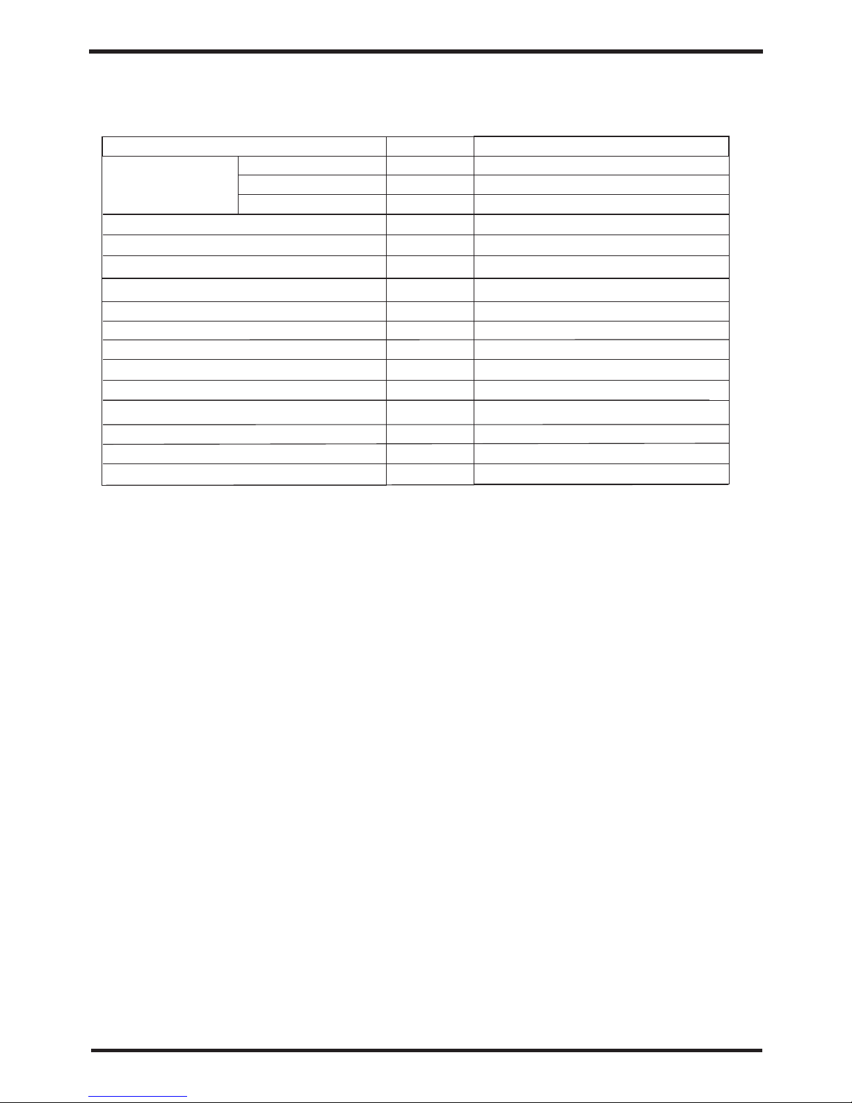
5
3.Specification
o o
Testing condition: ambient temperature DB/WB 20 C/15 C;
o o
outlet water 65 C, inlet water (return) 55 C;
117.0
37.5
70.0
AL LH T11 70R13 4
kW
kW
A
Heati ng Output
Power I nput
Runni ng Current
Unit Mo del
Recyc led-heatin g
2
2000×2
920
75
380V/ 3N~/50Hz
(Subj ect to data on the p ackage)
Namep late
W
RPM
dB(A)
mm
mm
kg
kg
Power S upply
Scrol l
Compr essor Typ e
4
Compr essor Quanti ty
Fan Qua ntity
Fan pow er input
Fan spe ed
Noise
Water pipe connection
Unit di mension (L/W /H)
Packa ge size(L/W/ H)
Net Weight
Gross w eight
DN80
Refri gerant Type
R134a
Packa ge
(Subject to drawings o f the h eat p ump )
3.1Performance Parameter List
6
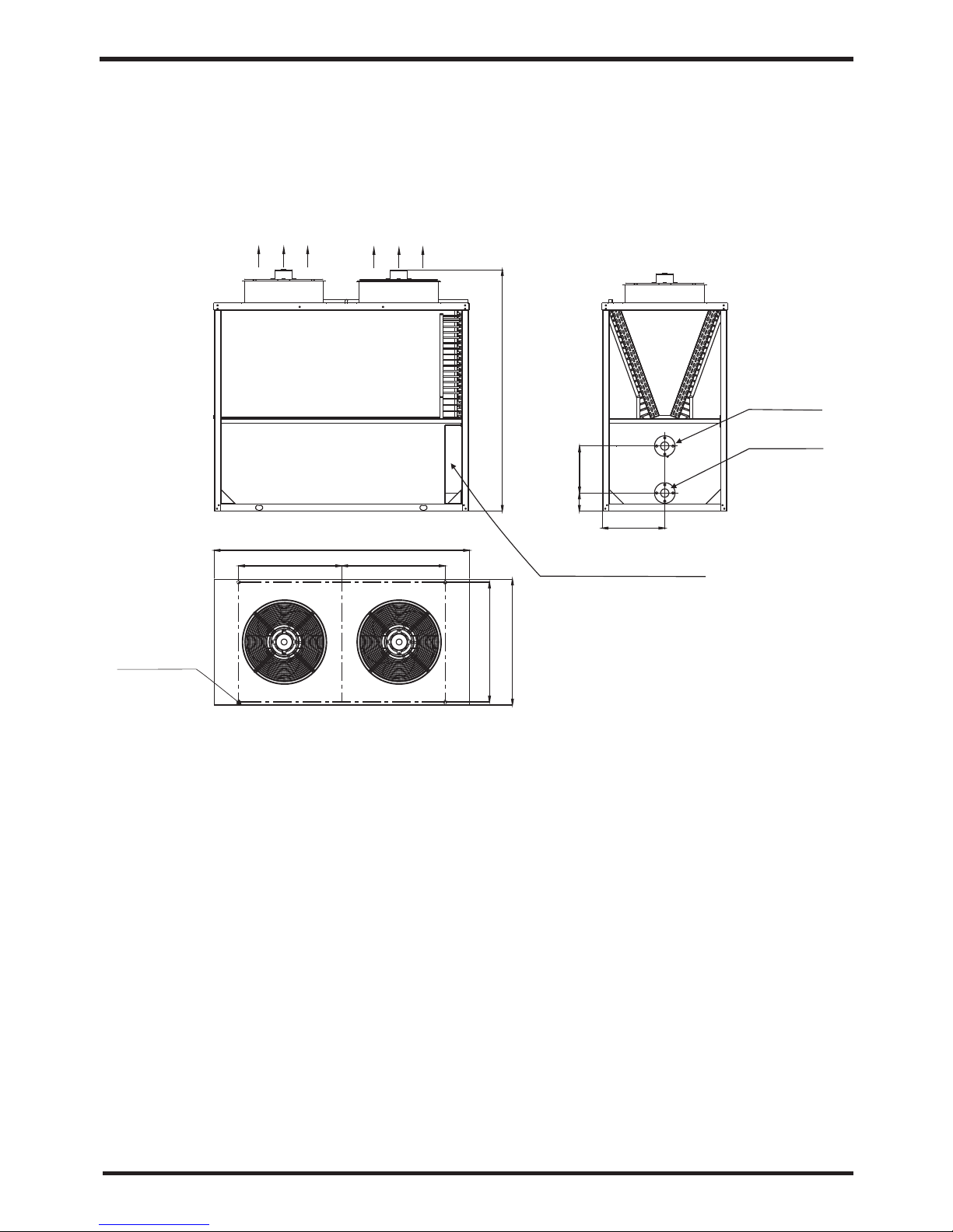
3.2
Outline Dimensional Drawing
3.Specification
Air-out di rec tio n
Installa tio n
Bottom Outlet
Water outlet
DN80 flang e
Electrical co ntr ol box
4-Φ16
2030
2180
900 900
1080
1020
400
175
530
Water inlet
DN80 flang e
Models: AL LHT 1170R13 4
4.Unit Function Description
The unit absorb energy from outside and release the heat according to the heat
exchanger, if the environment temperature is low, the heating capacity will be
attenuation.
Heating capacity
3 minutes protection
When the unit stop, if you restart the unit or turn on the manual switch, the unit will not run
in 3 minutes, it's the protection for the compressor.
If the environment temperature is too high, the unit will stop running to protect the
compressor.
Defrosting
Under the heating mode, the unit will defrost automatic to make sure the heating
efficiency (it will last 2-10 minutes).
Working condition
In order to use the unit correctly, please run the unit at environment temperature -7℃-43.
The unit includes sophisticated electronic devices, prohibited to use water from lake,
untreated river water and groundwater!
Power off
If the power supply is off, the unit will stop running. If the running unit is disturbed by
lightning, car radio, power grid fluctuations please cut off the manual power switch , and
then power on, press the on / off button.
leakage current protection
There is a leakage current action protection comes with the power supply wire.
Electric heating protection
When the water temperature reach 94℃, electric heating fuse will melt off (can not be
restored).
Hight pressure protection

7
4.Unit Function Description
The unit absorb energy from outside and release the heat according to the heat
exchanger, if the environment temperature is low, the heating capacity will be
attenuation.
Heating capacity
3 minutes protection
When the unit stop, if you restart the unit or turn on the manual switch, the unit will not run
in 3 minutes, it's the protection for the compressor.
If the environment temperature is too high, the unit will stop running to protect the
compressor.
Defrosting
Under the heating mode, the unit will defrost automatic to make sure the heating
efficiency (it will last 2-10 minutes).
Working condition
In order to use the unit correctly, please run the unit at environment temperature -7℃-43.
The unit includes sophisticated electronic devices, prohibited to use water from lake,
untreated river water and groundwater!
Power off
If the power supply is off, the unit will stop running. If the running unit is disturbed by
lightning, car radio, power grid fluctuations please cut off the manual power switch , and
then power on, press the on / off button.
leakage current protection
There is a leakage current action protection comes with the power supply wire.
Electric heating protection
When the water temperature reach 94℃, electric heating fuse will melt off (can not be
restored).
Hight pressure protection
8
5.Installation
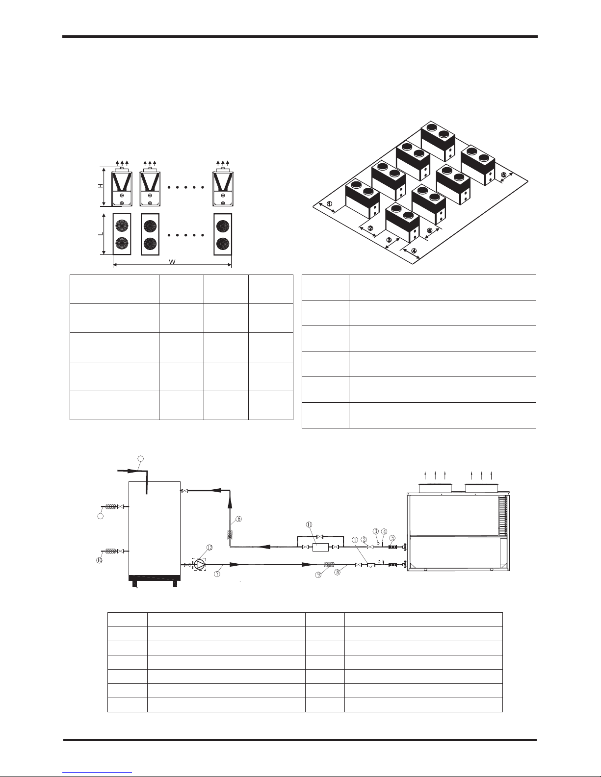
5.2 Installation Schematic Diagram
1
3
5
7
Y-type filter
Thermometer (0-100℃)
Connecting hose
Hot Water Circulating Pipe
2
4
6
8
Shut-off valve
Pressure gauge (0-1.0MPa)
Hot Water Circulating Pipe
Water supply pipes
Water Tank
Air-out di r
e
cti
on
1
3
8
Thermal insulation
Hot Water Supply Pipe
Electric auxiliary heater
Water pump
Hot Water Return Pipe
9
10
11
12
13
5.1Installation Space
2180
2180
2180
2180
3160
5240
7320
9400
2030
2030
2030
2030
Dimensions
Outline Dimensional
Drawing - Parallel Units
Schematic Diagram of Unit
Installation Position
Air-out direction
Parallel Mode
Double-
connected unit
Tripartite-
connected
Quadruple-
connected
Quintuplicate-
connected unit
L(mm)
L(mm) L(mm)
1
2
3
4
5
6
Maintenance space above 1800mm
Unit spacing above 1500mm
Maintenance space above 1500mm
Maintenance space above 1500mm
Maintenance space above 1800mm
Maintenance space above 1000mm
5.Installation
5.3 Model Selection
(1)Make comprehensive consideration of the required refrigerating (heating) capacity per unit
area according to climatic conditions, building use and heat preservation;
(2)Calculate the total load according to the unit load and the total area;
(3)Select the appropriate unit based on the total load and the application scope of the unit.
(4)Application occasions:
5.4Selection of the Installation Position

9
5.Installation
5.3 Model Selection
(1)Make comprehensive consideration of the required refrigerating (heating) capacity per unit
area according to climatic conditions, building use and heat preservation;
(2)Calculate the total load according to the unit load and the total area;
(3)Select the appropriate unit based on the total load and the application scope of the unit.
(4)Application occasions:
5.4Selection of the Installation Position
The unit can be installed on balconies, roofs, floors, or any other places easy to install
and reliable for load-bearing;
Air circulated places;
Places without thermal radiation or other heat sources;
Install a snow shed in winter;
Places without obstruction near the suction inlet or the exhaust outlet;
Places where the exhaust outlet is free from heavy winds;
Drainage channels shall be equipped around the machine to drain the condensed
water;
Enough space should be remained around the machine.
 Loading...