

Page 1
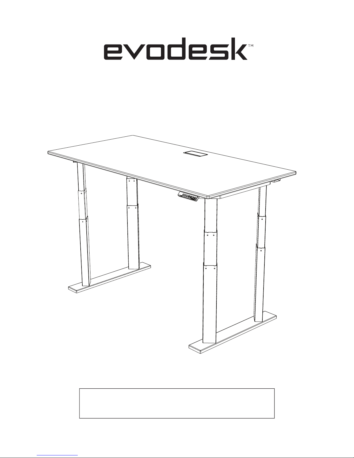
POWER ADJUSTABLE DESK
ASSEMBLY & OPERATION MANUAL
ED51115-SM90.014.01.0280v.A
Page 2

Caution, Use & Liability.................................................................................. Page 1
Parts & Components....................................................................................... Page 2
Components Diagram ................................................................................... Page 3
Assembly Instructions .................................................................................. Page 4
Troubleshooting .......................................................................................... Page 15
Technical Specifications............................................................................... Page 15
Warranty........................................................................................................... Page 16
TABLE OF CONTENTS
PREFACE
Thank you for choosing Evodesk!
We appreciate the trust and confidence you have placed in our
company. We are committed to providing you the best possible
value in power adjustable desks. We are sure that your Evodesk
will provide you many years of enjoyment and health.
-Evodesk Team
Preface, Table of Contents
Page 3
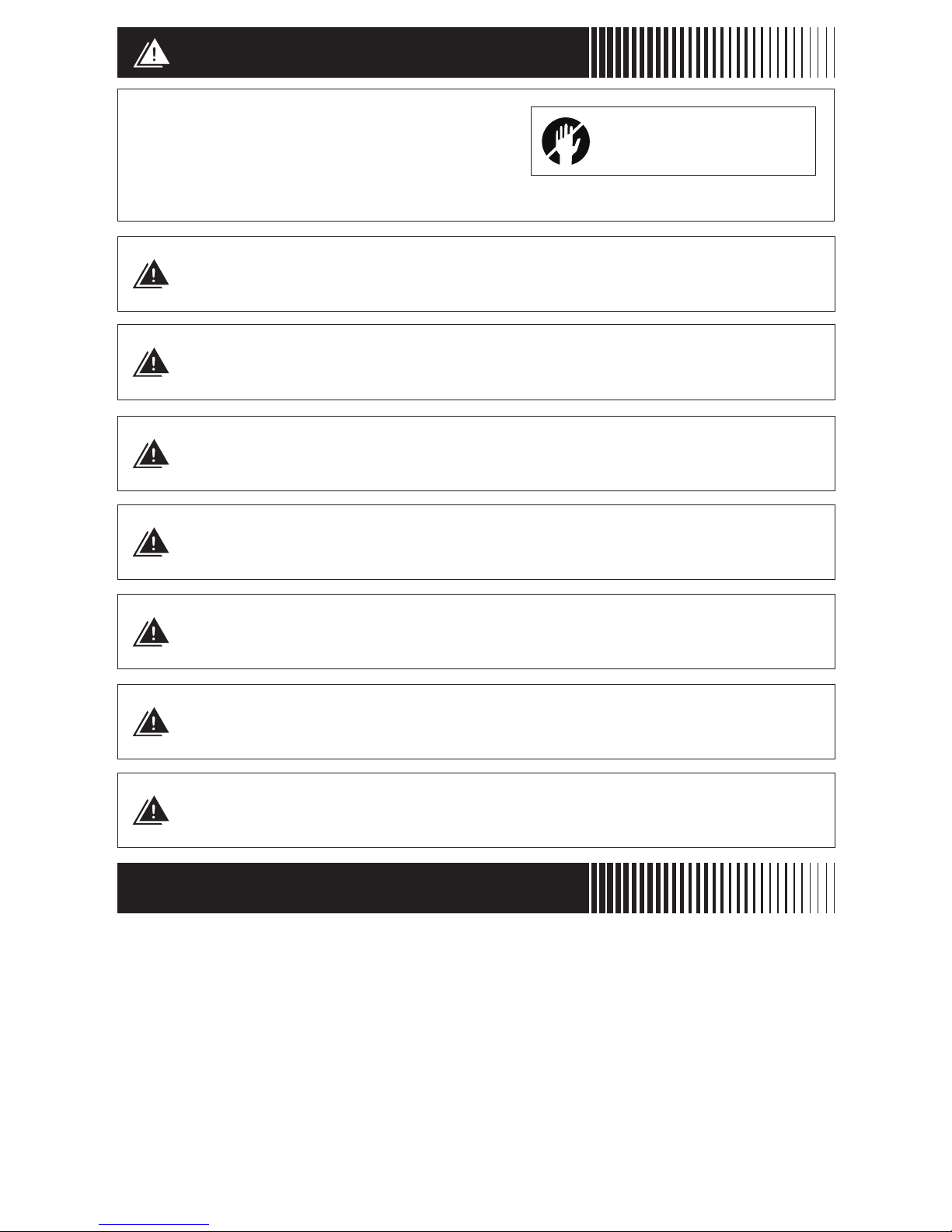
CAUTION
Make sure no obstacles are in the desk’s
path. Make sure the desktop is not
touching any walls. Make sure all cords
are appropriate length to accommodate
the change in height.
WARNING! PINCH POINT
Keep hands and fingers clear
Keep children away from electric height-adjustable desks, control
units and handsets. There is a risk of injury and electric shock.
Keep all electrical components away from liquids.
Do not sit or stand on the desk frame.
Do not crawl or lie under the desk frame.
Do not place any objects taller than 20” underneath the desk.
Do not open any of the components - the Legs, Control Box, or
Controller. There is a risk of electric shock.
The product is designed with a duty cycle of 10%
(2 min. on, 18 min. off).
In the event of a power outage or if the power cord is unplugged,
a manual reset may be necessary - see step 21.
USE & LIABILITY
This height adjustable desk has electric motors and is designed for use in dry
work areas only. The desk height is adjustable so that it can be positioned at
the most ergonomically suitable height. Any other use is at user’s risk. Under
no circumstances does the manufacturer accept warranty claims or liability
claims for damages caused from improper use or handling of the desk frame.
IMPORTANT:
Please read this manual carefully.
If this desk is sold, please provide this manual to the buyer.
Caution, Use & Liability - 1
Page 4
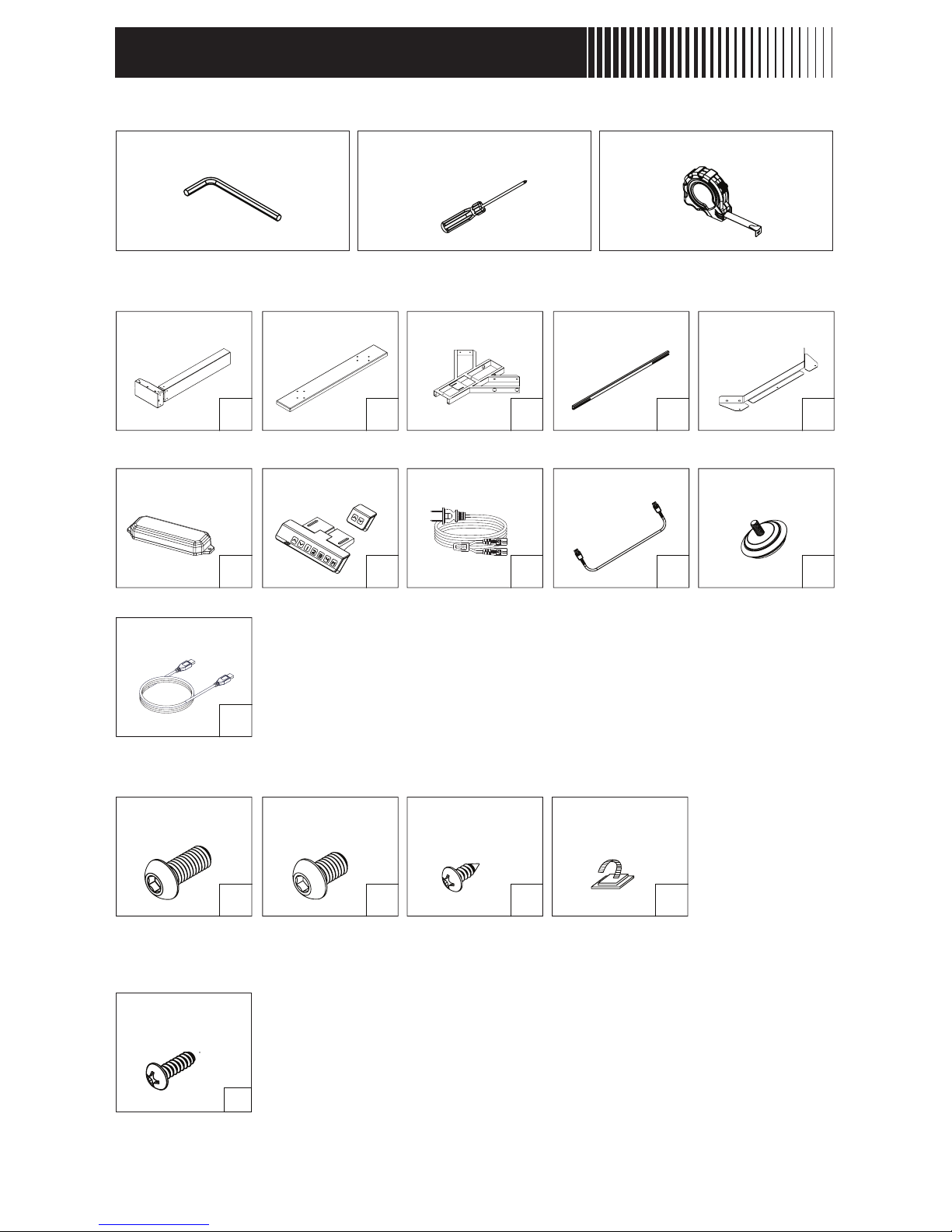
PARTS & COMPONENTS
TOOLS REQUIRED
COMPONENTS INCLUDED
Parts & Components - 2
4mm Allen Wrench (included) Phillips Head Screwdriver Tape Measure
HARDWARE INCLUDED
HARDWARE INCLUDED WITH DESKTOP
x4 x2 x2 x2 x2
x2 x1 x1 x2 x4
Columns Feet Upper Frame Center Rails Upper Brackets
Control Box Controller(s) Power Cord Lift Cables
(51”)
Leveling Studs
x16 x32 x2 x15
Machine Screws
M6x14
Machine Screws
M6x10
Wood Screws
ST M5x16
Cable Clips
x1
Link Cable
Phillips Screws
10-24 x ½”
x8
Page 5
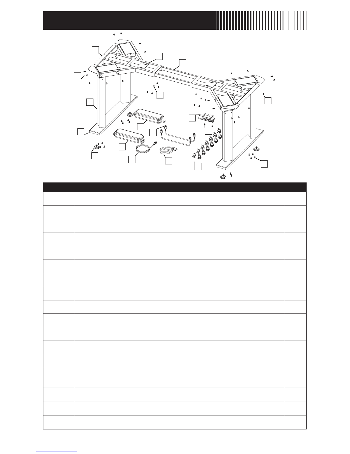
COMPONENTS DIAGRAM
Components Diagram - 3
1
2
3
4
5
6
7
8
9
10
11
12
13
14
15
16
17
Columns
Feet
Upper Frame
Center Rails
Upper Brackets
Control Box A
Control Box B
Controller
Power Cord
Lift Cables
Leveling Studs (pre-installed)
Machine Screws: M6x14
Machine Screws: M6x10
Phillips Screws:10-24 x ½”
Wood Screws: ST M5x16
Cable Clips
Link Cable
2
2
2
2
2
1
1
1
1
2
4
16
32
8
2
10
1
No. Description Qty
(Shipped separately in box with Evodesk desktop if purchased)
1
2
5
4
3
6
9
11
16
8
10
15
13
14
13
12
7
17
A
B
Page 6
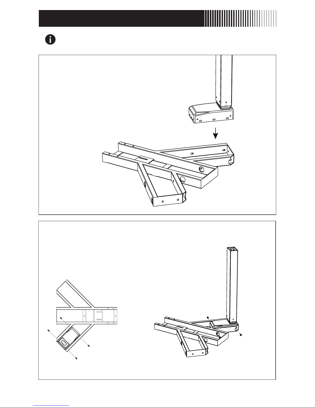
ASSEMBLY INSTRUCTIONS
BEFORE YOU BEGIN Lay out all components and hardware to
ensure that you have all the parts listed on the parts page.
STEP 1
Lay the frame with the Rubber Pads facing down.
Insert a column into one of the openings as shown.
Assembly Instructions - 4
STEP 2
Use four of the M6-10mm screws to secure the
Columns to the Upper Frame. Do not fully
tighten the screws at this time. Column should
have some “wiggle room”.
Page 7
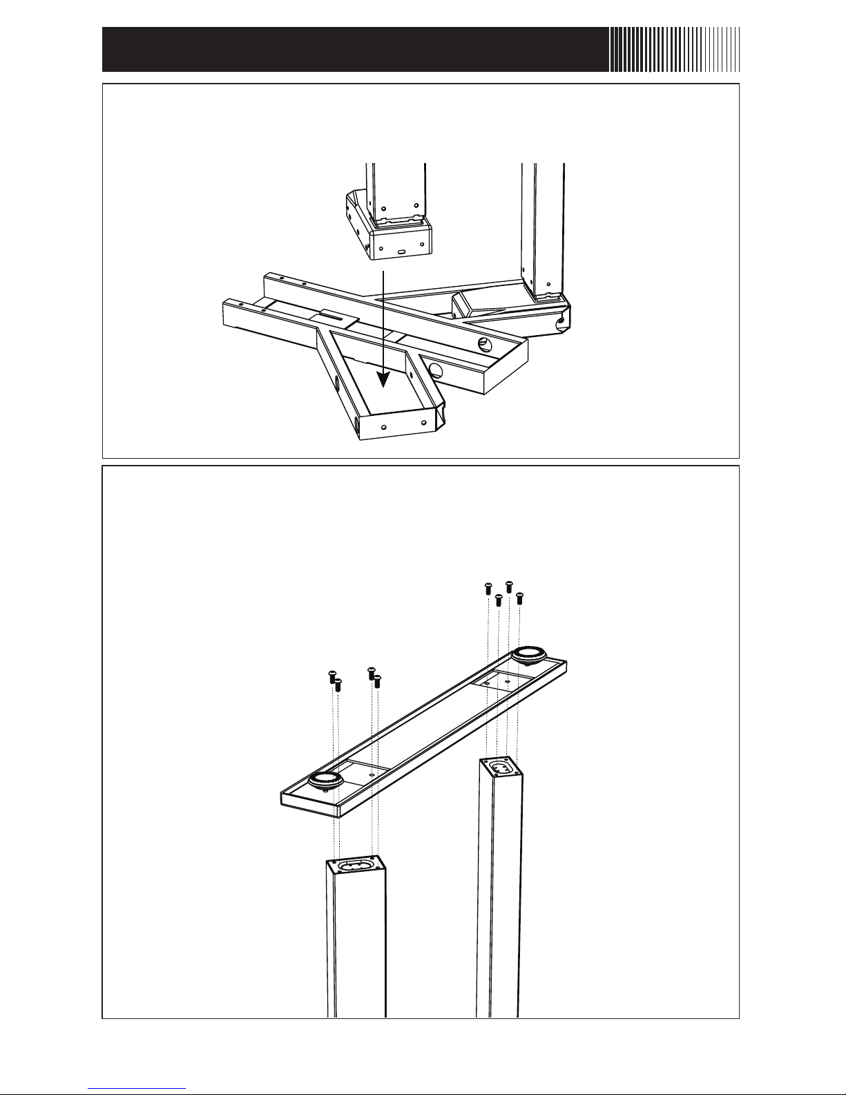
ASSEMBLY INSTRUCTIONS cont.
STEP 4
Attach one of the feet to the ends of the Columns
using eight of the M6-14mm screws.
STEP 3
Repeat for the other opening on the Upper Frame.
Assembly Instructions cont. - 5
Page 8
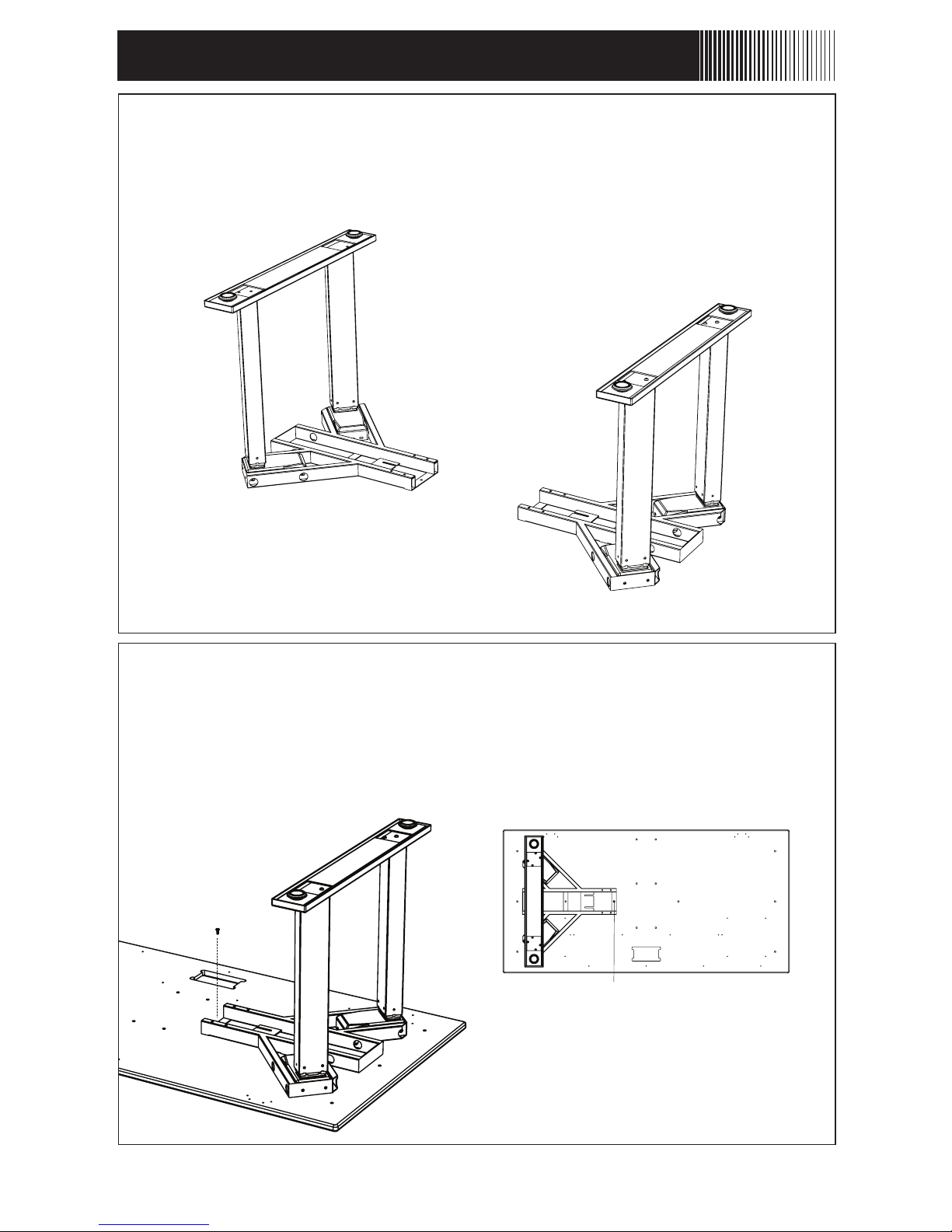
ASSEMBLY INSTRUCTIONS cont.
Assembly Instructions cont. - 6
STEP 6
Align the hole furthest from the columns with the steel insert
on the desktop. Attach with one of the 10-24 screws included
with the desktop. Do not tighten these yet. Screw should only
be in 75% of the way in at this time.
*Align with desk insert
STEP 5
Repeat Steps 1 through 6 to complete the
second column group.
Page 9
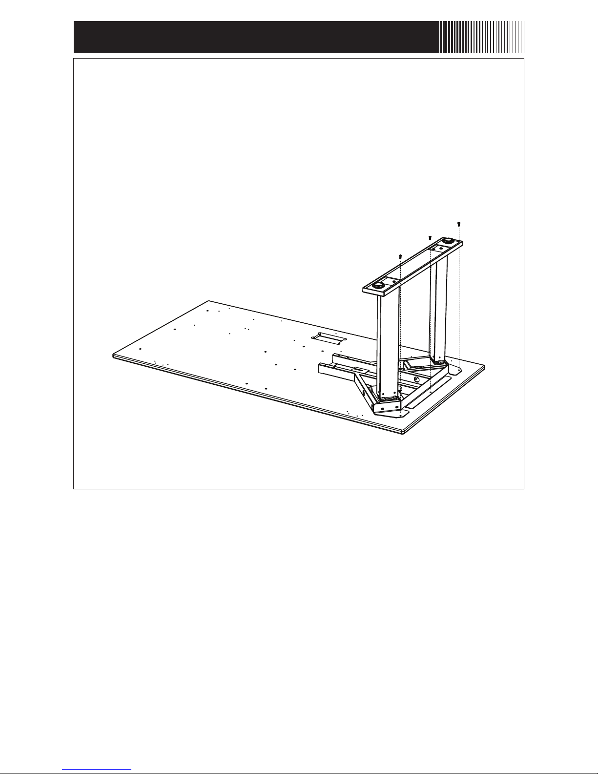
ASSEMBLY INSTRUCTIONS cont.
Assembly Instructions cont. - 7
STEP 7
Align the Upper Bracket with the Upper Frame as shown. Use
three 10-24 screws included with the desktop. These should
also only be screwed in 75% of the way.
Page 10
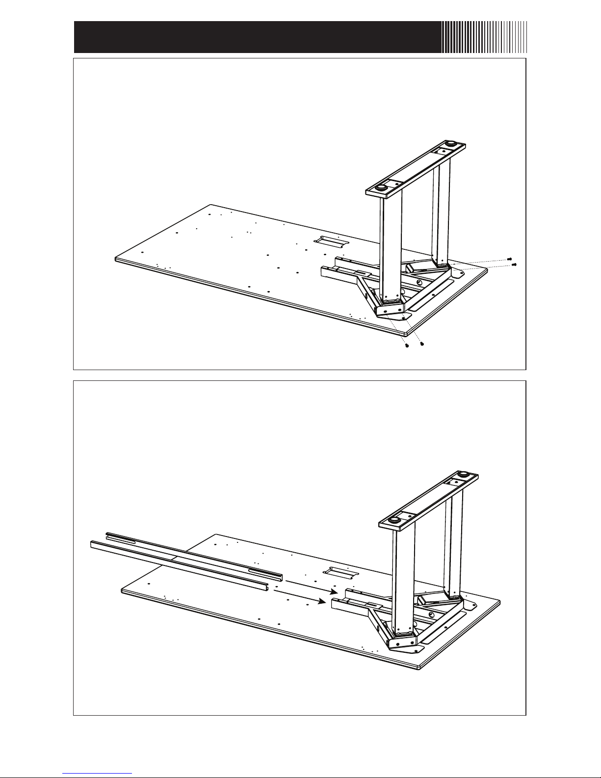
ASSEMBLY INSTRUCTIONS cont.
Assembly Instructions cont. - 8
STEP 8
Secure the Upper Bracket to the Upper Frame using four of the
M6-10 screws. Firmly tighten after all four have been started.
STEP 9
Slide in both Center Rails into the openings of the
Upper Frame as shown.
Page 11
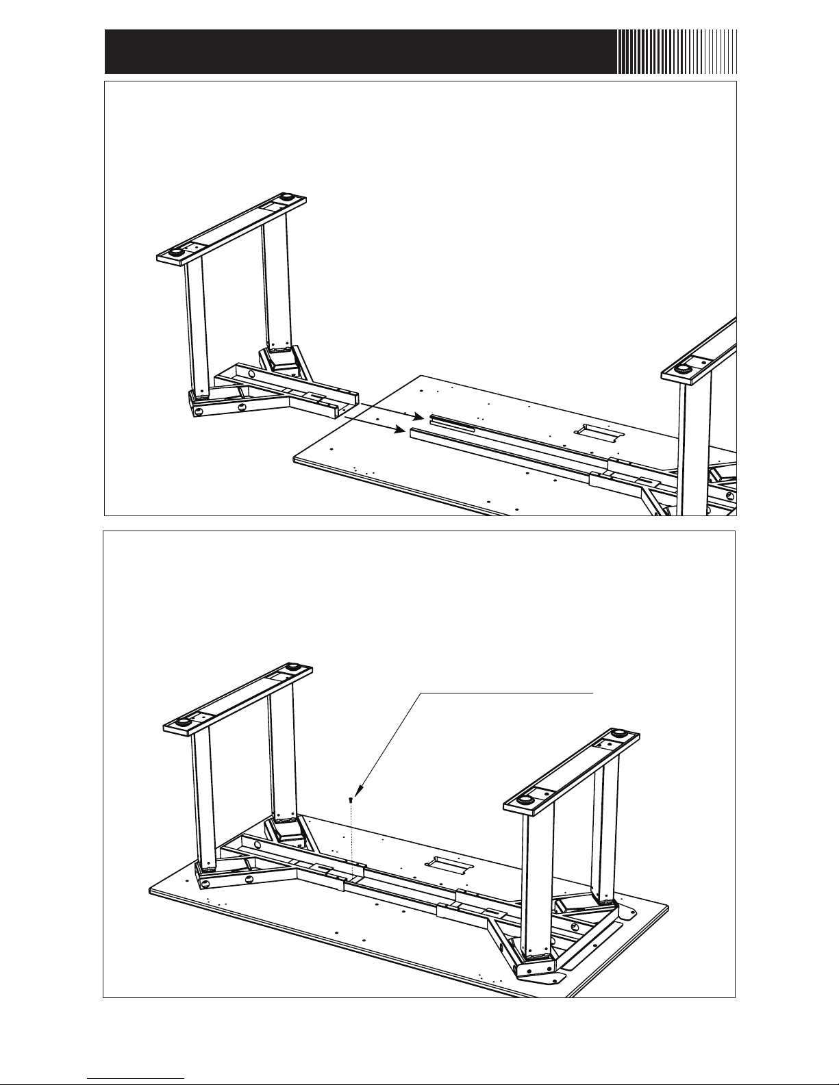
STEP 11
Adjust the second column group position to align the outermost
frame hole with matching insert on the desktop. Attach with one
of the 10-24 screws again being only about 75% inserted.
STEP 10
Slide the second column group over the exposed ends of
the Center Rails.
ASSEMBLY INSTRUCTIONS cont.
Assembly Instructions cont. - 9
10-24 Button Head Screw
Page 12
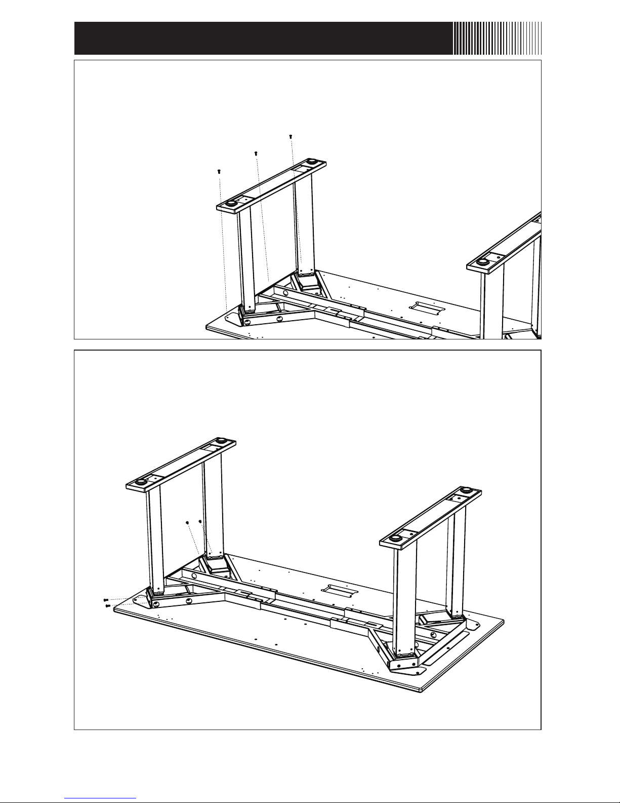
STEP 12
Align the second Upper Bracket with the second Upper
Frame as shown. Use the remaining three 10-24 screws
included with the desktop.
ASSEMBLY INSTRUCTIONS cont.
Assembly Instructions cont. - 10
STEP 13
Secure the Upper Bracket to the Upper Frame using four of the
M6-10 screws. Firmly tighten after all four have been started.
Page 13
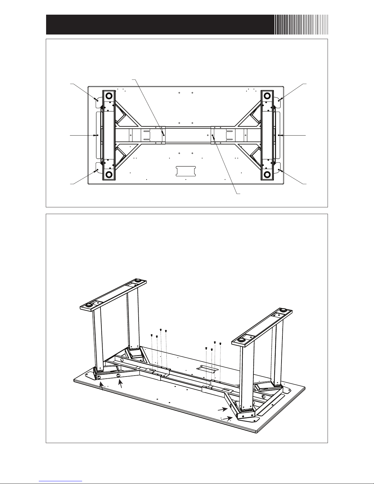
STEP 14
Now all the 10-24 screws can be firmed tightened.
ASSEMBLY INSTRUCTIONS cont.
Assembly Instructions cont. - 11
STEP 15
Use the eight M6-10mm screws in the locations shown to lock
the Center Rails. These screws should be firmly tightened. Tightening can also be applied to the looser screws from Step 2.
(3 screws from each column should be accessible.)
4
5
1
2
3
6
7
8
Page 14
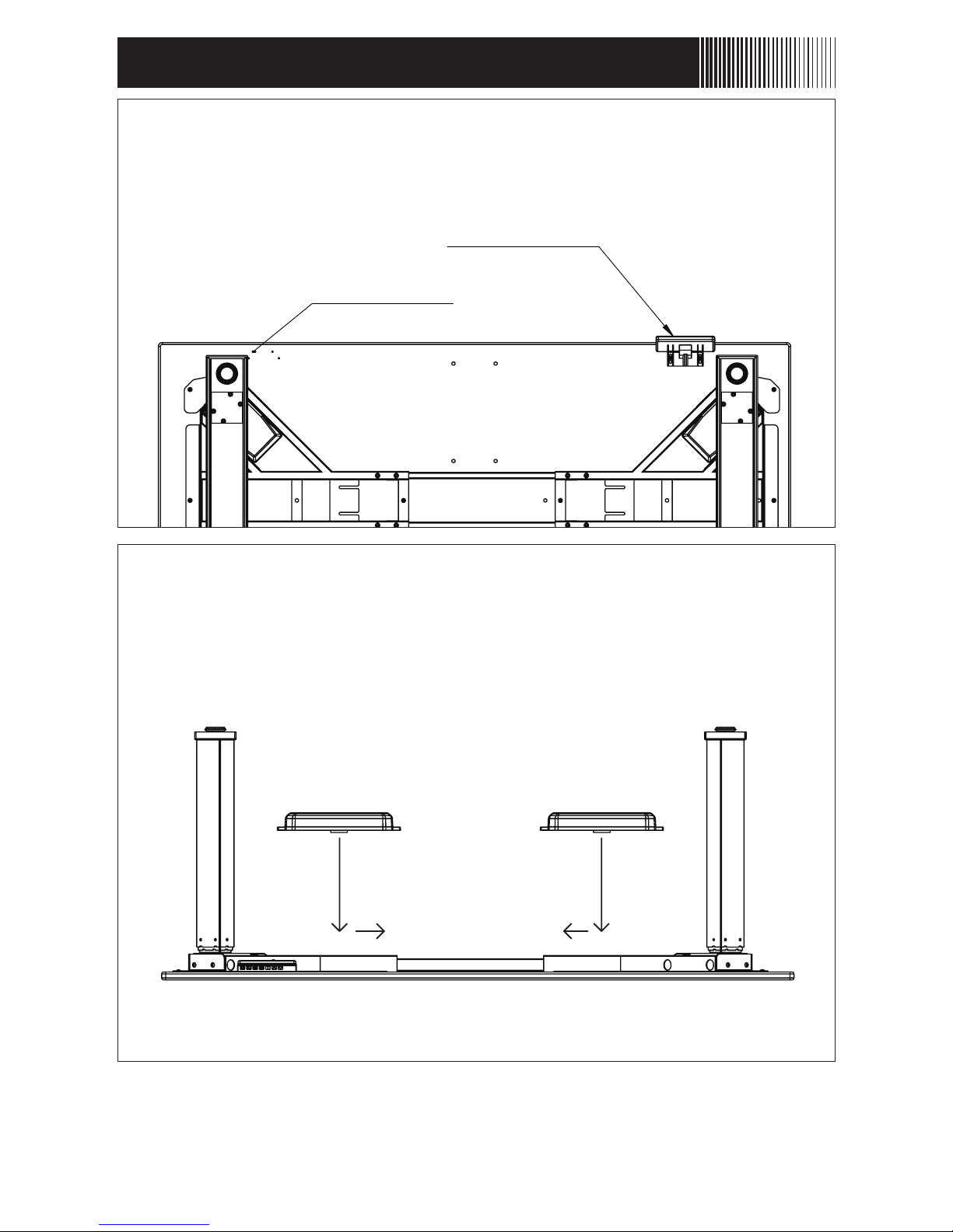
STEP 16
Use the two wood screws to attach the Control Panel in either
the right or left hand position. Do not over-tighten these
screws, only firm enough to prevent the panel from moving.
ASSEMBLY INSTRUCTIONS cont.
Assembly Instructions cont. - 12
STEP 17
The Control Box attached by placing it between the frame and sliding
it over the open slots on the frame's control box mount. Do this for
both boxes on either side.
NOTE
Control Box A should be placed on the same side as the handset.
Left Hand Position
Right Hand Position
A B
Page 15
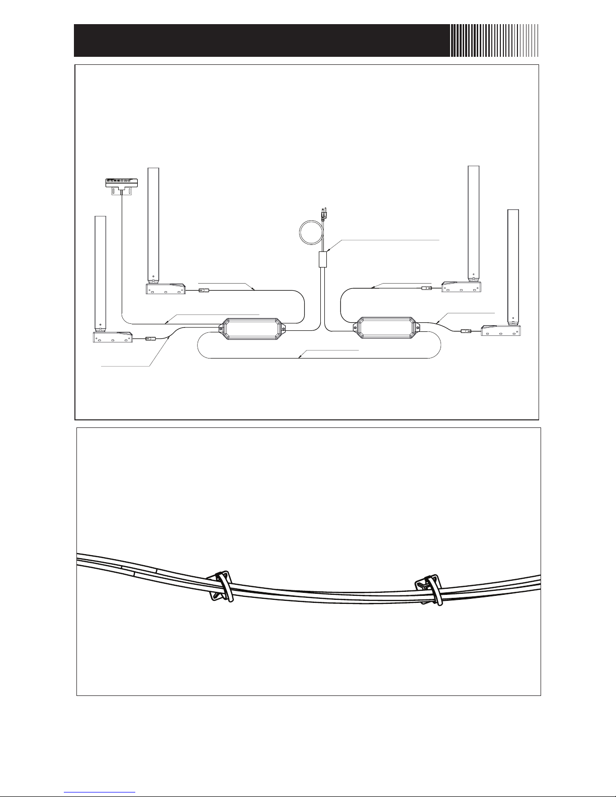
STEP 19
Use the adhesive-backed clips to secure loose cables and keep
the underside organized and prevent hanging cables.
Note: Only two lift cables are needed. Two of the column cables should
reach the control boxes without extra cables.
ASSEMBLY INSTRUCTIONS cont.
Assembly Instructions cont. - 13
STEP 18
Connect the Columns to the Control Box nearest to them. Use the
Link cable to connect to connect the two Control Boxes. The Power
Cable should have two connectors that should each connect to a
Control Box. The Controller must be connected to box “A”.
Link Cable
A B
Direct
Connect
Lift Cable
Lift Cable
Direct
Connect
Y-Split Power Cable
Controller Cable
Page 16
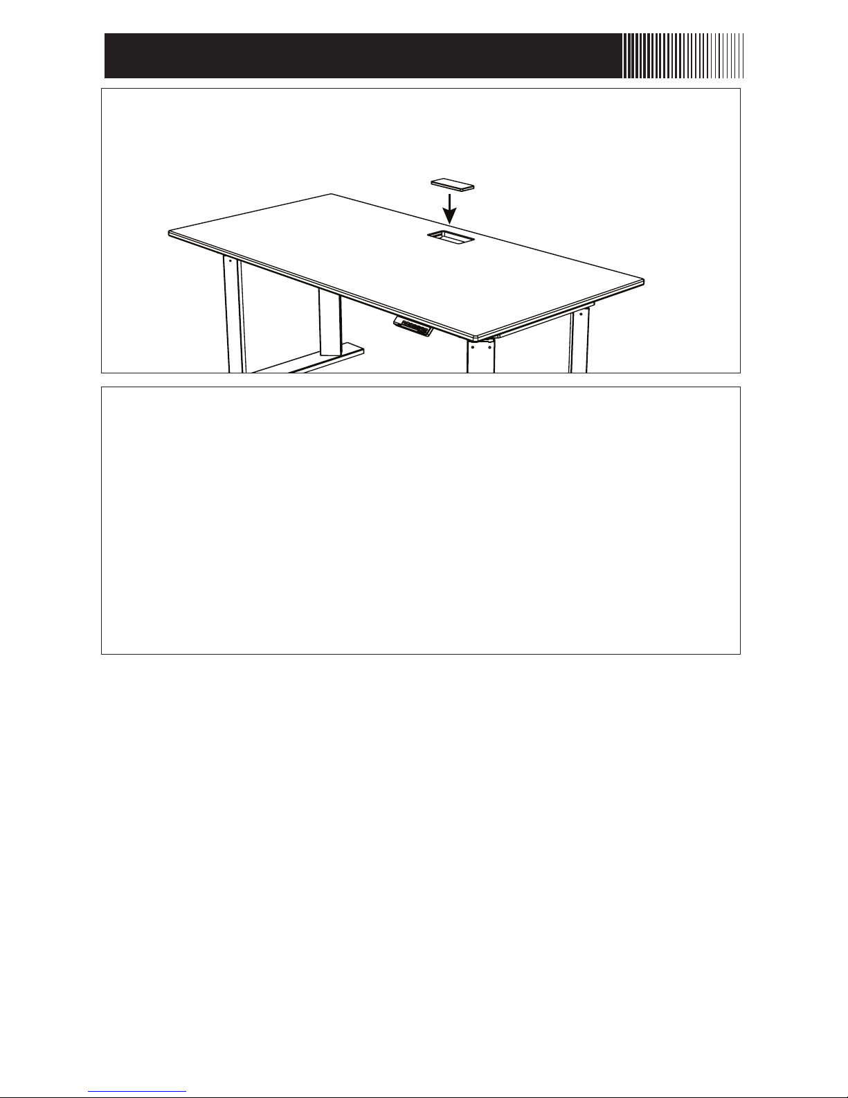
STEP 20
With two people, firmly grab the desk and slowly turn it right-side-up.
STEP 21
Plug the Power Cord into a 110v outlet.
Reset Procedure: Press and hold DOWN button on Controller (#7)
until desk reaches its lowest height. Release DOWN button. Press
and hold DOWN button again until LED displays “RST” or about 10
seconds on non-LED models. Release DOWN button. Press and hold
DOWN buttonagain until desk slightly lowers, rises and stops.
Release DOWN button.
Your desk is now ready to use.
ASSEMBLY INSTRUCTIONS cont.
Assembly Instructions cont. - 14
Page 17

TROUBLESHOOTING
Technical Specifications - 15
TECHNICAL SPECIFICATIONS
Height Range
Base Width
Travel Speed
Weight Capacity
Duty Cycle
23.5” - 49” (excluding desktop)
42.25” min. - 74” max
1.5” per second (no load)
560 lbs.
10%. Max. 2 mins on, 18 mins off
Soft start / stop
Adjustable Leveling Studs
4 Memory presets
If your desk is not functioning properly it may need to be reset. Unplug the
power cord for 20 seconds. Plug the power cord back in and follow the RESET
procedure outlined in Step 21.
If your desk has a handset with an LED readout and it displays an error code
“E01 - E13”, confirm that all wired connections are secure (legs to cables, cables
to control box). Then perform the reset procedure outlined in Step 21.
If the error message persists after the reset procedure, contact EvoDesk. If the
height difference between the legs exceeds 1.5 inches, stop the reset procedure
and contact EvoDesk immediately.
If the handset displays “Hot”, allow EvoDesk to cool down for 20 minutes.
Page 18

Warranty - 16
PLEASE READ THIS DOCUMENT CAREFULLY. IT CONTAINS VERY IMPORTANT INFORMATION ABOUT YOUR RIGHTS AND OBLIGATIONS, AS WELL AS LIMITATIONS AND EXCLUSIONS THAT MAY APPLY. YOU MUST PRESENT PROOF OF PURCHASE (RECEIPT) TO
OBTAIN WARRANTY SERVICE.
This Statement of Warranty Terms and Conditions sets forth the warranties provided by
Evodesk (“Manufacturer”) to its customers with respect to the Products purchased. By
accepting delivery of the Products, you agree to be bound by and accept these terms and
conditions.
The Evodesk Product is warranted by Manufacturer to be free from defects in material and
workmanship for five (5) years from the date of purchase.
The Warranty covers parts and labor costs to repair your Product in the event your product
fails to properly operate due to defects in materials or workmanship of the frame, electric
motors, control box, push-button controller, or desktop. If we determine, at our sole discretion, that your Product cannot be repaired, we will replace it with a Product of like kind and
quality that is of comparable performance. Replacement parts or products may be new or
rebuilt to meet the specifications of the original product at our discretion. Parts replaced
under the terms and conditions of this Warranty and Extended Warranty become the sole
property of Manufacturer except where prohibited by law. Our obligations under this
Warranty and Extended Warranty will be fulfilled in their entirety if we replace your Product
with a new or refurbished Product pursuant to these terms and conditions.
In order to obtain performance of the warranty obligations, the original purchaser must
return the Product together with proof of purchase date (receipt) either in person or ship
Product to Manufacturer. Customer shall prepay transportation charges to and from Manufacturer facility.
Phone/Web Support
To receive phone assistance, call 1-888-615-5721
Phone assistance for your covered Product includes: Answers to questions regarding
Product use, diagnosis of issues and recommendation of repair options, explanation of
Warranty or Extended Warranty, coverage and claims.
To receive online assistance visit: www.evodesk.com.
Exclusions to Coverage
The Warranty and Extended Warranty does not cover:
Damage to your Product caused by accident, abuse, neglect, intentional physical damage,
misuse (including faulty installation, repair, or maintenance by anyone other than the Manufacturer’s authorized service provider), unauthorized modification, extreme environment
(including extreme temperature or humidity), external condensation, mold, immersion/submersion in liquid (e.g. pool, bathtub, etc.), lightning, fire, flood, insect infestation, rodents,
war, terrorism, computer software related failures, Acts of God or other external causes.
WARRANTY
Page 19

Exclusions to Coverage (cont.)
Normal wear and tear of the desktop or painted finish
Cosmetic damage to your product including but not limited to scratches, dents and broken
plastic on parts that does not otherwise affect its functionality or materially impair your use.
Products with a serial number that have been altered, defaced, or removed.
Fees or costs related to third-party contracts, consequential or incidental damages, including but not limited to loss of use, loss of business, loss of profits, loss of data, downtime,
charges for time and effort, or “no problem found” diagnoses.
This Warranty or Extended Warranty only covers the electric desk, and shall not include
items attached to the covered electric desk, such as components or add-on accessories,
even if purchased with the electric desk. Accessories not covered include, but are not
limited to, keyboard platforms, cable management trays, speakers, monitor arms, treadmills,
casters and CPU mounts.
Disclaimer
EXCEPT AS EXPRESSLY SET FORTH ABOVE, EVODESK MAKES NO REPRESENTATION OR
WARRANTY OF ANY KIND, EXPRESS, IMPLIED OR STATUTORY, INCLUDING BUT NOT
LIMITED TO WARRANTIES OF MERCHANTABILITY, FITNESS FOR A PARTICULAR
PURPOSE, TITLE OR NONINFRINGEMENT, OR WARRANTIES OR OBLIGATIONS ARISING
FROM A COURSE OF DEALING, USAGE OR TRADE PRACTICE.
Limitation of Liability
IN NO EVENT WILL EVODESK OR ITS AFFILIATES OR SUPPLIERS BE LIABLE FOR ANY
LOSS OF USE, INTERRUPTION OF BUSINESS, LOST PROFITS, OR LOST DATA, OR
INDIRECT, SPECIAL, INCIDENTAL OR CONSEQUENTIAL DAMAGES OF ANY KIND
REGARDLESS OF THE FORM OF ACTION, WHETHER IN CONTRACT, TORT (INCLUDING
NEGLIGENCE), STRICT LIABILITY OR OTHERWISE, EVEN IF EVODESK OR ITS AFFILIATE
OR SUPPLIER HAS BEEN ADVISED OF THE POSSIBILITY OF SUCH DAMAGE, AND
WHETHER OR NOT ANY REMEDY PROVIDED SHOULD FAIL OF ITS ESSENTIAL PURPOSE.
THE TOTAL CUMULATIVE LIABILITY TO CUSTOMER, FROM ALL CAUSES OF ACTION AND
ALL THEORIES OF LIABILITY, WILL BE LIMITED TO AND WILL NOT EXCEED THE
PURCHASE PRICE OF THE PRODUCT PAID BY CUSTOMER.
Without limiting the generality of the preceding sentence, Evodesk shall not be liable for
personal injury or property damage.
Assignment of Rights
The warranties contained herein extend only to the original purchaser of the Products and
no attempt to extend the warranties to any subsequent transferee of the Products shall be
valid or enforceable without the express written consent of Evodesk.
Governing Law
Interpretation and enforcement of these terms and conditions shall be governed by the
laws of the State of Texas.
WARRANTY (cont.)
Warranty - 17
Page 20

Your lifestyle and career evolves. We made Evodesk to evolve with you. This
means Evodesk may be the last desk you’ll ever need to buy. The Evolution
frame system moves between 48”, 60” and 72” or larger without having to buy a
new desk. Simply expand the frame and swap tops. You can also add any option
not chosen with your original purchase, including our most popular accessories,
the Evodesk Keyboard Platform, Programmable Controller, Casters and more.
See all the ways you can upgrade your Evodesk to create the perfect standing
desk workstation at Evodesk.com/store/upgrade
UPGRADING YOUR EVODESK
Join the Evodesk community on your favorite social networks Facebook and
Twitter to share your custom Evodesk and stay up-to-date on the latest Evodesk
products and promotions!
EVODESK SOCIAL
Welcome to the Evodesk family! Reviews from the Evodesk community are
extremely valuable to others when they are searching for a new desk. Please
share your thoughts with others by submitting a written or video review. Thank
you for taking a moment to tell us about your experience.
Evodesk.com/submit/review
WE VALUE YOUR FEEDBACK
facebook.com/evodesk
twitter.com/evodesk
Warranty - 18
Page 21

NOTES
Page 22

NOTES
Page 23

Page 24

2251 Picadilly Drive
Suite. C-341
Austin, TX 78660
(888) 615-5721
evodesk.com
For technical support visit evodesk.com/support
 Loading...